US7322535B2 - Faucet spray head - Google Patents
Faucet spray head Download PDFInfo
- Publication number
- US7322535B2 US7322535B2 US11/041,785 US4178505A US7322535B2 US 7322535 B2 US7322535 B2 US 7322535B2 US 4178505 A US4178505 A US 4178505A US 7322535 B2 US7322535 B2 US 7322535B2
- Authority
- US
- United States
- Prior art keywords
- spray head
- faucet
- spout
- spray
- unit
- Prior art date
- Legal status (The legal status is an assumption and is not a legal conclusion. Google has not performed a legal analysis and makes no representation as to the accuracy of the status listed.)
- Active, expires
Links
- 239000007921 spray Substances 0.000 title claims abstract description 170
- 238000005273 aeration Methods 0.000 claims abstract description 45
- XLYOFNOQVPJJNP-UHFFFAOYSA-N water Substances O XLYOFNOQVPJJNP-UHFFFAOYSA-N 0.000 claims description 27
- 239000012530 fluid Substances 0.000 claims description 16
- 238000006073 displacement reaction Methods 0.000 claims description 7
- 125000006850 spacer group Chemical group 0.000 claims description 3
- 238000000034 method Methods 0.000 claims description 2
- 239000011159 matrix material Substances 0.000 description 2
- 239000011148 porous material Substances 0.000 description 2
- RYGMFSIKBFXOCR-UHFFFAOYSA-N Copper Chemical compound [Cu] RYGMFSIKBFXOCR-UHFFFAOYSA-N 0.000 description 1
- 230000006978 adaptation Effects 0.000 description 1
- 238000010276 construction Methods 0.000 description 1
- 238000011109 contamination Methods 0.000 description 1
- 229910052802 copper Inorganic materials 0.000 description 1
- 239000010949 copper Substances 0.000 description 1
Images


Classifications
-
- B—PERFORMING OPERATIONS; TRANSPORTING
- B05—SPRAYING OR ATOMISING IN GENERAL; APPLYING FLUENT MATERIALS TO SURFACES, IN GENERAL
- B05B—SPRAYING APPARATUS; ATOMISING APPARATUS; NOZZLES
- B05B1/00—Nozzles, spray heads or other outlets, with or without auxiliary devices such as valves, heating means
- B05B1/14—Nozzles, spray heads or other outlets, with or without auxiliary devices such as valves, heating means with multiple outlet openings; with strainers in or outside the outlet opening
- B05B1/16—Nozzles, spray heads or other outlets, with or without auxiliary devices such as valves, heating means with multiple outlet openings; with strainers in or outside the outlet opening having selectively- effective outlets
- B05B1/1627—Nozzles, spray heads or other outlets, with or without auxiliary devices such as valves, heating means with multiple outlet openings; with strainers in or outside the outlet opening having selectively- effective outlets with a selecting mechanism comprising a gate valve, a sliding valve or a cock
- B05B1/1636—Nozzles, spray heads or other outlets, with or without auxiliary devices such as valves, heating means with multiple outlet openings; with strainers in or outside the outlet opening having selectively- effective outlets with a selecting mechanism comprising a gate valve, a sliding valve or a cock by relative rotative movement of the valve elements
- B05B1/1645—Nozzles, spray heads or other outlets, with or without auxiliary devices such as valves, heating means with multiple outlet openings; with strainers in or outside the outlet opening having selectively- effective outlets with a selecting mechanism comprising a gate valve, a sliding valve or a cock by relative rotative movement of the valve elements the outlets being rotated during selection
- B05B1/1654—Nozzles, spray heads or other outlets, with or without auxiliary devices such as valves, heating means with multiple outlet openings; with strainers in or outside the outlet opening having selectively- effective outlets with a selecting mechanism comprising a gate valve, a sliding valve or a cock by relative rotative movement of the valve elements the outlets being rotated during selection about an axis parallel to the liquid passage in the stationary valve element
-
- E—FIXED CONSTRUCTIONS
- E03—WATER SUPPLY; SEWERAGE
- E03C—DOMESTIC PLUMBING INSTALLATIONS FOR FRESH WATER OR WASTE WATER; SINKS
- E03C1/00—Domestic plumbing installations for fresh water or waste water; Sinks
- E03C1/02—Plumbing installations for fresh water
- E03C1/04—Water-basin installations specially adapted to wash-basins or baths
- E03C1/0404—Constructional or functional features of the spout
-
- E—FIXED CONSTRUCTIONS
- E03—WATER SUPPLY; SEWERAGE
- E03C—DOMESTIC PLUMBING INSTALLATIONS FOR FRESH WATER OR WASTE WATER; SINKS
- E03C2201/00—Details, devices or methods not otherwise provided for
- E03C2201/30—Diverter valves in faucets or taps
Definitions
- the present invention relates to a spray head, and, more particularly, to a spray head for a faucet, such as a kitchen faucet.
- a typical faucet such as a kitchen faucet, includes hot and cold water controllers, and a spout having one end coupled to the controls and another end connected to an aeration head.
- the aeration head may be formed using a mesh screen defining a matrix of very small pores thorough which the water passes, thereby separating the delivered water stream into a multitude of finely divided streams concentrated in a small area.
- a separate retractable spray hose with a spray nozzle is coupled to the controls as well.
- a spray nozzle typically includes a head having a ring of individual spray nozzles which are positioned and designed to provide a plurality of streams, lesser in number than the multitude of finely divided streams of the aeration head of the faucet, and with each stream having a larger flow volume than an individual stream from the aeration head.
- the present invention provides a faucet spray head having both an aeration unit and spray unit which are individually selectable, for example, via a rotation of a spray head mechanism of the faucet spray head.
- a selection between an aeration mode and a spray mode may be made, for example, with a relatively small rotational displacement of the spray head mechanism.
- the invention in one form thereof, is directed to a faucet spray head for attachment to a faucet spout.
- the faucet spray head includes a spout adapter configured for attachment to the faucet spout.
- the spout adaptor has a body defining an interior chamber.
- the interior chamber has at least one exit passage.
- a spray head mechanism is rotatably coupled to the body.
- the spray head mechanism includes an aeration unit and a spray unit that are individually selected based on a rotational position of the spray head mechanism in relation to the spout adaptor.
- the invention in another form thereof, is directed to a method for operating a faucet spray head attached to a faucet spout, including rotating an outer housing of the faucet spray head in a first rotational direction to select a spray unit for operating the faucet spray head in a spray mode; and rotating the outer housing of the faucet spray head in a second rotational direction opposite to the first rotational direction to select an aeration unit for operating the faucet spray head in an aeration mode.
- the invention in still another form thereof, is directed to a kit for a faucet spray head, including a switching plate having at least one perimeter opening defining a first fluid path and at least one interior opening defining a second fluid path, and a number of interior opening seals equal to or greater than the number of interior openings in the switching plate.
- An advantage of the present invention is that it provides a unitary faucet spray head for a faucet, such as a kitchen faucet, that can selectively operate in either of an aeration mode and a spray mode.
- Another advantage is that selection between the aeration mode and the spray mode is achieved by a simple rotational displacement of the spray head.
- selection between the aeration mode and the spray mode may be achieved by a rotational displacement of the spray head of about 90 degrees or less.
- FIG. 1 is a perspective view of a faucet including an embodiment of a faucet spray head in accordance with the present invention.
- FIG. 2 is a perspective exterior view of one embodiment of the faucet spray head of FIG. 1 .
- FIG. 3A is a top down exploded perspective view of the faucet spray head of FIG. 2 depicting an arrangement of components when the spray mode is selected.
- FIG. 3B is a bottom up exploded perspective view of the faucet spray head of FIG. 2 depicting an arrangement of components when the spray mode is selected.
- FIG. 3C is section view taken along line 3 C- 3 C of FIG. 2 showing a flow path to the spray unit.
- FIG. 4A is a top down exploded perspective view of the faucet spray head of FIG. 2 depicting an arrangement of components when the aeration mode is selected.
- FIG. 4B is a bottom up exploded perspective view of the faucet spray head of FIG. 2 depicting an arrangement of components when the aeration mode is selected.
- FIG. 4C is section view taken along line 3 C- 3 C of FIG. 2 showing a flow path to the aeration unit.
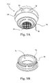
- FIGS. 5A and 5B show an alternative to the embodiment of a faucet spray head of FIG. 2 , wherein the housing portion is formed integral with the annular body of the spray unit to form an integral spray housing unit.
- FIG. 1 there is shown a perspective view of a faucet 10 including a faucet spray head 12 configured in accordance with the present invention.
- Faucet 10 may be mounted, for example, to a kitchen sink 14 as shown, or to other sink structures, such as for example, a utility sink.
- Faucet 10 further includes a base 16 , a faucet spout 18 , a hot water controller 20 and a cold water controller 22 .
- Hot and cold water conduits 24 , 26 respectively, such as for example copper pipes, connect faucet 10 to a water source (not shown).
- Faucet spout 18 is connected at a first end to base 16 and at a second end to faucet spray head 12 .
- Base 16 supplies a flow of water, including hot and/or cold water in proportions as selected by hot water controller 20 and a cold water controller 22 , to faucet spray head 12 .
- FIG. 2 is a perspective exterior view of one embodiment of faucet spray head 12 .
- faucet spray head 12 includes an outer housing 28 , a housing portion 30 , a spray unit 32 and an aeration unit 34 .
- Housing portion 30 is threadably connected to outer housing 28 , and retains spray unit 32 and aeration unit 34 in outer housing 28 .
- rotating outer housing 28 of faucet spray head 12 in a first rotational direction 36 selects spray unit 32 for operating faucet spray head 12 in a spray mode.
- Rotating outer housing 28 of faucet spray head 12 in a second rotational direction 38 opposite to first rotational direction 36 selects aeration unit 34 for operating faucet spray head 12 in an aeration mode.
- FIGS. 3A and 3B are exploded perspective views of faucet spray head 12 of FIG. 2 depicting an arrangement of components when the spray mode is selected.
- FIGS. 4A and 4B are exploded perspective views of faucet spray head 12 of FIG. 2 depicting an arrangement of components when the aeration mode is selected.
- faucet spray head 12 includes a spout adapter 40 and a spray head mechanism 42 .
- Spout adaptor 40 is contained within spray head mechanism 42 .
- Spout adapter 40 has threads 44 for engaging the threaded end of faucet spout 18 .
- Spout adaptor 40 has a body 46 defining an interior chamber 48 having at least one exit passage 50 , e.g., two exit passages 50 in this embodiment.
- Body 46 of spout adapter 40 includes a cylindrical wall 52 and a base wall 54 attached to cylindrical wall 52 to define interior chamber 48 .
- One or more O-ring grooves 53 may be formed around cylindrical wall 52 .
- the exit passage(s) 50 are formed through base wall 54 .
- Spray head mechanism 42 is rotatably coupled to body 46 of spout adaptor 40 .
- Spray head mechanism includes outer housing 28 , housing portion 30 , spray unit 32 and aeration unit 34 , as described above.
- Spray unit 32 and aeration unit 34 are individually selected based on a rotational position of spray head mechanism 42 in relation to spout adaptor 40 .
- spray head mechanism 42 further includes a diverter 56 coupled to outer housing 28 for unitary rotational movement therewith.
- Outer housing 28 is positioned in sealed rotational engagement with cylindrical wall 52 of spout adapter 40 and diverter 56 is positioned in sealed rotational engagement with base wall 54 of spout adapter 40 .
- Diverter 56 directs a water flow to one of spray unit 32 and aeration unit 34 .
- Diverter 56 may include, for example, a switching plate 58 having at least one perimeter opening 60 and at least one interior opening 62 , e.g., two interior openings 62 in this embodiment.
- the perimeter opening(s) 60 are defined around a perimeter of switching plate 58 by a plurality of spacer protrusions 64 , and more particularly, by the gaps between the spacer protrusions 64 .
- the number of interior openings 62 corresponds to the number of exit passages 50 in spout adapter 40 .
- the perimeter opening(s) 60 define a first water path 61 A leading to spray unit 32 , as illustrated in FIG. 3C , when the interior opening(s) 62 of switching plate 58 are not positioned in alignment with corresponding exit passages 50 of spout adapter 40 .
- the interior opening(s) 62 of switching plate 58 define a second water path 61 B leading to aeration unit 34 , as illustrated in FIG. 4C , when the interior opening(s) 62 of switching plate 58 are positioned in alignment with corresponding exit passages 50 of spout adapter 40 .
- the sealed rotational engagement of outer housing 28 with cylindrical wall 52 of spout adapter 40 is facilitated with the aid of rubber washer 66 , friction washer 68 and O-ring 69 .
- the sealed rotational engagement of diverter 56 , e.g., switching plate 58 , with base wall 54 of spout adapter 40 is facilitated with the aid of respective interior opening seal(s) 70 that surrounds respective interior opening(s) 62 of switching plate 58 , and that are positioned between base wall 54 of spout adaptor 40 and switching plate 58 .
- a kit such as a repair kit for faucet spray head 12 , by be formed that includes switching plate 58 and interior opening seals 70 , and if desired, other components of faucet spray head 12 that may be subject to wear and or contamination.
- a number of the interior opening seals 70 in the kit preferably will be equal to or greater than the number of interior openings 62 in switching plate 58 .
- spray unit 32 includes an annular body 72 defining an opening 74 .
- An annular chamber 76 is formed in annular body 72 .
- a plurality of spray orifices 78 lead from annular chamber 76 to a region outside faucet spray head 12 to deliver a spray of water.
- Aeration unit 34 is positioned in the opening 74 defined by annular body 72 of spray unit 32 .
- Aeration unit 34 includes, for example, a mesh screen 80 that defines a matrix of very small pores thorough which the water passes, thereby separating the delivered water stream into a multitude of finely divided streams concentrated in a relatively small area.
- outer housing 28 of faucet spray head 12 , and in turn diverter 56 are rotated in first rotational direction 36 such that the interior opening(s) 62 of switching plate 58 are not positioned in alignment with corresponding exit passages 50 of spout adapter 40 .
- outer housing 28 of faucet spray head 12 , and in turn diverter 56 are rotated in second rotational direction 38 opposite to first rotational direction 36 such that the interior opening(s) 62 of switching plate 58 are positioned in alignment with corresponding exit passages 50 of spout adapter 40 .
- spout adaptor 40 may further include a protrusion 82
- outer housing 28 of spray head mechanism 42 may further include a stop channel 84 having a first end 86 and a second end 88 .
- the first end 86 engages protrusion 82 when spray head mechanism 42 is rotated to its full extent in first rotational direction 36 relative to spout adapter 40 .
- the second end 88 engages protrusion 82 when spray head mechanism 42 is rotated to its full extent in second rotational direction 38 relative to spout adapter 40 opposite to first rotational direction 36 .
- stop channel 84 defines a maximum rotational displacement of spray head mechanism 42 , and in turn diverter 56 , relative to spout adaptor 40 based on the angular distance between first end 86 and second end 88 . Accordingly, a spray position and an aeration position of spray head mechanism 42 are each defined between first end 86 of stop channel 84 and second end 88 of stop channel 84 .
- the amount of the maximum rotational displacement of spray head mechanism 42 may be, for example, selected to be about 90 degrees. Other maximum rotational displacements are possible, however, by selection of the desired angular distance between first end 86 and second end 88 .
- FIG. 5A shows an alternative embodiment of faucet spray head 12 , identified as 12 - 1 , wherein housing portion 30 and spray unit 32 as shown in FIGS. 3A , 3 B, 4 A and 4 B are combined into an integral unitary structure.
- faucet spray head 12 - 1 includes an integral spray housing unit 90 , formed as a single part, which serves both as the housing portion and the spray unit.
- Other aspects, operation and the construction of faucet spray head 12 - 1 will be substantially the same as that described above with respect to faucet spray head 12 , and for brevity, will not be repeated here.
Abstract
Description
Claims (18)
Priority Applications (6)
| Application Number | Priority Date | Filing Date | Title |
|---|---|---|---|
| US11/041,785 US7322535B2 (en) | 2005-01-24 | 2005-01-24 | Faucet spray head |
| BRPI0606376-4A BRPI0606376A2 (en) | 2005-01-24 | 2006-01-17 | faucet spray head |
| CN200680002986XA CN101107077B (en) | 2005-01-24 | 2006-01-17 | Faucet spray head |
| PCT/US2006/001666 WO2006081107A2 (en) | 2005-01-24 | 2006-01-17 | Faucet spray head |
| MX2007008852A MX2007008852A (en) | 2005-01-24 | 2006-01-17 | Faucet spray head. |
| CA002589297A CA2589297A1 (en) | 2005-01-24 | 2006-01-17 | Faucet spray head |
Applications Claiming Priority (1)
| Application Number | Priority Date | Filing Date | Title |
|---|---|---|---|
| US11/041,785 US7322535B2 (en) | 2005-01-24 | 2005-01-24 | Faucet spray head |
Publications (2)
| Publication Number | Publication Date |
|---|---|
| US20060163387A1 US20060163387A1 (en) | 2006-07-27 |
| US7322535B2 true US7322535B2 (en) | 2008-01-29 |
Family
ID=36695733
Family Applications (1)
| Application Number | Title | Priority Date | Filing Date |
|---|---|---|---|
| US11/041,785 Active 2025-08-21 US7322535B2 (en) | 2005-01-24 | 2005-01-24 | Faucet spray head |
Country Status (6)
| Country | Link |
|---|---|
| US (1) | US7322535B2 (en) |
| CN (1) | CN101107077B (en) |
| BR (1) | BRPI0606376A2 (en) |
| CA (1) | CA2589297A1 (en) |
| MX (1) | MX2007008852A (en) |
| WO (1) | WO2006081107A2 (en) |
Cited By (23)
| Publication number | Priority date | Publication date | Assignee | Title |
|---|---|---|---|---|
| US20070205219A1 (en) * | 2006-03-06 | 2007-09-06 | The Coca-Cola Company | Dispensing nozzle assembly |
| US20100065661A1 (en) * | 2007-01-23 | 2010-03-18 | Neoperl Gmbh | Jet diffusor |
| US20100248994A1 (en) * | 2008-06-19 | 2010-09-30 | Gale Bruce K | Tip overlay for continuous flow spotting apparatus |
| US20130019975A1 (en) * | 2011-07-20 | 2013-01-24 | Chi-Chuan Chen | Spin controlled faucet outlet structure |
| US20130221131A1 (en) * | 2012-02-28 | 2013-08-29 | Hansgrohe Se | Sanitary fitting |
| US8820580B2 (en) * | 2007-07-25 | 2014-09-02 | The Coca-Cola Company | Dispensing nozzle assembly |
| US20140251973A1 (en) * | 2013-03-06 | 2014-09-11 | Fronius International Gmbh | Welding torch |
| US9089201B1 (en) | 2015-03-18 | 2015-07-28 | Adam Belitz | Toothbrush cleaning device and method with water jets |
| US9259747B2 (en) | 2013-01-04 | 2016-02-16 | Kohler Co. | Multi-function sprayhead |
| US20170100727A1 (en) * | 2015-10-13 | 2017-04-13 | Xiamen Solex High-Tech Industries Co., Ltd. | Waterway switch device and a shower head applied with the device |
| US9623423B2 (en) | 2012-01-26 | 2017-04-18 | Kohler Co. | Spray head |
| US9707572B2 (en) | 2015-12-18 | 2017-07-18 | Kohler Co. | Multi-function splashless sprayhead |
| US9757740B2 (en) | 2014-11-19 | 2017-09-12 | Kohler Co. | Multi-function sprayhead |
| US20170259291A1 (en) * | 2016-03-10 | 2017-09-14 | Yu Chung Liao | Coupling structure of spray head and connector of water spray gun |
| US20180058050A1 (en) * | 2016-08-28 | 2018-03-01 | Gary Wu | Aerator with led |
| US9919939B2 (en) | 2011-12-06 | 2018-03-20 | Delta Faucet Company | Ozone distribution in a faucet |
| US10640878B2 (en) | 2015-11-12 | 2020-05-05 | Delta Faucet Company | Ozone generator for a faucet |
| US10767270B2 (en) | 2015-07-13 | 2020-09-08 | Delta Faucet Company | Electrode for an ozone generator |
| US10987680B2 (en) | 2015-12-16 | 2021-04-27 | Kohler Co. | Spray head with hyperboloid spray pattern |
| US20220259842A1 (en) * | 2019-11-28 | 2022-08-18 | Misojieum Co.,Ltd. | Fluid flow control device for faucet piece |
| US11458214B2 (en) | 2015-12-21 | 2022-10-04 | Delta Faucet Company | Fluid delivery system including a disinfectant device |
| US11548017B2 (en) | 2019-07-10 | 2023-01-10 | Kohler Co. | Showerhead |
| USD984591S1 (en) * | 2022-06-21 | 2023-04-25 | Xiamen Lota International Co., Ltd. | Faucet kit |
Families Citing this family (8)
| Publication number | Priority date | Publication date | Assignee | Title |
|---|---|---|---|---|
| GB2464869B (en) | 2010-02-08 | 2010-10-13 | Mohanarajah Sithamparanathan | Device that helps save water |
| EP2913447A1 (en) | 2014-02-28 | 2015-09-02 | Mohanarajah Sithamparanathan | Tap outlet mountable appliance |
| DE202015001686U1 (en) | 2015-03-05 | 2016-06-07 | Neoperl Gmbh | aerator |
| GB2554047B (en) | 2016-06-20 | 2019-07-24 | Hornbeam Ivy Ltd | Spray head |
| KR102050257B1 (en) * | 2018-02-19 | 2019-11-29 | 방승현 | The shower head |
| CN111956997B (en) * | 2020-07-08 | 2021-11-16 | 温州先临左岸工业设计有限公司 | Fire protection system of large-scale industrial design cutting former |
| CN113546804A (en) * | 2021-07-21 | 2021-10-26 | 杭州华艺喷泉设备有限公司 | Swinging fountain |
| CN115671632B (en) * | 2022-11-01 | 2023-06-27 | 江苏智来安防科技有限公司 | Public space fire early warning fire-fighting equipment based on internet of things |
Citations (43)
| Publication number | Priority date | Publication date | Assignee | Title |
|---|---|---|---|---|
| US3722799A (en) | 1971-06-16 | 1973-03-27 | Modern Faucet Mfg Co | Adjustable shower head assembly with diverter valve |
| US3786885A (en) | 1972-05-18 | 1974-01-22 | W Mills | Postage estimator and ruler |
| US3876151A (en) | 1973-08-27 | 1975-04-08 | Alsons Corp | Jet regulating shower head |
| US4187986A (en) | 1977-12-17 | 1980-02-12 | Teledyne Industries, Inc. | Sprayer |
| US4190207A (en) * | 1978-06-07 | 1980-02-26 | Teledyne Industries, Inc. | Pulsating spray apparatus |
| US4221338A (en) * | 1979-02-08 | 1980-09-09 | Shames Sidney J | Combination spray and aerator |
| US4398669A (en) * | 1977-05-09 | 1983-08-16 | Teledyne Industries, Inc. | Fluid-spray discharge apparatus |
| US4530467A (en) | 1983-02-09 | 1985-07-23 | Bueno Humberto E | Adjustable valve for faucet or shower head |
| US4561593A (en) | 1983-01-19 | 1985-12-31 | Teledyne Industries, Inc. | Showerhead |
| US4562967A (en) | 1982-10-21 | 1986-01-07 | Lechler Gmbh & Co. Kg | Multi-nozzle head |
| US4588130A (en) * | 1984-01-17 | 1986-05-13 | Teledyne Industries, Inc. | Showerhead |
| US4598866A (en) | 1983-01-19 | 1986-07-08 | Teledyne Industries, Inc. | Showerhead |
| US4674687A (en) * | 1985-08-09 | 1987-06-23 | Teledyne Industries, Inc. | Showerhead |
| US4703893A (en) * | 1985-03-16 | 1987-11-03 | Hansa Metallwerke Ag | Hand shower |
| US4733818A (en) | 1981-06-01 | 1988-03-29 | Aghnides Elie P | Showerhead with means for selecting various forms of output streams |
| US4976467A (en) | 1989-11-30 | 1990-12-11 | Shop-Vac Corporation | Liquid spraying nozzle |
| US5100055A (en) | 1989-09-15 | 1992-03-31 | Modern Faucet Mfg. Co. | Spray valve with constant actuating force |
| US5127580A (en) | 1991-07-19 | 1992-07-07 | Fu I Liu | Shower head assembly |
| US5172866A (en) * | 1990-08-10 | 1992-12-22 | Interbath, Inc. | Multi-function shower head |
| US5213267A (en) | 1991-05-24 | 1993-05-25 | Friedrich Grohe Aktiengesellschaft | Adjustable hand shower |
| US5246169A (en) | 1991-05-24 | 1993-09-21 | Friedrich Grohe Aktiengesellschaft | Shower head |
| US5344080A (en) * | 1993-03-25 | 1994-09-06 | Kitagawa Industries Co., Ltd. | Shower head |
| US5356078A (en) | 1991-05-24 | 1994-10-18 | Friedrich Grohe Aktiengesellschaft | Adjustable hand-shower assembly |
| US5398872A (en) * | 1993-08-03 | 1995-03-21 | Interbath, Inc. | Multifunction showerhead assembly |
| US5647537A (en) | 1992-11-09 | 1997-07-15 | Ideal-Standard Gmbh | Multifunction shower head |
| US5697557A (en) | 1994-05-05 | 1997-12-16 | Hans Grohe Gmbh & Co. Kg | Shower head with switching mechanism |
| US5730176A (en) | 1995-03-24 | 1998-03-24 | Friedrich Grohe Ag | Single-control mixing valve with pivotal casing |
| US5765760A (en) | 1996-11-20 | 1998-06-16 | Will Daih Enterprise Co., Ltd. | Shower head with two discharge variations |
| US5860599A (en) | 1997-08-27 | 1999-01-19 | Lin; Wen-Yi | Shower head assembly |
| US5889275A (en) | 1997-12-29 | 1999-03-30 | Chen; Shui-Shang | Versatile water sprayer |
| US5918816A (en) | 1995-03-17 | 1999-07-06 | Hansa Metallwerke Ag | Multifunction hand shower |
| US5957387A (en) * | 1993-07-27 | 1999-09-28 | Porta; Giovanni | Hydraulic nozzle used especially as a shower attachment, with sprayer comprising a chamber for mixing toilet products in tablet form with water |
| US5961046A (en) * | 1996-12-04 | 1999-10-05 | Joubran; Raymond | Shower fixture with inner/outer spray ring |
| US6001250A (en) | 1996-09-12 | 1999-12-14 | Hans Grohe Gmbh & Co. Kg | Connecting means with sieve element for a water flow appliance |
| US6113010A (en) | 1999-05-17 | 2000-09-05 | Wu-Hsiung; Hsieh | Toilet bowl cleaning device |
| US20010008256A1 (en) | 2000-01-13 | 2001-07-19 | Marsh Windsor B. | Shower head |
| US6341737B1 (en) | 2000-06-21 | 2002-01-29 | Jung-Hsien Chang | Pistol nozzle |
| US6367710B2 (en) | 1998-12-03 | 2002-04-09 | Chen-Yueh Fan | Showerhead |
| US6367504B1 (en) | 1997-10-06 | 2002-04-09 | Masco Corporation Of Indiana | Multi-way stop or diverter valve |
| US6394133B1 (en) | 1998-05-26 | 2002-05-28 | Masco Corporation Of India | Faucet with adjustable delivery spout and operating lever |
| US6481643B1 (en) | 2002-06-05 | 2002-11-19 | Shin Tai Spurt Water Of The Garden Tools Co., Ltd. | Spray head structure of a water sprinkler |
| US6568605B1 (en) | 2002-12-23 | 2003-05-27 | Shin Tai Spurt Water Of The Garden Tools Co., Ltd. | Manual control structures of a pistol-type spray nozzle |
| US6719219B1 (en) | 2003-05-30 | 2004-04-13 | Chin Chung Wang | Sprayer nozzle having multiple spray pattern |
Family Cites Families (9)
| Publication number | Priority date | Publication date | Assignee | Title |
|---|---|---|---|---|
| US3766995A (en) * | 1971-10-20 | 1973-10-23 | Dresser Ind | Earth boring machine with multi-motor drive |
| US4187966A (en) * | 1978-08-23 | 1980-02-12 | Kalamazoo Manufacturing Company | Metal dispensing valve assembly for battery grid casting machine |
| US4398689A (en) * | 1981-04-30 | 1983-08-16 | Mobil Oil Corporation | Apparatus for loading bags |
| IT1151814B (en) * | 1982-06-28 | 1986-12-24 | Savio & C Spa | DEVICE TO TRANSFER NECKLACES AND SIMILAR FROM A MACHINE FOR THEIR SEWING TO A WITHDRAWAL DEVICE |
| GB8513526D0 (en) * | 1985-05-29 | 1985-07-03 | Lucas Ind Plc | Suspension strut assembly |
| US5547537A (en) * | 1992-05-20 | 1996-08-20 | Kulicke & Soffa, Investments, Inc. | Ceramic carrier transport for die attach equipment |
| US5918616A (en) * | 1996-11-15 | 1999-07-06 | Sanfilippo; James J. | Apparatus and method of controlling gas flow |
| US6213267B1 (en) * | 1999-08-06 | 2001-04-10 | Travelpro International, Inc. | Portable luggage case with detachable tote bag portion |
| CN2477285Y (en) * | 2001-05-08 | 2002-02-20 | 林燕堂 | Shower nozzle having multi-stage outlet effect |
-
2005
- 2005-01-24 US US11/041,785 patent/US7322535B2/en active Active
-
2006
- 2006-01-17 CN CN200680002986XA patent/CN101107077B/en active Active
- 2006-01-17 CA CA002589297A patent/CA2589297A1/en not_active Abandoned
- 2006-01-17 BR BRPI0606376-4A patent/BRPI0606376A2/en not_active Application Discontinuation
- 2006-01-17 WO PCT/US2006/001666 patent/WO2006081107A2/en active Application Filing
- 2006-01-17 MX MX2007008852A patent/MX2007008852A/en unknown
Patent Citations (46)
| Publication number | Priority date | Publication date | Assignee | Title |
|---|---|---|---|---|
| US3722799A (en) | 1971-06-16 | 1973-03-27 | Modern Faucet Mfg Co | Adjustable shower head assembly with diverter valve |
| US3786885A (en) | 1972-05-18 | 1974-01-22 | W Mills | Postage estimator and ruler |
| US3876151A (en) | 1973-08-27 | 1975-04-08 | Alsons Corp | Jet regulating shower head |
| US4398669A (en) * | 1977-05-09 | 1983-08-16 | Teledyne Industries, Inc. | Fluid-spray discharge apparatus |
| US4187986A (en) | 1977-12-17 | 1980-02-12 | Teledyne Industries, Inc. | Sprayer |
| US4190207A (en) * | 1978-06-07 | 1980-02-26 | Teledyne Industries, Inc. | Pulsating spray apparatus |
| US4221338A (en) * | 1979-02-08 | 1980-09-09 | Shames Sidney J | Combination spray and aerator |
| US4733818A (en) | 1981-06-01 | 1988-03-29 | Aghnides Elie P | Showerhead with means for selecting various forms of output streams |
| US4562967A (en) | 1982-10-21 | 1986-01-07 | Lechler Gmbh & Co. Kg | Multi-nozzle head |
| US4561593A (en) | 1983-01-19 | 1985-12-31 | Teledyne Industries, Inc. | Showerhead |
| US4598866A (en) | 1983-01-19 | 1986-07-08 | Teledyne Industries, Inc. | Showerhead |
| US4530467A (en) | 1983-02-09 | 1985-07-23 | Bueno Humberto E | Adjustable valve for faucet or shower head |
| US4588130A (en) * | 1984-01-17 | 1986-05-13 | Teledyne Industries, Inc. | Showerhead |
| US4703893A (en) * | 1985-03-16 | 1987-11-03 | Hansa Metallwerke Ag | Hand shower |
| US4674687A (en) * | 1985-08-09 | 1987-06-23 | Teledyne Industries, Inc. | Showerhead |
| US5100055A (en) | 1989-09-15 | 1992-03-31 | Modern Faucet Mfg. Co. | Spray valve with constant actuating force |
| US4976467A (en) | 1989-11-30 | 1990-12-11 | Shop-Vac Corporation | Liquid spraying nozzle |
| US5172866A (en) * | 1990-08-10 | 1992-12-22 | Interbath, Inc. | Multi-function shower head |
| US5356078A (en) | 1991-05-24 | 1994-10-18 | Friedrich Grohe Aktiengesellschaft | Adjustable hand-shower assembly |
| US5246169A (en) | 1991-05-24 | 1993-09-21 | Friedrich Grohe Aktiengesellschaft | Shower head |
| US5213267A (en) | 1991-05-24 | 1993-05-25 | Friedrich Grohe Aktiengesellschaft | Adjustable hand shower |
| US5127580A (en) | 1991-07-19 | 1992-07-07 | Fu I Liu | Shower head assembly |
| US5647537A (en) | 1992-11-09 | 1997-07-15 | Ideal-Standard Gmbh | Multifunction shower head |
| US5344080A (en) * | 1993-03-25 | 1994-09-06 | Kitagawa Industries Co., Ltd. | Shower head |
| US5957387A (en) * | 1993-07-27 | 1999-09-28 | Porta; Giovanni | Hydraulic nozzle used especially as a shower attachment, with sprayer comprising a chamber for mixing toilet products in tablet form with water |
| US5398872A (en) * | 1993-08-03 | 1995-03-21 | Interbath, Inc. | Multifunction showerhead assembly |
| US5697557A (en) | 1994-05-05 | 1997-12-16 | Hans Grohe Gmbh & Co. Kg | Shower head with switching mechanism |
| US5918816A (en) | 1995-03-17 | 1999-07-06 | Hansa Metallwerke Ag | Multifunction hand shower |
| US5730176A (en) | 1995-03-24 | 1998-03-24 | Friedrich Grohe Ag | Single-control mixing valve with pivotal casing |
| US6001250A (en) | 1996-09-12 | 1999-12-14 | Hans Grohe Gmbh & Co. Kg | Connecting means with sieve element for a water flow appliance |
| US5765760A (en) | 1996-11-20 | 1998-06-16 | Will Daih Enterprise Co., Ltd. | Shower head with two discharge variations |
| US5961046A (en) * | 1996-12-04 | 1999-10-05 | Joubran; Raymond | Shower fixture with inner/outer spray ring |
| US5860599A (en) | 1997-08-27 | 1999-01-19 | Lin; Wen-Yi | Shower head assembly |
| US6367504B1 (en) | 1997-10-06 | 2002-04-09 | Masco Corporation Of Indiana | Multi-way stop or diverter valve |
| US5889275A (en) | 1997-12-29 | 1999-03-30 | Chen; Shui-Shang | Versatile water sprayer |
| US6394133B1 (en) | 1998-05-26 | 2002-05-28 | Masco Corporation Of India | Faucet with adjustable delivery spout and operating lever |
| US6367710B2 (en) | 1998-12-03 | 2002-04-09 | Chen-Yueh Fan | Showerhead |
| US6113010A (en) | 1999-05-17 | 2000-09-05 | Wu-Hsiung; Hsieh | Toilet bowl cleaning device |
| US20010008256A1 (en) | 2000-01-13 | 2001-07-19 | Marsh Windsor B. | Shower head |
| US6533194B2 (en) * | 2000-01-13 | 2003-03-18 | Kohler Co. | Shower head |
| US6607148B1 (en) | 2000-01-13 | 2003-08-19 | Kohler Co. | Shower head |
| US6659372B2 (en) | 2000-01-13 | 2003-12-09 | Kohler Co. | Shower head |
| US6341737B1 (en) | 2000-06-21 | 2002-01-29 | Jung-Hsien Chang | Pistol nozzle |
| US6481643B1 (en) | 2002-06-05 | 2002-11-19 | Shin Tai Spurt Water Of The Garden Tools Co., Ltd. | Spray head structure of a water sprinkler |
| US6568605B1 (en) | 2002-12-23 | 2003-05-27 | Shin Tai Spurt Water Of The Garden Tools Co., Ltd. | Manual control structures of a pistol-type spray nozzle |
| US6719219B1 (en) | 2003-05-30 | 2004-04-13 | Chin Chung Wang | Sprayer nozzle having multiple spray pattern |
Cited By (43)
| Publication number | Priority date | Publication date | Assignee | Title |
|---|---|---|---|---|
| US7578415B2 (en) * | 2006-03-06 | 2009-08-25 | The Coca-Cola Company | Dispensing nozzle assembly |
| US20070205219A1 (en) * | 2006-03-06 | 2007-09-06 | The Coca-Cola Company | Dispensing nozzle assembly |
| US20100065661A1 (en) * | 2007-01-23 | 2010-03-18 | Neoperl Gmbh | Jet diffusor |
| US8820580B2 (en) * | 2007-07-25 | 2014-09-02 | The Coca-Cola Company | Dispensing nozzle assembly |
| US9682372B2 (en) | 2008-06-19 | 2017-06-20 | Carterra, Inc. | Tip overlay for continuous flow spotting apparatus |
| US10300479B2 (en) | 2008-06-19 | 2019-05-28 | Carterra, Inc. | Tip overlay for continuous flow spotting apparatus |
| US20100248994A1 (en) * | 2008-06-19 | 2010-09-30 | Gale Bruce K | Tip overlay for continuous flow spotting apparatus |
| US8689830B2 (en) * | 2011-07-20 | 2014-04-08 | Chuan Wei Metal Co., Ltd. | Spin controlled faucet outlet structure |
| US20130019975A1 (en) * | 2011-07-20 | 2013-01-24 | Chi-Chuan Chen | Spin controlled faucet outlet structure |
| US10947138B2 (en) | 2011-12-06 | 2021-03-16 | Delta Faucet Company | Ozone distribution in a faucet |
| US9919939B2 (en) | 2011-12-06 | 2018-03-20 | Delta Faucet Company | Ozone distribution in a faucet |
| US10265711B2 (en) | 2012-01-26 | 2019-04-23 | Kohler Co. | Spray head |
| US9623423B2 (en) | 2012-01-26 | 2017-04-18 | Kohler Co. | Spray head |
| US11786919B2 (en) | 2012-01-26 | 2023-10-17 | Kohler Co. | Spray head |
| CN103292019A (en) * | 2012-02-28 | 2013-09-11 | 汉斯格罗欧洲公司 | Sanitary fitting |
| US20130221131A1 (en) * | 2012-02-28 | 2013-08-29 | Hansgrohe Se | Sanitary fitting |
| US9863127B2 (en) * | 2012-02-28 | 2018-01-09 | Hansgrohe Se | Sanitary fitting |
| US9259747B2 (en) | 2013-01-04 | 2016-02-16 | Kohler Co. | Multi-function sprayhead |
| US10086390B2 (en) | 2013-01-04 | 2018-10-02 | Kohler Co. | Multi-function sprayhead |
| US9649645B2 (en) | 2013-01-04 | 2017-05-16 | Kohler Co. | Multi-function sprayhead |
| US20140251973A1 (en) * | 2013-03-06 | 2014-09-11 | Fronius International Gmbh | Welding torch |
| US9731374B2 (en) * | 2013-03-06 | 2017-08-15 | Fronius International Gmbh | Welding torch |
| US11878314B2 (en) | 2014-11-19 | 2024-01-23 | Kohler Co. | Multi-function sprayhead |
| US10625278B2 (en) | 2014-11-19 | 2020-04-21 | Kohler Co. | Multi-function sprayhead |
| US9757740B2 (en) | 2014-11-19 | 2017-09-12 | Kohler Co. | Multi-function sprayhead |
| US9089201B1 (en) | 2015-03-18 | 2015-07-28 | Adam Belitz | Toothbrush cleaning device and method with water jets |
| US10767270B2 (en) | 2015-07-13 | 2020-09-08 | Delta Faucet Company | Electrode for an ozone generator |
| US20170100727A1 (en) * | 2015-10-13 | 2017-04-13 | Xiamen Solex High-Tech Industries Co., Ltd. | Waterway switch device and a shower head applied with the device |
| US9950327B2 (en) * | 2015-10-13 | 2018-04-24 | Xiamen Solex High-Tech Industries Co., Ltd. | Waterway switching device and a shower head including the device |
| US11220754B2 (en) | 2015-11-12 | 2022-01-11 | Delta Faucet Company | Ozone generator for a faucet |
| US10640878B2 (en) | 2015-11-12 | 2020-05-05 | Delta Faucet Company | Ozone generator for a faucet |
| US11634828B2 (en) | 2015-11-12 | 2023-04-25 | Delta Faucet Company | Ozone generator for a faucet |
| US10987680B2 (en) | 2015-12-16 | 2021-04-27 | Kohler Co. | Spray head with hyperboloid spray pattern |
| US9707572B2 (en) | 2015-12-18 | 2017-07-18 | Kohler Co. | Multi-function splashless sprayhead |
| US10124349B2 (en) | 2015-12-18 | 2018-11-13 | Kohler Co. | Multi-function splashless sprayhead |
| US11458214B2 (en) | 2015-12-21 | 2022-10-04 | Delta Faucet Company | Fluid delivery system including a disinfectant device |
| US20170259291A1 (en) * | 2016-03-10 | 2017-09-14 | Yu Chung Liao | Coupling structure of spray head and connector of water spray gun |
| US10184233B2 (en) * | 2016-08-28 | 2019-01-22 | Gary Wu | Aerator with LED |
| US20180058050A1 (en) * | 2016-08-28 | 2018-03-01 | Gary Wu | Aerator with led |
| US11548017B2 (en) | 2019-07-10 | 2023-01-10 | Kohler Co. | Showerhead |
| US20220259842A1 (en) * | 2019-11-28 | 2022-08-18 | Misojieum Co.,Ltd. | Fluid flow control device for faucet piece |
| US11933030B2 (en) * | 2019-11-28 | 2024-03-19 | Rüscho-Schotenröhr GmbH | Fluid flow control device for faucet piece |
| USD984591S1 (en) * | 2022-06-21 | 2023-04-25 | Xiamen Lota International Co., Ltd. | Faucet kit |
Also Published As
| Publication number | Publication date |
|---|---|
| US20060163387A1 (en) | 2006-07-27 |
| BRPI0606376A2 (en) | 2009-06-23 |
| MX2007008852A (en) | 2007-10-08 |
| CA2589297A1 (en) | 2006-08-03 |
| CN101107077A (en) | 2008-01-16 |
| WO2006081107A2 (en) | 2006-08-03 |
| CN101107077B (en) | 2010-09-08 |
| WO2006081107A3 (en) | 2007-05-24 |
Similar Documents
| Publication | Publication Date | Title |
|---|---|---|
| US7322535B2 (en) | Faucet spray head | |
| CN1787856B (en) | Multi-pattern pull-out spray head | |
| AU2003261149B2 (en) | Pull-out faucet | |
| US7748406B2 (en) | Two handle pull-out faucet | |
| US7252248B2 (en) | Kitchen aerator having a flow compensator | |
| US20070235091A1 (en) | Water tap assembly having a pull-out water-discharge head | |
| US7182100B2 (en) | Retrofittable mixing valve and method of assembly | |
| US7406984B2 (en) | Fluid distribution device | |
| US20080245897A1 (en) | Showerhead | |
| US9139988B2 (en) | Aeration device | |
| US7373952B2 (en) | Sanitary outflow fitting | |
| CA2509809C (en) | Diverter assembly for roman tub | |
| CA2979011C (en) | Variable dual flow fitting | |
| EP1293712B1 (en) | Switching assembly having an inlet way and five oulet ways for faucet components | |
| US6808123B2 (en) | Mixing faucet having multiple discharges | |
| KR102450084B1 (en) | Sink Washbowl Faucet Combined Filter Assembly for Faucet | |
| US20020170984A1 (en) | Faucet having sprayer nozzle for water saving purposes | |
| US20120125464A1 (en) | Fluid delivery systems | |
| US8783288B2 (en) | Sidespray having volume control | |
| JP2010274198A (en) | Sprinkler head | |
| KR200165991Y1 (en) | Water flow way selection valve | |
| JP2004131977A (en) | Faucet | |
| KR20010016711A (en) | water flow direction change valve | |
| MXPA98006420A (en) | Exchangeable spit for a gr assembly | |
| NZ540917A (en) | Sanitary outflow fitting |
Legal Events
| Date | Code | Title | Description |
|---|---|---|---|
| AS | Assignment |
Owner name: NEWFREY, LLC, DELAWARE Free format text: ASSIGNMENT OF ASSIGNORS INTEREST;ASSIGNOR:ERDELY, EDWARD;REEL/FRAME:016213/0765 Effective date: 20050111 |
|
| STCF | Information on status: patent grant |
Free format text: PATENTED CASE |
|
| FPAY | Fee payment |
Year of fee payment: 4 |
|
| AS | Assignment |
Owner name: BLACK & DECKER INC., DELAWARE Free format text: ASSIGNMENT OF ASSIGNORS INTEREST;ASSIGNOR:NEWFREY LLC;REEL/FRAME:027078/0438 Effective date: 20110930 |
|
| AS | Assignment |
Owner name: PRICE PFISTER HOLDINGS INC., DELAWARE Free format text: ASSIGNMENT OF ASSIGNORS INTEREST;ASSIGNOR:BLACK & DECKER INC.;REEL/FRAME:027103/0183 Effective date: 20110930 |
|
| AS | Assignment |
Owner name: PRICE PFISTER, INC., CALIFORNIA Free format text: ASSIGNMENT OF ASSIGNORS INTEREST;ASSIGNOR:PRICE PFISTER HOLDINGS INC.;REEL/FRAME:027107/0608 Effective date: 20111014 |
|
| AS | Assignment |
Owner name: WELLS FARGO BANK, NATIONAL ASSOCIATION, GEORGIA Free format text: PATENT SECURITY AGREEMENT;ASSIGNORS:PRICE PFISTER, INC.;KWIKSET CORPORATION;NATIONAL MANUFACTURING CO.;REEL/FRAME:029538/0186 Effective date: 20121217 |
|
| AS | Assignment |
Owner name: BANK OF AMERICA, N.A., AS AGENT, CONNECTICUT Free format text: SECURITY AGREEMENT;ASSIGNORS:PRICE PFISTER, INC.;KWIKSET CORPORATION;NATIONAL MANUFACTURING CO.;REEL/FRAME:029731/0589 Effective date: 20121217 |
|
| AS | Assignment |
Owner name: PRICE PFISTER, INC., CALIFORNIA Free format text: RELEASE BY SECURED PARTY;ASSIGNOR:BANK OF AMERICA, N.A., AS AGENT;REEL/FRAME:036052/0845 Effective date: 20150623 Owner name: APPLICA CONSUMER PRODUCTS, INC., FLORIDA Free format text: RELEASE BY SECURED PARTY;ASSIGNOR:BANK OF AMERICA, N.A., AS AGENT;REEL/FRAME:036052/0845 Effective date: 20150623 Owner name: SEED RESOURCES, L.L.C., MICHIGAN Free format text: RELEASE BY SECURED PARTY;ASSIGNOR:BANK OF AMERICA, N.A., AS AGENT;REEL/FRAME:036052/0845 Effective date: 20150623 Owner name: RUSSELL HOBBS, INC., FLORIDA Free format text: RELEASE BY SECURED PARTY;ASSIGNOR:BANK OF AMERICA, N.A., AS AGENT;REEL/FRAME:036052/0845 Effective date: 20150623 Owner name: TETRA HOLDING (US), INC., WISCONSIN Free format text: RELEASE BY SECURED PARTY;ASSIGNOR:BANK OF AMERICA, N.A., AS AGENT;REEL/FRAME:036052/0845 Effective date: 20150623 Owner name: KWIKSET CORPORATION, CALIFORNIA Free format text: RELEASE BY SECURED PARTY;ASSIGNOR:BANK OF AMERICA, N.A., AS AGENT;REEL/FRAME:036052/0845 Effective date: 20150623 Owner name: LIQUID HOLDING COMPANY, INC., PENNSYLVANIA Free format text: RELEASE BY SECURED PARTY;ASSIGNOR:BANK OF AMERICA, N.A., AS AGENT;REEL/FRAME:036052/0845 Effective date: 20150623 Owner name: SALIX ANIMAL HEALTH, LLC, FLORIDA Free format text: RELEASE BY SECURED PARTY;ASSIGNOR:BANK OF AMERICA, N.A., AS AGENT;REEL/FRAME:036052/0845 Effective date: 20150623 Owner name: SPECTRUM BRANDS, INC., WISCONSIN Free format text: RELEASE BY SECURED PARTY;ASSIGNOR:BANK OF AMERICA, N.A., AS AGENT;REEL/FRAME:036052/0845 Effective date: 20150623 Owner name: ROVCAL, INC., WISCONSIN Free format text: RELEASE BY SECURED PARTY;ASSIGNOR:BANK OF AMERICA, N.A., AS AGENT;REEL/FRAME:036052/0845 Effective date: 20150623 Owner name: UNITED PET GROUP, INC., WISCONSIN Free format text: RELEASE BY SECURED PARTY;ASSIGNOR:BANK OF AMERICA, N.A., AS AGENT;REEL/FRAME:036052/0845 Effective date: 20150623 Owner name: NATIONAL MANUFACTURING CO., CALIFORNIA Free format text: RELEASE BY SECURED PARTY;ASSIGNOR:BANK OF AMERICA, N.A., AS AGENT;REEL/FRAME:036052/0845 Effective date: 20150623 Owner name: TELL MANUFACTURING, INC., PENNSYLVANIA Free format text: RELEASE BY SECURED PARTY;ASSIGNOR:BANK OF AMERICA, N.A., AS AGENT;REEL/FRAME:036052/0845 Effective date: 20150623 Owner name: TOASTMASTER INC., FLORIDA Free format text: RELEASE BY SECURED PARTY;ASSIGNOR:BANK OF AMERICA, N.A., AS AGENT;REEL/FRAME:036052/0845 Effective date: 20150623 |
|
| AS | Assignment |
Owner name: APPLICA CONSUMER PRODUCTS, INC., A CORP. OF FLORIDA, FLORIDA Free format text: RELEASE BY SECURED PARTY;ASSIGNOR:WELLS FARGO BANK, NATIONAL ASSOCIATION, AS COLLATERAL TRUSTEE;REEL/FRAME:036102/0001 Effective date: 20150623 Owner name: SPECTRUM BRANDS, INC. AS SUCCESSOR IN INTEREST TO ROVCAL, INC., WISCONSIN Free format text: RELEASE BY SECURED PARTY;ASSIGNOR:WELLS FARGO BANK, NATIONAL ASSOCIATION, AS COLLATERAL TRUSTEE;REEL/FRAME:036102/0001 Effective date: 20150623 Owner name: SPECTRUM BRANDS, INC., A CORP. OF DELAWARE, WISCONSIN Free format text: RELEASE BY SECURED PARTY;ASSIGNOR:WELLS FARGO BANK, NATIONAL ASSOCIATION, AS COLLATERAL TRUSTEE;REEL/FRAME:036102/0001 Effective date: 20150623 Owner name: TETRA HOLDING (US), INC., A CORP. OF DELAWARE, VIRGINIA Free format text: RELEASE BY SECURED PARTY;ASSIGNOR:WELLS FARGO BANK, NATIONAL ASSOCIATION, AS COLLATERAL TRUSTEE;REEL/FRAME:036102/0001 Effective date: 20150623 Owner name: UNITED INDUSTRIES CORPORATION AS SUCCESSOR IN INTEREST TO LIQUID HOLDING COMPANY, INC., MISSOURI Free format text: RELEASE BY SECURED PARTY;ASSIGNOR:WELLS FARGO BANK, NATIONAL ASSOCIATION, AS COLLATERAL TRUSTEE;REEL/FRAME:036102/0001 Effective date: 20150623 Owner name: UNITED PET GROUP, INC., A CORP. OF DELAWARE, WISCONSIN Free format text: RELEASE BY SECURED PARTY;ASSIGNOR:WELLS FARGO BANK, NATIONAL ASSOCIATION, AS COLLATERAL TRUSTEE;REEL/FRAME:036102/0001 Effective date: 20150623 Owner name: RUSSELL HOBBS, INC., A CORP. OF DELAWARE, ILLINOIS Free format text: RELEASE BY SECURED PARTY;ASSIGNOR:WELLS FARGO BANK, NATIONAL ASSOCIATION, AS COLLATERAL TRUSTEE;REEL/FRAME:036102/0001 Effective date: 20150623 Owner name: ROVCAL, INC., A CORP. OF CALIFORNIA, WISCONSIN Free format text: RELEASE BY SECURED PARTY;ASSIGNOR:WELLS FARGO BANK, NATIONAL ASSOCIATION, AS COLLATERAL TRUSTEE;REEL/FRAME:036102/0001 Effective date: 20150623 Owner name: PRICE PFISTER, INC., CALIFORNIA Free format text: RELEASE BY SECURED PARTY;ASSIGNOR:WELLS FARGO BANK, NATIONAL ASSOCIATION, AS COLLATERAL TRUSTEE;REEL/FRAME:036102/0001 Effective date: 20150623 Owner name: TETRA HOLDING (US), INC., A CORP. OF DELAWARE, VIR Free format text: RELEASE BY SECURED PARTY;ASSIGNOR:WELLS FARGO BANK, NATIONAL ASSOCIATION, AS COLLATERAL TRUSTEE;REEL/FRAME:036102/0001 Effective date: 20150623 Owner name: LIQUID HOLDING COMPANY, INC., PENNSYLVANIA Free format text: RELEASE BY SECURED PARTY;ASSIGNOR:WELLS FARGO BANK, NATIONAL ASSOCIATION, AS COLLATERAL TRUSTEE;REEL/FRAME:036102/0001 Effective date: 20150623 Owner name: APPLICA CONSUMER PRODUCTS, INC., FLORIDA Free format text: RELEASE BY SECURED PARTY;ASSIGNOR:WELLS FARGO BANK, NATIONAL ASSOCIATION, AS COLLATERAL TRUSTEE;REEL/FRAME:036102/0001 Effective date: 20150623 Owner name: UNITED INDUSTRIES CORPORATION AS SUCCESSOR IN INTE Free format text: RELEASE BY SECURED PARTY;ASSIGNOR:WELLS FARGO BANK, NATIONAL ASSOCIATION, AS COLLATERAL TRUSTEE;REEL/FRAME:036102/0001 Effective date: 20150623 Owner name: UNITED INDUSTRIES CORPORATION, MISSOURI Free format text: RELEASE BY SECURED PARTY;ASSIGNOR:WELLS FARGO BANK, NATIONAL ASSOCIATION, AS COLLATERAL TRUSTEE;REEL/FRAME:036102/0001 Effective date: 20150623 Owner name: UNITED PET GROUP, INC., A CORP. OF DELAWARE, WISCO Free format text: RELEASE BY SECURED PARTY;ASSIGNOR:WELLS FARGO BANK, NATIONAL ASSOCIATION, AS COLLATERAL TRUSTEE;REEL/FRAME:036102/0001 Effective date: 20150623 Owner name: ROVCAL, INC., WISCONSIN Free format text: RELEASE BY SECURED PARTY;ASSIGNOR:WELLS FARGO BANK, NATIONAL ASSOCIATION, AS COLLATERAL TRUSTEE;REEL/FRAME:036102/0001 Effective date: 20150623 Owner name: SALIX ANIMAL HEALTH, LLC, FLORIDA Free format text: RELEASE BY SECURED PARTY;ASSIGNOR:WELLS FARGO BANK, NATIONAL ASSOCIATION, AS COLLATERAL TRUSTEE;REEL/FRAME:036102/0001 Effective date: 20150623 Owner name: SPECTRUM BRANDS, INC. AS SUCCESSOR IN INTEREST TO Free format text: RELEASE BY SECURED PARTY;ASSIGNOR:WELLS FARGO BANK, NATIONAL ASSOCIATION, AS COLLATERAL TRUSTEE;REEL/FRAME:036102/0001 Effective date: 20150623 Owner name: UNITED PET GROUP, INC., WISCONSIN Free format text: RELEASE BY SECURED PARTY;ASSIGNOR:WELLS FARGO BANK, NATIONAL ASSOCIATION, AS COLLATERAL TRUSTEE;REEL/FRAME:036102/0001 Effective date: 20150623 Owner name: SEED RESOURCES, L.L.C., MICHIGAN Free format text: RELEASE BY SECURED PARTY;ASSIGNOR:WELLS FARGO BANK, NATIONAL ASSOCIATION, AS COLLATERAL TRUSTEE;REEL/FRAME:036102/0001 Effective date: 20150623 Owner name: SPECTRUM BRANDS, INC., A CORP. OF DELAWARE, WISCON Free format text: RELEASE BY SECURED PARTY;ASSIGNOR:WELLS FARGO BANK, NATIONAL ASSOCIATION, AS COLLATERAL TRUSTEE;REEL/FRAME:036102/0001 Effective date: 20150623 Owner name: SPECTRUM BRANDS, INC., WISCONSIN Free format text: RELEASE BY SECURED PARTY;ASSIGNOR:WELLS FARGO BANK, NATIONAL ASSOCIATION, AS COLLATERAL TRUSTEE;REEL/FRAME:036102/0001 Effective date: 20150623 Owner name: APPLICA CONSUMER PRODUCTS, INC., A CORP. OF FLORID Free format text: RELEASE BY SECURED PARTY;ASSIGNOR:WELLS FARGO BANK, NATIONAL ASSOCIATION, AS COLLATERAL TRUSTEE;REEL/FRAME:036102/0001 Effective date: 20150623 Owner name: TETRA HOLDINGS (US), INC., VIRGINIA Free format text: RELEASE BY SECURED PARTY;ASSIGNOR:WELLS FARGO BANK, NATIONAL ASSOCIATION, AS COLLATERAL TRUSTEE;REEL/FRAME:036102/0001 Effective date: 20150623 Owner name: ROV HOLDING, INC., A CORP. OF DELAWARE, DELAWARE Free format text: RELEASE BY SECURED PARTY;ASSIGNOR:WELLS FARGO BANK, NATIONAL ASSOCIATION, AS COLLATERAL TRUSTEE;REEL/FRAME:036102/0001 Effective date: 20150623 Owner name: NATIONAL MANUFACTURING CO., CALIFORNIA Free format text: RELEASE BY SECURED PARTY;ASSIGNOR:WELLS FARGO BANK, NATIONAL ASSOCIATION, AS COLLATERAL TRUSTEE;REEL/FRAME:036102/0001 Effective date: 20150623 Owner name: KWIKSET CORPORATION, CALIFORNIA Free format text: RELEASE BY SECURED PARTY;ASSIGNOR:WELLS FARGO BANK, NATIONAL ASSOCIATION, AS COLLATERAL TRUSTEE;REEL/FRAME:036102/0001 Effective date: 20150623 Owner name: TELL MANUFACTURING, INC., PENNSYLVANIA Free format text: RELEASE BY SECURED PARTY;ASSIGNOR:WELLS FARGO BANK, NATIONAL ASSOCIATION, AS COLLATERAL TRUSTEE;REEL/FRAME:036102/0001 Effective date: 20150623 |
|
| AS | Assignment |
Owner name: DEUTSCHE BANK AG NEW YORK BRANCH, AS COLLATERAL AGENT, NEW YORK Free format text: SECURITY INTEREST;ASSIGNOR:SPECTRUM BRANDS, INC.;REEL/FRAME:036131/0272 Effective date: 20150623 Owner name: DEUTSCHE BANK AG NEW YORK BRANCH, AS COLLATERAL AG Free format text: SECURITY INTEREST;ASSIGNOR:SPECTRUM BRANDS, INC.;REEL/FRAME:036131/0272 Effective date: 20150623 |
|
| FPAY | Fee payment |
Year of fee payment: 8 |
|
| AS | Assignment |
Owner name: SPECTRUM BRANDS, INC., WISCONSIN Free format text: MERGER;ASSIGNOR:PRICE PFISTER, INC.;REEL/FRAME:039116/0806 Effective date: 20141104 |
|
| AS | Assignment |
Owner name: ROYAL BANK OF CANADA, ONTARIO Free format text: NOTICE OF SUCCESSOR AGENT AND ASSIGNMENT OF SECURITY INTEREST (INTELLECTUAL PROPERTY) REEL/FRAME 036131/0272;ASSIGNOR:DEUTSCHE BANK AG NEW YORK BRANCH;REEL/FRAME:046301/0425 Effective date: 20180601 |
|
| MAFP | Maintenance fee payment |
Free format text: PAYMENT OF MAINTENANCE FEE, 12TH YEAR, LARGE ENTITY (ORIGINAL EVENT CODE: M1553); ENTITY STATUS OF PATENT OWNER: LARGE ENTITY Year of fee payment: 12 |
|
| AS | Assignment |
Owner name: SPECTRUM BRANDS, INC., WISCONSIN Free format text: RELEASE BY SECURED PARTY;ASSIGNOR:ROYAL BANK OF CANADA;REEL/FRAME:064029/0313 Effective date: 20230620 |
|
| AS | Assignment |
Owner name: ASSA ABLOY AMERICAS RESIDENTIAL INC., CONNECTICUT Free format text: ASSIGNMENT OF ASSIGNORS INTEREST;ASSIGNOR:SPECTRUM BRANDS, INC.;REEL/FRAME:065629/0451 Effective date: 20230620 |