US7309521B2 - Headliner apparatus with foam imbedded NVH pad - Google Patents
Headliner apparatus with foam imbedded NVH pad Download PDFInfo
- Publication number
- US7309521B2 US7309521B2 US10/862,219 US86221904A US7309521B2 US 7309521 B2 US7309521 B2 US 7309521B2 US 86221904 A US86221904 A US 86221904A US 7309521 B2 US7309521 B2 US 7309521B2
- Authority
- US
- United States
- Prior art keywords
- headliner
- foam
- assembly
- beams
- nvh
- Prior art date
- Legal status (The legal status is an assumption and is not a legal conclusion. Google has not performed a legal analysis and makes no representation as to the accuracy of the status listed.)
- Expired - Fee Related, expires
Links
Images


Classifications
-
- B—PERFORMING OPERATIONS; TRANSPORTING
- B29—WORKING OF PLASTICS; WORKING OF SUBSTANCES IN A PLASTIC STATE IN GENERAL
- B29C—SHAPING OR JOINING OF PLASTICS; SHAPING OF MATERIAL IN A PLASTIC STATE, NOT OTHERWISE PROVIDED FOR; AFTER-TREATMENT OF THE SHAPED PRODUCTS, e.g. REPAIRING
- B29C44/00—Shaping by internal pressure generated in the material, e.g. swelling or foaming ; Producing porous or cellular expanded plastics articles
- B29C44/02—Shaping by internal pressure generated in the material, e.g. swelling or foaming ; Producing porous or cellular expanded plastics articles for articles of definite length, i.e. discrete articles
- B29C44/12—Incorporating or moulding on preformed parts, e.g. inserts or reinforcements
- B29C44/1271—Incorporating or moulding on preformed parts, e.g. inserts or reinforcements the preformed parts being partially covered
-
- B—PERFORMING OPERATIONS; TRANSPORTING
- B29—WORKING OF PLASTICS; WORKING OF SUBSTANCES IN A PLASTIC STATE IN GENERAL
- B29C—SHAPING OR JOINING OF PLASTICS; SHAPING OF MATERIAL IN A PLASTIC STATE, NOT OTHERWISE PROVIDED FOR; AFTER-TREATMENT OF THE SHAPED PRODUCTS, e.g. REPAIRING
- B29C44/00—Shaping by internal pressure generated in the material, e.g. swelling or foaming ; Producing porous or cellular expanded plastics articles
- B29C44/34—Auxiliary operations
- B29C44/36—Feeding the material to be shaped
- B29C44/38—Feeding the material to be shaped into a closed space, i.e. to make articles of definite length
- B29C44/385—Feeding the material to be shaped into a closed space, i.e. to make articles of definite length using manifolds or channels directing the flow in the mould
-
- B—PERFORMING OPERATIONS; TRANSPORTING
- B60—VEHICLES IN GENERAL
- B60R—VEHICLES, VEHICLE FITTINGS, OR VEHICLE PARTS, NOT OTHERWISE PROVIDED FOR
- B60R13/00—Elements for body-finishing, identifying, or decorating; Arrangements or adaptations for advertising purposes
- B60R13/02—Internal Trim mouldings ; Internal Ledges; Wall liners for passenger compartments; Roof liners
- B60R13/0212—Roof or head liners
- B60R13/0218—Roof or head liners supported by adhesion with the roof panel
-
- B—PERFORMING OPERATIONS; TRANSPORTING
- B29—WORKING OF PLASTICS; WORKING OF SUBSTANCES IN A PLASTIC STATE IN GENERAL
- B29C—SHAPING OR JOINING OF PLASTICS; SHAPING OF MATERIAL IN A PLASTIC STATE, NOT OTHERWISE PROVIDED FOR; AFTER-TREATMENT OF THE SHAPED PRODUCTS, e.g. REPAIRING
- B29C44/00—Shaping by internal pressure generated in the material, e.g. swelling or foaming ; Producing porous or cellular expanded plastics articles
- B29C44/02—Shaping by internal pressure generated in the material, e.g. swelling or foaming ; Producing porous or cellular expanded plastics articles for articles of definite length, i.e. discrete articles
- B29C44/12—Incorporating or moulding on preformed parts, e.g. inserts or reinforcements
- B29C44/14—Incorporating or moulding on preformed parts, e.g. inserts or reinforcements the preformed part being a lining
-
- B—PERFORMING OPERATIONS; TRANSPORTING
- B60—VEHICLES IN GENERAL
- B60R—VEHICLES, VEHICLE FITTINGS, OR VEHICLE PARTS, NOT OTHERWISE PROVIDED FOR
- B60R13/00—Elements for body-finishing, identifying, or decorating; Arrangements or adaptations for advertising purposes
- B60R13/02—Internal Trim mouldings ; Internal Ledges; Wall liners for passenger compartments; Roof liners
- B60R13/0212—Roof or head liners
- B60R13/0225—Roof or head liners self supporting head liners
-
- B—PERFORMING OPERATIONS; TRANSPORTING
- B60—VEHICLES IN GENERAL
- B60R—VEHICLES, VEHICLE FITTINGS, OR VEHICLE PARTS, NOT OTHERWISE PROVIDED FOR
- B60R21/00—Arrangements or fittings on vehicles for protecting or preventing injuries to occupants or pedestrians in case of accidents or other traffic risks
- B60R21/02—Occupant safety arrangements or fittings, e.g. crash pads
- B60R21/04—Padded linings for the vehicle interior ; Energy absorbing structures associated with padded or non-padded linings
- B60R2021/0442—Padded linings for the vehicle interior ; Energy absorbing structures associated with padded or non-padded linings associated with the roof panel
-
- Y—GENERAL TAGGING OF NEW TECHNOLOGICAL DEVELOPMENTS; GENERAL TAGGING OF CROSS-SECTIONAL TECHNOLOGIES SPANNING OVER SEVERAL SECTIONS OF THE IPC; TECHNICAL SUBJECTS COVERED BY FORMER USPC CROSS-REFERENCE ART COLLECTIONS [XRACs] AND DIGESTS
- Y10—TECHNICAL SUBJECTS COVERED BY FORMER USPC
- Y10T—TECHNICAL SUBJECTS COVERED BY FORMER US CLASSIFICATION
- Y10T428/00—Stock material or miscellaneous articles
- Y10T428/249921—Web or sheet containing structurally defined element or component
- Y10T428/249923—Including interlaminar mechanical fastener
-
- Y—GENERAL TAGGING OF NEW TECHNOLOGICAL DEVELOPMENTS; GENERAL TAGGING OF CROSS-SECTIONAL TECHNOLOGIES SPANNING OVER SEVERAL SECTIONS OF THE IPC; TECHNICAL SUBJECTS COVERED BY FORMER USPC CROSS-REFERENCE ART COLLECTIONS [XRACs] AND DIGESTS
- Y10—TECHNICAL SUBJECTS COVERED BY FORMER USPC
- Y10T—TECHNICAL SUBJECTS COVERED BY FORMER US CLASSIFICATION
- Y10T428/00—Stock material or miscellaneous articles
- Y10T428/249921—Web or sheet containing structurally defined element or component
- Y10T428/249953—Composite having voids in a component [e.g., porous, cellular, etc.]
- Y10T428/249981—Plural void-containing components
Definitions
- Another technique for forming pads includes the use of deformable foam inserts.
- the foam inserts are disposed on side edges of a headliner.
- the method includes the positioning of a cover layer, a foam panel, and preformed foam inserts in a mold.
- a flexible backing layer is draped over the foam panel and foam inserts.
- Suitable adhesives are also positioned between the cover layer and the foam panel, and between the foam panel and the foam inserts.
- the foam panel and the foam inserts are then compression molded, which stiffens the backing layer.
- This method also includes multiple steps for forming the inserts and attaching the inserts to the remainder of the headliner, which complicates and increases the expense of headliner production.
- Another technique forms structural beams of foam extending across a major dimension of the headliner. Although such beams can reinforce the headliner to reduce flexing during handling and to reduce the difficulty of installing the headliner, the beams are limited or incapable of supporting accessories or components and addressing localized acoustic problems.
- NVH apparatuses and the rear window washer system are separate entities from that of the headliner structure.
- NVH apparatuses are typically in the form of an insulative pad and are located in voids or open spaces within a vehicles structure.
- One prior method of utilizing an NVH apparatus to improve NVH levels above a vehicle occupant is to adhere or hot melt an NVH pad to a headliner structure after formation thereof to increase NVH capabilities of the headliner. The hot melting process can be time consuming and is thus undesirable.
- Rear window washer systems typically receive power and washer fluid via a designated set of wires and a fluid hose, respectfully, which are extended, through or along a vehicle frame or support structure that is separate and above the headliner structure. This individualistic separation between the headliner structure, the NVH apparatuses, and the wiring and fluid hose of the rear window washer system increases the number of components and the number of steps involved in production of a vehicle and thus increases complexity.
- a vehicle headliner assembly includes a headliner structural layer.
- a foam beam is joined to the headliner structural layer.
- An NVH pad is partially embedded within the foam beam.
- a method of forming a headliner structure includes forming a headliner main body.
- the headliner main body is positioned in a mold that has a recess.
- the mold is closed.
- Foam is introduced into the recess to form a foam beam and to join the foam beam to the headliner main body.
- a portion of an NVH pad is, embedded in the foam.
- the foam may be shaped by recesses to form pads located as desired, for example, between beams or within framed areas, to affect acoustic energy such as buzzes, squeaks and rattles by means of the headliner.
- FIG. 1 is a sectional, perspective view of a headliner assembly according to the present invention
- FIG. 2 is an enlarged fragmentary sectional view of the headliner assembly of FIG. 1 ;
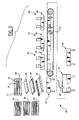
- FIG. 3 is a schematic view of a production-line arrangement for manufacturing the headliner assembly
- FIG. 4 is a cross-sectional view of a blank used to manufacture the headliner assembly, wherein the blank is supported by a frame;
- FIG. 5 is a top view of a headliner assembly showing modified beam structure according to the present invention.
- FIG. 6 is a perspective view of the mold having recesses for forming the foam beams shown on the headliner of FIG. 5 ;
- FIG. 7 is a sectional view taken substantially along the line 7 - 7 in FIG. 5 ;
- FIG. 8 is a view of a vehicle overhead system incorporating a headliner assembly in accordance with an embodiment of the present invention.
- FIG. 9 is a bottom perspective view of a headliner assembly in accordance with another embodiment of the present invention.
- the backing layer 16 is preferably a relatively stiff, semi-flexible scrim layer, and has a first or upper surface 22 that is positioned proximate the interior surface of the roof 11 of the vehicle, and a second or lower surface 24 .
- the substrate layer 18 is attached to the lower surface 20 of the backing layer 16 , such as with an adhesive. Nevertheless, changes in the structure forming the substrate 18 are also within the scope of the present invention.
- the substrate layer 18 preferably comprises a thermoformable rigid urethane layer sandwiched between two fiberglass layers.
- the cover layer 20 may be any suitable cover material, such as cloth, vinyl or foam backed leather, and provided with or without a padding layer depending upon the use characteristics required.
- the cover layer 20 is attached to the substrate layer 18 , preferably with an adhesive.
- the headliner assembly 12 may be manufactured without a backing layer 16 and/or a cover layer 20 if not required for a particular application.
- the front beam 13 , mid beam 14 , rear beam 15 and side beams 17 and 19 may be disposed proximate or inwardly of peripheral portions of the roof 11 when the headliner assembly 10 is mounted to the roof 11 .
- the beams 17 and 19 are disposed proximate side rails 26 of the roof 11 when the headliner assembly 10 is mounted to the roof 11 , such that the beams are positioned interiorly of the side rails 26 .
- the number of beams, and the size and shape of each beam may be varied depending on the application. Nevertheless, at least one of the beams, for example, mid beam 14 , includes a mid portion 84 that borders a selected component area.
- the beams 13 , 14 and 15 are made of a foam that may be energy absorptive but other compositions are also within the scope of the present invention. While the foam may comprise any suitable material, in a preferred embodiment illustrated, the foam comprises a mixture of isocyanate and resin, which is polyurethane commercially available from several sources.
- the beams 13 , 14 , 15 , 17 and 19 are molded directly onto the backing layer 16 such that the beams are simultaneously formed and joined to the backing layer 16 in a single operation, which is described below in greater detail. Alternatively, the beams may be molded directly onto the substrate layer 18 if the backing layer. 16 is eliminated.
- the beams 13 , 14 , and 15 are joined by forming in one piece with the side beams 17 and 19 .
- Such an arrangement forms a frame 25 of structural foam that rigidifies the entire headliner assembly.
- beams according to the invention described in detail below can be formed individually without joining other beams, as desired, without departing from the scope and spirit of the present invention.
- at least one beam is formed to include a selected area surrounded by the foam forming the beam.
- FIG. 3 shows a, production line arrangement 28 according to the invention for forming the headliner assembly 10 .
- the production-line arrangement 28 includes a component storage area 30 , a loading station 32 , a heating station 34 , a forming station. 36 , a foam-in-place molding station 38 , a cutting station 40 , and a fixture installation station 42 .
- the production-line arrangement 28 further includes a conveyor system 43 , such as a chain conveyor, for transporting components between the loading station 32 , the heating station 34 and the forming station 36 .
- the component storage area 30 preferably includes a source 44 of blanks 45 , wherein each blank 45 comprises a substrate layer 18 with a backing layer 16 attached thereto.
- the component storage area 30 further includes a plurality of sources 46 , 48 and 50 of cover layers, wherein each cover layer source 46 , 48 and 50 contains cover layers that are different in color and/or composition compared with another of the cover layer sources 46 , 48 and 50 .
- a blank 45 and a particular cover layer 20 selected from one of the cover layer sources 46 , 48 and 50 are positioned in a transport frame 51 ( FIG. 4 ).
- the frame 51 is then mounted on the conveyor system 43 .
- An adhesive layer may also be positioned between the blank 45 and the cover layer 20 at station 32 .
- the backing layer 16 of the blank 45 of the preferred embodiment preferably has an extended portion 53 that-extends beyond the substrate layer 18 of the blank 45 .
- the transport frame 51 grips the extended portion 53 to thereby support the blank 45 and the cover layer 20 on the conveyor system 43 .
- a conveyor system may be provided with upper and lower chains that grip the extended portion 53 therebetween.
- the substrate layer 18 of the blank 45 may be appropriately sized to closely match the final size or outline of the headliner assembly 10 , to thereby reduce scrap or waste material. Of course, other transports may be used without departing from the invention.
- the blank 45 and the cover layer 20 are then transferred by the conveyor system 43 to the heating station 34 shown in FIG. 4 .
- the heating station 34 includes a platen assembly 54 having upper and lower heated platens that engage the blank 45 and the cover layer 20 to thereby heat the blank 45 and the cover layer 20 .
- the platen assembly 54 also has a plurality of thermocouples for sensing temperature of the blank 45 and the cover layer 20 . Once sufficiently heated, the blank 45 and the cover layer 20 are transferred by the conveyor system 43 to the forming station 36 .
- the forming station 36 includes a first mold 56 having first and second mold portions for thermoforming the blank 45 and the cover layer 20 to form the-main body 12 , such that the main body 12 has a shape that corresponds to a desired shape of the headliner assembly 10 .
- both mold portions may also be chilled in any suitable manner, such as by circulating chilled fluid, such as water through the mold portions.
- the forming station 36 preferably includes multiple molds, similar to the first mold 56 , that can be alternately used to form different headliner shapes and sizes.
- the main body 12 is then transported manually or otherwise to the foam-in-place molding station 38 .
- the lower mold portion 62 includes a plurality of cavities or recesses 68 , 70 , 72 , 73 and 75 for respectively forming the beams 13 , 14 , 15 , 17 and 19 .
- Each of the recesses may be in fluid communication with one or more pour heads 74 that inject or otherwise introduce foam into the particular recess 68 , 70 , 72 , 73 and 75 .
- each of the recesses is in fluid communication with at least one pour head 74 , particularly if the recesses are separated from each other.
- Each of the recesses may also be in fluid communication with two or more pour heads 74 .
- a single nozzle or pour head may introduce the foam into the recess. Nevertheless, multiple pour heads may be used to expedite the introduction of foam to the mold 58 .
- the pour heads 74 are connected to one or more sources of foam (not shown), such as a mixture of isocyanate and resin.
- the formed main body 12 is positioned between the mold portions 60 and 62 , and the mold portions 60 and 62 are closed together.
- foam is injected by the pour heads 74 into the recesses 68 , 70 , 72 , 73 and 75 .
- foam may preferably be first injected into the recesses 73 and 75 , and subsequently into the recesses 68 when multiple nozzles are not available. As a result, expansion and curing of the foam may be arranged to conclude in all of the recesses at approximately the same time.
- the lower mold portion 62 may also be heated preferably in the range of 130° F. to 190° F. for isocyanate and resin to assist in the expansion and curing process of the foam, and to flash off water that may be associated with a mold-release agent applied to the mold parts such as sprayed on wax for an injection molding operation.
- the multiple pour heads feeding a particular one of the larger recesses may preferably inject foam simultaneously, or in closely spaced stages, so as to provide relatively consistent foam characteristics throughout.
- the mid beam 14 includes a mid bar 84 that includes diverging beam portions that form or surround a component area 86 within the headliner. This is formed by an intermediate wall that diverges the fluid foam to border a selected component area.
- the beam provides structural support for and around an accessory component such as a dome light, which may be installed above the headliner. Such a beam protects the accessory or permits mounting to the headliner by the surrounds or partially enclosed walls, without requiring separate construction or assembly after formation of the headliner.
- the quantity or mass of foam per unit of recess volume delivered by the pour heads 74 can be varied from one to another of the recesses so as to vary the density of the resultant beams.
- injection density of the pour heads 74 can be varied from one to another of the recesses so as to vary the density of the resultant beams.
- foam density can be increased in areas requiring greater strength, such as areas of the headliner assembly 10 that will be remote from a side rail or roof supporting A-pillar joints of a motor vehicle.
- foam densities can be decreased in areas requiring less strength so that overall material costs can be significantly reduced.
- Different foam compositions may also be used under the method according to the invention to form beams having different densities.
- the headliner assembly 10 may be precisely formed to achieve relatively close design tolerances with significantly fewer steps and assembly procedures. Because beams are not individually handled and stored, this method involves lower inventory, lower assembly costs and part handling costs compared with prior methods that separately form and install separate support structures and beams.
- components such as wiring harnesses, preformed foam components such as head impact energy absorbing, for example, pads meeting code standards such as FMVSS 201.a, foam cushions, or other accessories, may also form the intermediate wall.
- Components to be installed in the headliner may be positioned within the recesses in the cavity or shaped surface, of the female mold half as shown in FIG. 5 , for embedding the component partially or completely in the beams formed in the mold,
- a wiring harness may be positioned in a predetermined location with respect to functional components to be installed after construction of the headliner.
- the wiring harness 90 as shown in FIG.
- the harness 90 extends into the component area 86 so that any component installed above or carried by the headliner may be provided with electrical power through the harness 90 .
- the other end of the harness 90 is positioned for easy access to a power source or other coupling or connector in the electrical system, and may be made accessible to sources, coupling components or the like by cutting of the headliner assembly after the molding operation, for example, at cutting station 40 discussed below.
- the method of constructing the foam beams also serves to embed and mount accessory components such as a wiring harness, energy absorbing member or other vehicle accessory components.
- a plastic tube, for use as a rear window washer conduit can be embedded in the foam.
- the mold may include a dedicated recess that receives the coupling and protects it when the mold is closed.
- a separate foam-pad such as overhead pad 96
- the pad 96 may be made of an acoustic foam that is absorbent-of acoustic waves in the range of 0 hertz to 10,000 hertz.
- the mold may be modified to include additional channels 94 , in fluid communication with or independent of the beam forming recesses, that are filled during the molding operation at workstation 38 .
- additional channels 94 in fluid communication with or independent of the beam forming recesses, that are filled during the molding operation at workstation 38 .
- These produce a foam pad mounted at selected locations to the headliner providing acoustic control or protecting against buzzes, squeaks and rattles as shown at 96 as predetermined to be desired.
- the pads may be secured to a main body 12 or other components of the headliner.
- the noise reduction pads may also be formed in recesses in fluid communication with channels for forming the foam beam so as to be made with the same pour heads used to inject foam into the beam forming channels.
- the noise reduction pads are made from an acoustically absorbent foam, and may be smaller, thinner and :thus less, bulky than other portions of the structural beams, particularly when formed adjacent to, or within a peripheral frame formed by foam beams.
- a computer controlled, water jet cutting device 80 trims the headliner assembly 10 . Trimming may include cutting openings through the headliner assembly 10 , for example, within the component area 86 or for communication or access to the couplers or terminals of the embedded wiring.
- the rigidity and dimensional stability is preferably closely matched to the final size or outline of the headliner assembly 10 so that the amount of trimming required is significantly reduced compared with prior methods of forming headliners.
- the headliner assembly 10 is then transferred to the fixture assembly station 42 where installation of such fixtures as coat hooks, dome lights, wire couplings and ornaments is completed.
- the headliner blank may also be trimmed before molding and foam introduction, particularly when couplings may be protected within the headliner during molding.
- the overhead system 150 includes a rear window wiper and washer system 154 and an NVH pad 156 .
- the window washer system 154 directs washer fluid 158 to spray across a rear window 160 of the vehicle 162 and utilizes a conventional style wiper 164 to clear and clean the window 160 .
- the NVH pad 156 minimizes noises and kinetic energy experienced within the interior cabin 166 of the vehicle 162 .
- the window washer system 154 includes a washer fluid line 168 , which extends across a headliner structure 170 of the headliner assembly 152 .
- the washer fluid line 168 as well as the tabs 172 of the NVH pad 156 are embedded within foam beams 174 of the headliner structure 170 .
- the headliner structure 170 thus supports the washer fluid line 168 and the NVH pad 156 .
- the window washer system 154 includes a washer fluid reservoir 180 containing the washer fluid 158 .
- the washer fluid 158 is directed through the washer fluid line 168 via a pump 182 to the rear window 160 .
- the washer fluid line 168 may be directed into the wiper 164 .
- the wiper 164 is operated via a wiper motor 184 .
- the washer fluid line 168 extends up an A-pillar 186 of the vehicle 162 through the headliner assembly 152 and down a rear or C-pillar 188 of the vehicle 162 to the wiper 164 .
- the washer fluid line 168 may be of various types and styles and may be formed of various materials known in the art. Although a single washer fluid line is shown, any number of which may be utilized.
- the NVH pad 156 may also be formed of various materials.
- the NVH pad 156 may, for example, be formed of rubber, adhesive materials, foam, mastic materials, plastic materials, viscoelastic materials, other materials known in the art, or a combination thereof.
- the NVH pad 156 may be in the form of a pressed filter board, a fibrous lint-like sheet of material, or may be in some other form. As with the washer fluid line, any number of NVH pads may be utilized.
- the NVH pad 156 is supported by the headliner structure 170 via the tabs 172 .
- the tabs 172 are embedded within the foam beams 174 during formation thereof.
- the tabs 172 are shown as one example of embedding portions of the NVH pad 156 within the foam beams 174 , other portions of the NVH pad 156 may be embedded within the foam beams 174 .
- the tabs 172 may be formed of the same or different material as that of the NVH pad 156 .
- the tabs 172 may be an integral part of the NVH pad 156 or may be separate and attached to the NVH pad 156 .
- FIG. 9 a bottom perspective view of a headliner assembly 152 ′ having a sunroof opening 200 in accordance with another embodiment of the present invention is shown.
- the headliner assembly 152 ′ includes a washer fluid line 168 ′ and one or more NVH pads 156 ′, which are at least partially embedded within the foam beams 174 ′.
- the foam beams 174 ′ include a front beam 202 , a first mid-beam 204 , a second mid-beam 206 , and a pair of rear beam sections 208 .
- the washer fluid line 168 ′ extends along a passenger or right side 210 of the headliner assembly 152 ′.
- a first NVH pad 212 is shown between the second mid-beam 206 and the rear sections 208 .
- a second NVH pad may be utilized between the front beam 202 and the first-mid beam 204 , as is designated and shown by dashed lines 214 .
- the NVH pads 156 ′ may cover any amount of cross-sectional surface area of the headliner assembly 152 ′.
- a washer fluid line of the headliner assembly 152 ′′ such as shown by lines 222 , may be applied, held, or attached to the headliner assembly 152 ′′ or to a recess 224 of the mold portion 220 prior to positioning of the headliner assembly 152 ′′ over the mold portion 220 for formation of the foam beams 174 ′′.
- the washer fluid line may be applied, attached, or held via alignment pins 226 or the like as suggested above.
- the alignment devices 226 may be of-various types, styles, and sizes and may be formed or various materials known in the art.
- the alignment devices 226 may be coupled to the headliner assembly 152 ′′ or to a headliner structure or main body thereof or to the mold portion 220 and are use to maintain position of the washer fluid line during formation of the foam beams 174 ′′. Upon formation and curing of the foam beams 174 ′′ the alignment devices 226 may remain in the headliner assembly 152 ′′ or may be removed.
- the alignment devices 226 are shown as alignment pins, other alignment devices may be utilized, such as alignment tabs, clips, straps, or other devices that may be used to maintain position of the washer fluid line.
- the alignment devices 226 may also be utilized to maintain the alignment of NVH pads, such as the NVH pad 228 , contained within the headliner assembly 152 ′′.
- the alignment devices 226 may also be utilized to form a location for a washer fluid line.
- the washer fluid line may be placed between the alignment devices 226 and held in place such that foam may surround and encase the washer fluid line.
- the alignment devices 226 may also aid in the alignment of the washer fluid line, for example, along the recess of the mold portion 220 .
Abstract
Description
Claims (8)
Priority Applications (3)
| Application Number | Priority Date | Filing Date | Title |
|---|---|---|---|
| US10/862,219 US7309521B2 (en) | 2002-12-19 | 2004-06-07 | Headliner apparatus with foam imbedded NVH pad |
| GB0511509A GB2414959B (en) | 2004-06-07 | 2005-06-07 | Headliner apparatus with foam imbedded nvh pad |
| DE200510026237 DE102005026237A1 (en) | 2004-06-07 | 2005-06-07 | Headliner with foamed-in NVH padding |
Applications Claiming Priority (2)
| Application Number | Priority Date | Filing Date | Title |
|---|---|---|---|
| US10/324,444 US6939491B2 (en) | 2002-02-18 | 2002-12-19 | Foam in place urethane for structural headliners |
| US10/862,219 US7309521B2 (en) | 2002-12-19 | 2004-06-07 | Headliner apparatus with foam imbedded NVH pad |
Related Parent Applications (1)
| Application Number | Title | Priority Date | Filing Date |
|---|---|---|---|
| US10/324,444 Continuation-In-Part US6939491B2 (en) | 2002-02-18 | 2002-12-19 | Foam in place urethane for structural headliners |
Publications (2)
| Publication Number | Publication Date |
|---|---|
| US20040222673A1 US20040222673A1 (en) | 2004-11-11 |
| US7309521B2 true US7309521B2 (en) | 2007-12-18 |
Family
ID=34839051
Family Applications (1)
| Application Number | Title | Priority Date | Filing Date |
|---|---|---|---|
| US10/862,219 Expired - Fee Related US7309521B2 (en) | 2002-12-19 | 2004-06-07 | Headliner apparatus with foam imbedded NVH pad |
Country Status (3)
| Country | Link |
|---|---|
| US (1) | US7309521B2 (en) |
| DE (1) | DE102005026237A1 (en) |
| GB (1) | GB2414959B (en) |
Cited By (8)
| Publication number | Priority date | Publication date | Assignee | Title |
|---|---|---|---|---|
| US20060103172A1 (en) * | 2004-11-18 | 2006-05-18 | Johnson Controls Technology Company | Frame for a panel in a vehicle |
| US20120025567A1 (en) * | 2009-04-07 | 2012-02-02 | Toyota Jidosha Kabushiki Kaisha | Passenger compartment material structure |
| US20120104784A1 (en) * | 2009-04-09 | 2012-05-03 | Johnson Controls Technology Company | Trim panel for a vehicle |
| US8387257B2 (en) | 2010-09-01 | 2013-03-05 | Ford Global Technologies, Llc | Vehicle interior panel and method to manufacture |
| US9022461B2 (en) * | 2013-05-03 | 2015-05-05 | Daehan Solutions Co., Ltd. | High stiffness waterproof roof panel pad for vehicle and manufacturing method thereof |
| US9428130B2 (en) | 2012-06-05 | 2016-08-30 | Bayerische Motoren Werke Aktiengesellschaft | Roof for a motor vehicle |
| US9457738B2 (en) | 2014-09-18 | 2016-10-04 | Ford Global Technologies, Llc | Energy absorbers for roof system and other vehicle structures |
| US9969442B1 (en) | 2016-12-16 | 2018-05-15 | Honda Motor Co., Ltd. | Vehicle body frame including structural bulkhead with acoustic spray foam control |
Families Citing this family (7)
| Publication number | Priority date | Publication date | Assignee | Title |
|---|---|---|---|---|
| US7309521B2 (en) * | 2002-12-19 | 2007-12-18 | International Automotive Components Group North America, Inc. | Headliner apparatus with foam imbedded NVH pad |
| JP2007022126A (en) * | 2005-07-12 | 2007-02-01 | Beat Sonic:Kk | Pillar cover |
| DE102006005369B3 (en) * | 2006-02-03 | 2007-07-19 | Carcoustics Tech Center Gmbh | Sound-absorbing shaped articles, e.g. automobile carpet underlays, based on recycled materials, are obtained by pressing sheet of mixture of fusible fibers, foam particles and heavy layered particles in mold |
| US7798566B2 (en) * | 2007-12-14 | 2010-09-21 | Toyota Motor Engineering & Manufacturing North America, Inc. | Molded headliner reinforcement |
| EP2385910B2 (en) * | 2009-01-06 | 2023-03-15 | Johnson Controls Technology Company | Headliner with integral wire harness |
| US8262156B2 (en) * | 2010-08-30 | 2012-09-11 | Toyota Motor Engineering & Manufacturing North America, Inc. | Wire harness guide and protector |
| DE102018205733A1 (en) * | 2018-04-16 | 2019-10-17 | Magna Exteriors (Bohemia) s.r.o. | Method for producing a reinforcing component and component |
Citations (19)
| Publication number | Priority date | Publication date | Assignee | Title |
|---|---|---|---|---|
| EP0411376A1 (en) | 1989-08-04 | 1991-02-06 | FIAT AUTO S.p.A. | Panel, in particular for vehicle doors and relative method of manufacture |
| JPH08113096A (en) | 1994-10-14 | 1996-05-07 | Kasai Kogyo Co Ltd | Pillar garnish attaching structure |
| JPH1016688A (en) | 1996-06-28 | 1998-01-20 | Inoac Corp | Interior material of automobile |
| US5976295A (en) | 1996-08-30 | 1999-11-02 | Chrysler Corporation | Method of molding a recyclable multi-layer component from plastics material |
| DE19958374A1 (en) | 1998-12-07 | 2000-06-08 | Sai Automotive Ind Nanterre | Sound absorptive cladding element for motor vehicles comprises one-piece foam block to encase part of enclosed absorbing elements in block recess |
| US6120090A (en) | 1997-02-21 | 2000-09-19 | Lear-Donnelly Overhead Systems, L.L.C. | Structural headliner |
| EP1038649A2 (en) | 1999-03-25 | 2000-09-27 | Lear Corporation | Method and apparatus for forming headliners |
| US6204209B1 (en) | 1998-04-10 | 2001-03-20 | Johnson Controls Technology Company | Acoustical composite headliner |
| US20010046587A1 (en) | 1998-12-21 | 2001-11-29 | Raj S. Michael | Encapsulated self adhering acoustic mat for sandwich used in vehicle interior systems |
| US20020001706A1 (en) | 1998-10-13 | 2002-01-03 | Oji Paper Co., Ltd. | Automobile interior headliner molding or forming member and an automobile interior headliner member using the same |
| US6413613B1 (en) | 1999-08-27 | 2002-07-02 | Lear Corporation | Automotive headliners and related articles |
| US6475937B1 (en) | 2000-03-17 | 2002-11-05 | Patent Holding Company | Lightweight, thermoplastic, vehicle headliner having at least one integrally-formed, energy-absorbing, head-impact mechanism and injection molding method for making same |
| US20030026968A1 (en) | 2001-07-25 | 2003-02-06 | Oji Interpack Co., Ltd. | Automobile interior headliner molding or forming member and automobile interior headliner member using the same |
| US20030044580A1 (en) | 1999-10-14 | 2003-03-06 | Gorowlcz Janusz P. | Headliner having integrated energy absorbing foam |
| US6555042B1 (en) | 1998-07-24 | 2003-04-29 | Lear Corporation | Method of making a vehicle headliner assembly with integral speakers |
| US6685262B1 (en) * | 2003-03-26 | 2004-02-03 | Lear Corporation | Foam in place integral air duct |
| US6776944B2 (en) * | 1999-05-28 | 2004-08-17 | Textron Automotive Company Inc. | Method for applying BSR elastomer |
| US20040222673A1 (en) | 2002-12-19 | 2004-11-11 | Brown Bari W. | Headliner apparatus with foam imbedded NVH pad |
| US6939491B2 (en) * | 2002-02-18 | 2005-09-06 | Lear Corporation | Foam in place urethane for structural headliners |
-
2004
- 2004-06-07 US US10/862,219 patent/US7309521B2/en not_active Expired - Fee Related
-
2005
- 2005-06-07 GB GB0511509A patent/GB2414959B/en not_active Expired - Fee Related
- 2005-06-07 DE DE200510026237 patent/DE102005026237A1/en not_active Withdrawn
Patent Citations (21)
| Publication number | Priority date | Publication date | Assignee | Title |
|---|---|---|---|---|
| EP0411376A1 (en) | 1989-08-04 | 1991-02-06 | FIAT AUTO S.p.A. | Panel, in particular for vehicle doors and relative method of manufacture |
| JPH08113096A (en) | 1994-10-14 | 1996-05-07 | Kasai Kogyo Co Ltd | Pillar garnish attaching structure |
| JPH1016688A (en) | 1996-06-28 | 1998-01-20 | Inoac Corp | Interior material of automobile |
| US5976295A (en) | 1996-08-30 | 1999-11-02 | Chrysler Corporation | Method of molding a recyclable multi-layer component from plastics material |
| US6120090A (en) | 1997-02-21 | 2000-09-19 | Lear-Donnelly Overhead Systems, L.L.C. | Structural headliner |
| US6204209B1 (en) | 1998-04-10 | 2001-03-20 | Johnson Controls Technology Company | Acoustical composite headliner |
| US6555042B1 (en) | 1998-07-24 | 2003-04-29 | Lear Corporation | Method of making a vehicle headliner assembly with integral speakers |
| US20020001706A1 (en) | 1998-10-13 | 2002-01-03 | Oji Paper Co., Ltd. | Automobile interior headliner molding or forming member and an automobile interior headliner member using the same |
| US6655730B2 (en) | 1998-10-13 | 2003-12-02 | Oji Paper Co., Ltd. | Automobile interior headliner molding or forming member and an automobile interior headliner member using the same |
| DE19958374A1 (en) | 1998-12-07 | 2000-06-08 | Sai Automotive Ind Nanterre | Sound absorptive cladding element for motor vehicles comprises one-piece foam block to encase part of enclosed absorbing elements in block recess |
| US20010046587A1 (en) | 1998-12-21 | 2001-11-29 | Raj S. Michael | Encapsulated self adhering acoustic mat for sandwich used in vehicle interior systems |
| EP1038649A2 (en) | 1999-03-25 | 2000-09-27 | Lear Corporation | Method and apparatus for forming headliners |
| US6776944B2 (en) * | 1999-05-28 | 2004-08-17 | Textron Automotive Company Inc. | Method for applying BSR elastomer |
| US6413613B1 (en) | 1999-08-27 | 2002-07-02 | Lear Corporation | Automotive headliners and related articles |
| US20030044580A1 (en) | 1999-10-14 | 2003-03-06 | Gorowlcz Janusz P. | Headliner having integrated energy absorbing foam |
| US20030021956A1 (en) | 2000-03-17 | 2003-01-30 | Patent Holding Company | Method for making a lightweight, thermoplastic, vehicle headliner having at least one integrally formed, energy-absorbing, head-impact mechanism |
| US6475937B1 (en) | 2000-03-17 | 2002-11-05 | Patent Holding Company | Lightweight, thermoplastic, vehicle headliner having at least one integrally-formed, energy-absorbing, head-impact mechanism and injection molding method for making same |
| US20030026968A1 (en) | 2001-07-25 | 2003-02-06 | Oji Interpack Co., Ltd. | Automobile interior headliner molding or forming member and automobile interior headliner member using the same |
| US6939491B2 (en) * | 2002-02-18 | 2005-09-06 | Lear Corporation | Foam in place urethane for structural headliners |
| US20040222673A1 (en) | 2002-12-19 | 2004-11-11 | Brown Bari W. | Headliner apparatus with foam imbedded NVH pad |
| US6685262B1 (en) * | 2003-03-26 | 2004-02-03 | Lear Corporation | Foam in place integral air duct |
Cited By (10)
| Publication number | Priority date | Publication date | Assignee | Title |
|---|---|---|---|---|
| US20060103172A1 (en) * | 2004-11-18 | 2006-05-18 | Johnson Controls Technology Company | Frame for a panel in a vehicle |
| US20120025567A1 (en) * | 2009-04-07 | 2012-02-02 | Toyota Jidosha Kabushiki Kaisha | Passenger compartment material structure |
| US8474904B2 (en) * | 2009-04-07 | 2013-07-02 | Toyota Jidosha Kabushiki Kaisha | Passenger compartment material structure |
| US20120104784A1 (en) * | 2009-04-09 | 2012-05-03 | Johnson Controls Technology Company | Trim panel for a vehicle |
| US8387257B2 (en) | 2010-09-01 | 2013-03-05 | Ford Global Technologies, Llc | Vehicle interior panel and method to manufacture |
| US9428130B2 (en) | 2012-06-05 | 2016-08-30 | Bayerische Motoren Werke Aktiengesellschaft | Roof for a motor vehicle |
| US9022461B2 (en) * | 2013-05-03 | 2015-05-05 | Daehan Solutions Co., Ltd. | High stiffness waterproof roof panel pad for vehicle and manufacturing method thereof |
| US9457738B2 (en) | 2014-09-18 | 2016-10-04 | Ford Global Technologies, Llc | Energy absorbers for roof system and other vehicle structures |
| US9969442B1 (en) | 2016-12-16 | 2018-05-15 | Honda Motor Co., Ltd. | Vehicle body frame including structural bulkhead with acoustic spray foam control |
| US10472001B2 (en) | 2016-12-16 | 2019-11-12 | Honda Motor Co., Ltd. | Vehicle body frame including structural bulkhead with acoustic spray foam control |
Also Published As
| Publication number | Publication date |
|---|---|
| GB0511509D0 (en) | 2005-07-13 |
| US20040222673A1 (en) | 2004-11-11 |
| DE102005026237A1 (en) | 2006-01-12 |
| GB2414959B (en) | 2007-01-17 |
| GB2414959A (en) | 2005-12-14 |
Similar Documents
| Publication | Publication Date | Title |
|---|---|---|
| GB2414959A (en) | Vehicle headliner with pad embedded in foam | |
| US6409947B1 (en) | Blow molded headliner | |
| US6500369B1 (en) | Method of making a headliner having integrated energy absorbing foam | |
| EP1038649B1 (en) | Method and apparatus for forming headliners | |
| US20020066972A1 (en) | Integrated soft pads for one step molded parts | |
| US20010001687A1 (en) | Fiber-reinforced vehicle interior trim and method of manufacture | |
| US6685262B1 (en) | Foam in place integral air duct | |
| US4892770A (en) | Interior trim foam product and method of fabrication thereof | |
| EP0288130A2 (en) | Interior trim foam product and method of fabrication thereof | |
| US6939491B2 (en) | Foam in place urethane for structural headliners | |
| US20040222672A1 (en) | Headliner apparatus with foam imbedded washer fluid line | |
| US5318822A (en) | Hollow core instrument panel | |
| US20040119184A1 (en) | Method for foaming in place headliner structures | |
| US20050258668A1 (en) | Automotive headliner having impact countermeasures and method for making the same | |
| WO2013077003A1 (en) | Automobile interior/exterior finishing material and method for manufacturing same | |
| US7063183B2 (en) | Apparatus and methods of forming sound attenuating laminates having fiber and mass layers | |
| JP2003326941A (en) | Duct and its molding method | |
| JP2003306025A (en) | Duct and molding method therefor | |
| JP4085310B2 (en) | Duct and forming method thereof | |
| US20030189271A1 (en) | Method of making a door panel having a decorative insert | |
| JP2003300417A (en) | Vehicle door trim | |
| JPH08113091A (en) | Rear parcel shelf for automobile | |
| JPH07266433A (en) | Automotive interior trim and manufacture thereof | |
| Mazzoni | Headliner, Door Panel, Sound Absorption and Window Encapsulation-Automatic Turnkey Processes | |
| KR20050061010A (en) | Method for forming the interial materials of automobile |
Legal Events
| Date | Code | Title | Description |
|---|---|---|---|
| AS | Assignment |
Owner name: LEAR CORPORATION, MICHIGAN Free format text: ASSIGNMENT OF ASSIGNORS INTEREST;ASSIGNOR:BROWN, BARI W.;REEL/FRAME:015441/0118 Effective date: 20040602 |
|
| AS | Assignment |
Owner name: JPMORGAN CHASE BANK, N.A., AS GENERAL ADMINISTRATI Free format text: SECURITY AGREEMENT;ASSIGNOR:LEAR CORPORATION;REEL/FRAME:017858/0719 Effective date: 20060425 |
|
| AS | Assignment |
Owner name: INTERNATIONAL AUTOMOTIVE COMPONENTS GROUP NORTH AM Free format text: ASSIGNMENT OF ASSIGNORS INTEREST;ASSIGNOR:LEAR CORPORATION;REEL/FRAME:019215/0727 Effective date: 20070427 |
|
| AS | Assignment |
Owner name: GENERAL ELECTRIC CAPITAL CORPORATION, AS AGENT, CO Free format text: SECURITY INTEREST;ASSIGNOR:INTERNATIONAL AUTOMOTIVE COMPONENTS GROUP NORTH AMERICA, INC;REEL/FRAME:025845/0193 Effective date: 20101110 Owner name: GENERAL ELECTRIC CAPITAL CORPORATION, AS AGENT, CO Free format text: SECURITY AGREEMENT;ASSIGNOR:INTERNATIONAL AUTOMOTIVE COMPONENTS GROUP NORTH AMERICA, INC.;REEL/FRAME:025882/0019 Effective date: 20101110 |
|
| XAS | Not any more in us assignment database |
Free format text: SECURITY INTEREST;ASSIGNOR:INTERNATIONAL AUTOMOTIVE COMPONENTS GROUP NORTH AMERICA, INC;REEL/FRAME:025845/0193 |
|
| REMI | Maintenance fee reminder mailed | ||
| LAPS | Lapse for failure to pay maintenance fees | ||
| STCH | Information on status: patent discontinuation |
Free format text: PATENT EXPIRED DUE TO NONPAYMENT OF MAINTENANCE FEES UNDER 37 CFR 1.362 |
|
| FP | Lapsed due to failure to pay maintenance fee |
Effective date: 20111218 |
|
| AS | Assignment |
Owner name: LEAR CORPORATION, MICHIGAN Free format text: RELEASE BY SECURED PARTY;ASSIGNOR:JPMORGAN CHASE BANK, N.A.;REEL/FRAME:032722/0553 Effective date: 20100830 |
|
| AS | Assignment |
Owner name: INTERNATIONAL AUTOMOTIVE COMPONENTS GROUP NORTH AM Free format text: RELEASE BY SECURED PARTY;ASSIGNOR:GENERAL ELECTRIC CAPITAL CORPORATION, AS COLLATERAL AGENT;REEL/FRAME:036777/0904 Effective date: 20150930 |
|
| AS | Assignment |
Owner name: LEAR CORPORATION, MICHIGAN Free format text: RELEASE BY SECURED PARTY;ASSIGNOR:JPMORGAN CHASE BANK, N.A., AS AGENT;REEL/FRAME:037731/0918 Effective date: 20160104 |