US7289449B1 - Device and method for managing fault detection and fault isolation in voice and data networks - Google Patents
Device and method for managing fault detection and fault isolation in voice and data networks Download PDFInfo
- Publication number
- US7289449B1 US7289449B1 US09/923,848 US92384801A US7289449B1 US 7289449 B1 US7289449 B1 US 7289449B1 US 92384801 A US92384801 A US 92384801A US 7289449 B1 US7289449 B1 US 7289449B1
- Authority
- US
- United States
- Prior art keywords
- network
- data concentrator
- intelligent data
- head end
- fault detection
- Prior art date
- Legal status (The legal status is an assumption and is not a legal conclusion. Google has not performed a legal analysis and makes no representation as to the accuracy of the status listed.)
- Expired - Lifetime, expires
Links
- 238000001514 detection method Methods 0.000 title claims abstract description 53
- 238000000034 method Methods 0.000 title claims abstract description 44
- 238000002955 isolation Methods 0.000 title abstract description 12
- 238000012545 processing Methods 0.000 claims abstract description 19
- 230000008878 coupling Effects 0.000 claims abstract description 13
- 238000010168 coupling process Methods 0.000 claims abstract description 13
- 238000005859 coupling reaction Methods 0.000 claims abstract description 13
- 238000004891 communication Methods 0.000 claims description 22
- 238000002405 diagnostic procedure Methods 0.000 claims description 4
- 238000000691 measurement method Methods 0.000 claims description 4
- 238000002310 reflectometry Methods 0.000 claims description 4
- 238000012544 monitoring process Methods 0.000 claims description 2
- 238000012423 maintenance Methods 0.000 abstract description 7
- 238000012360 testing method Methods 0.000 description 8
- 238000010586 diagram Methods 0.000 description 6
- 230000008569 process Effects 0.000 description 5
- 230000004044 response Effects 0.000 description 5
- 230000005540 biological transmission Effects 0.000 description 4
- 230000006870 function Effects 0.000 description 3
- 230000036541 health Effects 0.000 description 3
- 230000015654 memory Effects 0.000 description 3
- 239000003795 chemical substances by application Substances 0.000 description 2
- 230000000694 effects Effects 0.000 description 2
- 238000009434 installation Methods 0.000 description 2
- 102100021391 Cationic amino acid transporter 3 Human genes 0.000 description 1
- 101100005280 Neurospora crassa (strain ATCC 24698 / 74-OR23-1A / CBS 708.71 / DSM 1257 / FGSC 987) cat-3 gene Proteins 0.000 description 1
- 108091006230 SLC7A3 Proteins 0.000 description 1
- 238000012631 diagnostic technique Methods 0.000 description 1
- 238000001914 filtration Methods 0.000 description 1
- 230000001939 inductive effect Effects 0.000 description 1
- 230000000977 initiatory effect Effects 0.000 description 1
- 238000011900 installation process Methods 0.000 description 1
- 238000011835 investigation Methods 0.000 description 1
- 230000007246 mechanism Effects 0.000 description 1
- 230000003287 optical effect Effects 0.000 description 1
- 239000000700 radioactive tracer Substances 0.000 description 1
- 238000011084 recovery Methods 0.000 description 1
- 239000000523 sample Substances 0.000 description 1
- 230000011664 signaling Effects 0.000 description 1
- 230000005236 sound signal Effects 0.000 description 1
- 239000000126 substance Substances 0.000 description 1
- 238000011144 upstream manufacturing Methods 0.000 description 1
Images


Classifications
-
- H—ELECTRICITY
- H04—ELECTRIC COMMUNICATION TECHNIQUE
- H04Q—SELECTING
- H04Q3/00—Selecting arrangements
- H04Q3/0016—Arrangements providing connection between exchanges
- H04Q3/0062—Provisions for network management
- H04Q3/0087—Network testing or monitoring arrangements
-
- H—ELECTRICITY
- H04—ELECTRIC COMMUNICATION TECHNIQUE
- H04L—TRANSMISSION OF DIGITAL INFORMATION, e.g. TELEGRAPHIC COMMUNICATION
- H04L12/00—Data switching networks
- H04L12/64—Hybrid switching systems
- H04L12/6418—Hybrid transport
-
- H—ELECTRICITY
- H04—ELECTRIC COMMUNICATION TECHNIQUE
- H04L—TRANSMISSION OF DIGITAL INFORMATION, e.g. TELEGRAPHIC COMMUNICATION
- H04L41/00—Arrangements for maintenance, administration or management of data switching networks, e.g. of packet switching networks
- H04L41/06—Management of faults, events, alarms or notifications
- H04L41/0654—Management of faults, events, alarms or notifications using network fault recovery
- H04L41/0659—Management of faults, events, alarms or notifications using network fault recovery by isolating or reconfiguring faulty entities
-
- H—ELECTRICITY
- H04—ELECTRIC COMMUNICATION TECHNIQUE
- H04L—TRANSMISSION OF DIGITAL INFORMATION, e.g. TELEGRAPHIC COMMUNICATION
- H04L43/00—Arrangements for monitoring or testing data switching networks
- H04L43/08—Monitoring or testing based on specific metrics, e.g. QoS, energy consumption or environmental parameters
- H04L43/0805—Monitoring or testing based on specific metrics, e.g. QoS, energy consumption or environmental parameters by checking availability
- H04L43/0811—Monitoring or testing based on specific metrics, e.g. QoS, energy consumption or environmental parameters by checking availability by checking connectivity
-
- H—ELECTRICITY
- H04—ELECTRIC COMMUNICATION TECHNIQUE
- H04L—TRANSMISSION OF DIGITAL INFORMATION, e.g. TELEGRAPHIC COMMUNICATION
- H04L12/00—Data switching networks
- H04L12/64—Hybrid switching systems
- H04L12/6418—Hybrid transport
- H04L2012/6424—Access arrangements
- H04L2012/6427—Subscriber Access Module; Concentrator; Group equipment
-
- H—ELECTRICITY
- H04—ELECTRIC COMMUNICATION TECHNIQUE
- H04L—TRANSMISSION OF DIGITAL INFORMATION, e.g. TELEGRAPHIC COMMUNICATION
- H04L12/00—Data switching networks
- H04L12/64—Hybrid switching systems
- H04L12/6418—Hybrid transport
- H04L2012/6464—Priority
-
- H—ELECTRICITY
- H04—ELECTRIC COMMUNICATION TECHNIQUE
- H04Q—SELECTING
- H04Q2213/00—Indexing scheme relating to selecting arrangements in general and for multiplex systems
- H04Q2213/13003—Constructional details of switching devices
-
- H—ELECTRICITY
- H04—ELECTRIC COMMUNICATION TECHNIQUE
- H04Q—SELECTING
- H04Q2213/00—Indexing scheme relating to selecting arrangements in general and for multiplex systems
- H04Q2213/13034—A/D conversion, code compression/expansion
-
- H—ELECTRICITY
- H04—ELECTRIC COMMUNICATION TECHNIQUE
- H04Q—SELECTING
- H04Q2213/00—Indexing scheme relating to selecting arrangements in general and for multiplex systems
- H04Q2213/1308—Power supply
-
- H—ELECTRICITY
- H04—ELECTRIC COMMUNICATION TECHNIQUE
- H04Q—SELECTING
- H04Q2213/00—Indexing scheme relating to selecting arrangements in general and for multiplex systems
- H04Q2213/13093—Personal computer, PC
-
- H—ELECTRICITY
- H04—ELECTRIC COMMUNICATION TECHNIQUE
- H04Q—SELECTING
- H04Q2213/00—Indexing scheme relating to selecting arrangements in general and for multiplex systems
- H04Q2213/13098—Mobile subscriber
-
- H—ELECTRICITY
- H04—ELECTRIC COMMUNICATION TECHNIQUE
- H04Q—SELECTING
- H04Q2213/00—Indexing scheme relating to selecting arrangements in general and for multiplex systems
- H04Q2213/13179—Fax, still picture
-
- H—ELECTRICITY
- H04—ELECTRIC COMMUNICATION TECHNIQUE
- H04Q—SELECTING
- H04Q2213/00—Indexing scheme relating to selecting arrangements in general and for multiplex systems
- H04Q2213/13339—Ciphering, encryption, security
-
- H—ELECTRICITY
- H04—ELECTRIC COMMUNICATION TECHNIQUE
- H04Q—SELECTING
- H04Q2213/00—Indexing scheme relating to selecting arrangements in general and for multiplex systems
- H04Q2213/13349—Network management
-
- H—ELECTRICITY
- H04—ELECTRIC COMMUNICATION TECHNIQUE
- H04Q—SELECTING
- H04Q2213/00—Indexing scheme relating to selecting arrangements in general and for multiplex systems
- H04Q2213/13386—Line concentrator
-
- H—ELECTRICITY
- H04—ELECTRIC COMMUNICATION TECHNIQUE
- H04Q—SELECTING
- H04Q2213/00—Indexing scheme relating to selecting arrangements in general and for multiplex systems
- H04Q2213/13389—LAN, internet
Definitions
- the present invention relates to the field of computer networks.
- the present invention relates to a device and a method for fault detection in voice and data networks.
- Installation and maintenance of a network of devices connected by network cabling is typically a labor and time intensive endeavor. If a client device loses the integrity of its connection to the network, an investigation as to what cause the connection loss must be initiated.
- An alternate method is to use a software remote control package enabled by the end user to gain control of the PC operating to allow a remote agent to take control of the client PC.
- Control of the client PC by the IS technician can only be performed after specific direct actions are taken by the end user.
- the IS technician must rely on the user of the client device to install the software remote control package, to accurately follow instructions and relay information to the IS technician. Often, users are not as knowledgeable as the IS technician would require, and a technician must be dispatched to the location of the user.
- the present invention provides a device and method for managing fault detection and isolation in voice and data networks.
- the present invention is a device and method for fault detection and fault isolation that can be used to validate connectivity of a central site to a number of connected client devices.
- the present invention operates stage by stage, working from the central site back to a connected client device.
- the described method can be controlled from a central maintenance station and as such does not require direct end-user enabling.
- the present invention provides an intelligent device (e.g., an intelligent data concentrator) for coupling an electronic device to a network comprising a first interface for communicatively coupling the intelligent device to the network and a second interface for communicatively coupling the intelligent device to a plurality of client devices such that the client devices are communicatively coupled to the network.
- the intelligent device also comprises means for processing and interpreting data coupled to the first interface, and fault detection means coupled to the means for processing and interpreting data, wherein the fault detection means performs fault detection in the network.
- the head end is a central control site operable to remotely access the means for processing and interpreting data of the intelligent data concentrator. By communicating with the intelligent data concentrator, the head end is able to perform fault detection and isolation in the network.
- the fault detection means is configured to isolate faults in both an uplink from the head end of the network and a downlink from the head end of the network.
- the fault detection means is selected from the group consisting essentially of: a link beat signal fault detection, a ping signal fault detection, and a loop-back mode for fault detection.
- the intelligent device is configured such that the intelligent device is provided power over the network. In one embodiment, the intelligent device is configured such that it provides power to connected client devices. In one embodiment, the head end is configured to activate and deactivate the intelligent device over the network. In another embodiment, the intelligent device is configured to activate and deactivate connected client devices.
- the intelligent device employs time domain reflectometry (TDR) measurement techniques such that fault detection means is operable to determine a distance from the intelligent device to the fault.
- TDR time domain reflectometry
- the head end is configured to transmit data packets to the intelligent device such that diagnostic tests can be performed at the intelligent device for validating network connections.
- FIG. 1 illustrates an exemplary wired desktop cluster coupled to a local area network (LAN) in accordance with one embodiment of the present invention.
- LAN local area network
- FIG. 2 is a block diagram of a cross-sectional view of an intelligent data concentrator in accordance with one embodiment of the present invention.
- FIG. 3 is an illustration of a perspective view of an exemplary faceplate of an intelligent data concentrator in accordance with one embodiment of the present invention.
- FIG. 4 is a block diagram of an exemplary LAN upon which embodiments of the present invention may be practiced.
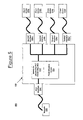
- FIG. 5 is a block diagram of an intelligent data concentrator configured for performing a method of fault detection in accordance with an embodiment of the present invention.
- FIG. 6 is a flowchart of the steps in a process for managing the fault detection in a network in accordance with one embodiment of the present invention.
- Portions of the present invention are comprised of computer-readable and computer executable instructions which reside, for example, in computer-usable media of a computer system. It is appreciated that the present invention can operate within a number of different computer systems including general purpose computer systems, embedded computer systems, and stand alone computer systems specially adapted for controlling automatic test equipment.
- the present invention provides a device and method for managing fault detection and isolation in voice and data networks.
- the present invention is a device and method for fault detection and fault isolation that can be used to validate connectivity of a central site to a number of connected client devices.
- the present invention operates stage by stage, working from the central site back to a connected client device.
- the described method can be controlled from a central maintenance station and as such does not require direct user enabling.
- FIG. 1 illustrates an exemplary personal area network (PAN) 100 coupled to a local area network (LAN) 150 in accordance with one embodiment of the present invention.
- PAN 100 comprises IP telephony 110 , notebook 120 , desktop workstation 130 , and printer 140 , each of which is coupled to intelligent data concentrator 210 .
- Intelligent data concentrator 210 is coupled to LAN 150 , thus acting as an interface from the various client devices (e.g., comprises IP telephony 110 , notebook 120 , desktop workstation 130 , and printer 140 ) to LAN 150 .
- client devices e.g., comprises IP telephony 110 , notebook 120 , desktop workstation 130 , and printer 140
- FIG. 2 is a block diagram 200 of a cross-sectional view of an intelligent data concentrator 210 in accordance with one embodiment of the present invention.
- This embodiment of the present invention implements intelligent hardware that is easy to install and reliably provides an attachment point for access to voice and data networks 240 .
- the embodiment is implemented through miniaturized hardware that can be installed inside of a wall or in internal space provided for in an office cubicle.
- One surface 230 of this embodiment is intended to be accessible by the end user and would in most instances be on an external surface of a workspace.
- a plurality of standard communications ports 220 are mounted on the external surface 230 of this embodiment.
- communication port 220 is an RJ-45 jack.
- communication port 220 is an RJ-11 jack. It should be appreciated that communication port 220 is not limited to any particular jack, and that any type of communication port can be used. Additionally, while intelligent data concentrator 210 illustrates four communication ports 220 , it should be appreciated that alternative implementations could support a greater or lesser number of communication ports 220 .
- Termination of the network cabling 245 will provide for both a reliable electrical and mechanical connection for industry standard communications cabling such as CAT-3, CAT-5, CAT-5E or similar cabling.
- wireless connectivity is a viable method. Infrared (IR), BlueTooth, 802.11 or other means could be utilized to communicate with the device.
- IR Infrared
- BlueTooth 802.11 or other means could be utilized to communicate with the device.
- power for intelligent data concentrator is provided from a central source 250 over the network cabling 245 .
- the present embodiment is also able to forward power to data devices that are connected to communications ports 220 that are on user accessible surface 230 .
- FIG. 3 is an illustration of a perspective view 300 of an exemplary user-accessible surface 230 of an intelligent data concentrator 210 in accordance with one embodiment of the present invention.
- a user is able to connect data devices to a voice or data network through communications ports 220 .
- FIG. 4 is a block diagram of an exemplary LAN 400 upon which embodiments of the present invention may be practiced.
- LAN 400 comprises a head end 405 and intelligent devices 410 , 415 , and 420 .
- intelligent devices 410 , 415 and 420 are intelligent data concentrators (e.g., intelligent data concentrator 210 of FIG. 2 or intelligent data concentrator 502 of FIG. 5 ).
- head end 405 is a central control site that can access the intelligence of intelligent devices 410 , 415 , and 420 .
- head end 405 is a central data switch or hub.
- Intelligent devices 410 , 415 , and 420 are communicatively coupled to head end 405 over links 440 , 445 , and 450 , respectively.
- links 440 , 445 , and 450 are network cabling.
- intelligent devices 410 , 415 , and 420 are connected to head end 405 by means of network cabling.
- network cabling In the current embodiment, CAT 3 or 5 cabling is used and an Ethernet physical interface is employed.
- CAT 3 or 5 cabling is used and an Ethernet physical interface is employed.
- the present invention will work with other types of LANs, such as LANs with differing physical connections or adopted for use in RF wireless and optical systems.
- Intelligent device 410 is coupled to client devices 425 a and 425 b .
- intelligent device 415 is coupled to client devices 430 a , 430 b and 430 c
- intelligent device 420 is coupled to client devices 435 a and 435 b .
- client devices can comprise any number of data devices, including but not limited to: computer systems, printers, voice IP telephones, and fax machines configured for use over voice IP networks.
- FIG. 5 is a block diagram 500 of an intelligent data concentrator 502 configured for performing a method of fault detection in accordance with an embodiment of the present invention.
- Intelligent data concentrator 502 comprises a first interface 504 for communicatively coupling intelligent data concentrator 502 to network 508 .
- Intelligent data concentrator 502 also comprises a plurality of second interfaces 506 a - d for communicatively coupling intelligent data concentrator 502 to a plurality of client devices 510 a - d .
- second interfaces 506 a - d are communication ports (e.g., communication ports 220 of FIG. 2 ). It should be appreciated that there can be any number of second interfaces 506 a - d , and that the present invention is not meant to limit the number of second interfaces 506 a - d .
- First interface 504 operating in conjunction with second interfaces 506 a - d operates to connect client devices 510 a - d to network 508 .
- Intelligent data concentrator 502 also comprises means for processing and interpreting data 512 coupled to the first interface 504 and fault detection means 514 coupled to the means for processing and interpreting data 512 .
- Means for processing and interpreting data 512 is intended to include, but not limited to; a robust processor, a central processing unit (CPU), and a random access memory (RAM).
- Fault detection means 514 is intended to include, but not limited to: a hardware fault detector, a fault detection circuit, a software fault detector, a link beat signal fault detector, a ping signal fault detector, and a loop-back mode for fault detection.
- fault detection means 514 is a fault detector for performing fault detection in a network.
- fault detection means 514 is a software implementation for performing fault detection in a network.
- fault detection means 514 operates in conjunction with a head end (e.g., head end 405 of FIG. 4 ) of network 508 for performing fault detection.
- fault detection means 514 is for performing fault isolation in a network.
- FIG. 6 is a flowchart 600 of the steps in a process for managing the fault detection in a network in accordance with one embodiment of the present invention.
- an intelligent device coupled to a network comprises a first interface for communicatively coupling the intelligent device to a network, a second interface for communicatively coupling the intelligent device to a plurality of client devices, a robust processor coupled to the first interface, and a fault detector coupled to the robust processor.
- the intelligent device is an intelligent data concentrator (e.g., intelligent data concentrator 502 of FIG. 5 ).
- the network has a head end.
- the head end is a central control site that can access the robust processor of the intelligent device.
- the head end is a central data switch or hub.
- the intelligent device and the head end monitor the network for a fault.
- the head end central equipment
- a link beat signal serves as an indication that the physical signaling integrity from the host to the client is intact. If the receiving path from the host to the data concentrator located at the client site fails, the intelligence embedded in the data concentrator could detect the absence of a link beat and initiate a transmission to the network control device indicating that the receive path has failed.
- the address of the network control device could be sent to the client side data concentrator from the central control during the initialization/setup of the concentrator.
- the host can direct a command such as a ping to the intelligent data concentrator to elicit a response from the concentrator.
- a command such as a ping
- the receipt of the response by the host side equipment serves to confirm the integrity of the upstream link.
- faults on either the uplink or downlink can be isolated to a specific segment; this information can be determined at the head end.
- failure can be inferred by the absence of receiving a response to an issued command. Failure can also be inferred by the absence of a message from the controller that it has not heard from the head end. This test case can be initiated by configuring the head end to stop sending the link beat signal and waiting for a fault message from the controller.
- Another method of fault isolation would employ a protocol where the head end switch can issue a command to the intelligence in the invention reversing the role of master and slave would be reversed. With this protocol the lines used to transmit and receive are reversed so the unit could share information over a single healthy channel.
- Another means to aid in the detection of communications faults is to provide a loop-back capability in the physical media interface circuitry.
- data flows from the head end and is received by the client while data intended for the head end is sent over a separate interface and media channel.
- the reception and transmission of data involves circuitry that implements the Media Access Control (MAC) layers of the network protocol as well as the involvement of the Central Processing Unit (CPU) elements.
- MAC Media Access Control
- CPU Central Processing Unit
- the watchdog timer detects and signals this event; this information is used to place the media interface transceivers in loop-back mode.
- loop-back mode information or data received from the host is turned around and placed directly back on the transmitter and returned to the host. The host is able to see that the data is being looped back and that the client side intelligence (MAC, CPU, etc.) has failed.
- the central site can try and reset the intelligent client controller to see if the fault is permanent (hard) or if the problem was transitory in nature. There are several ways to reset the client equipment.
- One method is to have the host remove and reapply the power that is supplied to the client device over the network cable, resulting in a restart of the client logic.
- Another method would be to send a special series of data packets to the client device that can be detected by circuitry such as a state machine and used to generate a reset signal.
- Another way to implement a loop-back/reset sequence is to employ the loop-back mechanism to place the data multiplexor in loop-back mode for a period of time that is sufficient to have the host detect this state and then to self generate a reset signal while maintaining a local status indication that a hang reset sequence has occurred. If the reset revives the controller, the card would then send a message to the host. If the watchdog were to fail again, the card would be left in loop-back mode and the local generation of the reset could be disabled.
- a panel mounted indicator such as an LED
- the health of the concentrator could be determined by physically inspecting the indicator lights or displays.
- the embedded intelligence in the remote data multiplexor is able to employ time domain reflectometry (TDR) measurement techniques to determine whether the cable is intact and to determine the length of the cable. If a fault exists in the cable, the TDR function is able to determine the distance to the fault (open or short). If no faults exist, the length of the entire cable can be determined. This information can be employed to further isolate the source of a failure. For example, if no link beats are being received from the host, it can be determined whether the cable is at fault for the failure. The results of this test can be passed to the host on the uplink from the device to the host. Other standard cable tests (e.g., TIA or BICSI) can be conducted by the present invention with the results shared with the head end through the cabling.
- TDR time domain reflectometry
- a specific dump status/diagnose command is directed to the client which, initiating a transmission from the client side data concentrator, thus running a specific test between the client side concentrator and the local network devices connected to it.
- the data returned to the hosts would contain reports on the health of the network connections further down the chain.
- the ability to run comprehensive tests can enable a network administrator to validate the health of the network and pinpoint faults that may exist from a central point. None of the above techniques preclude or eliminate the older more intrusive diagnostic methods that have been traditionally employed to validate client host networks.
- the physical line that is connected to the uplink is connected to one of the data jacks on the external side.
- the hard cut-through allows installation technicians to run continuity checks through the cabling.
- the cut-through mode allows for a fault tolerant port that continues to function in the absence of power on the data lines.
- Another use for the cut-through mode is to have the previously described watch dog timer/internal diagnostics force this mode if a hard fault in the internal intelligence was detected.
- the unit when power is first applied to the intelligent multiplexor, the unit will repeatedly send out an identification string that contains the device identification (ID) number and unit revision number by placing a harmonic rich signal on the transmit lines.
- the signal is designed to be received by an inductive coupled audio signal tracer. The signal can be heard when the probe is brought in proximity to the line.
- the installer working on connecting the wires to a patch panel can use common tools of the wiring trade to directly receive the device number which will allow the information to be marked without having to communicate or coordinate with the craftsman that installed the invention in the remote work space.
- the method of encoding the signal is to send the information as a series or tone pulses.
- control console could initiate a command message directed to the unit connected to the physical drop to command the device to stop sending the ID sequence.
- the central control console is able to send this command since the port that the device is connected to is known and the internet protocol (IP) address of the drop is assigned to the port on a fixed or Dynamic Host Configuration Protocol (DHCP) basis.
- IP internet protocol
- the head end and the intelligent multiplexor can be established and verified. Testing of the links between the connected client devices can be tested and confirmed.
- the personal area network (PAN) side links can be tested by employing similar techniques as were described above.
- the multiplexor can send a ping or similar command to the device and check for a response.
- the data path through the line drivers to and from the PAN devices can be validated by placing the paths into a local loop-back mode where the internal intelligence can direct data packets through the loop-back physical jack (e.g., a PHY jack).
- the loop-back physical jack e.g., a PHY jack
- the intelligent data multiplexor and the management console After basic connectivity and communications between the central switch, the intelligent data multiplexor and the management console have been established and verified the power feed to the client devices can be activated. Once power is applied, if the amount of current that is drawn ever exceeds a safe limit the power can be removed or limited in a safe manner and the existence of the fault condition can be detected by the intelligence and communicated to a management station.
Abstract
Description
Claims (20)
Priority Applications (2)
| Application Number | Priority Date | Filing Date | Title |
|---|---|---|---|
| US09/923,848 US7289449B1 (en) | 2001-03-20 | 2001-08-06 | Device and method for managing fault detection and fault isolation in voice and data networks |
| PCT/US2002/008470 WO2002091677A2 (en) | 2001-03-20 | 2002-03-19 | Managing fault detection and isolation in voice and data networks |
Applications Claiming Priority (6)
| Application Number | Priority Date | Filing Date | Title |
|---|---|---|---|
| US27759201P | 2001-03-20 | 2001-03-20 | |
| US27759301P | 2001-03-20 | 2001-03-20 | |
| US27776701P | 2001-03-20 | 2001-03-20 | |
| US27745101P | 2001-03-20 | 2001-03-20 | |
| US28541901P | 2001-04-20 | 2001-04-20 | |
| US09/923,848 US7289449B1 (en) | 2001-03-20 | 2001-08-06 | Device and method for managing fault detection and fault isolation in voice and data networks |
Publications (1)
| Publication Number | Publication Date |
|---|---|
| US7289449B1 true US7289449B1 (en) | 2007-10-30 |
Family
ID=27559526
Family Applications (1)
| Application Number | Title | Priority Date | Filing Date |
|---|---|---|---|
| US09/923,848 Expired - Lifetime US7289449B1 (en) | 2001-03-20 | 2001-08-06 | Device and method for managing fault detection and fault isolation in voice and data networks |
Country Status (2)
| Country | Link |
|---|---|
| US (1) | US7289449B1 (en) |
| WO (1) | WO2002091677A2 (en) |
Cited By (148)
| Publication number | Priority date | Publication date | Assignee | Title |
|---|---|---|---|---|
| US20060104206A1 (en) * | 2004-11-18 | 2006-05-18 | Bomhoff Matthew D | Apparatus, system, and method for detecting a fibre channel miscabling event |
| US20060104207A1 (en) * | 2004-11-17 | 2006-05-18 | Tollgrade Communications, Inc. | Apparatus and method of remotely enabling a special mode of operation of an endpoint in a VoIP network |
| US20070140688A1 (en) * | 2005-12-21 | 2007-06-21 | Nortel Networks Limited | Method and apparatus for detecting a fault on an optical fiber |
| US7447813B2 (en) * | 2004-04-01 | 2008-11-04 | Bayerische Motoren Werke Aktiengesellschaft | Method for identifying incompatibilities in a bus system comprising several control devices |
| US7542428B1 (en) * | 2004-01-28 | 2009-06-02 | Cox Communications, Inc. | Geographical network alarm viewer |
| US20090175195A1 (en) * | 2008-01-07 | 2009-07-09 | Commscope, Inc. North Carolina | Methods, systems and computer program products for using time domain reflectometry signatures to monitor network communication lines |
| US20110116387A1 (en) * | 2009-11-16 | 2011-05-19 | Cox Communications, Inc. | Systems and Methods for Locating Power Network Failures on a Network |
| US8295163B1 (en) * | 2007-11-16 | 2012-10-23 | Marvell International Ltd. | Reassigning signals to cable channels |
| US20150347215A1 (en) * | 2012-12-20 | 2015-12-03 | British Telecommunications Public Limited Company | Detection of data connection loss |
| CN105791261A (en) * | 2015-12-28 | 2016-07-20 | 华为技术有限公司 | Detection method and detection device for cross-site scripting attack |
| US9640850B2 (en) | 2015-06-25 | 2017-05-02 | At&T Intellectual Property I, L.P. | Methods and apparatus for inducing a non-fundamental wave mode on a transmission medium |
| US9667317B2 (en) | 2015-06-15 | 2017-05-30 | At&T Intellectual Property I, L.P. | Method and apparatus for providing security using network traffic adjustments |
| US9674711B2 (en) | 2013-11-06 | 2017-06-06 | At&T Intellectual Property I, L.P. | Surface-wave communications and methods thereof |
| US9678133B2 (en) | 2012-03-12 | 2017-06-13 | Commscope, Inc. Of North Carolina | Intelligent patching systems and methods using electrical cable diagnostic tests and inference-based mapping techniques |
| US9685992B2 (en) | 2014-10-03 | 2017-06-20 | At&T Intellectual Property I, L.P. | Circuit panel network and methods thereof |
| US9705610B2 (en) | 2014-10-21 | 2017-07-11 | At&T Intellectual Property I, L.P. | Transmission device with impairment compensation and methods for use therewith |
| US9705561B2 (en) | 2015-04-24 | 2017-07-11 | At&T Intellectual Property I, L.P. | Directional coupling device and methods for use therewith |
| US9722318B2 (en) | 2015-07-14 | 2017-08-01 | At&T Intellectual Property I, L.P. | Method and apparatus for coupling an antenna to a device |
| US9729197B2 (en) | 2015-10-01 | 2017-08-08 | At&T Intellectual Property I, L.P. | Method and apparatus for communicating network management traffic over a network |
| US9735833B2 (en) | 2015-07-31 | 2017-08-15 | At&T Intellectual Property I, L.P. | Method and apparatus for communications management in a neighborhood network |
| US9742521B2 (en) | 2014-11-20 | 2017-08-22 | At&T Intellectual Property I, L.P. | Transmission device with mode division multiplexing and methods for use therewith |
| US9742462B2 (en) | 2014-12-04 | 2017-08-22 | At&T Intellectual Property I, L.P. | Transmission medium and communication interfaces and methods for use therewith |
| US9749013B2 (en) | 2015-03-17 | 2017-08-29 | At&T Intellectual Property I, L.P. | Method and apparatus for reducing attenuation of electromagnetic waves guided by a transmission medium |
| US9749053B2 (en) | 2015-07-23 | 2017-08-29 | At&T Intellectual Property I, L.P. | Node device, repeater and methods for use therewith |
| US9748626B2 (en) | 2015-05-14 | 2017-08-29 | At&T Intellectual Property I, L.P. | Plurality of cables having different cross-sectional shapes which are bundled together to form a transmission medium |
| US9762289B2 (en) | 2014-10-14 | 2017-09-12 | At&T Intellectual Property I, L.P. | Method and apparatus for transmitting or receiving signals in a transportation system |
| US9769020B2 (en) | 2014-10-21 | 2017-09-19 | At&T Intellectual Property I, L.P. | Method and apparatus for responding to events affecting communications in a communication network |
| US9769128B2 (en) | 2015-09-28 | 2017-09-19 | At&T Intellectual Property I, L.P. | Method and apparatus for encryption of communications over a network |
| US9768833B2 (en) | 2014-09-15 | 2017-09-19 | At&T Intellectual Property I, L.P. | Method and apparatus for sensing a condition in a transmission medium of electromagnetic waves |
| US9780834B2 (en) | 2014-10-21 | 2017-10-03 | At&T Intellectual Property I, L.P. | Method and apparatus for transmitting electromagnetic waves |
| US9787412B2 (en) | 2015-06-25 | 2017-10-10 | At&T Intellectual Property I, L.P. | Methods and apparatus for inducing a fundamental wave mode on a transmission medium |
| US9788326B2 (en) | 2012-12-05 | 2017-10-10 | At&T Intellectual Property I, L.P. | Backhaul link for distributed antenna system |
| US9793954B2 (en) | 2015-04-28 | 2017-10-17 | At&T Intellectual Property I, L.P. | Magnetic coupling device and methods for use therewith |
| US9793951B2 (en) | 2015-07-15 | 2017-10-17 | At&T Intellectual Property I, L.P. | Method and apparatus for launching a wave mode that mitigates interference |
| US9793955B2 (en) | 2015-04-24 | 2017-10-17 | At&T Intellectual Property I, Lp | Passive electrical coupling device and methods for use therewith |
| US9800327B2 (en) | 2014-11-20 | 2017-10-24 | At&T Intellectual Property I, L.P. | Apparatus for controlling operations of a communication device and methods thereof |
| US9820146B2 (en) | 2015-06-12 | 2017-11-14 | At&T Intellectual Property I, L.P. | Method and apparatus for authentication and identity management of communicating devices |
| US9838078B2 (en) | 2015-07-31 | 2017-12-05 | At&T Intellectual Property I, L.P. | Method and apparatus for exchanging communication signals |
| US9838896B1 (en) | 2016-12-09 | 2017-12-05 | At&T Intellectual Property I, L.P. | Method and apparatus for assessing network coverage |
| US9847566B2 (en) | 2015-07-14 | 2017-12-19 | At&T Intellectual Property I, L.P. | Method and apparatus for adjusting a field of a signal to mitigate interference |
| US9847850B2 (en) | 2014-10-14 | 2017-12-19 | At&T Intellectual Property I, L.P. | Method and apparatus for adjusting a mode of communication in a communication network |
| US9853342B2 (en) | 2015-07-14 | 2017-12-26 | At&T Intellectual Property I, L.P. | Dielectric transmission medium connector and methods for use therewith |
| US9860075B1 (en) | 2016-08-26 | 2018-01-02 | At&T Intellectual Property I, L.P. | Method and communication node for broadband distribution |
| US9866309B2 (en) | 2015-06-03 | 2018-01-09 | At&T Intellectual Property I, Lp | Host node device and methods for use therewith |
| US9866276B2 (en) | 2014-10-10 | 2018-01-09 | At&T Intellectual Property I, L.P. | Method and apparatus for arranging communication sessions in a communication system |
| US9865911B2 (en) | 2015-06-25 | 2018-01-09 | At&T Intellectual Property I, L.P. | Waveguide system for slot radiating first electromagnetic waves that are combined into a non-fundamental wave mode second electromagnetic wave on a transmission medium |
| US9871558B2 (en) | 2014-10-21 | 2018-01-16 | At&T Intellectual Property I, L.P. | Guided-wave transmission device and methods for use therewith |
| US9871282B2 (en) | 2015-05-14 | 2018-01-16 | At&T Intellectual Property I, L.P. | At least one transmission medium having a dielectric surface that is covered at least in part by a second dielectric |
| US9871283B2 (en) | 2015-07-23 | 2018-01-16 | At&T Intellectual Property I, Lp | Transmission medium having a dielectric core comprised of plural members connected by a ball and socket configuration |
| US9876264B2 (en) | 2015-10-02 | 2018-01-23 | At&T Intellectual Property I, Lp | Communication system, guided wave switch and methods for use therewith |
| US9876571B2 (en) | 2015-02-20 | 2018-01-23 | At&T Intellectual Property I, Lp | Guided-wave transmission device with non-fundamental mode propagation and methods for use therewith |
| US9876605B1 (en) | 2016-10-21 | 2018-01-23 | At&T Intellectual Property I, L.P. | Launcher and coupling system to support desired guided wave mode |
| US9882257B2 (en) | 2015-07-14 | 2018-01-30 | At&T Intellectual Property I, L.P. | Method and apparatus for launching a wave mode that mitigates interference |
| US9887447B2 (en) | 2015-05-14 | 2018-02-06 | At&T Intellectual Property I, L.P. | Transmission medium having multiple cores and methods for use therewith |
| US9893795B1 (en) | 2016-12-07 | 2018-02-13 | At&T Intellectual Property I, Lp | Method and repeater for broadband distribution |
| US9906269B2 (en) | 2014-09-17 | 2018-02-27 | At&T Intellectual Property I, L.P. | Monitoring and mitigating conditions in a communication network |
| US9904535B2 (en) | 2015-09-14 | 2018-02-27 | At&T Intellectual Property I, L.P. | Method and apparatus for distributing software |
| US9912419B1 (en) | 2016-08-24 | 2018-03-06 | At&T Intellectual Property I, L.P. | Method and apparatus for managing a fault in a distributed antenna system |
| US9912382B2 (en) | 2015-06-03 | 2018-03-06 | At&T Intellectual Property I, Lp | Network termination and methods for use therewith |
| US9911020B1 (en) | 2016-12-08 | 2018-03-06 | At&T Intellectual Property I, L.P. | Method and apparatus for tracking via a radio frequency identification device |
| US9913139B2 (en) | 2015-06-09 | 2018-03-06 | At&T Intellectual Property I, L.P. | Signal fingerprinting for authentication of communicating devices |
| US9912033B2 (en) | 2014-10-21 | 2018-03-06 | At&T Intellectual Property I, Lp | Guided wave coupler, coupling module and methods for use therewith |
| US9912027B2 (en) | 2015-07-23 | 2018-03-06 | At&T Intellectual Property I, L.P. | Method and apparatus for exchanging communication signals |
| US9917341B2 (en) | 2015-05-27 | 2018-03-13 | At&T Intellectual Property I, L.P. | Apparatus and method for launching electromagnetic waves and for modifying radial dimensions of the propagating electromagnetic waves |
| US9930668B2 (en) | 2013-05-31 | 2018-03-27 | At&T Intellectual Property I, L.P. | Remote distributed antenna system |
| US9929755B2 (en) | 2015-07-14 | 2018-03-27 | At&T Intellectual Property I, L.P. | Method and apparatus for coupling an antenna to a device |
| US9927517B1 (en) | 2016-12-06 | 2018-03-27 | At&T Intellectual Property I, L.P. | Apparatus and methods for sensing rainfall |
| US9948333B2 (en) | 2015-07-23 | 2018-04-17 | At&T Intellectual Property I, L.P. | Method and apparatus for wireless communications to mitigate interference |
| US9948355B2 (en) | 2014-10-21 | 2018-04-17 | At&T Intellectual Property I, L.P. | Apparatus for providing communication services and methods thereof |
| US9948354B2 (en) | 2015-04-28 | 2018-04-17 | At&T Intellectual Property I, L.P. | Magnetic coupling device with reflective plate and methods for use therewith |
| US9954287B2 (en) | 2014-11-20 | 2018-04-24 | At&T Intellectual Property I, L.P. | Apparatus for converting wireless signals and electromagnetic waves and methods thereof |
| US9954286B2 (en) | 2014-10-21 | 2018-04-24 | At&T Intellectual Property I, L.P. | Guided-wave transmission device with non-fundamental mode propagation and methods for use therewith |
| US9967173B2 (en) | 2015-07-31 | 2018-05-08 | At&T Intellectual Property I, L.P. | Method and apparatus for authentication and identity management of communicating devices |
| US9973940B1 (en) | 2017-02-27 | 2018-05-15 | At&T Intellectual Property I, L.P. | Apparatus and methods for dynamic impedance matching of a guided wave launcher |
| US9973416B2 (en) | 2014-10-02 | 2018-05-15 | At&T Intellectual Property I, L.P. | Method and apparatus that provides fault tolerance in a communication network |
| US9991580B2 (en) | 2016-10-21 | 2018-06-05 | At&T Intellectual Property I, L.P. | Launcher and coupling system for guided wave mode cancellation |
| US9997819B2 (en) | 2015-06-09 | 2018-06-12 | At&T Intellectual Property I, L.P. | Transmission medium and method for facilitating propagation of electromagnetic waves via a core |
| US9999038B2 (en) | 2013-05-31 | 2018-06-12 | At&T Intellectual Property I, L.P. | Remote distributed antenna system |
| US9998870B1 (en) | 2016-12-08 | 2018-06-12 | At&T Intellectual Property I, L.P. | Method and apparatus for proximity sensing |
| US10009067B2 (en) | 2014-12-04 | 2018-06-26 | At&T Intellectual Property I, L.P. | Method and apparatus for configuring a communication interface |
| US10020844B2 (en) | 2016-12-06 | 2018-07-10 | T&T Intellectual Property I, L.P. | Method and apparatus for broadcast communication via guided waves |
| US10027397B2 (en) | 2016-12-07 | 2018-07-17 | At&T Intellectual Property I, L.P. | Distributed antenna system and methods for use therewith |
| US10027398B2 (en) | 2015-06-11 | 2018-07-17 | At&T Intellectual Property I, Lp | Repeater and methods for use therewith |
| US10033108B2 (en) | 2015-07-14 | 2018-07-24 | At&T Intellectual Property I, L.P. | Apparatus and methods for generating an electromagnetic wave having a wave mode that mitigates interference |
| US10044409B2 (en) | 2015-07-14 | 2018-08-07 | At&T Intellectual Property I, L.P. | Transmission medium and methods for use therewith |
| US10069535B2 (en) | 2016-12-08 | 2018-09-04 | At&T Intellectual Property I, L.P. | Apparatus and methods for launching electromagnetic waves having a certain electric field structure |
| US10079661B2 (en) | 2015-09-16 | 2018-09-18 | At&T Intellectual Property I, L.P. | Method and apparatus for use with a radio distributed antenna system having a clock reference |
| US10090606B2 (en) | 2015-07-15 | 2018-10-02 | At&T Intellectual Property I, L.P. | Antenna system with dielectric array and methods for use therewith |
| US10090594B2 (en) | 2016-11-23 | 2018-10-02 | At&T Intellectual Property I, L.P. | Antenna system having structural configurations for assembly |
| US10103422B2 (en) | 2016-12-08 | 2018-10-16 | At&T Intellectual Property I, L.P. | Method and apparatus for mounting network devices |
| US10135147B2 (en) | 2016-10-18 | 2018-11-20 | At&T Intellectual Property I, L.P. | Apparatus and methods for launching guided waves via an antenna |
| US10135146B2 (en) | 2016-10-18 | 2018-11-20 | At&T Intellectual Property I, L.P. | Apparatus and methods for launching guided waves via circuits |
| US10135145B2 (en) | 2016-12-06 | 2018-11-20 | At&T Intellectual Property I, L.P. | Apparatus and methods for generating an electromagnetic wave along a transmission medium |
| US10136434B2 (en) | 2015-09-16 | 2018-11-20 | At&T Intellectual Property I, L.P. | Method and apparatus for use with a radio distributed antenna system having an ultra-wideband control channel |
| US10139820B2 (en) | 2016-12-07 | 2018-11-27 | At&T Intellectual Property I, L.P. | Method and apparatus for deploying equipment of a communication system |
| US10148016B2 (en) | 2015-07-14 | 2018-12-04 | At&T Intellectual Property I, L.P. | Apparatus and methods for communicating utilizing an antenna array |
| US10170840B2 (en) | 2015-07-14 | 2019-01-01 | At&T Intellectual Property I, L.P. | Apparatus and methods for sending or receiving electromagnetic signals |
| US10168695B2 (en) | 2016-12-07 | 2019-01-01 | At&T Intellectual Property I, L.P. | Method and apparatus for controlling an unmanned aircraft |
| US10178445B2 (en) | 2016-11-23 | 2019-01-08 | At&T Intellectual Property I, L.P. | Methods, devices, and systems for load balancing between a plurality of waveguides |
| US10205655B2 (en) | 2015-07-14 | 2019-02-12 | At&T Intellectual Property I, L.P. | Apparatus and methods for communicating utilizing an antenna array and multiple communication paths |
| US10225025B2 (en) | 2016-11-03 | 2019-03-05 | At&T Intellectual Property I, L.P. | Method and apparatus for detecting a fault in a communication system |
| US10224634B2 (en) | 2016-11-03 | 2019-03-05 | At&T Intellectual Property I, L.P. | Methods and apparatus for adjusting an operational characteristic of an antenna |
| US10243270B2 (en) | 2016-12-07 | 2019-03-26 | At&T Intellectual Property I, L.P. | Beam adaptive multi-feed dielectric antenna system and methods for use therewith |
| US10243784B2 (en) | 2014-11-20 | 2019-03-26 | At&T Intellectual Property I, L.P. | System for generating topology information and methods thereof |
| US10264586B2 (en) | 2016-12-09 | 2019-04-16 | At&T Mobility Ii Llc | Cloud-based packet controller and methods for use therewith |
| US10291334B2 (en) | 2016-11-03 | 2019-05-14 | At&T Intellectual Property I, L.P. | System for detecting a fault in a communication system |
| US10291311B2 (en) | 2016-09-09 | 2019-05-14 | At&T Intellectual Property I, L.P. | Method and apparatus for mitigating a fault in a distributed antenna system |
| US10298293B2 (en) | 2017-03-13 | 2019-05-21 | At&T Intellectual Property I, L.P. | Apparatus of communication utilizing wireless network devices |
| US10305190B2 (en) | 2016-12-01 | 2019-05-28 | At&T Intellectual Property I, L.P. | Reflecting dielectric antenna system and methods for use therewith |
| US10312567B2 (en) | 2016-10-26 | 2019-06-04 | At&T Intellectual Property I, L.P. | Launcher with planar strip antenna and methods for use therewith |
| US10320586B2 (en) | 2015-07-14 | 2019-06-11 | At&T Intellectual Property I, L.P. | Apparatus and methods for generating non-interfering electromagnetic waves on an insulated transmission medium |
| US10326494B2 (en) | 2016-12-06 | 2019-06-18 | At&T Intellectual Property I, L.P. | Apparatus for measurement de-embedding and methods for use therewith |
| US10326689B2 (en) | 2016-12-08 | 2019-06-18 | At&T Intellectual Property I, L.P. | Method and system for providing alternative communication paths |
| US10340983B2 (en) | 2016-12-09 | 2019-07-02 | At&T Intellectual Property I, L.P. | Method and apparatus for surveying remote sites via guided wave communications |
| US10340603B2 (en) | 2016-11-23 | 2019-07-02 | At&T Intellectual Property I, L.P. | Antenna system having shielded structural configurations for assembly |
| US10341142B2 (en) | 2015-07-14 | 2019-07-02 | At&T Intellectual Property I, L.P. | Apparatus and methods for generating non-interfering electromagnetic waves on an uninsulated conductor |
| US10340573B2 (en) | 2016-10-26 | 2019-07-02 | At&T Intellectual Property I, L.P. | Launcher with cylindrical coupling device and methods for use therewith |
| US10340601B2 (en) | 2016-11-23 | 2019-07-02 | At&T Intellectual Property I, L.P. | Multi-antenna system and methods for use therewith |
| US10340600B2 (en) | 2016-10-18 | 2019-07-02 | At&T Intellectual Property I, L.P. | Apparatus and methods for launching guided waves via plural waveguide systems |
| US10355367B2 (en) | 2015-10-16 | 2019-07-16 | At&T Intellectual Property I, L.P. | Antenna structure for exchanging wireless signals |
| US10361489B2 (en) | 2016-12-01 | 2019-07-23 | At&T Intellectual Property I, L.P. | Dielectric dish antenna system and methods for use therewith |
| US10359749B2 (en) | 2016-12-07 | 2019-07-23 | At&T Intellectual Property I, L.P. | Method and apparatus for utilities management via guided wave communication |
| US10374316B2 (en) | 2016-10-21 | 2019-08-06 | At&T Intellectual Property I, L.P. | System and dielectric antenna with non-uniform dielectric |
| US10382976B2 (en) | 2016-12-06 | 2019-08-13 | At&T Intellectual Property I, L.P. | Method and apparatus for managing wireless communications based on communication paths and network device positions |
| US10389029B2 (en) | 2016-12-07 | 2019-08-20 | At&T Intellectual Property I, L.P. | Multi-feed dielectric antenna system with core selection and methods for use therewith |
| US10389037B2 (en) | 2016-12-08 | 2019-08-20 | At&T Intellectual Property I, L.P. | Apparatus and methods for selecting sections of an antenna array and use therewith |
| US10411356B2 (en) | 2016-12-08 | 2019-09-10 | At&T Intellectual Property I, L.P. | Apparatus and methods for selectively targeting communication devices with an antenna array |
| US10439675B2 (en) | 2016-12-06 | 2019-10-08 | At&T Intellectual Property I, L.P. | Method and apparatus for repeating guided wave communication signals |
| US10446936B2 (en) | 2016-12-07 | 2019-10-15 | At&T Intellectual Property I, L.P. | Multi-feed dielectric antenna system and methods for use therewith |
| US10498044B2 (en) | 2016-11-03 | 2019-12-03 | At&T Intellectual Property I, L.P. | Apparatus for configuring a surface of an antenna |
| US10530505B2 (en) | 2016-12-08 | 2020-01-07 | At&T Intellectual Property I, L.P. | Apparatus and methods for launching electromagnetic waves along a transmission medium |
| US10535928B2 (en) | 2016-11-23 | 2020-01-14 | At&T Intellectual Property I, L.P. | Antenna system and methods for use therewith |
| US10547348B2 (en) | 2016-12-07 | 2020-01-28 | At&T Intellectual Property I, L.P. | Method and apparatus for switching transmission mediums in a communication system |
| US10601494B2 (en) | 2016-12-08 | 2020-03-24 | At&T Intellectual Property I, L.P. | Dual-band communication device and method for use therewith |
| US10637149B2 (en) | 2016-12-06 | 2020-04-28 | At&T Intellectual Property I, L.P. | Injection molded dielectric antenna and methods for use therewith |
| US10650940B2 (en) | 2015-05-15 | 2020-05-12 | At&T Intellectual Property I, L.P. | Transmission medium having a conductive material and methods for use therewith |
| US10694379B2 (en) | 2016-12-06 | 2020-06-23 | At&T Intellectual Property I, L.P. | Waveguide system with device-based authentication and methods for use therewith |
| US10727599B2 (en) | 2016-12-06 | 2020-07-28 | At&T Intellectual Property I, L.P. | Launcher with slot antenna and methods for use therewith |
| US10755542B2 (en) | 2016-12-06 | 2020-08-25 | At&T Intellectual Property I, L.P. | Method and apparatus for surveillance via guided wave communication |
| US10777873B2 (en) | 2016-12-08 | 2020-09-15 | At&T Intellectual Property I, L.P. | Method and apparatus for mounting network devices |
| US10797781B2 (en) | 2015-06-03 | 2020-10-06 | At&T Intellectual Property I, L.P. | Client node device and methods for use therewith |
| US10811767B2 (en) | 2016-10-21 | 2020-10-20 | At&T Intellectual Property I, L.P. | System and dielectric antenna with convex dielectric radome |
| US10819035B2 (en) | 2016-12-06 | 2020-10-27 | At&T Intellectual Property I, L.P. | Launcher with helical antenna and methods for use therewith |
| US10916969B2 (en) | 2016-12-08 | 2021-02-09 | At&T Intellectual Property I, L.P. | Method and apparatus for providing power using an inductive coupling |
| US10938167B2 (en) | 2018-03-06 | 2021-03-02 | Commscope Technologies Llc | Automated capture of information about fixed cabling |
| US10938108B2 (en) | 2016-12-08 | 2021-03-02 | At&T Intellectual Property I, L.P. | Frequency selective multi-feed dielectric antenna system and methods for use therewith |
| US11032819B2 (en) | 2016-09-15 | 2021-06-08 | At&T Intellectual Property I, L.P. | Method and apparatus for use with a radio distributed antenna system having a control channel reference signal |
| US11558680B2 (en) | 2019-09-12 | 2023-01-17 | Commscope Technologies Llc | Internet of things (IOT) system for cabling infrastructure |
Families Citing this family (2)
| Publication number | Priority date | Publication date | Assignee | Title |
|---|---|---|---|---|
| JP3638933B2 (en) * | 2002-11-15 | 2005-04-13 | 東京通信機工業株式会社 | Wiring device |
| DE102008035785A1 (en) | 2007-08-08 | 2009-02-12 | Tridonicatco Gmbh & Co. Kg | Actuators e.g. emergency light, addressing method for room of e.g. house, involves identifying selected actuator based on measured line distance regarding position in assembly plan, and transmitting operating address to actuator |
Citations (13)
| Publication number | Priority date | Publication date | Assignee | Title |
|---|---|---|---|---|
| EP0573204A2 (en) | 1992-06-05 | 1993-12-08 | Advanced Micro Devices, Inc. | Network connection system |
| US5276440A (en) * | 1989-02-16 | 1994-01-04 | International Business Machines Corporation | Network device information exchange |
| US5636204A (en) * | 1995-01-20 | 1997-06-03 | Fujitsu Limited | Transmission fault processing method and transmisssion fault processing device |
| US5703872A (en) * | 1994-06-22 | 1997-12-30 | International Business Machines Corporation | Intelligent concentrator for multiple speed data communications systems |
| US5963540A (en) * | 1997-12-19 | 1999-10-05 | Holontech Corporation | Router pooling in a network flowswitch |
| WO1999057854A1 (en) | 1998-05-01 | 1999-11-11 | Emulex Corporation | Elimination of invalid data in loop network |
| US6021495A (en) | 1996-12-13 | 2000-02-01 | 3Com Corporation | Method and apparatus for authentication process of a star or hub network connection ports by detecting interruption in link beat |
| WO2000030293A2 (en) | 1998-11-14 | 2000-05-25 | Vixel Corporation | High performance digital loop diagnostic technology |
| US6085243A (en) * | 1996-12-13 | 2000-07-04 | 3Com Corporation | Distributed remote management (dRMON) for networks |
| US6175553B1 (en) * | 1997-06-20 | 2001-01-16 | Nortel Networks Corporation | Method and apparatus for locating and isolating a fault within a token ring network |
| US6278695B1 (en) * | 1995-03-13 | 2001-08-21 | International Business Machines Corporation | Multi-port LAN switch for a token-ring network |
| US6392990B1 (en) * | 1999-07-23 | 2002-05-21 | Glenayre Electronics, Inc. | Method for implementing interface redundancy in a computer network |
| US6550029B1 (en) * | 1999-10-08 | 2003-04-15 | Emc Corporation | Testing system and methods with protocol pattern injection and external verification |
-
2001
- 2001-08-06 US US09/923,848 patent/US7289449B1/en not_active Expired - Lifetime
-
2002
- 2002-03-19 WO PCT/US2002/008470 patent/WO2002091677A2/en not_active Application Discontinuation
Patent Citations (13)
| Publication number | Priority date | Publication date | Assignee | Title |
|---|---|---|---|---|
| US5276440A (en) * | 1989-02-16 | 1994-01-04 | International Business Machines Corporation | Network device information exchange |
| EP0573204A2 (en) | 1992-06-05 | 1993-12-08 | Advanced Micro Devices, Inc. | Network connection system |
| US5703872A (en) * | 1994-06-22 | 1997-12-30 | International Business Machines Corporation | Intelligent concentrator for multiple speed data communications systems |
| US5636204A (en) * | 1995-01-20 | 1997-06-03 | Fujitsu Limited | Transmission fault processing method and transmisssion fault processing device |
| US6278695B1 (en) * | 1995-03-13 | 2001-08-21 | International Business Machines Corporation | Multi-port LAN switch for a token-ring network |
| US6021495A (en) | 1996-12-13 | 2000-02-01 | 3Com Corporation | Method and apparatus for authentication process of a star or hub network connection ports by detecting interruption in link beat |
| US6085243A (en) * | 1996-12-13 | 2000-07-04 | 3Com Corporation | Distributed remote management (dRMON) for networks |
| US6175553B1 (en) * | 1997-06-20 | 2001-01-16 | Nortel Networks Corporation | Method and apparatus for locating and isolating a fault within a token ring network |
| US5963540A (en) * | 1997-12-19 | 1999-10-05 | Holontech Corporation | Router pooling in a network flowswitch |
| WO1999057854A1 (en) | 1998-05-01 | 1999-11-11 | Emulex Corporation | Elimination of invalid data in loop network |
| WO2000030293A2 (en) | 1998-11-14 | 2000-05-25 | Vixel Corporation | High performance digital loop diagnostic technology |
| US6392990B1 (en) * | 1999-07-23 | 2002-05-21 | Glenayre Electronics, Inc. | Method for implementing interface redundancy in a computer network |
| US6550029B1 (en) * | 1999-10-08 | 2003-04-15 | Emc Corporation | Testing system and methods with protocol pattern injection and external verification |
Non-Patent Citations (6)
| Title |
|---|
| Anonymous: "Black Box-Modular Intelligent Hub" Black Box Corp., Online 1997, pp. 1-4, XP002233813 Retrieved from the Internet: URL:http://www.blackbox.com/faxbacks/19000/19242.PDF. |
| Fletcher P: Ethernet Analyzer Spots Trouble Before the Network Crashes: Electronics, VNU Business Publications, New York, US vol. 61, No. 4 Feb. 18, 1988, pp. 54D-54E, XP000811430 ISSN: 0883-4989 p. 54D. |
| Huang J. et al., "An Open Solution to Fault-Tolerant Ethernet: Design, Prototypig and Evaluation" Performance, Computing and Communications Conference, 1999 IEEE International Scottsdale, AZ USA Feb. 1-12, 1999, Piscatawa, NH, USA IEEE, US Feb. 1, 1999, pp. 461-468, XP010323654 ISBN: 0-7803-5258-0 p. 461. |
| IEEE: "P802.3af-IEEE DTE Power via MDI Objectives" IEEE 802.3 Standard, Online Nov. 10, 1999, p. 1 XP002233819, Retrieved from the Internet: URL:http://grouper, ieee.org/groups./802/3/af/objectives.pdf, retrieved Mar. 7, 2003. |
| Protogers A. Et Al.: "Traffic Analyser And Generator/Traffic Capture, Generation, Statistics And Network Integrity Tests Program In C" Computer Communications. Elsevier Science Publishers BV, Amsterdam, NI, vol. 13, No. 8, Oct. 1, 1990, pp. 469-477, XP000161022 ISSN: 0145-3664 p. 473, Left-Hand Column, Paragraph 2 p. 474, Paragraph 1; Figure 6. |
| U.S. Appl. No. 60/271,858, Glen D. Stone, et al. |
Cited By (176)
| Publication number | Priority date | Publication date | Assignee | Title |
|---|---|---|---|---|
| US7542428B1 (en) * | 2004-01-28 | 2009-06-02 | Cox Communications, Inc. | Geographical network alarm viewer |
| US7447813B2 (en) * | 2004-04-01 | 2008-11-04 | Bayerische Motoren Werke Aktiengesellschaft | Method for identifying incompatibilities in a bus system comprising several control devices |
| US20060104207A1 (en) * | 2004-11-17 | 2006-05-18 | Tollgrade Communications, Inc. | Apparatus and method of remotely enabling a special mode of operation of an endpoint in a VoIP network |
| US7567520B2 (en) * | 2004-11-17 | 2009-07-28 | Tollgrade Communications, Inc. | Apparatus and method of remotely enabling a special mode of operation of an endpoint in a VoIP network |
| US20060104206A1 (en) * | 2004-11-18 | 2006-05-18 | Bomhoff Matthew D | Apparatus, system, and method for detecting a fibre channel miscabling event |
| US20070140688A1 (en) * | 2005-12-21 | 2007-06-21 | Nortel Networks Limited | Method and apparatus for detecting a fault on an optical fiber |
| US8699354B2 (en) * | 2005-12-21 | 2014-04-15 | Rockstar Consortium Us Lp | Method and apparatus for detecting a fault on an optical fiber |
| US8295163B1 (en) * | 2007-11-16 | 2012-10-23 | Marvell International Ltd. | Reassigning signals to cable channels |
| US8717881B1 (en) | 2007-11-16 | 2014-05-06 | Marvell International Ltd. | Reassigning signals to cable channels |
| US20090175195A1 (en) * | 2008-01-07 | 2009-07-09 | Commscope, Inc. North Carolina | Methods, systems and computer program products for using time domain reflectometry signatures to monitor network communication lines |
| US8649257B2 (en) * | 2009-11-16 | 2014-02-11 | Cox Communications, Inc. | Systems and methods for locating power network failures on a network |
| US20110116387A1 (en) * | 2009-11-16 | 2011-05-19 | Cox Communications, Inc. | Systems and Methods for Locating Power Network Failures on a Network |
| US8635495B2 (en) | 2009-11-16 | 2014-01-21 | Cox Communications, Inc. | Systems and methods for classifying power network failures |
| US20110119517A1 (en) * | 2009-11-16 | 2011-05-19 | Cox Communications, Inc. | Systems and Methods for Classifying Power Network Failures |
| US20110119375A1 (en) * | 2009-11-16 | 2011-05-19 | Cox Communications, Inc. | Systems and Methods for Analyzing the Health of Networks and Identifying Points of Interest in Networks |
| US8769085B2 (en) * | 2009-11-16 | 2014-07-01 | Cox Communications, Inc. | Systems and methods for analyzing the health of networks and identifying points of interest in networks |
| US9678133B2 (en) | 2012-03-12 | 2017-06-13 | Commscope, Inc. Of North Carolina | Intelligent patching systems and methods using electrical cable diagnostic tests and inference-based mapping techniques |
| US9788326B2 (en) | 2012-12-05 | 2017-10-10 | At&T Intellectual Property I, L.P. | Backhaul link for distributed antenna system |
| US20150347215A1 (en) * | 2012-12-20 | 2015-12-03 | British Telecommunications Public Limited Company | Detection of data connection loss |
| US9804910B2 (en) * | 2012-12-20 | 2017-10-31 | British Telecommunications Public Limited Company | Detection of data connection loss |
| US10091787B2 (en) | 2013-05-31 | 2018-10-02 | At&T Intellectual Property I, L.P. | Remote distributed antenna system |
| US10051630B2 (en) | 2013-05-31 | 2018-08-14 | At&T Intellectual Property I, L.P. | Remote distributed antenna system |
| US9999038B2 (en) | 2013-05-31 | 2018-06-12 | At&T Intellectual Property I, L.P. | Remote distributed antenna system |
| US9930668B2 (en) | 2013-05-31 | 2018-03-27 | At&T Intellectual Property I, L.P. | Remote distributed antenna system |
| US9674711B2 (en) | 2013-11-06 | 2017-06-06 | At&T Intellectual Property I, L.P. | Surface-wave communications and methods thereof |
| US9768833B2 (en) | 2014-09-15 | 2017-09-19 | At&T Intellectual Property I, L.P. | Method and apparatus for sensing a condition in a transmission medium of electromagnetic waves |
| US10063280B2 (en) | 2014-09-17 | 2018-08-28 | At&T Intellectual Property I, L.P. | Monitoring and mitigating conditions in a communication network |
| US9906269B2 (en) | 2014-09-17 | 2018-02-27 | At&T Intellectual Property I, L.P. | Monitoring and mitigating conditions in a communication network |
| US9973416B2 (en) | 2014-10-02 | 2018-05-15 | At&T Intellectual Property I, L.P. | Method and apparatus that provides fault tolerance in a communication network |
| US9685992B2 (en) | 2014-10-03 | 2017-06-20 | At&T Intellectual Property I, L.P. | Circuit panel network and methods thereof |
| US9866276B2 (en) | 2014-10-10 | 2018-01-09 | At&T Intellectual Property I, L.P. | Method and apparatus for arranging communication sessions in a communication system |
| US9762289B2 (en) | 2014-10-14 | 2017-09-12 | At&T Intellectual Property I, L.P. | Method and apparatus for transmitting or receiving signals in a transportation system |
| US9847850B2 (en) | 2014-10-14 | 2017-12-19 | At&T Intellectual Property I, L.P. | Method and apparatus for adjusting a mode of communication in a communication network |
| US9705610B2 (en) | 2014-10-21 | 2017-07-11 | At&T Intellectual Property I, L.P. | Transmission device with impairment compensation and methods for use therewith |
| US9871558B2 (en) | 2014-10-21 | 2018-01-16 | At&T Intellectual Property I, L.P. | Guided-wave transmission device and methods for use therewith |
| US9769020B2 (en) | 2014-10-21 | 2017-09-19 | At&T Intellectual Property I, L.P. | Method and apparatus for responding to events affecting communications in a communication network |
| US9876587B2 (en) | 2014-10-21 | 2018-01-23 | At&T Intellectual Property I, L.P. | Transmission device with impairment compensation and methods for use therewith |
| US9912033B2 (en) | 2014-10-21 | 2018-03-06 | At&T Intellectual Property I, Lp | Guided wave coupler, coupling module and methods for use therewith |
| US9780834B2 (en) | 2014-10-21 | 2017-10-03 | At&T Intellectual Property I, L.P. | Method and apparatus for transmitting electromagnetic waves |
| US9948355B2 (en) | 2014-10-21 | 2018-04-17 | At&T Intellectual Property I, L.P. | Apparatus for providing communication services and methods thereof |
| US9954286B2 (en) | 2014-10-21 | 2018-04-24 | At&T Intellectual Property I, L.P. | Guided-wave transmission device with non-fundamental mode propagation and methods for use therewith |
| US9960808B2 (en) | 2014-10-21 | 2018-05-01 | At&T Intellectual Property I, L.P. | Guided-wave transmission device and methods for use therewith |
| US9800327B2 (en) | 2014-11-20 | 2017-10-24 | At&T Intellectual Property I, L.P. | Apparatus for controlling operations of a communication device and methods thereof |
| US9749083B2 (en) | 2014-11-20 | 2017-08-29 | At&T Intellectual Property I, L.P. | Transmission device with mode division multiplexing and methods for use therewith |
| US10243784B2 (en) | 2014-11-20 | 2019-03-26 | At&T Intellectual Property I, L.P. | System for generating topology information and methods thereof |
| US9954287B2 (en) | 2014-11-20 | 2018-04-24 | At&T Intellectual Property I, L.P. | Apparatus for converting wireless signals and electromagnetic waves and methods thereof |
| US9742521B2 (en) | 2014-11-20 | 2017-08-22 | At&T Intellectual Property I, L.P. | Transmission device with mode division multiplexing and methods for use therewith |
| US9742462B2 (en) | 2014-12-04 | 2017-08-22 | At&T Intellectual Property I, L.P. | Transmission medium and communication interfaces and methods for use therewith |
| US10009067B2 (en) | 2014-12-04 | 2018-06-26 | At&T Intellectual Property I, L.P. | Method and apparatus for configuring a communication interface |
| US9876570B2 (en) | 2015-02-20 | 2018-01-23 | At&T Intellectual Property I, Lp | Guided-wave transmission device with non-fundamental mode propagation and methods for use therewith |
| US9876571B2 (en) | 2015-02-20 | 2018-01-23 | At&T Intellectual Property I, Lp | Guided-wave transmission device with non-fundamental mode propagation and methods for use therewith |
| US9749013B2 (en) | 2015-03-17 | 2017-08-29 | At&T Intellectual Property I, L.P. | Method and apparatus for reducing attenuation of electromagnetic waves guided by a transmission medium |
| US9831912B2 (en) | 2015-04-24 | 2017-11-28 | At&T Intellectual Property I, Lp | Directional coupling device and methods for use therewith |
| US10224981B2 (en) | 2015-04-24 | 2019-03-05 | At&T Intellectual Property I, Lp | Passive electrical coupling device and methods for use therewith |
| US9705561B2 (en) | 2015-04-24 | 2017-07-11 | At&T Intellectual Property I, L.P. | Directional coupling device and methods for use therewith |
| US9793955B2 (en) | 2015-04-24 | 2017-10-17 | At&T Intellectual Property I, Lp | Passive electrical coupling device and methods for use therewith |
| US9948354B2 (en) | 2015-04-28 | 2018-04-17 | At&T Intellectual Property I, L.P. | Magnetic coupling device with reflective plate and methods for use therewith |
| US9793954B2 (en) | 2015-04-28 | 2017-10-17 | At&T Intellectual Property I, L.P. | Magnetic coupling device and methods for use therewith |
| US9871282B2 (en) | 2015-05-14 | 2018-01-16 | At&T Intellectual Property I, L.P. | At least one transmission medium having a dielectric surface that is covered at least in part by a second dielectric |
| US9887447B2 (en) | 2015-05-14 | 2018-02-06 | At&T Intellectual Property I, L.P. | Transmission medium having multiple cores and methods for use therewith |
| US9748626B2 (en) | 2015-05-14 | 2017-08-29 | At&T Intellectual Property I, L.P. | Plurality of cables having different cross-sectional shapes which are bundled together to form a transmission medium |
| US10650940B2 (en) | 2015-05-15 | 2020-05-12 | At&T Intellectual Property I, L.P. | Transmission medium having a conductive material and methods for use therewith |
| US9917341B2 (en) | 2015-05-27 | 2018-03-13 | At&T Intellectual Property I, L.P. | Apparatus and method for launching electromagnetic waves and for modifying radial dimensions of the propagating electromagnetic waves |
| US9912381B2 (en) | 2015-06-03 | 2018-03-06 | At&T Intellectual Property I, Lp | Network termination and methods for use therewith |
| US9866309B2 (en) | 2015-06-03 | 2018-01-09 | At&T Intellectual Property I, Lp | Host node device and methods for use therewith |
| US9967002B2 (en) | 2015-06-03 | 2018-05-08 | At&T Intellectual I, Lp | Network termination and methods for use therewith |
| US10812174B2 (en) | 2015-06-03 | 2020-10-20 | At&T Intellectual Property I, L.P. | Client node device and methods for use therewith |
| US9935703B2 (en) | 2015-06-03 | 2018-04-03 | At&T Intellectual Property I, L.P. | Host node device and methods for use therewith |
| US10797781B2 (en) | 2015-06-03 | 2020-10-06 | At&T Intellectual Property I, L.P. | Client node device and methods for use therewith |
| US10050697B2 (en) | 2015-06-03 | 2018-08-14 | At&T Intellectual Property I, L.P. | Host node device and methods for use therewith |
| US9912382B2 (en) | 2015-06-03 | 2018-03-06 | At&T Intellectual Property I, Lp | Network termination and methods for use therewith |
| US9997819B2 (en) | 2015-06-09 | 2018-06-12 | At&T Intellectual Property I, L.P. | Transmission medium and method for facilitating propagation of electromagnetic waves via a core |
| US9913139B2 (en) | 2015-06-09 | 2018-03-06 | At&T Intellectual Property I, L.P. | Signal fingerprinting for authentication of communicating devices |
| US10142010B2 (en) | 2015-06-11 | 2018-11-27 | At&T Intellectual Property I, L.P. | Repeater and methods for use therewith |
| US10027398B2 (en) | 2015-06-11 | 2018-07-17 | At&T Intellectual Property I, Lp | Repeater and methods for use therewith |
| US9820146B2 (en) | 2015-06-12 | 2017-11-14 | At&T Intellectual Property I, L.P. | Method and apparatus for authentication and identity management of communicating devices |
| US9667317B2 (en) | 2015-06-15 | 2017-05-30 | At&T Intellectual Property I, L.P. | Method and apparatus for providing security using network traffic adjustments |
| US9865911B2 (en) | 2015-06-25 | 2018-01-09 | At&T Intellectual Property I, L.P. | Waveguide system for slot radiating first electromagnetic waves that are combined into a non-fundamental wave mode second electromagnetic wave on a transmission medium |
| US9640850B2 (en) | 2015-06-25 | 2017-05-02 | At&T Intellectual Property I, L.P. | Methods and apparatus for inducing a non-fundamental wave mode on a transmission medium |
| US10069185B2 (en) | 2015-06-25 | 2018-09-04 | At&T Intellectual Property I, L.P. | Methods and apparatus for inducing a non-fundamental wave mode on a transmission medium |
| US9787412B2 (en) | 2015-06-25 | 2017-10-10 | At&T Intellectual Property I, L.P. | Methods and apparatus for inducing a fundamental wave mode on a transmission medium |
| US10148016B2 (en) | 2015-07-14 | 2018-12-04 | At&T Intellectual Property I, L.P. | Apparatus and methods for communicating utilizing an antenna array |
| US10341142B2 (en) | 2015-07-14 | 2019-07-02 | At&T Intellectual Property I, L.P. | Apparatus and methods for generating non-interfering electromagnetic waves on an uninsulated conductor |
| US10205655B2 (en) | 2015-07-14 | 2019-02-12 | At&T Intellectual Property I, L.P. | Apparatus and methods for communicating utilizing an antenna array and multiple communication paths |
| US9847566B2 (en) | 2015-07-14 | 2017-12-19 | At&T Intellectual Property I, L.P. | Method and apparatus for adjusting a field of a signal to mitigate interference |
| US9882257B2 (en) | 2015-07-14 | 2018-01-30 | At&T Intellectual Property I, L.P. | Method and apparatus for launching a wave mode that mitigates interference |
| US10044409B2 (en) | 2015-07-14 | 2018-08-07 | At&T Intellectual Property I, L.P. | Transmission medium and methods for use therewith |
| US10033108B2 (en) | 2015-07-14 | 2018-07-24 | At&T Intellectual Property I, L.P. | Apparatus and methods for generating an electromagnetic wave having a wave mode that mitigates interference |
| US9853342B2 (en) | 2015-07-14 | 2017-12-26 | At&T Intellectual Property I, L.P. | Dielectric transmission medium connector and methods for use therewith |
| US10320586B2 (en) | 2015-07-14 | 2019-06-11 | At&T Intellectual Property I, L.P. | Apparatus and methods for generating non-interfering electromagnetic waves on an insulated transmission medium |
| US9929755B2 (en) | 2015-07-14 | 2018-03-27 | At&T Intellectual Property I, L.P. | Method and apparatus for coupling an antenna to a device |
| US10170840B2 (en) | 2015-07-14 | 2019-01-01 | At&T Intellectual Property I, L.P. | Apparatus and methods for sending or receiving electromagnetic signals |
| US9722318B2 (en) | 2015-07-14 | 2017-08-01 | At&T Intellectual Property I, L.P. | Method and apparatus for coupling an antenna to a device |
| US9793951B2 (en) | 2015-07-15 | 2017-10-17 | At&T Intellectual Property I, L.P. | Method and apparatus for launching a wave mode that mitigates interference |
| US10090606B2 (en) | 2015-07-15 | 2018-10-02 | At&T Intellectual Property I, L.P. | Antenna system with dielectric array and methods for use therewith |
| US9806818B2 (en) | 2015-07-23 | 2017-10-31 | At&T Intellectual Property I, Lp | Node device, repeater and methods for use therewith |
| US9871283B2 (en) | 2015-07-23 | 2018-01-16 | At&T Intellectual Property I, Lp | Transmission medium having a dielectric core comprised of plural members connected by a ball and socket configuration |
| US9912027B2 (en) | 2015-07-23 | 2018-03-06 | At&T Intellectual Property I, L.P. | Method and apparatus for exchanging communication signals |
| US9749053B2 (en) | 2015-07-23 | 2017-08-29 | At&T Intellectual Property I, L.P. | Node device, repeater and methods for use therewith |
| US9948333B2 (en) | 2015-07-23 | 2018-04-17 | At&T Intellectual Property I, L.P. | Method and apparatus for wireless communications to mitigate interference |
| US9967173B2 (en) | 2015-07-31 | 2018-05-08 | At&T Intellectual Property I, L.P. | Method and apparatus for authentication and identity management of communicating devices |
| US9735833B2 (en) | 2015-07-31 | 2017-08-15 | At&T Intellectual Property I, L.P. | Method and apparatus for communications management in a neighborhood network |
| US9838078B2 (en) | 2015-07-31 | 2017-12-05 | At&T Intellectual Property I, L.P. | Method and apparatus for exchanging communication signals |
| US9904535B2 (en) | 2015-09-14 | 2018-02-27 | At&T Intellectual Property I, L.P. | Method and apparatus for distributing software |
| US10079661B2 (en) | 2015-09-16 | 2018-09-18 | At&T Intellectual Property I, L.P. | Method and apparatus for use with a radio distributed antenna system having a clock reference |
| US10136434B2 (en) | 2015-09-16 | 2018-11-20 | At&T Intellectual Property I, L.P. | Method and apparatus for use with a radio distributed antenna system having an ultra-wideband control channel |
| US9769128B2 (en) | 2015-09-28 | 2017-09-19 | At&T Intellectual Property I, L.P. | Method and apparatus for encryption of communications over a network |
| US9729197B2 (en) | 2015-10-01 | 2017-08-08 | At&T Intellectual Property I, L.P. | Method and apparatus for communicating network management traffic over a network |
| US9876264B2 (en) | 2015-10-02 | 2018-01-23 | At&T Intellectual Property I, Lp | Communication system, guided wave switch and methods for use therewith |
| US10355367B2 (en) | 2015-10-16 | 2019-07-16 | At&T Intellectual Property I, L.P. | Antenna structure for exchanging wireless signals |
| CN105791261A (en) * | 2015-12-28 | 2016-07-20 | 华为技术有限公司 | Detection method and detection device for cross-site scripting attack |
| US9912419B1 (en) | 2016-08-24 | 2018-03-06 | At&T Intellectual Property I, L.P. | Method and apparatus for managing a fault in a distributed antenna system |
| US9860075B1 (en) | 2016-08-26 | 2018-01-02 | At&T Intellectual Property I, L.P. | Method and communication node for broadband distribution |
| US10291311B2 (en) | 2016-09-09 | 2019-05-14 | At&T Intellectual Property I, L.P. | Method and apparatus for mitigating a fault in a distributed antenna system |
| US11032819B2 (en) | 2016-09-15 | 2021-06-08 | At&T Intellectual Property I, L.P. | Method and apparatus for use with a radio distributed antenna system having a control channel reference signal |
| US10135147B2 (en) | 2016-10-18 | 2018-11-20 | At&T Intellectual Property I, L.P. | Apparatus and methods for launching guided waves via an antenna |
| US10135146B2 (en) | 2016-10-18 | 2018-11-20 | At&T Intellectual Property I, L.P. | Apparatus and methods for launching guided waves via circuits |
| US10340600B2 (en) | 2016-10-18 | 2019-07-02 | At&T Intellectual Property I, L.P. | Apparatus and methods for launching guided waves via plural waveguide systems |
| US10811767B2 (en) | 2016-10-21 | 2020-10-20 | At&T Intellectual Property I, L.P. | System and dielectric antenna with convex dielectric radome |
| US9876605B1 (en) | 2016-10-21 | 2018-01-23 | At&T Intellectual Property I, L.P. | Launcher and coupling system to support desired guided wave mode |
| US9991580B2 (en) | 2016-10-21 | 2018-06-05 | At&T Intellectual Property I, L.P. | Launcher and coupling system for guided wave mode cancellation |
| US10374316B2 (en) | 2016-10-21 | 2019-08-06 | At&T Intellectual Property I, L.P. | System and dielectric antenna with non-uniform dielectric |
| US10340573B2 (en) | 2016-10-26 | 2019-07-02 | At&T Intellectual Property I, L.P. | Launcher with cylindrical coupling device and methods for use therewith |
| US10312567B2 (en) | 2016-10-26 | 2019-06-04 | At&T Intellectual Property I, L.P. | Launcher with planar strip antenna and methods for use therewith |
| US10225025B2 (en) | 2016-11-03 | 2019-03-05 | At&T Intellectual Property I, L.P. | Method and apparatus for detecting a fault in a communication system |
| US10498044B2 (en) | 2016-11-03 | 2019-12-03 | At&T Intellectual Property I, L.P. | Apparatus for configuring a surface of an antenna |
| US10224634B2 (en) | 2016-11-03 | 2019-03-05 | At&T Intellectual Property I, L.P. | Methods and apparatus for adjusting an operational characteristic of an antenna |
| US10291334B2 (en) | 2016-11-03 | 2019-05-14 | At&T Intellectual Property I, L.P. | System for detecting a fault in a communication system |
| US10749614B2 (en) | 2016-11-03 | 2020-08-18 | At&T Intellectual Property I, L.P. | Method and apparatus for detecting a fault in a communication system |
| US10178445B2 (en) | 2016-11-23 | 2019-01-08 | At&T Intellectual Property I, L.P. | Methods, devices, and systems for load balancing between a plurality of waveguides |
| US10340601B2 (en) | 2016-11-23 | 2019-07-02 | At&T Intellectual Property I, L.P. | Multi-antenna system and methods for use therewith |
| US10535928B2 (en) | 2016-11-23 | 2020-01-14 | At&T Intellectual Property I, L.P. | Antenna system and methods for use therewith |
| US10090594B2 (en) | 2016-11-23 | 2018-10-02 | At&T Intellectual Property I, L.P. | Antenna system having structural configurations for assembly |
| US10340603B2 (en) | 2016-11-23 | 2019-07-02 | At&T Intellectual Property I, L.P. | Antenna system having shielded structural configurations for assembly |
| US10361489B2 (en) | 2016-12-01 | 2019-07-23 | At&T Intellectual Property I, L.P. | Dielectric dish antenna system and methods for use therewith |
| US10305190B2 (en) | 2016-12-01 | 2019-05-28 | At&T Intellectual Property I, L.P. | Reflecting dielectric antenna system and methods for use therewith |
| US10755542B2 (en) | 2016-12-06 | 2020-08-25 | At&T Intellectual Property I, L.P. | Method and apparatus for surveillance via guided wave communication |
| US10326494B2 (en) | 2016-12-06 | 2019-06-18 | At&T Intellectual Property I, L.P. | Apparatus for measurement de-embedding and methods for use therewith |
| US10439675B2 (en) | 2016-12-06 | 2019-10-08 | At&T Intellectual Property I, L.P. | Method and apparatus for repeating guided wave communication signals |
| US10727599B2 (en) | 2016-12-06 | 2020-07-28 | At&T Intellectual Property I, L.P. | Launcher with slot antenna and methods for use therewith |
| US10135145B2 (en) | 2016-12-06 | 2018-11-20 | At&T Intellectual Property I, L.P. | Apparatus and methods for generating an electromagnetic wave along a transmission medium |
| US9927517B1 (en) | 2016-12-06 | 2018-03-27 | At&T Intellectual Property I, L.P. | Apparatus and methods for sensing rainfall |
| US10637149B2 (en) | 2016-12-06 | 2020-04-28 | At&T Intellectual Property I, L.P. | Injection molded dielectric antenna and methods for use therewith |
| US10819035B2 (en) | 2016-12-06 | 2020-10-27 | At&T Intellectual Property I, L.P. | Launcher with helical antenna and methods for use therewith |
| US10020844B2 (en) | 2016-12-06 | 2018-07-10 | T&T Intellectual Property I, L.P. | Method and apparatus for broadcast communication via guided waves |
| US10694379B2 (en) | 2016-12-06 | 2020-06-23 | At&T Intellectual Property I, L.P. | Waveguide system with device-based authentication and methods for use therewith |
| US10382976B2 (en) | 2016-12-06 | 2019-08-13 | At&T Intellectual Property I, L.P. | Method and apparatus for managing wireless communications based on communication paths and network device positions |
| US10168695B2 (en) | 2016-12-07 | 2019-01-01 | At&T Intellectual Property I, L.P. | Method and apparatus for controlling an unmanned aircraft |
| US10547348B2 (en) | 2016-12-07 | 2020-01-28 | At&T Intellectual Property I, L.P. | Method and apparatus for switching transmission mediums in a communication system |
| US10389029B2 (en) | 2016-12-07 | 2019-08-20 | At&T Intellectual Property I, L.P. | Multi-feed dielectric antenna system with core selection and methods for use therewith |
| US10139820B2 (en) | 2016-12-07 | 2018-11-27 | At&T Intellectual Property I, L.P. | Method and apparatus for deploying equipment of a communication system |
| US10027397B2 (en) | 2016-12-07 | 2018-07-17 | At&T Intellectual Property I, L.P. | Distributed antenna system and methods for use therewith |
| US10359749B2 (en) | 2016-12-07 | 2019-07-23 | At&T Intellectual Property I, L.P. | Method and apparatus for utilities management via guided wave communication |
| US10446936B2 (en) | 2016-12-07 | 2019-10-15 | At&T Intellectual Property I, L.P. | Multi-feed dielectric antenna system and methods for use therewith |
| US10243270B2 (en) | 2016-12-07 | 2019-03-26 | At&T Intellectual Property I, L.P. | Beam adaptive multi-feed dielectric antenna system and methods for use therewith |
| US9893795B1 (en) | 2016-12-07 | 2018-02-13 | At&T Intellectual Property I, Lp | Method and repeater for broadband distribution |
| US9911020B1 (en) | 2016-12-08 | 2018-03-06 | At&T Intellectual Property I, L.P. | Method and apparatus for tracking via a radio frequency identification device |
| US10777873B2 (en) | 2016-12-08 | 2020-09-15 | At&T Intellectual Property I, L.P. | Method and apparatus for mounting network devices |
| US10601494B2 (en) | 2016-12-08 | 2020-03-24 | At&T Intellectual Property I, L.P. | Dual-band communication device and method for use therewith |
| US10069535B2 (en) | 2016-12-08 | 2018-09-04 | At&T Intellectual Property I, L.P. | Apparatus and methods for launching electromagnetic waves having a certain electric field structure |
| US10530505B2 (en) | 2016-12-08 | 2020-01-07 | At&T Intellectual Property I, L.P. | Apparatus and methods for launching electromagnetic waves along a transmission medium |
| US10326689B2 (en) | 2016-12-08 | 2019-06-18 | At&T Intellectual Property I, L.P. | Method and system for providing alternative communication paths |
| US10938108B2 (en) | 2016-12-08 | 2021-03-02 | At&T Intellectual Property I, L.P. | Frequency selective multi-feed dielectric antenna system and methods for use therewith |
| US10411356B2 (en) | 2016-12-08 | 2019-09-10 | At&T Intellectual Property I, L.P. | Apparatus and methods for selectively targeting communication devices with an antenna array |
| US10389037B2 (en) | 2016-12-08 | 2019-08-20 | At&T Intellectual Property I, L.P. | Apparatus and methods for selecting sections of an antenna array and use therewith |
| US10916969B2 (en) | 2016-12-08 | 2021-02-09 | At&T Intellectual Property I, L.P. | Method and apparatus for providing power using an inductive coupling |
| US9998870B1 (en) | 2016-12-08 | 2018-06-12 | At&T Intellectual Property I, L.P. | Method and apparatus for proximity sensing |
| US10103422B2 (en) | 2016-12-08 | 2018-10-16 | At&T Intellectual Property I, L.P. | Method and apparatus for mounting network devices |
| US9838896B1 (en) | 2016-12-09 | 2017-12-05 | At&T Intellectual Property I, L.P. | Method and apparatus for assessing network coverage |
| US10340983B2 (en) | 2016-12-09 | 2019-07-02 | At&T Intellectual Property I, L.P. | Method and apparatus for surveying remote sites via guided wave communications |
| US10264586B2 (en) | 2016-12-09 | 2019-04-16 | At&T Mobility Ii Llc | Cloud-based packet controller and methods for use therewith |
| US9973940B1 (en) | 2017-02-27 | 2018-05-15 | At&T Intellectual Property I, L.P. | Apparatus and methods for dynamic impedance matching of a guided wave launcher |
| US10298293B2 (en) | 2017-03-13 | 2019-05-21 | At&T Intellectual Property I, L.P. | Apparatus of communication utilizing wireless network devices |
| US10938167B2 (en) | 2018-03-06 | 2021-03-02 | Commscope Technologies Llc | Automated capture of information about fixed cabling |
| US11450993B2 (en) | 2018-03-06 | 2022-09-20 | Commscope Technologies Llc | Automated capture of information about fixed cabling |
| US11558680B2 (en) | 2019-09-12 | 2023-01-17 | Commscope Technologies Llc | Internet of things (IOT) system for cabling infrastructure |
Also Published As
| Publication number | Publication date |
|---|---|
| WO2002091677A2 (en) | 2002-11-14 |
| WO2002091677A3 (en) | 2003-08-07 |
Similar Documents
| Publication | Publication Date | Title |
|---|---|---|
| US7289449B1 (en) | Device and method for managing fault detection and fault isolation in voice and data networks | |
| US8295185B2 (en) | Addressable outlet for use in wired local area network | |
| EP2250795B1 (en) | Auto addressing devices on a common power and communication bus structure and method therefor | |
| CN103278739A (en) | High voltage dc (direct current) transmission control system Profibus field bus fault diagnosis method | |
| CN110611596B (en) | Local area network fault positioning system | |
| AU724910B2 (en) | Computer network cross-connect panel providing physical layer monitoring | |
| CN106452880B (en) | Network wiring detection method and device | |
| US6798183B2 (en) | Method of and apparatus for simultaneously providing tone and intermittent link onto a cable to assist identifying the cable | |
| US10326686B2 (en) | Apparatus and method for testing installation of network equipment onboard locomotive | |
| US7256684B1 (en) | Method and apparatus for remote powering of device connected to network | |
| JP2008022271A (en) | Network apparatus | |
| EP2078234B1 (en) | System and method facilitating double address detection | |
| CN113009246B (en) | PSE device detection device and PSE device detection method | |
| CN115333986A (en) | Remote fault diagnosis device, test equipment and system for optical transmission equipment along railway | |
| US20110313692A1 (en) | Enhanced Intelligent Patch Panel Diagnostic Management | |
| CN111404728B (en) | Network equipment fault monitoring method and network system | |
| JP3425892B2 (en) | Network tester and system and storage medium | |
| CN108833213B (en) | Ethernet link detection method and device | |
| JP4892665B2 (en) | Subscriber line inspection system, subscriber line inspection method, and subscriber line inspection program | |
| CN116896412A (en) | Remote fault diagnosis device for railway line optical transmission equipment | |
| JPS63318823A (en) | Trouble detecting system | |
| KR100277476B1 (en) | Trunk Line Board Self Diagnosis Apparatus and Method of Private Exchange | |
| JPH09233656A (en) | Connection and control method for socket | |
| JP2734991B2 (en) | Communication interface fault isolation circuit | |
| JPH05130145A (en) | Fault location system |
Legal Events
| Date | Code | Title | Description |
|---|---|---|---|
| AS | Assignment |
Owner name: 3COM CORPORATION, CALIFORNIA Free format text: ASSIGNMENT OF ASSIGNORS INTEREST;ASSIGNORS:RUBINSTEIN, ALAN;PATEL, BHAKT;REEL/FRAME:012064/0391;SIGNING DATES FROM 20010726 TO 20010803 |
|
| STCF | Information on status: patent grant |
Free format text: PATENTED CASE |
|
| AS | Assignment |
Owner name: HEWLETT-PACKARD COMPANY, CALIFORNIA Free format text: MERGER;ASSIGNOR:3COM CORPORATION;REEL/FRAME:024630/0820 Effective date: 20100428 |
|
| AS | Assignment |
Owner name: HEWLETT-PACKARD COMPANY, CALIFORNIA Free format text: CORRECTIVE ASSIGNMENT TO CORRECT THE SEE ATTACHED;ASSIGNOR:3COM CORPORATION;REEL/FRAME:025039/0844 Effective date: 20100428 |
|
| FPAY | Fee payment |
Year of fee payment: 4 |
|
| AS | Assignment |
Owner name: HEWLETT-PACKARD DEVELOPMENT COMPANY, L.P., TEXAS Free format text: ASSIGNMENT OF ASSIGNORS INTEREST;ASSIGNOR:HEWLETT-PACKARD COMPANY;REEL/FRAME:027329/0044 Effective date: 20030131 |
|
| AS | Assignment |
Owner name: HEWLETT-PACKARD DEVELOPMENT COMPANY, L.P., TEXAS Free format text: CORRECTIVE ASSIGNMENT PREVIUOSLY RECORDED ON REEL 027329 FRAME 0001 AND 0044;ASSIGNOR:HEWLETT-PACKARD COMPANY;REEL/FRAME:028911/0846 Effective date: 20111010 |
|
| REMI | Maintenance fee reminder mailed | ||
| FPAY | Fee payment |
Year of fee payment: 8 |
|
| SULP | Surcharge for late payment |
Year of fee payment: 7 |
|
| AS | Assignment |
Owner name: HEWLETT PACKARD ENTERPRISE DEVELOPMENT LP, TEXAS Free format text: ASSIGNMENT OF ASSIGNORS INTEREST;ASSIGNOR:HEWLETT-PACKARD DEVELOPMENT COMPANY, L.P.;REEL/FRAME:037079/0001 Effective date: 20151027 |
|
| FEPP | Fee payment procedure |
Free format text: MAINTENANCE FEE REMINDER MAILED (ORIGINAL EVENT CODE: REM.); ENTITY STATUS OF PATENT OWNER: LARGE ENTITY |
|
| FEPP | Fee payment procedure |
Free format text: 11.5 YR SURCHARGE- LATE PMT W/IN 6 MO, LARGE ENTITY (ORIGINAL EVENT CODE: M1556); ENTITY STATUS OF PATENT OWNER: LARGE ENTITY |
|
| MAFP | Maintenance fee payment |
Free format text: PAYMENT OF MAINTENANCE FEE, 12TH YEAR, LARGE ENTITY (ORIGINAL EVENT CODE: M1553); ENTITY STATUS OF PATENT OWNER: LARGE ENTITY Year of fee payment: 12 |
|
| AS | Assignment |
Owner name: VALTRUS INNOVATIONS LIMITED, IRELAND Free format text: ASSIGNMENT OF ASSIGNORS INTEREST;ASSIGNORS:HEWLETT PACKARD ENTERPRISE DEVELOPMENT LP;HEWLETT PACKARD ENTERPRISE COMPANY;REEL/FRAME:055360/0424 Effective date: 20210121 |