US7280807B2 - Initiator device capable of two-way half-duplex communication with multiple recipient devices - Google Patents
Initiator device capable of two-way half-duplex communication with multiple recipient devices Download PDFInfo
- Publication number
- US7280807B2 US7280807B2 US10/757,019 US75701904A US7280807B2 US 7280807 B2 US7280807 B2 US 7280807B2 US 75701904 A US75701904 A US 75701904A US 7280807 B2 US7280807 B2 US 7280807B2
- Authority
- US
- United States
- Prior art keywords
- transceiver
- identification code
- initiator
- channel
- recipient
- Prior art date
- Legal status (The legal status is an assumption and is not a legal conclusion. Google has not performed a legal analysis and makes no representation as to the accuracy of the status listed.)
- Expired - Fee Related, expires
Links
Images


Classifications
-
- H—ELECTRICITY
- H04—ELECTRIC COMMUNICATION TECHNIQUE
- H04B—TRANSMISSION
- H04B1/00—Details of transmission systems, not covered by a single one of groups H04B3/00 - H04B13/00; Details of transmission systems not characterised by the medium used for transmission
- H04B1/38—Transceivers, i.e. devices in which transmitter and receiver form a structural unit and in which at least one part is used for functions of transmitting and receiving
Abstract
An initiator transceiver for operating in a two-way half-duplex communication mode with multiple recipient transceivers. The transceivers includes a body having a cavity and a control device, positioned within the cavity, for receiving a recipient identification code that identifies a remote transceiver and for transmitting an initiator identification code and the recipient identification code to the remote transceiver. The control device scans a plurality of channels for a signal or interference and designates a first available channel as a primary channel and a second available channel as a standby channel.
Description
1. Field of the Invention
The invention relates generally to devices and methods for providing low-cost, low-power, secure voice communications, and more particularly to devices and methods for providing direct secure voice communication between an initiator device and one or more recipient devices without the use of an intermediate network.
2. Description of the Related Art
Handheld radio transceivers (e.g., walki talkies) have existed for many years and have provided communication amongst multiple users on the premises of construction sites, factories, warehouses and other facilities. These radio transceivers include a memory that may be loaded with a predetermined sequence or listing of channel and sub-channel codes to provide selective calling operations. The sub-channel can be referred to as digital coded squelch (DCS) or continuous tone-coded squelch system (CTCSS), which are a set of codes that are programmed into each radio transceiver so that multiple radio transceivers with the same code can communicate with each other. For example, two different transceivers can be manually set to channel 5 and sub-channel 17, thus allowing the two transceivers the ability to communicate with each other. Once the transceivers are set to the same channel and sub-channel, one user can press the push-to-talk (PTT) button to begin communication with the other user.
The number of communication channels available, however, is necessarily limited by the number of frequencies allotted for use by the Federal Communications Commission (FCC). For example, the FCC has allotted only 14 channels to consumers to operate two-way radio products without a radio license (sometimes referred to as the Family Radio Service (FRS)).
One drawback of conventional transceivers is their inability to provide private communications when multiple users are communicating in a densely populated area. Therefore, if multiple users are in the same area, it maybe difficult for the users to select an available secure channel for communication. Another drawback of conventional transceivers is the inability to switch the transceivers to another channel during interference. For example, if two transceivers are on channel 4, sub-channel 26 and interference occurs preventing the users from communicating, the users will not be able to switch to the same channel because they are unable to communicate that information to each other. That is, one user must be able to notify the other user of the channel to switch to. Thus, the problem of reconnecting to another channel exists.
Thus, it should be appreciated that there is a need for low-cost, low-power and secure devices and methods that allow multiple users the ability to communicate with one another while preventing third parties within the specified range from listening to the conversation. The invention fulfills this need as well as others.
In one embodiment, the invention is a transceiver configured to operate on a half-duplex mode. The transceiver may include a body having a cavity and a control device, positioned within the cavity, for receiving a recipient identification code that identifies a remote transceiver and for transmitting an initiator identification code and the recipient identification code to the remote transceiver. The control device scans a plurality of channels for a signal or interference and designates a first available channel as a primary channel and a second available channel as a standby channel.
In one embodiment, the invention is a method for establishing two-way communication between an initiator device and a recipient device. The method may include transmitting call initiate information having a recipient identification code from the initiator device to a plurality of active devices, each of the plurality of active devices having an identification code, determining whether the recipient identification code is identical to the identification code of each of the plurality of active devices, receiving acknowledgement information from a plurality of recipient devices selected from the plurality of active devices that has an identification code that is identical to the recipient identification code and transmitting voice data from the initiator device to the plurality of recipient devices.
In one embodiment, the invention is a method for establishing a secure direct connection between an initiator transceiver and a plurality of recipient transceivers without the use of a telephone network. The method may include transmitting via a primary channel call initiate information having a recipient identification code from the initiator transceiver to the plurality of recipient transceivers, each of the plurality of recipient transceivers having an identification code. The method may also include receiving via a standby channel acknowledgement information from at least one of the plurality of recipient transceivers whose identification code is identical to the recipient identification code and transmitting via the primary channel voice data from the initiator transceiver to the at least one of the plurality of recipient transceivers whose identification code is identical to the recipient identification code.
These and other features and advantages of the embodiments of the invention will become apparent from the following detailed description, taken in conjunction with the accompanying drawings, which illustrate, by way of example the principles of the invention.
Devices and methods that implement the embodiments of the various features of the invention will now be described with reference to the drawings. The drawings and the associated descriptions are provided to illustrate embodiments of the invention and not to limit the scope of the invention. Reference in the specification to “one embodiment” or “an embodiment” is intended to indicate that a particular feature, structure, or characteristic described in connection with the embodiment is included in at least an embodiment of the invention. The appearances of the phrase “in one embodiment” in various places in the specification are not necessarily all referring to the same embodiment. Throughout the drawings, reference numbers are re-used to indicate correspondence between referenced elements. In addition, the first digit of each reference number may indicate the figure in which the element first appears.
Referring now more particularly to the drawings, FIG. 1 is a front plan view of a transceiver 100 for communicating with a number of other transceivers having substantially identical components, features and operations as the transceiver 100. For illustrative purposes, the initiator transceiver may be referred to using the 100 numbers, the first recipient transceiver may be referred to using the 1100 numbers, the second recipient transceiver may be referred to using the 1200 numbers, etc. Furthermore, the term transceiver maybe used generically to refer to a transceiver that has not yet been assigned or designated as an initiator transceiver 100 or a recipient transceiver 1100. Each transceiver may have a unique 5-digit identification code stored in its memory. The 5-digit identification advantageously provides 99999 uniquely identifiable codes that can particularly identify 99999 specific transceivers or users.
In one embodiment, the transceiver 100 may include a housing 105 defining a cavity and having a front surface 110, a keypad 115, a display screen 120, a microphone 125, a speaker 130 and an antenna 135. The housing 105 maybe made of a plastic material or any other durable, light weight material. The keypad 115 may include a standard set of numeric values 140 (i.e., numbers ranging from 0 to 9), a menu button 145, an up button 150, a down button 155, a lock button 160, a power/channel monitor button 165 and a call/clear button 170. A user may press and hold down the power/monitor button 165 to turn the power on for the transceiver 100.
The transceiver 100 (sometimes referred to as a walkie-talkie) is a two-way half-duplex communication handheld device capable of operating under the General Mobile Radio Services (GMRS) of the FCC, which requires a radio license to operate in the United States. At any one time, the user may operate the transceiver 100 (i.e., transmit or receive signals) on one of the 22 channels, which may be selected from the 14 FRS channels or the 8 GMRS channels. The 22 channels may be shared by other FRS and GMRS users. In addition, the transceivers with the same CTCSS codes can communicate with each other. The CTCSS codes are generally programmed into each transceiver 100 at the manufacturing facility. In one embodiment, the CTCSS codes can be programmed into the transceivers by the user. An example of the CTCSS codes that can be programmed into each of the transceivers are listed in Table I below.
| TABLE I | |||
| Code | Frequency (MHz) | ||
| 1 | 67.0 | ||
| 2 | 71.9 | ||
| 3 | 74.4 | ||
| 4 | 77.0 | ||
| 5 | 79.7 | ||
| 6 | 82.5 | ||
| 7 | 85.4 | ||
| 8 | 88.5 | ||
| 9 | 91.5 | ||
| 10 | 94.8 | ||
| 11 | 97.4 | ||
| 12 | 100.0 | ||
| 13 | 103.5 | ||
| 14 | 107.2 | ||
| 15 | 110.9 | ||
| 16 | 114.8 | ||
| 17 | 118.8 | ||
| 18 | 123.0 | ||
| 19 | 127.3 | ||
| 20 | 131.8 | ||
| 21 | 136.5 | ||
| 22 | 141.3 | ||
| 23 | 146.2 | ||
| 24 | 151.4 | ||
| 25 | 156.7 | ||
| 26 | 162.2 | ||
| 27 | 167.9 | ||
| 28 | 173.8 | ||
| 29 | 179.9 | ||
| 30 | 186.2 | ||
| 31 | 192.8 | ||
| 32 | 203.5 | ||
| 33 | 210.7 | ||
| 34 | 218.1 | ||
| 35 | 225.7 | ||
| 36 | 233.6 | ||
| 37 | 241.8 | ||
| 38 | 250.3 | ||
The ISeekU mode allows the transceiver 100 to communicate with (i.e., receive and transmit information) one or more selected transceivers 1100 while preventing other transceivers in the area from participating in or listening to the communication. When the ISeekU mode is activated, the transceivers automatically scan all the existing channels (e.g., 22 channels) to identify the available or non-occupied channels at that particular moment (S-510) and create an available or free channel table listing all the available or non-occupied channels (S-515). Each transceiver creates its own available channel table, which is stored in its memory module. In one embodiment, the existing channel frequencies that are scanned are listed in Table II below.
| TABLE II | |||
| Channel | Frequency (MHz) | ||
| 1 | 462.5625 | ||
| 2 | 462.5875 | ||
| 3 | 462.6125 | ||
| 4 | 462.6375 | ||
| 5 | 462.6625 | ||
| 6 | 462.6875 | ||
| 7 | 462.7125 | ||
| 8 | 467.5625 | ||
| 9 | 467.5875 | ||
| 10 | 467.6125 | ||
| 11 | 467.6375 | ||
| 12 | 467.6625 | ||
| 13 | 467.6875 | ||
| 14 | 467.7125 | ||
| 15 | 462.5500 | ||
| 16 | 462.5750 | ||
| 17 | 462.6000 | ||
| 18 | 462.6250 | ||
| 19 | 462.6500 | ||
| 20 | 462.6750 | ||
| 21 | 462.7000 | ||
| 22 | 462.7250 | ||
To locate an available or non-occupied channel, the transceiver 100 scans each channel, one at a time, for the presence of any communication (e.g., a signal) or any interference on that channel. If communication or interference exists, then that particular channel is being used or occupied. If no communication or interference exists, then that particular channel is available or non-occupied. Once one or more available channels are located, the transceiver 100 stores the channel number(s) in its available channel table. After all the channels have been scanned, the transceiver 100 determines whether there are at least 2 available channels by checking its available channel table. In one embodiment, the transceiver 100 scans the channels until 2 available channels have been found and then stores the 2 channel numbers in the available channel table. Hence, all the channels may not need to be scanned. If less than 2 channel numbers are found or are present in the available channel table, then the transceiver 100 returns to S-510 to automatically rescans the channels to determine all the available channels at that particular moment.
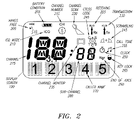
Once at least 2 available channels have been identified, the transceiver 100 assigns or designates the lowest channel number in the available channel table as the primary channel (S-520) and the second lowest channel number in the available channel table as the standby channel (S-525). For example, if the available channel table includes channel numbers 5, 8, 12 and 13, channel number 5 will be designated as the primary channel and channel number 8 will be designated as the standby channel. The primary channel number may be displayed using the channel number icon 215 or the channel number 275. The primary channel and the standby channel can be a channel or a sub-channel. The transceiver 100 continuously updates (e.g., every 10 milliseconds) the available channel table.
Once the primary and standby channels have been designated, the user of any of the operational transceivers may initiate a call to another transceiver or group of transceivers. The transceiver that initiates the call is generally referred to as the initiator transceiver 100 and the transceiver(s) that receives the call is generally referred to as the recipient transceiver 1100. Initially, the user operating in the ISeekU mode may input using the keypad 115 or select from a menu using the up and down buttons 150, 155, the recipient identification code (or recipient identification name) of the recipient transceiver(s) to contact (S-530). For example, the user of the transceiver 100 may input 12345 and 67890 as the two recipient identification codes of the two recipient transceivers to contact. The two recipient identification codes are stored in the memory module of the initiator transceiver 100 (S-535). All other transceivers that do not have these recipient identification codes are prevented from participating in or listening to the communication. Once the recipient identification code(s) has been input or selected, the user of the initiator transceiver 100 may press the PTT button 400 to initiate communication with the recipient transceivers 1100, 1200. Specifically, the initiator transceiver 100 sends call initiate information 700 (see FIG. 7 ), which includes the recipient identification code(s), to an area defined by, for example, a 5 kilometer radius.
If the recipient identification code is substantially identical to or matches the identification code of any transceiver in the area around the initiator transceiver 100 (S-540), then the transceiver(s) is designated as the recipient transceiver(s) and operates as a recipient transceiver(s) (S-545) until the recipient operations have terminated (S-550). If the transceiver desires to operate as the initiator transceiver (S-555), then the transceiver is designated as the initiator transceiver 100 and operates as an initiator transceiver (S-560) until the initiator operations have terminated (S-565).
Referring to FIG. 6 , the initiator transceiver 100 may receive the acknowledgement information 900 from multiple (e.g., 4) recipient transceivers 1100, 1200, 1300, 1400 (S-630). In one embodiment, the recipient identification code (or recipient identification name) is displayed on the caller number display area 270 upon proper receipt of the acknowledgement information 900. In order to attenuate interferences caused by multiple recipient transceivers 1100 transmitting the acknowledgement information 900 at the same time, the recipient transceivers 1100 with the higher identification codes may execute random or pseudo-random delays of varying times before transmitting the acknowledgment information 900 to the initiator transceiver 100. For example, in one embodiment, the delay may be equal to 5 times its identification code.
The initiator transceiver 100 may have a time out function (e.g., timer=T seconds, e.g., 5 seconds) in case no recipient transceivers 1100 respond to the call initiate information 700 (S-635). After receipt of the acknowledgement information 900 from at least one recipient transceiver 1100, the initiator transceiver 100 determines whether the number of acknowledgements received from the recipient transceivers 1100 is equal to the number of recipient transceivers that were sent the call initiate information 700 (S-640). If the numbers are not equal, the initiator transceiver 100 may return to S-625 to resend the call initiate information 700 to the recipient transmitters 1100 in the area. If one or more of the recipient transceivers 1100 have sent the acknowledgement information 900 to the initiator transceiver 100, the users can proceed to voice communication over the primary channel by pressing the PTT button 400 and speaking into the microphone 125 (S-645). The initiator transceiver 100 may transmit voice data to and receive voice data from one or more recipient transceivers 1100. The initiator transceiver 100 is directly connected via a direct wireless connection at a specific frequency to one or more recipient transceivers 1100. Hence, no intermediate network such as a public switched telephone network is required to connect the initiator transceiver 100 to one or more recipient transceivers 1100. Furthermore, no local or long distance telephone charges apply for the direct connection.
During voice communications, the initiator transceiver 100 scrambles (encrypts or encodes) the voice data and the recipient transceiver 1100 descramble (decrypts or decodes) the voice data and vice versa. The scrambling and descrambling can be performed using conventional scrambling and descrambling techniques. This prevents other unauthorized transceivers from listening to the voice conversations. The scrambling icon 245 may be illuminated when the scrambling or descrambling is being performed. If the PTT button 400 is not pressed or no voice data is received for a certain time period (e.g., 5 minutes), then the initiator transceiver 100 terminates the direct connections with the specific recipient transceivers 1100 (S-650). For example, if one recipient transceiver 1400 does not communicate with the initiator transceiver 100 for a period of, for example 5 minutes, the initiator transceiver 100 may terminate its connection with that particular recipient transceiver 1400 or all the recipient transceivers.
Referring to FIG. 8 , once the initiator transceiver 100 receives the acknowledgement information 900, the user of the recipient transceiver 1100 can proceed to voice communication over the primary channel by pressing the PTT button 400 and speaking into the microphone 125 (S-810). The recipient transceiver can scramble the voice data and the initiator transceiver can descramble the voice data. This prevents other unauthorized transceivers from listening to the voice conversations. If the PTT button 400 is not pressed or no voice data is received for a certain time period (e.g., 5 minutes), then the recipient transceiver 1100 may terminate the direct connection with the initiator transceiver 100 (S-815).
During voice communication between the initiator transceiver 100 and the recipient transceivers 1100, the primary channel may experience interference. Once interference is detected, the initiator transceiver 100 retrieves the standby channel number from its own available channel table, instructs the recipient transceiver 1100 via the primary channel to switch to the standby channel and switches to the standby channel. Now, the standby channel is designated as the primary channel and the initiator transceiver 100 automatically updates its available channel table (S-515) and designates the next higher channel as the standby channel. In one embodiment, the initiator transceiver 100 and the recipient transceivers 1100 are permitted to receive and transmit voice data as long as their PTT button 400 is depressed once every, for example 5 minutes, or voice data is received or transmitted at least once every, for example 5 minutes.
Although an exemplary embodiment of the invention has been shown and described, many other changes, combinations, omissions, modifications and substitutions, in addition to those set forth in the above paragraphs, may be made by one having skill in the art without necessarily departing from the spirit and scope of this invention. Accordingly, the invention is not intended to be limited by the preferred embodiments, but is to be defined by reference to the appended claims.
Claims (24)
1. A half-duplex communication device identified by an initiator identification code comprising:
a control device to
receive a first identification code and a second identification code stored in a memory,
transmit the initiator identification code, the first identification code and the second identification code directly and without using an intermediate network to a plurality of transceivers, each transceiver identified by a unique transceiver identification code,
receive first acknowledgment information from a first transceiver of the plurality of transceivers in response to the first transceiver determining that the first identification code matches the first transceiver's unique transceiver identification code, and
receive second acknowledgment information form a second transceiver of the plurality of transceivers in response to the second transceiver determining that the second identification code matches the second transceiver's unique transceiver identification code,
wherein the first acknowledgment information includes the first identification code and the second acknowledgment information includes the second identification code.
2. The communication device as defined in claim 1 wherein the control device has a direct wireless link to the first transceiver without the use of a telephone network.
3. The communication device as defined in claim 1 wherein the acknowledgement information includes the transceiver identification code.
4. The communication device as defined in claim 1 wherein the control device automatically scans a plurality of channels for an available channel.
5. The communication device as defined in claim 1 wherein the control device receives voice data, scrambles the voice data, and transmits the scrambled voice data to the first transceiver.
6. The communication device as defined in claim 5 wherein the transceiver descrambles the voice data.
7. The communication device as defined in claim 1 wherein the control device scans a plurality of channels for a signal or interference and designates an available channel as a primary channel and another available channel as a standby channel.
8. The communication device as defined in claim 7 wherein the control device creates an available channel table that includes a plurality of channel numbers representing the plurality of channels that did not have the signal or interference.
9. The communication device as defined in claim 1 wherein the initiator identification code is selected from a group consisting of a name or a number.
10. The communication device as defined in claim 1 wherein the transceiver identification code is selected from a group consisting of a name or a number.
11. A communication device identified by an initiator identification code comprising:
a processor to
receive a first identification code corresponding to a first transceiver and a second identification code corresponding to a second transceiver,
automatically scan a plurality of channels for the presence of any communication or any interference to thereby identify available channels,
create an available channel table,
select, from the available channel table, an available primary channel and an available secondary channel not used for telephone communication,
transmit via at least one of the available primary channel or the available secondary channel the initiator identification code, the first identification code and the second identification code to a plurality of transceivers including the first transceiver and the second transceiver, each transceiver having a unique transceiver identification code, and
receive, from the first transceiver, a first acknowledgement information via at least one of the available primary channel or the available secondary channel in response to the first transceiver determining the first identification code matches its unique transceiver identification code, and
receive, from the second transceiver, a second acknowledgement information via at least one of the available primary channel or the available secondary channel in response to the second transceiver determining the second identification code matches its unique transceiver identification code,
wherein the first acknowledgement information includes the first identification code and the second acknowledgement information includes the second identification code.
12. The communication device as defined in claim 11 wherein the processor receives via the available secondary channel the transceiver identification code.
13. The communication device as defined in claim 11 wherein the processor has a direct wireless link to the at least one transceiver without the use of a telephone network.
14. The communication device as defined in claim 11 wherein the initiator identification code is selected from a group consisting of a name or a number.
15. The communication device as defined in claim 11 wherein the transceiver identification code is selected from a group consisting of a name or a number.
16. A system to provide half-duplex communication comprising:
an initiator transceiver having an initiator identification code and configured to receive an a first transceiver identification code and a second transceiver identification code stored in a memory, automatically scan a plurality of channels for an available primary channel and an available secondary channel and transmit, using the available primary channel or the available secondary channel, the initiator identification code, the first transceiver identification code and the second transceiver identification code;
a first recipient transceiver having a first recipient identification code and configured to receive the initiator identification code, the first transceiver identification code and the second transceiver identification code and automatically transmit, using one of the available primary or the secondary channels, the recipient identification code to the initiator transceiver when the first transceiver identification code matches the recipient identification code; and
a second recipient transceiver having a second recipient identification code and configured to receive the initiator identification code, the first transceiver identification code and the second transceiver identification code and automatically transmit, using one of the available primary or the secondary channels, the second recipient identification code to the initiator transceiver when the second transceiver identification code matches the second recipient identification code.
17. The system as defined in claim 16 wherein the initiator transceiver has a direct wireless link to the recipient transceiver without the use of a telephone network.
18. The system as defined in claim 16 wherein the initiator transceiver transmits the initiator identification code and the recipient identification code directly to the first recipient transceiver without the use of an intermediate network.
19. The system as defined in claim 16 wherein the initiator transceiver and the first recipient transceiver operate using half-duplex communication.
20. The system as defined in claim 16 wherein the initiator transceiver and the first recipient transceiver include a scrambler for encoding voice data and a descrambler for decoding voice data.
21. The system as defined in claim 16 wherein the initiator transceiver automatically scans the plurality of channels for a signal or interference and designates the available channel as a primary channel and another available channel as a standby channel.
22. The system as defined in claim 21 wherein the initiator transceiver creates an available channel table that includes a plurality of channel numbers representing the plurality of channels that did not have the signal or interference.
23. The system as defined in claim 16 wherein the initiator identification code is selected from a group consisting of a name or a number.
24. The system as defined in claim 16 wherein the first transceiver identification code is selected from a group consisting of a name or a number.
Priority Applications (2)
| Application Number | Priority Date | Filing Date | Title |
|---|---|---|---|
| US10/757,019 US7280807B2 (en) | 2004-01-14 | 2004-01-14 | Initiator device capable of two-way half-duplex communication with multiple recipient devices |
| PCT/US2004/043196 WO2005069792A2 (en) | 2004-01-14 | 2004-12-21 | Initiator device for two-way half-duplex communication |
Applications Claiming Priority (1)
| Application Number | Priority Date | Filing Date | Title |
|---|---|---|---|
| US10/757,019 US7280807B2 (en) | 2004-01-14 | 2004-01-14 | Initiator device capable of two-way half-duplex communication with multiple recipient devices |
Publications (2)
| Publication Number | Publication Date |
|---|---|
| US20050153666A1 US20050153666A1 (en) | 2005-07-14 |
| US7280807B2 true US7280807B2 (en) | 2007-10-09 |
Family
ID=34739957
Family Applications (1)
| Application Number | Title | Priority Date | Filing Date |
|---|---|---|---|
| US10/757,019 Expired - Fee Related US7280807B2 (en) | 2004-01-14 | 2004-01-14 | Initiator device capable of two-way half-duplex communication with multiple recipient devices |
Country Status (2)
| Country | Link |
|---|---|
| US (1) | US7280807B2 (en) |
| WO (1) | WO2005069792A2 (en) |
Cited By (5)
| Publication number | Priority date | Publication date | Assignee | Title |
|---|---|---|---|---|
| US20060209730A1 (en) * | 2005-03-19 | 2006-09-21 | Richard Bautista | Bi-directional audio bridge |
| US20070167141A1 (en) * | 2006-01-17 | 2007-07-19 | Takahiko Akiyama | Radio communication system |
| US20080013600A1 (en) * | 2006-07-14 | 2008-01-17 | Motorola, Inc. | Method and system for transmit frequency hopping |
| US20110111791A1 (en) * | 2009-11-09 | 2011-05-12 | Harris Corporation | Remote control of mobile radio system through portable radio system |
| US8503934B2 (en) | 2010-07-22 | 2013-08-06 | Harris Corporation | Multi-mode communications system |
Families Citing this family (13)
| Publication number | Priority date | Publication date | Assignee | Title |
|---|---|---|---|---|
| US20060251107A1 (en) * | 2005-04-21 | 2006-11-09 | Geren Bruce E | Method and system for collision avoidance in wireless communications |
| US20090011719A1 (en) * | 2007-07-02 | 2009-01-08 | Dmitry Khabashesku | Radio Communication System and Method |
| US8045499B2 (en) * | 2008-10-03 | 2011-10-25 | Motorola Solutions, Inc. | Method of communicating which channel is to be monitored by subscriber units that are idle in a communication system |
| US8358968B2 (en) * | 2008-10-03 | 2013-01-22 | Motorola Solutions, Inc. | Method for selecting a channel to be monitored by subscriber units that are idle in a communication system |
| US8139597B2 (en) * | 2008-10-03 | 2012-03-20 | Motorola Solutions, Inc. | Method for trunking radio frequency resources |
| US8279991B2 (en) * | 2008-10-03 | 2012-10-02 | Motorola Solutions, Inc. | Method of efficiently synchronizing to a desired timeslot in a time division multiple access communication system |
| US8184654B2 (en) * | 2008-10-03 | 2012-05-22 | Motorola Solutions, Inc. | Method for ending a call session in a communication system |
| JP5581597B2 (en) * | 2009-02-05 | 2014-09-03 | 独立行政法人情報通信研究機構 | Portable communication relay device |
| US20120254924A1 (en) * | 2009-10-29 | 2012-10-04 | Amimon Ltd | method circuit and system for detecting a connection request while maintaining a low power mode |
| US8503409B2 (en) | 2010-04-15 | 2013-08-06 | Motorola Solutions, Inc. | Method for direct mode channel access |
| US8599826B2 (en) | 2010-04-15 | 2013-12-03 | Motorola Solutions, Inc. | Method for synchronizing direct mode time division multiple access (TDMA) transmissions |
| US8462766B2 (en) | 2011-03-07 | 2013-06-11 | Motorola Solutions, Inc. | Methods and apparatus for diffusing channel timing among subscriber units in TDMA direct mode |
| EP2568763B1 (en) * | 2011-09-07 | 2016-07-20 | National Chung-Shan Institute of Science and Technology | Full-duplex wireless voice broadcasting system with channel-changing and interference-resistance |
Citations (34)
| Publication number | Priority date | Publication date | Assignee | Title |
|---|---|---|---|---|
| US3939418A (en) | 1974-10-07 | 1976-02-17 | Marvin Glass & Associates | Walkie-talkie device |
| US4903298A (en) * | 1988-07-27 | 1990-02-20 | Sunstrand Data Control, Inc. | System for providing encryption and decryption of voice and data transmissions to and from an aircraft |
| US5276916A (en) | 1991-10-08 | 1994-01-04 | Motorola, Inc. | Communication device having a speaker and microphone |
| US5309502A (en) | 1990-08-07 | 1994-05-03 | Matsushita Electric Industrial Co., Ltd. | Radio telephone having a cordless or cellular only mode and a cordless/cellular mode |
| US5533099A (en) | 1994-03-22 | 1996-07-02 | Nokia Mobile Phones Ltd. | Multi-mode radio telephone |
| US5590399A (en) | 1995-02-23 | 1996-12-31 | Nextel Communications | Up-link channel assignment scheme for cellular mobile communications systems employing multi-beam antennas with beam selection |
| US5852784A (en) | 1996-04-08 | 1998-12-22 | Matsushita Electric Industrial Co., Ltd. | Multiband mobile unit communication apparatus |
| US5912931A (en) | 1996-08-01 | 1999-06-15 | Nextel Communications | Method for multicarrier signal detection and parameter estimation in mobile radio communication channels |
| US5953661A (en) | 1997-05-16 | 1999-09-14 | Nextel Communications | Method of maximizing spectral efficiency in a cellular communications system |
| US5987334A (en) | 1996-02-27 | 1999-11-16 | Nec Corporation | Multi-modal handy phone |
| US5999823A (en) | 1996-07-18 | 1999-12-07 | Matsushita Electric Industrial Co., Ltd. | Cellular cordless telephone |
| US6009323A (en) | 1997-05-01 | 1999-12-28 | Motorola, Inc. | Method of placing a call in a two-way radio communication system |
| US6044267A (en) | 1997-03-24 | 2000-03-28 | At&T Corporation | Method for network operability of a multi-function cordless/cellular telephone |
| US6091329A (en) * | 1995-11-13 | 2000-07-18 | Evenflo Company, Inc. | Monitor/hands-free intercom |
| US6144848A (en) * | 1995-06-07 | 2000-11-07 | Weiss Jensen Ellis & Howard | Handheld remote computer control and methods for secured interactive real-time telecommunications |
| US6163680A (en) * | 1998-06-17 | 2000-12-19 | Motorola, Inc. | Two way radio communication system and method for establishing communication |
| US6215474B1 (en) | 1998-07-27 | 2001-04-10 | Motorola, Inc. | Communication device with mode change softkeys |
| US6219545B1 (en) | 1996-04-04 | 2001-04-17 | U.S. Philips Corporation | Telecommunications system and a cordless access subsystem |
| US6243573B1 (en) * | 1998-05-15 | 2001-06-05 | Northrop Grumman Corporation | Personal communications system |
| US6256491B1 (en) * | 1997-12-31 | 2001-07-03 | Transcript International, Inc. | Voice security between a composite channel telephone communications link and a telephone |
| US6272331B1 (en) | 1998-02-23 | 2001-08-07 | Cobra Electronics Corporation | 2-way radio with silent annunciation |
| US20010029191A1 (en) | 2000-04-05 | 2001-10-11 | Michael Wilhelm | Radio communications system and components for a method of radio tansmission by various radio transmissin modes |
| US6321095B1 (en) * | 1999-03-26 | 2001-11-20 | Sherman Gavette | Wireless communications approach |
| US20020006806A1 (en) | 2000-06-22 | 2002-01-17 | Kimmo Kinnunen | User interface for radio telephone |
| US6351653B1 (en) | 2000-06-15 | 2002-02-26 | Motorola, Inc. | Cellular telephone with simultaneous radio and cellular communications |
| US6374091B1 (en) | 1998-06-15 | 2002-04-16 | Motorola, Inc. | Dual mode communication device |
| US6415158B1 (en) | 1999-02-01 | 2002-07-02 | Lucent Technologies Inc. | Dual mode mobile phone operating as a two-way radio |
| US20020119792A1 (en) | 2001-02-28 | 2002-08-29 | Motorola, Inc | Method and apparatus for providing dispatch services in a cordless telephone communication system |
| US20020132635A1 (en) | 2001-03-16 | 2002-09-19 | Girard Joann K. | Method of automatically selecting a communication mode in a mobile station having at least two communication modes |
| US6463304B2 (en) * | 1999-03-04 | 2002-10-08 | Openwave Systems Inc. | Application launcher for a two-way mobile communications device |
| US20020198020A1 (en) | 2001-06-26 | 2002-12-26 | Mooney Philip D. | Automatic handoff for wireless piconet multimode cell phone |
| US20040116073A1 (en) * | 1998-06-15 | 2004-06-17 | Sbc, Inc. | Enhanced wireless handset, including direct handset-to-handset communication mode |
| US20040209569A1 (en) * | 2003-04-16 | 2004-10-21 | Tomi Heinonen | Short-range radio terminal adapted for data streaming and real time services |
| US7076209B2 (en) * | 2002-03-04 | 2006-07-11 | Kabushiki Kaisha Toshiba | Short range radio communication system with using improved authentication scheme |
Family Cites Families (1)
| Publication number | Priority date | Publication date | Assignee | Title |
|---|---|---|---|---|
| US6366782B1 (en) * | 1999-10-08 | 2002-04-02 | Motorola, Inc. | Method and apparatus for allowing a user of a display-based terminal to communicate with communication units in a communication system |
-
2004
- 2004-01-14 US US10/757,019 patent/US7280807B2/en not_active Expired - Fee Related
- 2004-12-21 WO PCT/US2004/043196 patent/WO2005069792A2/en active Application Filing
Patent Citations (34)
| Publication number | Priority date | Publication date | Assignee | Title |
|---|---|---|---|---|
| US3939418A (en) | 1974-10-07 | 1976-02-17 | Marvin Glass & Associates | Walkie-talkie device |
| US4903298A (en) * | 1988-07-27 | 1990-02-20 | Sunstrand Data Control, Inc. | System for providing encryption and decryption of voice and data transmissions to and from an aircraft |
| US5309502A (en) | 1990-08-07 | 1994-05-03 | Matsushita Electric Industrial Co., Ltd. | Radio telephone having a cordless or cellular only mode and a cordless/cellular mode |
| US5276916A (en) | 1991-10-08 | 1994-01-04 | Motorola, Inc. | Communication device having a speaker and microphone |
| US5533099A (en) | 1994-03-22 | 1996-07-02 | Nokia Mobile Phones Ltd. | Multi-mode radio telephone |
| US5590399A (en) | 1995-02-23 | 1996-12-31 | Nextel Communications | Up-link channel assignment scheme for cellular mobile communications systems employing multi-beam antennas with beam selection |
| US6144848A (en) * | 1995-06-07 | 2000-11-07 | Weiss Jensen Ellis & Howard | Handheld remote computer control and methods for secured interactive real-time telecommunications |
| US6091329A (en) * | 1995-11-13 | 2000-07-18 | Evenflo Company, Inc. | Monitor/hands-free intercom |
| US5987334A (en) | 1996-02-27 | 1999-11-16 | Nec Corporation | Multi-modal handy phone |
| US6219545B1 (en) | 1996-04-04 | 2001-04-17 | U.S. Philips Corporation | Telecommunications system and a cordless access subsystem |
| US5852784A (en) | 1996-04-08 | 1998-12-22 | Matsushita Electric Industrial Co., Ltd. | Multiband mobile unit communication apparatus |
| US5999823A (en) | 1996-07-18 | 1999-12-07 | Matsushita Electric Industrial Co., Ltd. | Cellular cordless telephone |
| US5912931A (en) | 1996-08-01 | 1999-06-15 | Nextel Communications | Method for multicarrier signal detection and parameter estimation in mobile radio communication channels |
| US6044267A (en) | 1997-03-24 | 2000-03-28 | At&T Corporation | Method for network operability of a multi-function cordless/cellular telephone |
| US6009323A (en) | 1997-05-01 | 1999-12-28 | Motorola, Inc. | Method of placing a call in a two-way radio communication system |
| US5953661A (en) | 1997-05-16 | 1999-09-14 | Nextel Communications | Method of maximizing spectral efficiency in a cellular communications system |
| US6256491B1 (en) * | 1997-12-31 | 2001-07-03 | Transcript International, Inc. | Voice security between a composite channel telephone communications link and a telephone |
| US6272331B1 (en) | 1998-02-23 | 2001-08-07 | Cobra Electronics Corporation | 2-way radio with silent annunciation |
| US6243573B1 (en) * | 1998-05-15 | 2001-06-05 | Northrop Grumman Corporation | Personal communications system |
| US6374091B1 (en) | 1998-06-15 | 2002-04-16 | Motorola, Inc. | Dual mode communication device |
| US20040116073A1 (en) * | 1998-06-15 | 2004-06-17 | Sbc, Inc. | Enhanced wireless handset, including direct handset-to-handset communication mode |
| US6163680A (en) * | 1998-06-17 | 2000-12-19 | Motorola, Inc. | Two way radio communication system and method for establishing communication |
| US6215474B1 (en) | 1998-07-27 | 2001-04-10 | Motorola, Inc. | Communication device with mode change softkeys |
| US6415158B1 (en) | 1999-02-01 | 2002-07-02 | Lucent Technologies Inc. | Dual mode mobile phone operating as a two-way radio |
| US6463304B2 (en) * | 1999-03-04 | 2002-10-08 | Openwave Systems Inc. | Application launcher for a two-way mobile communications device |
| US6321095B1 (en) * | 1999-03-26 | 2001-11-20 | Sherman Gavette | Wireless communications approach |
| US20010029191A1 (en) | 2000-04-05 | 2001-10-11 | Michael Wilhelm | Radio communications system and components for a method of radio tansmission by various radio transmissin modes |
| US6351653B1 (en) | 2000-06-15 | 2002-02-26 | Motorola, Inc. | Cellular telephone with simultaneous radio and cellular communications |
| US20020006806A1 (en) | 2000-06-22 | 2002-01-17 | Kimmo Kinnunen | User interface for radio telephone |
| US20020119792A1 (en) | 2001-02-28 | 2002-08-29 | Motorola, Inc | Method and apparatus for providing dispatch services in a cordless telephone communication system |
| US20020132635A1 (en) | 2001-03-16 | 2002-09-19 | Girard Joann K. | Method of automatically selecting a communication mode in a mobile station having at least two communication modes |
| US20020198020A1 (en) | 2001-06-26 | 2002-12-26 | Mooney Philip D. | Automatic handoff for wireless piconet multimode cell phone |
| US7076209B2 (en) * | 2002-03-04 | 2006-07-11 | Kabushiki Kaisha Toshiba | Short range radio communication system with using improved authentication scheme |
| US20040209569A1 (en) * | 2003-04-16 | 2004-10-21 | Tomi Heinonen | Short-range radio terminal adapted for data streaming and real time services |
Cited By (8)
| Publication number | Priority date | Publication date | Assignee | Title |
|---|---|---|---|---|
| US20060209730A1 (en) * | 2005-03-19 | 2006-09-21 | Richard Bautista | Bi-directional audio bridge |
| US20070167141A1 (en) * | 2006-01-17 | 2007-07-19 | Takahiko Akiyama | Radio communication system |
| US20080013600A1 (en) * | 2006-07-14 | 2008-01-17 | Motorola, Inc. | Method and system for transmit frequency hopping |
| US7606291B2 (en) * | 2006-07-14 | 2009-10-20 | Motorola, Inc. | Method and system for transmit frequency hopping |
| AU2007272728B2 (en) * | 2006-07-14 | 2011-03-10 | Motorola Solutions, Inc. | Method and system for transmit frequency hopping |
| US20110111791A1 (en) * | 2009-11-09 | 2011-05-12 | Harris Corporation | Remote control of mobile radio system through portable radio system |
| US8428573B2 (en) | 2009-11-09 | 2013-04-23 | Harris Corporation | Remote control of mobile radio system through portable radio system |
| US8503934B2 (en) | 2010-07-22 | 2013-08-06 | Harris Corporation | Multi-mode communications system |
Also Published As
| Publication number | Publication date |
|---|---|
| US20050153666A1 (en) | 2005-07-14 |
| WO2005069792A2 (en) | 2005-08-04 |
| WO2005069792A3 (en) | 2009-04-02 |
Similar Documents
| Publication | Publication Date | Title |
|---|---|---|
| US7280807B2 (en) | Initiator device capable of two-way half-duplex communication with multiple recipient devices | |
| JP3093273B2 (en) | Call routing system for wireless data devices | |
| US4972479A (en) | Method and apparatus for providing privacy/security in a communication system | |
| KR100665433B1 (en) | Wireless push-to-talk internet broadcast | |
| US4430755A (en) | Portable radio telephone | |
| US5371783A (en) | Method for continually monitoring the status of a radio frequency link | |
| JP5521004B2 (en) | Cellular telephone for simultaneous wireless communication and cellular communication | |
| US5805992A (en) | Method for validating a communication link | |
| US6507734B1 (en) | Method and system which uses sound wave based communication to generate a secure wireless link between a handset and base station | |
| JPS58502128A (en) | Method and apparatus for transmitting telephone calls to a portable radiotelephone | |
| US6473613B2 (en) | Method and system for generating a secure wireless link between a handset and base station | |
| US20070291822A1 (en) | Radio communication system | |
| US6477384B2 (en) | Checking the presence of mobile stations communicating on a direct mode channel | |
| US7292845B2 (en) | Cell phone having local wireless conference call capabilities | |
| CA1175933A (en) | Subscriber telephone station | |
| US5168522A (en) | Wireless telephone with frequency inversion scrambling | |
| US6205338B1 (en) | Intercommunication method between portable units in TDMA cordless telephone system | |
| WO1995031080A1 (en) | A method for establishing a communication link | |
| KR20100083530A (en) | Mobile phone with family radio service and method for operating the same | |
| US7376416B2 (en) | Subscriber radiotelephone terminal unit and terminals for such units | |
| JPH0420537B2 (en) | ||
| EP0897237A2 (en) | TDMA communication device and method | |
| US7808945B1 (en) | Apparatus and methods for selectively communicating voice communications via a fee-based network and a nonfee-based spectrum | |
| EP1145452A1 (en) | Full-duplex radio-communication device with half-duplex functionality | |
| JPH0613973A (en) | Communication system, base station and hand set |
Legal Events
| Date | Code | Title | Description |
|---|---|---|---|
| FPAY | Fee payment |
Year of fee payment: 4 |
|
| REMI | Maintenance fee reminder mailed | ||
| LAPS | Lapse for failure to pay maintenance fees | ||
| STCH | Information on status: patent discontinuation |
Free format text: PATENT EXPIRED DUE TO NONPAYMENT OF MAINTENANCE FEES UNDER 37 CFR 1.362 |
|
| FP | Lapsed due to failure to pay maintenance fee |
Effective date: 20151009 |