US7277917B2 - Asynchronous messaging using a dynamic routing network - Google Patents
Asynchronous messaging using a dynamic routing network Download PDFInfo
- Publication number
- US7277917B2 US7277917B2 US11/347,802 US34780206A US7277917B2 US 7277917 B2 US7277917 B2 US 7277917B2 US 34780206 A US34780206 A US 34780206A US 7277917 B2 US7277917 B2 US 7277917B2
- Authority
- US
- United States
- Prior art keywords
- client device
- update
- live
- live object
- routing network
- Prior art date
- Legal status (The legal status is an assumption and is not a legal conclusion. Google has not performed a legal analysis and makes no representation as to the accuracy of the status listed.)
- Expired - Lifetime
Links
- 230000004913 activation Effects 0.000 claims description 52
- 238000000034 method Methods 0.000 claims description 33
- 230000008859 change Effects 0.000 claims description 20
- 230000008569 process Effects 0.000 claims description 10
- 230000000007 visual effect Effects 0.000 claims description 5
- 238000004590 computer program Methods 0.000 claims 1
- 238000004891 communication Methods 0.000 description 13
- 238000013515 script Methods 0.000 description 11
- 238000010586 diagram Methods 0.000 description 10
- 230000000694 effects Effects 0.000 description 8
- 230000000875 corresponding effect Effects 0.000 description 7
- 230000006870 function Effects 0.000 description 6
- 230000003993 interaction Effects 0.000 description 6
- 238000013507 mapping Methods 0.000 description 6
- 230000004044 response Effects 0.000 description 5
- 230000008901 benefit Effects 0.000 description 4
- 230000001413 cellular effect Effects 0.000 description 4
- 238000007726 management method Methods 0.000 description 4
- 230000009471 action Effects 0.000 description 3
- 239000000284 extract Substances 0.000 description 3
- 238000012545 processing Methods 0.000 description 3
- 238000013459 approach Methods 0.000 description 2
- 230000003247 decreasing effect Effects 0.000 description 2
- 230000002085 persistent effect Effects 0.000 description 2
- 230000003213 activating effect Effects 0.000 description 1
- 230000005540 biological transmission Effects 0.000 description 1
- 230000000903 blocking effect Effects 0.000 description 1
- 238000004422 calculation algorithm Methods 0.000 description 1
- 230000001276 controlling effect Effects 0.000 description 1
- 238000013461 design Methods 0.000 description 1
- 238000011161 development Methods 0.000 description 1
- 238000013073 enabling process Methods 0.000 description 1
- 238000005516 engineering process Methods 0.000 description 1
- 238000010295 mobile communication Methods 0.000 description 1
- 238000012544 monitoring process Methods 0.000 description 1
- 238000005457 optimization Methods 0.000 description 1
- 238000001228 spectrum Methods 0.000 description 1
- 238000012546 transfer Methods 0.000 description 1
- 230000001131 transforming effect Effects 0.000 description 1
Images


Classifications
-
- H—ELECTRICITY
- H04—ELECTRIC COMMUNICATION TECHNIQUE
- H04L—TRANSMISSION OF DIGITAL INFORMATION, e.g. TELEGRAPHIC COMMUNICATION
- H04L67/00—Network arrangements or protocols for supporting network services or applications
- H04L67/50—Network services
- H04L67/60—Scheduling or organising the servicing of application requests, e.g. requests for application data transmissions using the analysis and optimisation of the required network resources
- H04L67/63—Routing a service request depending on the request content or context
Definitions
- This invention pertains in general to transferring information through digital networks and in particular to transferring information for remotely updating content at client devices through the digital networks.
- the Internet is a digital network of computers.
- An individual computer on the Internet is typically identified by an internet protocol (IP) address.
- IP internet protocol
- a computer on the Internet sends a packet of information to another computer by routing the packet to a logical port at the destination computer's IP address.
- the destination computer interprets the packet according to one of several possible protocols determined by the port to which the packet was sent.
- the World Wide Web (the “Web”) is a collection of technology and content available on the Internet that allows the content to be routed from server computers to particular destination computers.
- the Web includes a large number of web pages residing on many different servers. Web pages contain one or more files, or references to one or more files, specifying instructions for presenting the web page and content, such as text, images, applets, video, and/or audio.
- HTML Hypertext Markup Language
- HTML uses a system of “tags” to specify how content should be displayed.
- Recent advances in HTML introduce “style sheets” which help separate content information from display information.
- HTML has also been modified and extended to provide new capabilities.
- Extensible Markup Language (XML) adds semantic content to web pages.
- Dynamic HTML (DHTML) adds some dynamic content to web pages.
- a web page may also include one or more programs for controlling how the web page is displayed.
- JAVA® applets and JAVASCRIPT® scripts may be used to control the display of a web page.
- DHTML uses scripts to control the dynamic content.
- a web page designer can use applets and scripts to produce animation effects or modify the display based on user interaction. For example, the designer can write a script that changes the color of a piece of text when a user clicks on a button.
- Client devices that display/execute web pages are often called “client devices” or simply “clients.”
- Client devices include personal computers, web-enabled set-top boxes and televisions, cellular telephones, personal digital assistants and other handheld devices, and special-purpose web-browsing appliances.
- Client devices typically employ a program called a “web browser” for interpreting the HTML or other display instructions in the web page and displaying the content accordingly.
- Most web browsers include special functionality, such as a Java Virtual Machine, for executing JAVA® applets and/or other applets or scripts embedded in the web pages.
- a client device specifies a web page or other document on the web using a Uniform Resource Locator (URL).
- a URL has the form “service://server/path/file.”
- service refers to the protocol to be used, such as the file transfer protocol (FTP) or the hypertext transport protocol (HTTP).
- FTP file transfer protocol
- HTTP hypertext transport protocol
- Server is the IP address of the server containing the page, and “path/file” specifies the particular web page on the server.
- the Web suffers from a substantial limitation with respect to dynamically updating content in a web page at a client device.
- the Web's only mode of operation is for a client device to first request a page from a server and then for the server to send the requested page to the client device.
- the server delivers the page to the client, it typically terminates its connection to the client, and does not retain any information about the client or the page that was sent. For this reason, servers are typically “stateless.”
- client devices drive and control the flow of information around the Web. While client-side control is appropriate in some situations, it does not permit efficient updating of data at the client devices.
- a web page contains information that may change, such as the score of a baseball game or a stock quote
- the server has no way to inform the client devices that are viewing the page of the change. Instead, the client devices must ask the server for the updated information. However, the client devices do not know when the information on the web page has changed, and thus do not know to ask for the update.
- the performance of automatic refreshing can be improved somewhat by putting information that may change in a separate frame from information that is less likely to change, and only refreshing the separate frame.
- a few web designers even write custom JAVA applets to limit refreshing to individual components on a page, such as the score of a soccer game.
- a willingness to go to such effort illustrates the serious drain of resources caused by frequent refreshing.
- Custom applets require a large separate development effort for each item on each page that might need to be updated. More importantly, most custom applets still update content based upon client-driven requests, although it is possible to design an applet that accepts “pushed” messages. This solution is not scalable to provide updated information for large numbers of client devices and for large numbers of web pages.
- a dynamic content routing network that routes messages containing data for updating properties of live objects to clients displaying web pages other representations of data containing the live objects.
- the web server that initially provides the web pages to the clients does not need to track which clients are currently displaying the live objects. Instead, the information provider or a dynamic content provider (generically referred to as an “input source”) that provided the live object simply sends an update message to the routing network.
- the routing network maintains the mappings between the live objects and the clients that are currently displaying them. This routing utilizes bandwidth efficiently because the update messages are provided to the clients only when the live objects change.
- a web server associated with an input source provides web pages to clients.
- the web pages contain live objects identified by object IDs.
- An activation module at the client examines the web page and identifies the object IDs of the live objects on the web page. Then, the activation module establishes a connection with the routing network and registers for the object IDs.
- the routing network maintains a registry indicating which clients have registered for which live objects.
- An input source provides update messages to the routing network.
- An update message preferably contains an object ID and data for updating a property of the identified live object.
- the routing network determines the clients that have registered for the identified object ID, and then routes the message to those clients.
- the activation modules at the clients receive the message and update the properties of the live object as specified by the data in the message.
- FIG. 1 is a high-level block diagram illustrating an environment containing a dynamic content routing network
- FIG. 2 is an interaction diagram illustrating interactions among a server, information provider, dynamic content provider, client, and routing network to update a property of a live object on a web page;
- FIG. 3 is a high-level diagram graphically indicating the many-to-many mapping performed by the routing network
- FIG. 4 illustrates two different web pages containing sports scores
- FIG. 5 is a block diagram illustrating an input source and the tools available to it for generating the update messages
- FIG. 6 is a flow chart illustrating the steps performed by an embodiment of an activation module
- FIG. 7 is a block diagram illustrating a lower-level view of the routing network according to an embodiment of the present invention.
- FIG. 8 is a flow chart illustrating steps performed by a node in a cluster to perform object-based routing of a message received from an input source via the gateway.
- FIG. 1 is a high-level block diagram illustrating an environment 100 containing a dynamic content routing network 110 (hereafter referred to as the “routing network”).
- the environment 100 also contains a server 112 in communication with a client 114 , an information provider 108 , and a dynamic content provider 116 .
- a typical environment 100 will have hundreds of servers 112 and information providers 108 , thousands (or even millions) of clients 114 , and multiple dynamic content providers 116 , FIG. 1 illustrates only one of each of these entities in order to enhance the clarity of this description.
- the server 112 , client 114 , information provider 108 , dynamic content provider 116 , and routing network 110 are preferably in communication via conventional communications links 117 such as those comprising the Internet.
- the communications links 117 include known wired communications media, such as dedicated or shared data, cable television or telephone lines, and/or known wireless communications media, such as communications over the cellular telephone network using protocols such as the global system for mobile communications (GSM), code division multiple access (CDMA), time division multiple access (TDMA), etc.
- GSM global system for mobile communications
- CDMA code division multiple access
- TDMA time division multiple access
- the entities may each be in communication with one or more Internet Service Providers (ISPs) (not shown) that provide each entity with access to other computers on the Internet.
- ISPs Internet Service Providers
- the server 112 , client 114 , information provider 108 , dynamic content provider 116 , and routing network 110 are preferably each identified by at least one Internet Protocol (IP) address such as “66.35.209.224.”
- IP Internet Protocol
- the IP address may also have one or more domain names associated with it, such as “bangnetworks.com.”
- Alternative embodiments of the present invention may use alternative addressing schemes and/or naming conventions instead of, or in addition to, those described herein. For example, embodiments wherein one or more of the clients are cellular telephones or other portable devices may rely on different addressing schemes.
- the information provider 108 provides web pages or other representations of data to the server 112 .
- the web pages contain one or more “live objects,” which are designated to be real-time dynamically-updateable objects. Each live object is identified by an object identifier, or object ID.
- the server 112 provides the web pages 118 to multiple clients 114 .
- the clients 114 contact the routing network 110 and register for update messages for the object IDs on the web page.
- the routing network 110 preferably maintains a registry indicating which clients have registered for which object IDs.
- the information provider 108 and/or dynamic content provider 116 send update messages to the routing network 110 . These messages can be sent any time the information provider 108 or dynamic content provider 116 wants to update a property of a live object. Each update message preferably identifies a live object and contains data for updating a property of the identified live object.
- the routing network 110 accesses the registry and determines which clients have registered for the identified object. Then, the routing network 110 routes the update message to the appropriate clients. Upon receipt of an update message, the clients 114 update the specified property of the live object.
- the routing network 110 provides an efficient one-to-many mapping of objects to clients (and by inference of information, a many-to-many mapping of information providers 108 /dynamic content providers 116 to clients) through object-based routing.
- Messages provided by the information provider 108 and/or dynamic content provider 116 to the routing network 110 are not routed to the clients 114 based entirely on a specified destination; more specifically, they are not routed based on the IP address of the client, as in conventional IP routing schemes. Instead, the messages are routed based on the live objects referenced by the message.
- the mapping and object-based routing provided by the routing network 110 allow the information provider 108 and dynamic content provider 116 to update properties of live objects at a dynamically changing cross-section of clients in real-time, without requiring the information provider or dynamic content provider to track the clients or web pages being viewed by the clients.
- the clients 114 do not need to have any a priori knowledge of object IDs—they “discover” which IDs they should register when they receives the web pages 118 from the server 112 .
- Object-based routing also allows information providers 108 to dynamically update content on web pages without requiring the clients 114 to re-request the content, and without requiring the information providers 108 or servers 112 to maintain connections with the clients. In this manner, significantly more clients can receive updated content from a given information provider 108 than would be possible utilizing conventional client-side request-driven transmission control protocol/Internet Protocol (TCP/IP) connections between the clients and the server 112 .
- TCP/IP transmission control protocol/Internet Protocol
- the server 112 is preferably a conventional computer system configured to act as a web server and serves web pages 118 and other data representations to clients 114 .
- the web pages 118 provided by the server 112 are associated with one or more information providers 108 .
- An information provider 108 is an entity providing one or more web pages 118 , information contained in web pages, and/or other representations of data served by the server 112 .
- the information provider 108 preferably has a conventional computer system coupled to the Internet.
- the server 112 is directly controlled by the information provider 108 (e.g., the server is physically located at the information provider and/or is dedicated to serving only the information provider's web pages).
- the server 112 and information provider 108 can be treated as the same entity.
- the server 112 serves web pages from multiple information providers.
- the web pages 118 and other content on the server 112 are specified by uniform resource locators (URLs) having the form “service://server/path/web page.”
- URLs uniform resource locators
- web pages 118 are obtained via the hypertext transport protocol (HTTP) and thus an exemplary URL for retrieving the web page “b1.html” from the web server having the domain name “www.bangnetworks.com” is “http://www.bangnetworks.com/news/b1.html.”
- a “web page” is a block of data available from the server 112 .
- a web page is a file written in the hypertext markup language (HTML).
- the web page may also contain or refer to one or more other blocks of data, such as other files, text, images, applets, video, and/or audio.
- the web page may contain instructions for presenting the web page and its content, such as HTML tags and style sheets.
- the instructions may also be in the Extensible Markup Language (XML), which is related to HTML and adds semantic content to web pages or the Dynamic HTML (DHTML), which adds some dynamic content to web pages.
- the instructions may take the form of one or more programs such as JAVA® applets and JAVASCRIPT® and/or DHTML scripts.
- web page also refers to other representations of data served by the server 112 regardless of whether these data representations include characteristics of conventional web pages.
- data representations include, for example, application programs and data intended for the web browser 120 or other application programs residing at the clients 114 or elsewhere, such as spreadsheet or textual (e.g., word processing) data, etc.
- objects at the client can be designated as “live” by the information provider 108 .
- Properties of a live object can be dynamically updated in real-time at the client 114 by the information provider 108 or another entity acting on behalf of the information provider.
- an “object” is any datum or data at the client 114 that can be individually identified or accessed. Examples of objects include elements of web pages such as text characters and strings, images, frames, tables, audio, video, applets, scripts, HTML, XML, and other code forming the web page, variables and other information used by applets, scripts and/or code, URLs embedded in the web page, etc.
- Application and operating system constructs are also objects.
- cells of spreadsheets, text in word processor documents, and title bars and messages displayed by the operating system or applications are objects.
- multiple objects can be grouped together into a single, logical object.
- an object can be defined at any desired or useful level of granularity.
- the present invention essentially abstracts web pages and web page content, and other modules and/or functionality at the client 114 , away from the HTML code or other conventional representation. This abstraction allows the information provider 108 to update a property of an object without concern for the location, display format, or other specifics of how the data is being represented at the client 114 .
- Live objects have associated “properties” which include any modifiable data related to the object or referenced with respect to the object.
- the information provider 108 typically, but not necessarily, provides initial settings for the properties of live objects provided to the client 114 .
- the properties may or may not affect the visual representation of the object in the web page or other data representation.
- a property may affect an internal aspect of the object and, thus, a change to the property may not have any direct effect on a web page containing the object.
- the property may affect whether particular aspects of the object are modifiable, how the object responds to user input or other stimuli, etc. Additionally, a property may also have a direct effect on how the object is displayed at the client 114 .
- the property may affect the content, color, typeface, size, formatting, or other attribute of text, images, or other data displayed by the object.
- Other properties may occupy parts of the spectrum between having no effect on the visible representation of the object and having a direct effect on the visible representation of the object.
- a web page showing scores of football games may include a list of games and the current scores of the games as of the time the server 112 serves the web page. The list of games, subset of games to be displayed, and the scores of the games can be designated as live objects (or properties of a single live object) and updated as necessary or desired.
- a property can also preferably include instantiating an instance of the object or invoking functionality of the object.
- a property of a browser window object may include functionality for instantiating another browser window. This function can be invoked as a logical change to a property of the object.
- the second browser window can be referenced through the original browser window (i.e., object) or designated as a new live object.
- An information provider 108 or other entity preferably updates a live object at a client 114 via an update message.
- an update message identifies the live object and, if necessary, the property of the live object, and contains data for updating the property.
- the data may be the actual value for the property or executable code for causing the object's property to be updated.
- the data may be a simple numerical or textual value, e.g., “4,” to which the property should be set, and/or the data may be JAVASCRIPT® code or a call to a JAVASCRIPT® function at the client that effects the desired change to the property of the object.
- the update message preferably implicitly or explicitly identifies a handler at the client 114 for use in updating the live object's property.
- the client 114 utilizes a default handler when the message implicitly specifies the handler (e.g. when the message does not identify a specific handler).
- a default handler if the update message specifies the actual value for the property, a default handler generates JAVASCRIPT® code for changing the property to the specified value. If the data in the update message are JAVASCRIPT® code, the default handler does not perform any processing of the code.
- the default handlers preferably use LiveConnect to execute the JAVASCRIPT® code in a Java Virtual Machine (JVM) 122 at the client 114 and thereby update the property of the live object.
- JVM Java Virtual Machine
- the message preferably explicitly identifies a handler for performing the update.
- the message may explicitly specify a function to call on the data or the message may explicitly identify the environment in which the data should be executed.
- the data in the update message may include code for execution by a software “plug-in” such as MACROMEDIA FLASH® and the message may explicitly identify FLASH as the handler.
- the information provider 108 preferably designates an object as “live” by including a unique identifier for the object, the object ID, in the web page or other data representation provided to the client 114 .
- the information provider 108 encodes the object ID in an object's corresponding HTML “ID” attribute using the following HTML expression:
- elementIdentifier is the object ID and is preferably a string.
- the string can encode any information desired by the information provider 108 or other entity establishing the object ID and in one embodiment is a simple textual and/or numeric identifier.
- the information provider 108 begins the object ID with a predefined token, such as “Bang$,” in order to distinguish live objects from other objects that happen to have defined ID attributes. For example, an object can have the object ID “Bang$elementIdentifier.”
- each information provider 108 optionally encodes a unique information provider ID in its object IDs in order to prevent naming collisions between the object IDs of different information providers.
- the information provider ID is a textual and/or numeric identifier.
- the information provider 108 may specify the information provider ID and the object ID as part of a hierarchical namespace.
- objects are named as follows: “$namespace1$[namespace2$ . . . $namespaceN]objectId,” where “$namesapce1” is the information provider ID and the “$” operates as the name separator and defines additional optional levels of a namespace hierarchy.
- One embodiment of the system 100 supports typical directory services functionality. For example, two dollar sign characters appearing together, “$$,” refers to the top level of the namespace hierarchy.
- the object ID for a live object is preferably formed from a combination of the predefined token, the information provider ID namespace, and a value assigned by the information provider 108 .
- the object ID for a live object representing the real time price of a stock having the symbol “BANG” might be: “Bang$$informationProviderID$equities$realtime$bang.”
- “Bang$” is the predefined token that signifies a live object
- “$informationProviderID” is the ID identifying the information provider
- “$equities$realtime$” defines levels of a namespace hierarchy
- “bang” identifies the specific object.
- the object ID utilizes relative names.
- an information provider 108 referring to its own object IDs is implicitly in its own namespace. Accordingly, the information provider 108 does not need to include the information Provider ID in the object IDs it utilizes internally.
- the information provider ID is not explicitly encoded into the object ID. Instead, the information provider ID is encoded elsewhere in the web page in order to provide scope to the page's object IDs.
- the object ID identifies a point (i.e., a node in a tree) in a Document Object Model (DOM) representation of a web page or other document at the client 114 .
- DOM Document Object Model
- the DOM is a platform- and language-neutral interface that represents a document as a hierarchy of objects.
- the DOM also provides an interface that allows programs and scripts to dynamically access and update properties of the objects.
- Object properties can be inherited by descendent objects.
- the client 114 preferably executes an update message in the context of the specified point in the DOM representation.
- the update may specify a change to a property of the object at the identified point.
- the update also may specify a change to a parent or descendent of the object at the identified point.
- the update is executed relative to the specified point in the DOM representation.
- points in the DOM representation specify how to update properties of live objects located at those points. Thus, the same update may be interpreted differently depending upon the identified live object's location in the DOM representation.
- An advantage of utilizing object IDs to specify objects is that the information provider 108 or other entity providing the update message can access and change properties of objects without knowing the object's actual location in the DOM representation. Indeed, the object may be in different locations in different DOM representations and/or in multiple locations in the same DOM representation. In any of these cases, the update message will change the specified properties of all of the objects having the given object ID.
- the information provider 108 and/or the dynamic content provider 116 provides update messages to the routing network 110 .
- the dynamic content provider 116 is preferably a conventional computer system operated by an entity that provides real-time information, such as stock prices and/or sports scores.
- the information provider 108 receives updated properties for the live objects from the dynamic content provider 116 or another source (or generates the updated properties internally). Then, the information provider 108 sends an update message specifying the object ID and the change to the object property to the routing network 110 .
- the dynamic content provider 116 may be absent from the environment 100 .
- the dynamic content provider 116 provides the object IDs for live objects to one or more information providers 108 and the information providers 108 distribute the live objects to the clients 114 . Then, the dynamic content provider 116 sends messages specifying the changes to the properties of the live objects to the routing network 110 . For example, the dynamic content provider 116 distributes an object ID associated with the score of a particular baseball game to the information providers 108 . Then, the dynamic content provider 116 sends a message specifying the object ID and an update to a property of the object that controls the displayed score of the particular baseball game to the routing network 110 .
- These two embodiments are not mutually exclusive and, therefore, some updates may be provided to the routing network 110 by the information provider 108 while others are provided by the dynamic content provider 116 .
- the client 114 is a device that retrieves web pages 118 and/or other information from the server 112 .
- the client 114 is a conventional personal computer used by a person to access information on the Internet.
- the client 114 is a different consumer electronic device having Internet connectivity, such as an Internet-enabled television, a cellular telephone, a personal digital assistant (PDA), a web browsing appliance, etc.
- the client 114 preferably, but not necessarily, has an associated display device.
- the client 114 preferably executes a web browser 120 , such as MICROSOFT INTERNET EXPLORER®, for retrieving web pages and displaying them on the display device.
- a web browser 120 such as MICROSOFT INTERNET EXPLORER®
- the web browser 120 does not necessarily share similarities with conventional web browsers.
- the web browser 120 contains a JVM 122 for executing JAVA® applets and/or scripts.
- the web browser 120 also preferably contains Dynamic HTML capabilities, such as support for JAVASCRIPT® (or another scripting language, such as VBScript) and the Document Object Model (DOM), and enables communications between JAVA® and the scripting languages.
- Dynamic HTML capabilities such as support for JAVASCRIPT® (or another scripting language, such as VBScript) and the Document Object Model (DOM), and enables communications between JAVA® and the scripting languages.
- the web browser 120 supports the LiveConnect standard for enabling communication between JAVA® applets and scripts written in the supported scripting languages.
- the web browser 120 can also be extended through software plug-ins such as MACROMEDIA FLASH®, REAL NETWORKS REALPLAYER®, and/or APPLE QUICKTIME®.
- the functionality of the JVM 122 and/or other aspects of the web browser 120 are provided by one or more other functional units within the client 114 .
- the term “module” is used herein to refer to software computer program code and/or any hardware or circuitry utilized to provide the functionality attributed to the module.
- the web browser 120 and JVM 122 are examples of modules in the client 114 .
- the client 114 does not necessarily have a display device, web browser 120 and/or other components associated with a typical consumer device.
- the client 114 may be a dedicated purpose device having certain aspects of web connectivity such as an embedded HTTP client in a web-enabled appliance or in a controller for an automobile, audio-visual equipment, or some other device.
- a web page 118 provided from the server 112 to the client 114 preferably includes instructions for enabling the live objects on the web page.
- the instructions cause the client 114 to automatically and transparently (i.e., without user interaction) contact the routing network 110 and download an activation module 124 for activating the live objects.
- the instructions comprise a URL specifying the location of the activation module 124 at the routing network 110 .
- the client 114 obtains the activation module 124 from the server 112 or another source.
- the activation module 124 preferably contains JAVA® instructions for execution by the JVM 122 .
- the module 124 may encode the instructions in the web page 118 and/or the activation module 124 using different languages and/or techniques.
- the instructions and/or activation module 124 can be embedded in the web browser 120 or operating system, either as native code or as plug-ins. In these alternative embodiments, the web browser 120 does not have to download the activation module 124 from an external source.
- the activation module 124 preferably registers object IDs from the web page 118 downloaded by the client 114 with the routing network 110 and updates the live objects in response to update messages received from the network.
- the routing network 110 records the registrations in the registry 125 .
- the client's registrations preferably remain in effect as long as the client is displaying the associated web page 118 , although other embodiments of the system 100 may use different criteria for determining when to terminate the client's registrations.
- FIG. 2 is an interaction diagram illustrating interactions among the server 112 , information provider 108 /dynamic content provider 116 (generically referred to as an “input source 210”), client 114 , and the routing network 110 to update a property of a live object.
- the client 114 sends 212 a web page request to the server 112 .
- the server 112 provides 214 to the client 114 the web page containing or otherwise identifying the one or more live objects. Instructions encoded in the web page preferably cause the client 114 to transparently request 216 the activation module 124 from the routing network 110 .
- the routing network 110 sends 218 the activation module 124 .
- the client 114 executes 220 the activation module 124 , which identifies the object IDs of the live objects at the client and registers 222 the object IDs with the routing network 110 .
- the routing network 110 updates 223 its registry to identify the object IDs for which the client 114 has registered.
- the input source 210 sends 224 an update message to the routing network 110 in order to change a property of a live object at the client 114 .
- the message from the input source 210 to the routing network 110 contains only a single object ID and an update to a property of the identified object.
- the message contains multiple object IDs and the corresponding property updates.
- the message may have an associated “Batch ID” that identifies the message as having multiple object IDs and updates.
- the information provider 108 can include a batch ID in a web page 118 in the same manner as including an object ID.
- the client 114 can preferably register for a batch ID with the routing network 110 in the same manner as an object ID.
- the batch ID can be the same as the object ID so that the client 114 registers for both batch and non-batch messages by registering one ID.
- separate procedures can be established for registering batch messages.
- the client 114 preferably processes the component messages of a batch as if each message were delivered separately.
- the routing network 110 routes 226 the message to each client 114 that has registered for the specified object ID, preferably by utilizing standard Internet communications protocols, such as IP addresses, etc.
- the activation module 124 at the client 114 processes the message and updates 228 the property of the identified live object. If live objects having the same-object ID appear in multiple locations at the client 114 (e.g., at multiple locations on a web page being displayed at the client), the activation module 124 preferably updates each of the live objects having the specified ID.
- the routing network 110 allows live objects at the client 114 to be dynamically updated. Preferably, this routing and updating happens quickly enough to be considered “real-time” for the purposes of the input source 210 .
- This update process can repeat an indefinite number of times and is fully asynchronous as to the information provider 210 and client 114 .
- the input source 210 may send regular update messages to the routing network 110 as the score of a sporting event changes or a stock price fluctuates, but may stop sending update messages once the sporting event ends or stock market closes.
- the client 114 ends the display of a web page containing the live object, or otherwise no longer desires to receive update messages, the client preferably closes 232 the connection with the routing network 110 .
- the routing network 110 updates 234 the registry 125 to remove the client's object registrations.
- the client 114 sends messages to the routing network 110 that selectively register and/or de-register the client from one or more objects yet leaves the connection open in order to receive update messages pertaining to other objects.
- FIG. 3 is a high-level diagram graphically indicating the many-to-many mapping performed by the routing network 110 .
- Multiple input sources labeled 210 A-C
- Each update message preferably specifies at least one object ID and an update to a property of the identified object.
- the routing network 110 selectively routes the update messages to the clients 114 that have registered for the given object ID from the given input source 210 .
- FIG. 3 assume for example that clients 312 A and 312 B have registered for a given object ID while the other clients have not registered for the object ID. Accordingly, the routing network 110 routes the update message to clients 312 A and 312 B, but does not route the message to clients 312 C- 312 H.
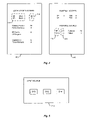
- FIG. 4 illustrates an example of the capabilities of the dynamic content routing network 110 .
- FIG. 4 illustrates two different web pages 410 , 412 containing sports scores. Although the web pages are formatted differently, each page contains the same scores for two professional football games and two professional baseball games. Web page 410 contains all four games under the heading “Local Sports Scores” while web page 412 contains the baseball games under the heading “Baseball Scores” and the football games under the heading “Football Scores.”
- a “game” object is defined having properties for the two teams involved in the game and the score associated with each team.
- the game object is placed at a selected position in the web page and the properties of the object cause the information about the game to be displayed on the page.
- “team” and “score” objects are defined, with the team object having a property defining the name of a team and the score object having a property defining a score.
- the team and score objects are placed at selected locations on the page so that the proper teams and scores are aligned when the page is rendered.
- an object is defined having properties for the name of one team and a score associated with that team.
- pairs of the objects are placed in the page in the proper alignment to indicate the games and scores.
- an object is defined having properties specifying names of two teams and a separate object is defined having properties specifying two scores.
- the two objects are placed in the page so that the names of the teams align with the associated scores.
- a names object 414 having properties set to identify the “SF 49ers” and the “STL Rams” is located directly under the “Local Sports Scores” heading.
- a scores object 416 having a property set to identify the score of the game as “42” to “7” is directly to the right of the names object 414 .
- the properties of the second names object 418 identify the same game using slightly different terminology: “SF” and “STL.” However, this names object 418 is aligned with the same scores object 416 as is utilized in web page 410 .
- the same scores object 416 is utilized in different positions in each web page 410 , 412 .
- the input source 210 simply sends an update message to the routing network 110 specifying the object ID for the scores object 416 and the update to the score property.
- the routing network 110 routes the update message to the appropriate clients 114 , and the clients update the appropriate score regardless of the particular page layout.
- the input source 210 i.e., the information provider 108 and/or dynamic content provider 116 can use a variety of tools to generate the update messages.
- FIG. 5 is a block diagram illustrating an input source 210 and the tools available to it for generating the update messages. Other tools can be utilized in addition to or instead of the ones described herein.
- the tools allow the input source 210 to access an application programming interface (API) provided by the routing network 110 for accepting messages.
- API application programming interface
- the messages sent by the input source 210 are in the same format as utilized by the activation module 124 at the client 114 .
- the messages provided to the routing network 110 are in a different format and the routing network translates the messages into the format utilized by the activation module 124 .
- the input source 210 utilizes a data pump module 510 to access the API.
- the data pump module 510 reads an extensible markup language (XML) file containing one or more object IDs and the new values for the identified objects at regular intervals and automatically generates API calls that send messages representing changes to object properties to the routing network 110 .
- the data pump module 510 is event-driven and reads the XML file in response to a change in the file or some other occurrence.
- the input source 210 utilizes a director console module 512 to access the API.
- the director console module 512 presents an administrator with a graphical interface displaying the contents of the web page 118 .
- the administrator may use the director console 512 to edit textual data, images, and/or any objects or properties of objects on the web page.
- the administrator uses a “send update” button or similar technique to cause the director console module 512 to send messages for the changed objects and properties to the routing network 110 via the API.
- the information provider 108 and dynamic content provider 116 work together as the input source 210 by using a content management system module 514 to access the API.
- the content management system module 514 resides at the information provider 108 and receives object property updates from the dynamic content provider 116 .
- the content management system module 514 preferably updates the properties of the live objects in the web page 118 stored at the server 112 and also sends messages for the changed properties to the routing network 110 . In this manner, the web page 118 at the server 112 and the web page displayed at the client 114 are updated almost simultaneously.
- the dynamic content provider 116 sends the update messages to the routing network 110 instead of to the information provider 108 .
- Embodiments of the system 100 can also utilize any combination of the content management techniques described herein.
- the tools described above can generate a message having the following code for updating the text displayed by a score object to “2”:
- LiveObject score new LiveObject(“Bang$homeScoreID”); score.setProperty(“innerText”, “2”). This code sets the innerText property of the object having object ID “Bang$homeScoreID” to “2.”
- the tools use the API to pass this message to the routing network 110 .
- FIG. 6 is a flow chart illustrating the steps performed by an embodiment of the activation module 124 .
- the activation module 124 generally performs three functions: register object IDs with the routing network 110 , handle messages received by the client 114 from the network in order to update the properties of live objects, and control communications between the client and the network.
- the activation module 124 preferably parses 610 the web page 118 received from the server 112 and identifies the object IDs of the live objects. In an alternative embodiment, the activation module 124 identifies only a subset of the object IDs, such as the IDs of only live objects that are currently being displayed by the web browser 120 . Alternatively, a list of object IDs may be pre-encoded in the web page in addition to the objects themselves, thereby enabling easy identification by the activation module 124 . In yet another embodiment, a user of the client 114 selects the object IDs to register.
- the activation module 124 preferably opens 612 a connection between the client 114 and the routing network 110 .
- the activation module 124 can open 612 this connection before or after the activation module receives and/or parses the web page 118 .
- the client 114 is located behind a firewall that puts a restriction on the types of connection requests the client can make.
- a firewall might, for example, block all non-HTTP traffic.
- the activation module 124 preferably wraps the connection request in an HTTP header in order to get the request to the routing network 110 through the firewall.
- the activation module 124 uses the connection between the client 114 and routing network 110 to register 614 the object IDs by communicating to the routing network 116 a vector (e.g., a list or array) containing the identified object IDs.
- a vector e.g., a list or array
- the activation module 124 preferably puts the vector into a string, referred to as “object data,” and then preferably creates an HTTP message to communicate the object data to the routing network 110 .
- object data a string
- POST / HTTP/1.1 ⁇ r ⁇ n Content-Length ⁇ length of object data> ⁇ r ⁇ n ⁇ r ⁇ n ⁇ object data> where ⁇ object data> is the object ID list.
- the routing network 110 receives such an HTTP request, it extracts the object data and updates the registry 125 to indicate that the client 114 has registered for the identified objects.
- the activation module 124 associated with the initial web page preferably terminates 618 the client's connection with the routing network 110 .
- this termination 618 can occur asynchronously with the other steps illustrated in FIG. 6 .
- the location of steps 616 and 618 represents only one possible place in the sequence of steps where the termination may occur.
- the activation module 124 preferably waits until it receives 618 a message from the routing network 110 specifying an object ID and an update to a property of the identified object. In one embodiment, this message is received as HTTP data. Upon receipt of the message, the activation module 124 preferably extracts 620 the object ID and update from the HTTP data. Then, the activation module 124 updates 622 the property of the identified object, or causes the object to be updated, as specified by the message.
- the sequence of receiving messages 618 , extracting data 620 , and updating objects 622 is preferably repeated until a new page is loaded 616 or the connection with the routing network 110 is otherwise terminated.
- the activation module 124 may register new object IDs with the routing network 110 without first downloading and parsing a new page. In one embodiment, if the newly-loaded page contains live objects, then the process of downloading the activation module 124 and updating the objects as described by FIG. 6 is repeated.
- the activation module 124 remains active at the client 114 and, therefore, the client does not re-download the activation module from the routing network 110 . Instead, the already-present activation module 124 performs the live-enabling process on the new page.
- FIG. 7 is a block diagram illustrating a lower-level view of the routing network 110 according to an embodiment of the present invention.
- FIG. 7 illustrates multiple input sources (labeled 710 A-D) representative of sources providing messages to the routing network 110 , such as an information provider 710 A and a dynamic content provider 710 B.
- FIG. 7 also illustrates multiple clients (labeled 712 A-F) representative of the many clients in communication with the routing network 110 at any given instant.
- the routing network 110 is preferably divided into one or more clusters 714 .
- the routing network 110 has three clusters 714 A, 714 B, 714 C, although the number of clusters can vary depending upon the processing needs of the network.
- An input-side global load balancer 716 preferably routes messages from the input sources 710 to the clusters 714 .
- a client-side global load balancer 718 preferably routes connection requests from the clients 712 to the clusters 714 .
- the load balancers 716 , 718 are designed to ensure that load is distributed among the clusters 714 according to a predetermined heuristic. For example, the load may be distributed evenly among the clusters 714 or a more powerful cluster may be distributed a majority of the load.
- one load balancer performs the functions of the input-side 716 and client-side 718 load balancers and utilizes conventional Domain Name System-(DNS-) based load balancing.
- DNS- Domain Name System-
- Each cluster 714 preferably contains an input-side cluster load balancer 720 A and a client-side cluster load balancer 722 A.
- the cluster load balancers 720 A, 722 A function similarly to the corresponding global load balancers 716 , 718 in that the input-side cluster load balancer 720 A balances and routes incoming messages among one or more gateways 724 A and the client-side cluster load balancer 722 A balances and routes incoming connection requests among one or more nodes 726 A and application servers 728 A.
- the functionality of the two client-side cluster load balancers 720 A, 722 A is provided by one component.
- This single-component load balancer initially determines whether an incoming request is from an input source 710 seeking to send a message to a gateway 724 A, a client 712 seeking a connection to a node 726 A, or a client seeking a connection to an application server 728 A. Then, the load balancer routes the messages/connection requests among the gateways 724 A, nodes 726 A, and application servers 728 A within the cluster 714 .
- the single-component load balancer provides layer seven load balancing (i.e., load balancing at the application layer).
- the load balancing for the nodes 726 A and application servers 728 A are performed by the same component since, for security reasons, most client web browsers only permit an application (e.g., the activation module 124 ) to transparently connect to the location from which the application was downloaded.
- an application e.g., the activation module 124
- routing network 110 may combine the global 716 , 718 and cluster 720 A, 722 A load balancers and/or incorporate the functionality of the load balancers into different components within or outside of the clusters 714 .
- alternative embodiments may omit one or more of these load balancers. For example, having different clusters 714 serve different customers might obviate the need for the global load balancers 716 , 718 .
- the gateways 724 A in the cluster 714 receive the messages from the input sources 710 and direct the messages to the appropriate node or nodes 726 A.
- each gateway 724 A maintains a persistent TCP connection to every node 726 in every cluster 714 and directs every message to every node. Therefore, although a gateway 724 A is located inside a cluster 714 A and receives connections via the cluster's input-side load balancer 720 A, the gateway's scope spans the entire routing network 110 . This broad scope allows messages from any input source to reach any client 712 .
- each gateway 724 maintains a persistent TCP connection to all nodes 426 in the same cluster 714 and at least one connection to at least one gateway in each of the other clusters. This embodiment reduces the number of simultaneous TCP connections maintained by each gateway 724 .
- each cluster 714 also includes a gatekeeper (not shown in FIG. 7 ) that maintains connections with the gateways 724 of other clusters. A gateway 724 forwards messages to the gatekeeper, which then distributes the messages to the gateways of other clusters 714 .
- each gateway 724 preferably maintains a queue 730 of messages that have been received but not yet processed in order to avoid losing messages. In one embodiment, the gateway 724 drops messages if the queue 730 becomes too long. In another embodiment, the gateway 724 utilizes priorities assigned to certain messages or input sources to determine which messages to drop.
- the nodes 726 preferably transmit messages received from the gateways 724 to the clients 712 that have registered in the object IDs identified by the messages. If no clients 712 have registered the object ID specified by a message, the node preferably ignores the message.
- a node 726 preferably maintains an instance of the registry 125 as a hash table 732 containing the object IDs registered by clients 712 connected to the node.
- the hash table 732 associates each object ID with a linked list containing one entry for each client 712 that has registered for that object ID. Each entry in the linked list preferably contains a pointer to a socket representing the connection to the corresponding client 712 .
- the pointer to the socket represents an address to which the node can write in order to send the message to the corresponding client.
- the node 726 adds to the hash table 732 and/or linked list every time a client 712 registers an interest in an object and deletes the corresponding entry from the hash table and/or linked list when the client disconnects from the node or otherwise indicates that it is no longer interested in a particular object.
- Alternative embodiments of the present invention utilize other data structures in addition to, or instead of, the hash table 732 and linked list, and/or may utilize different data within the data structures.
- the routing network 110 has a hierarchy of nodes within each cluster 714 . Different nodes in the hierarchy may handle messages received from certain input sources 210 , or process messages sent to different clients 712 .
- the linked lists may point to nodes lower in the hierarchy, instead of to sockets leading to the clients 712 .
- Another embodiment lacks the node hierarchy, yet assigns certain nodes to certain input sources 210 or clients 712 .
- the application server 728 within each node 714 preferably serves the activation module 124 to the clients 712 in response to client requests.
- the application server 728 serves any other modules that may be required or desired to support the environment 100 .
- a single application server 728 fulfills all of the client requests. This application server 728 may be within a certain cluster 714 or independent of the clusters. However, this single-application-server embodiment is less desirable because it lacks redundancy.
- the routing network 110 utilizes conventional single-processor computer systems executing the Linux operating system (OS).
- OS operating system
- each component of the routing network 110 is implemented by a separate, dedicated computer system in order to enable the separate optimization of the components.
- the input/output (I/O) functionality of the OS is preferably enhanced through the use of a non-blocking OS package such as NBIO available from the University of California, Berkeley, Calif.
- NBIO non-blocking OS package
- the OS is preferably configured to not allocate resources toward monitoring idle connections. Instead, the well-known /dev/poll patch is preferably applied to the OS in order to provide advanced socket polling capabilities.
- the TCP/IP stack in the OS is preferably optimized in order to quickly output messages.
- the retransmit timer in the stack is reduced from 200 ms to 50 ms. This timer determines how long the stack waits for an acknowledgement (ack) that a sent packet was received. Due to the way the Linux kernel implements the retransmit timer, the kernel will not send pending outbound packets (even if the ack has been received) until the initial retransmit timer has expired. Reducing the retransmit value minimizes the effect of this delay.
- an embodiment of the present invention increases the retransmit value for the affected TCP connection and the unacknowledged packet is retransmitted.
- the TCP/IP stack preferably utilizes Nagle's algorithm functionality to concatenate a number of small messages into a larger message, thereby reducing the number of packets sent by the routing network 110 .
- FIG. 8 is a flow chart illustrating steps performed by a node 726 in a cluster 714 to perform object-based routing of a message received from an input source via the gateway 724 .
- the node 726 receives 810 the message from an input source 710 .
- the node 726 extracts 812 the object ID from the message.
- the node 726 optionally transforms 814 the message to convert it from the format utilized by the input source 710 into the format utilized by the activation module 124 at the client 712 .
- the message format utilized by the input source 710 is identical to the message format utilized by activation module 124 . In this embodiment, therefore, the node 726 does not need to transform the message.
- the node 726 preferably transforms the message.
- the node 726 looks up 816 the hash table entry corresponding to the extracted object and information provider IDs to determine the linked list of clients 712 that have registered in the object referenced by the message. Finally, the node 726 transmits 818 the message to each of the registered clients 712 .
- the node 726 optionally transforms the message after, as opposed to before, looking up the registered clients in the hash table. Transforming the message at this latter stage enables the node 726 to transform the message according to the specific requirements of the registered clients 712 .
Abstract
Description
| LiveObject score = new LiveObject(“Bang$homeScoreID”); | ||
| score.setProperty(“innerText”, “2”). | ||
This code sets the innerText property of the object having object ID “Bang$homeScoreID” to “2.” The tools use the API to pass this message to the
| POST / HTTP/1.1\r\n | ||
| Content-Length: <length of object data> \r\n | ||
| \r\n | ||
| <object data> | ||
where <object data> is the object ID list. When the
Claims (60)
Priority Applications (1)
| Application Number | Priority Date | Filing Date | Title |
|---|---|---|---|
| US11/347,802 US7277917B2 (en) | 2000-12-18 | 2006-02-03 | Asynchronous messaging using a dynamic routing network |
Applications Claiming Priority (7)
| Application Number | Priority Date | Filing Date | Title |
|---|---|---|---|
| US25661300P | 2000-12-18 | 2000-12-18 | |
| US27684701P | 2001-03-16 | 2001-03-16 | |
| US27830301P | 2001-03-21 | 2001-03-21 | |
| US27960801P | 2001-03-28 | 2001-03-28 | |
| US28062701P | 2001-03-29 | 2001-03-29 | |
| US10/017,182 US7043525B2 (en) | 2000-12-18 | 2001-12-14 | Techniques for updating live objects at clients using a dynamic routing network |
| US11/347,802 US7277917B2 (en) | 2000-12-18 | 2006-02-03 | Asynchronous messaging using a dynamic routing network |
Related Parent Applications (1)
| Application Number | Title | Priority Date | Filing Date |
|---|---|---|---|
| US10/017,182 Continuation US7043525B2 (en) | 2000-12-18 | 2001-12-14 | Techniques for updating live objects at clients using a dynamic routing network |
Publications (2)
| Publication Number | Publication Date |
|---|---|
| US20060265488A1 US20060265488A1 (en) | 2006-11-23 |
| US7277917B2 true US7277917B2 (en) | 2007-10-02 |
Family
ID=35758653
Family Applications (2)
| Application Number | Title | Priority Date | Filing Date |
|---|---|---|---|
| US10/017,182 Expired - Lifetime US7043525B2 (en) | 2000-12-18 | 2001-12-14 | Techniques for updating live objects at clients using a dynamic routing network |
| US11/347,802 Expired - Lifetime US7277917B2 (en) | 2000-12-18 | 2006-02-03 | Asynchronous messaging using a dynamic routing network |
Family Applications Before (1)
| Application Number | Title | Priority Date | Filing Date |
|---|---|---|---|
| US10/017,182 Expired - Lifetime US7043525B2 (en) | 2000-12-18 | 2001-12-14 | Techniques for updating live objects at clients using a dynamic routing network |
Country Status (1)
| Country | Link |
|---|---|
| US (2) | US7043525B2 (en) |
Cited By (10)
| Publication number | Priority date | Publication date | Assignee | Title |
|---|---|---|---|---|
| US20050055453A1 (en) * | 2003-09-08 | 2005-03-10 | Microsoft Corporation | System and method for automatic conversion from WAP client provisioning XML represented objects to OMA DM tree structure represented objects |
| US20060075279A1 (en) * | 2004-08-17 | 2006-04-06 | Shaw Parsing, Llc | Techniques for upstream failure detection and failure recovery |
| US20060117318A1 (en) * | 2004-08-17 | 2006-06-01 | Shaw Parsing, Llc | Modular event-driven processing |
| US20060294413A1 (en) * | 2005-06-28 | 2006-12-28 | Filz Frank S | Fault tolerant rolling software upgrade in a cluster |
| US20070239822A1 (en) * | 2000-12-18 | 2007-10-11 | Timothy Tuttle | Asynchronous messaging using a node specialization architecture in the dynamic routing network |
| US7814225B2 (en) | 2000-12-18 | 2010-10-12 | Rumelhart Karl E | Techniques for delivering personalized content with a real-time routing network |
| US20100325287A1 (en) * | 2009-06-22 | 2010-12-23 | Ashok Kumar Jagadeeswaran | Systems and methods of handling non-http client or server push on http vserver |
| US20110265101A1 (en) * | 2010-04-21 | 2011-10-27 | International Business Machines Corporation | Net-timer daemon |
| RU2474071C2 (en) * | 2008-02-22 | 2013-01-27 | Квэлкомм Инкорпорейтед | Method and apparatus for asynchronous mediated communication |
| US8505024B2 (en) | 2000-12-18 | 2013-08-06 | Shaw Parsing Llc | Storing state in a dynamic content routing network |
Families Citing this family (49)
| Publication number | Priority date | Publication date | Assignee | Title |
|---|---|---|---|---|
| US7043525B2 (en) * | 2000-12-18 | 2006-05-09 | Bang Networks, Inc. | Techniques for updating live objects at clients using a dynamic routing network |
| US7085736B2 (en) * | 2001-02-27 | 2006-08-01 | Alexa Internet | Rules-based identification of items represented on web pages |
| US20040019658A1 (en) * | 2001-03-26 | 2004-01-29 | Microsoft Corporation | Metadata retrieval protocols and namespace identifiers |
| US7203756B2 (en) * | 2001-04-27 | 2007-04-10 | International Business Machines Corporation | Mechanism to cache references to Java RMI remote objects implementing the unreferenced interface |
| US7185067B1 (en) * | 2002-08-27 | 2007-02-27 | Cisco Technology, Inc. | Load balancing network access requests |
| US20080313282A1 (en) | 2002-09-10 | 2008-12-18 | Warila Bruce W | User interface, operating system and architecture |
| EP1398717A1 (en) * | 2002-09-11 | 2004-03-17 | Atsmai Technology | Data refreshing process for a computer application |
| US7386798B1 (en) | 2002-12-30 | 2008-06-10 | Aol Llc | Sharing on-line media experiences |
| US9754038B2 (en) * | 2003-02-05 | 2017-09-05 | Open Text Sa Ulc | Individually deployable managed objects and system and method for managing the same |
| US7299409B2 (en) * | 2003-03-07 | 2007-11-20 | International Business Machines Corporation | Dynamically updating rendered content |
| JP2005032230A (en) * | 2003-06-18 | 2005-02-03 | Ricoh Co Ltd | Electronic apparatus and web page generation method |
| US7480698B2 (en) * | 2003-12-18 | 2009-01-20 | International Business Machines Corporation | Updating event data on a page using code understood natively by a browser |
| US20060004804A1 (en) * | 2004-05-25 | 2006-01-05 | Cheng-Hsing Liao | System and method for timely updating specific fields of a web page |
| KR100587563B1 (en) * | 2004-07-26 | 2006-06-08 | 삼성전자주식회사 | Apparatus and method for providing context-aware service |
| WO2006027672A2 (en) * | 2004-09-10 | 2006-03-16 | Nortel Networks | System and method for adaptive frame size management in a wireless multihop network |
| US20060075336A1 (en) * | 2004-09-29 | 2006-04-06 | International Business Machines Corporation | Method, system and program product for providing content over a network |
| US7620996B2 (en) * | 2004-11-01 | 2009-11-17 | Microsoft Corporation | Dynamic summary module |
| US8090776B2 (en) * | 2004-11-01 | 2012-01-03 | Microsoft Corporation | Dynamic content change notification |
| US7756388B2 (en) * | 2005-03-21 | 2010-07-13 | Microsoft Corporation | Media item subgroup generation from a library |
| US20060218187A1 (en) * | 2005-03-25 | 2006-09-28 | Microsoft Corporation | Methods, systems, and computer-readable media for generating an ordered list of one or more media items |
| US7533091B2 (en) * | 2005-04-06 | 2009-05-12 | Microsoft Corporation | Methods, systems, and computer-readable media for generating a suggested list of media items based upon a seed |
| US7890513B2 (en) * | 2005-06-20 | 2011-02-15 | Microsoft Corporation | Providing community-based media item ratings to users |
| US7580932B2 (en) * | 2005-07-15 | 2009-08-25 | Microsoft Corporation | User interface for establishing a filtering engine |
| US7681238B2 (en) * | 2005-08-11 | 2010-03-16 | Microsoft Corporation | Remotely accessing protected files via streaming |
| US7680824B2 (en) * | 2005-08-11 | 2010-03-16 | Microsoft Corporation | Single action media playlist generation |
| US7688686B2 (en) * | 2005-10-27 | 2010-03-30 | Microsoft Corporation | Enhanced table of contents (TOC) identifiers |
| US20070100844A1 (en) * | 2005-10-28 | 2007-05-03 | International Business Machines Corporation | System and method for dynamically updating web pages using messaging-oriented middleware |
| US20070244856A1 (en) * | 2006-04-14 | 2007-10-18 | Microsoft Corporation | Media Search Scope Expansion |
| DE102006019099A1 (en) * | 2006-04-25 | 2007-10-31 | Siemens Ag | Device and method for server-side graphics creation |
| US20090276713A1 (en) * | 2008-05-01 | 2009-11-05 | Eddy Michael P | Network accessible content management methods, systems and apparatuses |
| CN102144401B (en) * | 2008-09-05 | 2014-05-14 | 汤姆逊许可证公司 | Method and system for dynamic play list modification |
| WO2010036983A1 (en) * | 2008-09-25 | 2010-04-01 | Rockliffe Systems, Inc. (Dba Mailsite) | Personal information management data synchronization |
| US20120066694A1 (en) | 2010-09-10 | 2012-03-15 | International Business Machines Corporation | Event overflow handling by coalescing and updating previously-queued event notification |
| US8694625B2 (en) * | 2010-09-10 | 2014-04-08 | International Business Machines Corporation | Selective registration for remote event notifications in processing node clusters |
| US8984119B2 (en) | 2010-11-05 | 2015-03-17 | International Business Machines Corporation | Changing an event identifier of a transient event in an event notification system |
| US8433760B2 (en) | 2010-12-03 | 2013-04-30 | International Business Machines Corporation | Inter-node communication scheme for node status sharing |
| US8667126B2 (en) | 2010-12-03 | 2014-03-04 | International Business Machines Corporation | Dynamic rate heartbeating for inter-node status updating |
| US8634328B2 (en) | 2010-12-03 | 2014-01-21 | International Business Machines Corporation | Endpoint-to-endpoint communications status monitoring |
| US8856171B2 (en) * | 2011-03-29 | 2014-10-07 | Microsoft Corporation | Locating and executing objects in a distributed network |
| US8634330B2 (en) | 2011-04-04 | 2014-01-21 | International Business Machines Corporation | Inter-cluster communications technique for event and health status communications |
| US9442687B2 (en) * | 2012-07-23 | 2016-09-13 | Korea Advanced Institute Of Science And Technology | Method and apparatus for moving web object based on intent |
| US9170716B1 (en) * | 2013-03-12 | 2015-10-27 | Ca, Inc. | System and method for a distributed graphical user interface |
| US9544373B2 (en) | 2013-12-24 | 2017-01-10 | Dropbox, Inc. | Systems and methods for maintaining local virtual states pending server-side storage across multiple devices and users and intermittent network connections |
| US9423922B2 (en) | 2013-12-24 | 2016-08-23 | Dropbox, Inc. | Systems and methods for creating shared virtual spaces |
| US10067652B2 (en) | 2013-12-24 | 2018-09-04 | Dropbox, Inc. | Providing access to a cloud based content management system on a mobile device |
| US9646103B2 (en) | 2014-07-10 | 2017-05-09 | MyMojo Corporation | Client-side template engine and method for constructing a nested DOM module for a website |
| US20160012144A1 (en) * | 2014-07-10 | 2016-01-14 | MyMojo Corporation | Javascript-based, client-side template driver system |
| US20160012023A1 (en) * | 2014-07-10 | 2016-01-14 | MyMojo Corporation | Self-Referencing of Running Script Elements in Asynchronously Loaded DOM Modules |
| US20160012147A1 (en) * | 2014-07-10 | 2016-01-14 | MyMojo Corporation | Asynchronous Initialization of Document Object Model (DOM) Modules |
Citations (11)
| Publication number | Priority date | Publication date | Assignee | Title |
|---|---|---|---|---|
| US6233600B1 (en) * | 1997-07-15 | 2001-05-15 | Eroom Technology, Inc. | Method and system for providing a networked collaborative work environment |
| US6253167B1 (en) * | 1997-05-27 | 2001-06-26 | Sony Corporation | Client apparatus, image display controlling method, shared virtual space providing apparatus and method, and program providing medium |
| US6363421B2 (en) * | 1998-05-31 | 2002-03-26 | Lucent Technologies, Inc. | Method for computer internet remote management of a telecommunication network element |
| US6418448B1 (en) * | 1999-12-06 | 2002-07-09 | Shyam Sundar Sarkar | Method and apparatus for processing markup language specifications for data and metadata used inside multiple related internet documents to navigate, query and manipulate information from a plurality of object relational databases over the web |
| US6446257B1 (en) * | 1999-02-04 | 2002-09-03 | Hewlett-Packard Company | Method and apparatus for pre-allocation of system resources to facilitate garbage collection |
| US6577328B2 (en) * | 1997-05-28 | 2003-06-10 | Sony Corporation | Program providing medium and shared virtual space providing apparatus and method |
| US6658652B1 (en) * | 2000-06-08 | 2003-12-02 | International Business Machines Corporation | Method and system for shadow heap memory leak detection and other heap analysis in an object-oriented environment during real-time trace processing |
| US6836886B2 (en) * | 2001-03-19 | 2004-12-28 | Autodesk, Inc. | Method and apparatus for delivering electronic information |
| US6871346B1 (en) * | 2000-02-11 | 2005-03-22 | Microsoft Corp. | Back-end decoupled management model and management system utilizing same |
| US7043525B2 (en) * | 2000-12-18 | 2006-05-09 | Bang Networks, Inc. | Techniques for updating live objects at clients using a dynamic routing network |
| US7051070B2 (en) * | 2000-12-18 | 2006-05-23 | Timothy Tuttle | Asynchronous messaging using a node specialization architecture in the dynamic routing network |
Family Cites Families (4)
| Publication number | Priority date | Publication date | Assignee | Title |
|---|---|---|---|---|
| US5706516A (en) * | 1995-01-23 | 1998-01-06 | International Business Machines Corporation | System for communicating messages among agent processes |
| US6029175A (en) * | 1995-10-26 | 2000-02-22 | Teknowledge Corporation | Automatic retrieval of changed files by a network software agent |
| US6324587B1 (en) * | 1997-12-23 | 2001-11-27 | Microsoft Corporation | Method, computer program product, and data structure for publishing a data object over a store and forward transport |
| US6609138B1 (en) * | 1999-03-08 | 2003-08-19 | Sun Microsystems, Inc. | E-mail list archiving and management |
-
2001
- 2001-12-14 US US10/017,182 patent/US7043525B2/en not_active Expired - Lifetime
-
2006
- 2006-02-03 US US11/347,802 patent/US7277917B2/en not_active Expired - Lifetime
Patent Citations (11)
| Publication number | Priority date | Publication date | Assignee | Title |
|---|---|---|---|---|
| US6253167B1 (en) * | 1997-05-27 | 2001-06-26 | Sony Corporation | Client apparatus, image display controlling method, shared virtual space providing apparatus and method, and program providing medium |
| US6577328B2 (en) * | 1997-05-28 | 2003-06-10 | Sony Corporation | Program providing medium and shared virtual space providing apparatus and method |
| US6233600B1 (en) * | 1997-07-15 | 2001-05-15 | Eroom Technology, Inc. | Method and system for providing a networked collaborative work environment |
| US6363421B2 (en) * | 1998-05-31 | 2002-03-26 | Lucent Technologies, Inc. | Method for computer internet remote management of a telecommunication network element |
| US6446257B1 (en) * | 1999-02-04 | 2002-09-03 | Hewlett-Packard Company | Method and apparatus for pre-allocation of system resources to facilitate garbage collection |
| US6418448B1 (en) * | 1999-12-06 | 2002-07-09 | Shyam Sundar Sarkar | Method and apparatus for processing markup language specifications for data and metadata used inside multiple related internet documents to navigate, query and manipulate information from a plurality of object relational databases over the web |
| US6871346B1 (en) * | 2000-02-11 | 2005-03-22 | Microsoft Corp. | Back-end decoupled management model and management system utilizing same |
| US6658652B1 (en) * | 2000-06-08 | 2003-12-02 | International Business Machines Corporation | Method and system for shadow heap memory leak detection and other heap analysis in an object-oriented environment during real-time trace processing |
| US7043525B2 (en) * | 2000-12-18 | 2006-05-09 | Bang Networks, Inc. | Techniques for updating live objects at clients using a dynamic routing network |
| US7051070B2 (en) * | 2000-12-18 | 2006-05-23 | Timothy Tuttle | Asynchronous messaging using a node specialization architecture in the dynamic routing network |
| US6836886B2 (en) * | 2001-03-19 | 2004-12-28 | Autodesk, Inc. | Method and apparatus for delivering electronic information |
Cited By (22)
| Publication number | Priority date | Publication date | Assignee | Title |
|---|---|---|---|---|
| US8407722B2 (en) | 2000-12-18 | 2013-03-26 | Shaw Parsing L.L.C. | Asynchronous messaging using a node specialization architecture in the dynamic routing network |
| US10860567B2 (en) | 2000-12-18 | 2020-12-08 | Zarbaña Digital Fund Llc | Storing state in a dynamic content routing network |
| US9613076B2 (en) | 2000-12-18 | 2017-04-04 | Zarbaña Digital Fund Llc | Storing state in a dynamic content routing network |
| US9071648B2 (en) | 2000-12-18 | 2015-06-30 | Shaw Parsing L.L.C. | Asynchronous messaging using a node specialization architecture in the dynamic routing network |
| US8505024B2 (en) | 2000-12-18 | 2013-08-06 | Shaw Parsing Llc | Storing state in a dynamic content routing network |
| US20070239822A1 (en) * | 2000-12-18 | 2007-10-11 | Timothy Tuttle | Asynchronous messaging using a node specialization architecture in the dynamic routing network |
| US7814225B2 (en) | 2000-12-18 | 2010-10-12 | Rumelhart Karl E | Techniques for delivering personalized content with a real-time routing network |
| US7930362B2 (en) * | 2000-12-18 | 2011-04-19 | Shaw Parsing, Llc | Techniques for delivering personalized content with a real-time routing network |
| US7392512B2 (en) * | 2003-09-08 | 2008-06-24 | Microsoft Corporation | System and method for automatic conversion from WAP client provisioning XML represented objects to OMA DM tree structure represented objects |
| US20050055453A1 (en) * | 2003-09-08 | 2005-03-10 | Microsoft Corporation | System and method for automatic conversion from WAP client provisioning XML represented objects to OMA DM tree structure represented objects |
| US20060117318A1 (en) * | 2004-08-17 | 2006-06-01 | Shaw Parsing, Llc | Modular event-driven processing |
| US20060075279A1 (en) * | 2004-08-17 | 2006-04-06 | Shaw Parsing, Llc | Techniques for upstream failure detection and failure recovery |
| US8397237B2 (en) | 2004-08-17 | 2013-03-12 | Shaw Parsing, L.L.C. | Dynamically allocating threads from a thread pool to thread boundaries configured to perform a service for an event |
| US8356305B2 (en) | 2004-08-17 | 2013-01-15 | Shaw Parsing, L.L.C. | Thread boundaries comprising functionalities for an event by a single thread and tasks associated with the thread boundaries configured in a defined relationship |
| US20070061811A1 (en) * | 2004-08-17 | 2007-03-15 | Shaw Parsing, L.L.C. | Modular Event-Driven Processing |
| US9043635B2 (en) | 2004-08-17 | 2015-05-26 | Shaw Parsing, Llc | Techniques for upstream failure detection and failure recovery |
| US20060294413A1 (en) * | 2005-06-28 | 2006-12-28 | Filz Frank S | Fault tolerant rolling software upgrade in a cluster |
| RU2474071C2 (en) * | 2008-02-22 | 2013-01-27 | Квэлкомм Инкорпорейтед | Method and apparatus for asynchronous mediated communication |
| US20100325287A1 (en) * | 2009-06-22 | 2010-12-23 | Ashok Kumar Jagadeeswaran | Systems and methods of handling non-http client or server push on http vserver |
| US8214505B2 (en) * | 2009-06-22 | 2012-07-03 | Citrix Systems, Inc. | Systems and methods of handling non-HTTP client or server push on HTTP Vserver |
| US8473965B2 (en) * | 2010-04-21 | 2013-06-25 | International Business Machines Corporation | Net-timer daemon |
| US20110265101A1 (en) * | 2010-04-21 | 2011-10-27 | International Business Machines Corporation | Net-timer daemon |
Also Published As
| Publication number | Publication date |
|---|---|
| US20060265488A1 (en) | 2006-11-23 |
| US20060031282A1 (en) | 2006-02-09 |
| US7043525B2 (en) | 2006-05-09 |
Similar Documents
| Publication | Publication Date | Title |
|---|---|---|
| US10860567B2 (en) | Storing state in a dynamic content routing network | |
| US7277917B2 (en) | Asynchronous messaging using a dynamic routing network | |
| US7127720B2 (en) | Storing state in a dynamic content routing network | |
| US9071648B2 (en) | Asynchronous messaging using a node specialization architecture in the dynamic routing network | |
| US7814225B2 (en) | Techniques for delivering personalized content with a real-time routing network | |
| KR101059904B1 (en) | Techniques for delivering personalized content with a real-time routing network | |
| US7861174B2 (en) | Method and system for assembling concurrently-generated content | |
| US6463447B2 (en) | Optimizing bandwidth consumption for document distribution over a multicast enabled wide area network | |
| KR100359366B1 (en) | Method and appratus for providing awareness-triggered push | |
| US7752258B2 (en) | Dynamic content assembly on edge-of-network servers in a content delivery network | |
| US20020055956A1 (en) | Method and system for assembling concurrently-generated content | |
| US20030200332A1 (en) | Method and apparatus for dynamic proxy insertion in network traffic flow | |
| JP2000322395A (en) | Method and device for coordination proxy system for distribution of object rendering | |
| WO2002021749A2 (en) | Providing a personalized web page by accessing different servers | |
| US9077764B2 (en) | Communications handles and proxy agents | |
| EP1360598B1 (en) | Assembling concurrently-generated personalized web pages | |
| JP2000020415A (en) | Www server proxy, www browser proxy and www system | |
| Hadjiefthymiades et al. | Stateful relational database gateways for the World Wide Web |
Legal Events
| Date | Code | Title | Description |
|---|---|---|---|
| STCF | Information on status: patent grant |
Free format text: PATENTED CASE |
|
| AS | Assignment |
Owner name: BANG NETWORKS, INC., CALIFORNIA Free format text: ASSIGNMENT OF ASSIGNORS INTEREST;ASSIGNORS:TUTTLE, TIMOTHY;DREYER, ROBERT S.;LUECK, JEREMY S.;AND OTHERS;REEL/FRAME:019842/0681;SIGNING DATES FROM 20020516 TO 20020530 Owner name: SHAW PARSING LLC, NEVADA Free format text: ASSIGNMENT OF ASSIGNORS INTEREST;ASSIGNOR:BANG NETWORKS, INC.;REEL/FRAME:019842/0697 Effective date: 20040518 |
|
| FPAY | Fee payment |
Year of fee payment: 4 |
|
| FPAY | Fee payment |
Year of fee payment: 8 |
|
| AS | Assignment |
Owner name: ZARBANA DIGITAL FUND LLC, DELAWARE Free format text: MERGER;ASSIGNOR:SHAW PARSING LLC;REEL/FRAME:037219/0324 Effective date: 20150811 |
|
| MAFP | Maintenance fee payment |
Free format text: PAYMENT OF MAINTENANCE FEE, 12TH YEAR, LARGE ENTITY (ORIGINAL EVENT CODE: M1553); ENTITY STATUS OF PATENT OWNER: LARGE ENTITY Year of fee payment: 12 |
|
| AS | Assignment |
Owner name: INTELLECTUAL VENTURES I LLC, DELAWARE Free format text: ASSIGNMENT OF ASSIGNORS INTEREST;ASSIGNOR:ZARBANA DIGITAL FUND LLC;REEL/FRAME:065469/0496 Effective date: 20231102 |