US7270580B2 - Methods and apparatus for conducting electrical current - Google Patents
Methods and apparatus for conducting electrical current Download PDFInfo
- Publication number
- US7270580B2 US7270580B2 US11/343,839 US34383906A US7270580B2 US 7270580 B2 US7270580 B2 US 7270580B2 US 34383906 A US34383906 A US 34383906A US 7270580 B2 US7270580 B2 US 7270580B2
- Authority
- US
- United States
- Prior art keywords
- terminal
- portions
- arm
- end portion
- opening
- Prior art date
- Legal status (The legal status is an assumption and is not a legal conclusion. Google has not performed a legal analysis and makes no representation as to the accuracy of the status listed.)
- Active
Links
Images


Classifications
-
- A—HUMAN NECESSITIES
- A61—MEDICAL OR VETERINARY SCIENCE; HYGIENE
- A61B—DIAGNOSIS; SURGERY; IDENTIFICATION
- A61B5/00—Measuring for diagnostic purposes; Identification of persons
- A61B5/24—Detecting, measuring or recording bioelectric or biomagnetic signals of the body or parts thereof
- A61B5/25—Bioelectric electrodes therefor
- A61B5/251—Means for maintaining electrode contact with the body
- A61B5/257—Means for maintaining electrode contact with the body using adhesive means, e.g. adhesive pads or tapes
- A61B5/259—Means for maintaining electrode contact with the body using adhesive means, e.g. adhesive pads or tapes using conductive adhesive means, e.g. gels
-
- A—HUMAN NECESSITIES
- A61—MEDICAL OR VETERINARY SCIENCE; HYGIENE
- A61B—DIAGNOSIS; SURGERY; IDENTIFICATION
- A61B5/00—Measuring for diagnostic purposes; Identification of persons
- A61B5/24—Detecting, measuring or recording bioelectric or biomagnetic signals of the body or parts thereof
- A61B5/25—Bioelectric electrodes therefor
- A61B5/271—Arrangements of electrodes with cords, cables or leads, e.g. single leads or patient cord assemblies
- A61B5/273—Connection of cords, cables or leads to electrodes
- A61B5/274—Connection of cords, cables or leads to electrodes using snap or button fasteners
-
- H—ELECTRICITY
- H01—ELECTRIC ELEMENTS
- H01R—ELECTRICALLY-CONDUCTIVE CONNECTIONS; STRUCTURAL ASSOCIATIONS OF A PLURALITY OF MUTUALLY-INSULATED ELECTRICAL CONNECTING ELEMENTS; COUPLING DEVICES; CURRENT COLLECTORS
- H01R11/00—Individual connecting elements providing two or more spaced connecting locations for conductive members which are, or may be, thereby interconnected, e.g. end pieces for wires or cables supported by the wire or cable and having means for facilitating electrical connection to some other wire, terminal, or conductive member, blocks of binding posts
- H01R11/11—End pieces or tapping pieces for wires, supported by the wire and for facilitating electrical connection to some other wire, terminal or conductive member
- H01R11/22—End pieces terminating in a spring clip
-
- H—ELECTRICITY
- H01—ELECTRIC ELEMENTS
- H01R—ELECTRICALLY-CONDUCTIVE CONNECTIONS; STRUCTURAL ASSOCIATIONS OF A PLURALITY OF MUTUALLY-INSULATED ELECTRICAL CONNECTING ELEMENTS; COUPLING DEVICES; CURRENT COLLECTORS
- H01R4/00—Electrically-conductive connections between two or more conductive members in direct contact, i.e. touching one another; Means for effecting or maintaining such contact; Electrically-conductive connections having two or more spaced connecting locations for conductors and using contact members penetrating insulation
- H01R4/28—Clamped connections, spring connections
- H01R4/48—Clamped connections, spring connections utilising a spring, clip, or other resilient member
- H01R4/4854—Clamped connections, spring connections utilising a spring, clip, or other resilient member using a wire spring
-
- H—ELECTRICITY
- H01—ELECTRIC ELEMENTS
- H01R—ELECTRICALLY-CONDUCTIVE CONNECTIONS; STRUCTURAL ASSOCIATIONS OF A PLURALITY OF MUTUALLY-INSULATED ELECTRICAL CONNECTING ELEMENTS; COUPLING DEVICES; CURRENT COLLECTORS
- H01R4/00—Electrically-conductive connections between two or more conductive members in direct contact, i.e. touching one another; Means for effecting or maintaining such contact; Electrically-conductive connections having two or more spaced connecting locations for conductors and using contact members penetrating insulation
- H01R4/28—Clamped connections, spring connections
- H01R4/50—Clamped connections, spring connections utilising a cam, wedge, cone or ball also combined with a screw
- H01R4/5066—Clamped connections, spring connections utilising a cam, wedge, cone or ball also combined with a screw mounted in an insulating housing having a cover providing clamping force
-
- H—ELECTRICITY
- H01—ELECTRIC ELEMENTS
- H01R—ELECTRICALLY-CONDUCTIVE CONNECTIONS; STRUCTURAL ASSOCIATIONS OF A PLURALITY OF MUTUALLY-INSULATED ELECTRICAL CONNECTING ELEMENTS; COUPLING DEVICES; CURRENT COLLECTORS
- H01R13/00—Details of coupling devices of the kinds covered by groups H01R12/70 or H01R24/00 - H01R33/00
- H01R13/46—Bases; Cases
- H01R13/502—Bases; Cases composed of different pieces
- H01R13/506—Bases; Cases composed of different pieces assembled by snap action of the parts
-
- H—ELECTRICITY
- H01—ELECTRIC ELEMENTS
- H01R—ELECTRICALLY-CONDUCTIVE CONNECTIONS; STRUCTURAL ASSOCIATIONS OF A PLURALITY OF MUTUALLY-INSULATED ELECTRICAL CONNECTING ELEMENTS; COUPLING DEVICES; CURRENT COLLECTORS
- H01R13/00—Details of coupling devices of the kinds covered by groups H01R12/70 or H01R24/00 - H01R33/00
- H01R13/62—Means for facilitating engagement or disengagement of coupling parts or for holding them in engagement
- H01R13/627—Snap or like fastening
- H01R13/6275—Latching arms not integral with the housing
-
- H—ELECTRICITY
- H01—ELECTRIC ELEMENTS
- H01R—ELECTRICALLY-CONDUCTIVE CONNECTIONS; STRUCTURAL ASSOCIATIONS OF A PLURALITY OF MUTUALLY-INSULATED ELECTRICAL CONNECTING ELEMENTS; COUPLING DEVICES; CURRENT COLLECTORS
- H01R2201/00—Connectors or connections adapted for particular applications
- H01R2201/12—Connectors or connections adapted for particular applications for medicine and surgery
-
- H—ELECTRICITY
- H01—ELECTRIC ELEMENTS
- H01R—ELECTRICALLY-CONDUCTIVE CONNECTIONS; STRUCTURAL ASSOCIATIONS OF A PLURALITY OF MUTUALLY-INSULATED ELECTRICAL CONNECTING ELEMENTS; COUPLING DEVICES; CURRENT COLLECTORS
- H01R2201/00—Connectors or connections adapted for particular applications
- H01R2201/20—Connectors or connections adapted for particular applications for testing or measuring purposes
-
- Y—GENERAL TAGGING OF NEW TECHNOLOGICAL DEVELOPMENTS; GENERAL TAGGING OF CROSS-SECTIONAL TECHNOLOGIES SPANNING OVER SEVERAL SECTIONS OF THE IPC; TECHNICAL SUBJECTS COVERED BY FORMER USPC CROSS-REFERENCE ART COLLECTIONS [XRACs] AND DIGESTS
- Y10—TECHNICAL SUBJECTS COVERED BY FORMER USPC
- Y10S—TECHNICAL SUBJECTS COVERED BY FORMER USPC CROSS-REFERENCE ART COLLECTIONS [XRACs] AND DIGESTS
- Y10S439/00—Electrical connectors
- Y10S439/909—Medical use or attached to human body
Definitions
- This invention relates generally to biomedical analysis, and more specifically to methods and apparatus for conducting electrical current through a living subject to determine a property of the living subject.
- impedance cardiography may be used to measure the stroke volume of a heart.
- the stroke volume can then be multiplied by heart rate, for example obtained using an electrocardiogram (ECG), to obtain cardiac output.
- ECG electrocardiogram
- At least some known methods of measuring the stroke volume include modeling thoracic, or chest cavity, impedance Z T (t) as a constant impedance, Z 0 , and as a time-varying impedance, ⁇ Z(t). Changes in the impedance over time can be related to a change in fluidic volume, and ultimately stoke volume and cardiac output.
- impedance is measured using an impedance waveform derived from two or more electrode assemblies placed at different locations on the living subject's body.
- the electrode assemblies include a stimulation terminal coupled to a current source and a measurement terminal coupled to a measurement device.
- AC electrical current supplied to the stimulation terminal flows from the stimulation terminal of a first electrode assembly through the living subject's body to the stimulation terminal of a second electrode assembly.
- Voltage at the measurement terminals of both electrode assemblies is then measured and used to obtain the thoracic impedance Z T (t).
- Known measurement and stimulation terminals are generally the same standard size on each electrode. For example, known electrode terminals generally accept identically sized electrical connectors from the current source or measurement device, respectively.
- connectors may be inadvertently coupled to the wrong electrode terminal, such that the circuit is reversed. More specifically, the electrical connector coupled to the current source may be inadvertently coupled to the measurement terminal and the electrical connector coupled to the measurement device may be inadvertently coupled to the stimulation terminal. Coupling the electrical connectors to the wrong terminal may decrease an accuracy of the impedance measurement, which may decrease an accuracy of the determined cardiac output and/or may cause mismanagement of the living subject.
- an electrode assembly for use with a living subject includes a substrate having first and second openings extending therethrough, and a first terminal at least partially received within the first opening.
- the first terminal includes an end portion having a first size. At least a portion of the first terminal configured to conduct electrical current.
- a second terminal is at least partially received within the second opening.
- the second terminal includes an end portion having a second size that is different than the first size of the first terminal end portion. At least a portion of the second terminal is configured to conduct electrical current.
- the assembly also includes a first electrolytic element configured to transfer electrical current between the skin of a living subject and the first terminal, and a second electrolytic element configured to transfer electrical current between the skin of a living subject and the second terminal.
- a system for determining a cardiac output of a living subject includes at least two electrode assemblies each including first and second terminals.
- the first terminals each include an end portion having a first size.
- the second terminals each include an end portion having a second size that is different from the first size of the first terminal end portions. At least a portion of each of the first and second terminals is configured to conduct electrical current.
- Each of the first terminals is configured to couple to an electrical current source.
- the system also includes a component coupled to each of the second terminals and configured to measure a difference in voltage between the second terminals induced from current flowing between the first terminals through at least a portion of the living subject.
- a method for determining a cardiac output of a living subject. The method includes providing at least two electrode assemblies each including first and second terminals, wherein the first terminals each include an end portion having a first size, and the second terminals each include an end portion having a second size that is different from the first size of the first terminal end portions, positioning the at least two electrode assemblies on the skin of the living subject, generating an electrical current passing between the first terminals of the at least two electrode assemblies at least partially through the living subject, measuring the voltage at each of the second terminals, determining a cardiac stroke volume from the measured voltages, and determining the cardiac output based at least in part on the determined cardiac stroke volume.
- an electrical connector for electrically and mechanically coupling an electrical cable to a terminal includes a housing including at least one wall and an internal cavity at least partially defined by the at least one wall.
- the at least one wall includes a hole for receiving at least a portion of the terminal.
- a spring is positioned at least partially within the internal cavity and electrically coupleable to the electrical cable.
- the spring includes first and second arms each having a first portion and a second portion.
- the first portions define an opening positioned relative to the housing hole to receive at least a portion of the terminal when the terminal extends through the housing hole.
- the first portions are biased toward each other such that the first portions engage the terminal when the terminal is received within the opening to facilitate electrically coupling the terminal to the spring and to facilitate retaining the terminal within the opening.
- the first and second portions are configured such that when the first and second arm second portions move toward each other the first and second arm first portions move away from each other to enlarge the opening for receiving the terminal therethrough.
- At least one actuator is coupled to the housing in engagement with the first and second arm second portions. The at least one actuator is configured to move the first and second arm second portions toward each other.
- an electrical connector for electrically and mechanically coupling an electrical cable to a terminal includes a housing including at least one wall and an internal cavity at least partially defined by the at least one wall.
- the at least one wall includes at least one hole for receiving at least a portion of the terminal.
- An engagement member is positioned at least partially within the internal cavity and is electrically coupleable to the electrical cable.
- the engagement member includes first and second openings each positioned relative to the at least one hole to receive at least a portion of the terminal when the terminal extends through the at least one hole.
- the engagement member is configured to engage the terminal when the terminal is received within the first opening to facilitate electrically coupling the terminal to the engagement member and to facilitate retaining the terminal within the first opening.
- the engagement member is configured to engage the terminal when the terminal is received within the second opening to facilitate electrically coupling the terminal to the engagement member and to facilitate retaining the terminal within the second opening.
- FIG. 1 is a top perspective view of an exemplary embodiment of an electrode assembly for use with a living subject.
- FIG. 2 is a bottom perspective view of the electrode assembly shown in FIG. 1 .
- FIG. 3 is a partial exploded perspective view of the electrode assembly shown in FIG. 1 .
- FIG. 4 is a cross-sectional view of a portion of the electrode assembly shown in FIG. 1 and taken along line 4 - 4 .
- FIG. 5 is a cross-sectional view of a portion of the electrode assembly shown in FIG. 1 and taken along line 5 - 5 .
- FIG. 6 is a perspective view of an alternative embodiment of the electrode assembly shown in FIG. 1 .
- FIG. 7 is a perspective view of an exemplary embodiment of an electrical connector that may be used with the electrode assembly shown in FIG. 1 .
- FIG. 8 is an exploded view of the electrical connector shown in FIG. 7 .
- FIG. 9 is a perspective view of an exemplary embodiment of a spring used with the electrical connector shown in FIG. 7 .
- FIG. 10 is a top plan view of the spring shown in FIG. 9 and in a closed position.
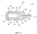
- FIG. 11 is a top plan view of the spring shown in FIG. 9 and in an open position.
- FIG. 12 is a schematic block diagram of an exemplary system for use in determining a cardiac output of a living subject.
- FIG. 13 is a flow chart illustrating an exemplary method for determining a cardiac output of a living subject.
- FIG. 14 is a schematic view of an exemplary human thorax having a plurality of the electrode assemblies shown in FIG. 1 attached thereto.
- FIG. 1 is a top perspective view of an exemplary embodiment of an electrode assembly 10 for use with a living subject (not shown in FIG. 1 ).
- FIG. 2 is a bottom perspective view of electrode assembly 10 .
- FIG. 3 is a partial exploded perspective view of electrode assembly 10 .
- FIG. 4 is a cross-sectional view of a portion of electrode assembly 10 taken along line 4 - 4 (shown in FIG. 1 ).
- FIG. 5 is a cross-sectional view of a portion of electrode assembly 10 taken along line 5 - 5 (shown in FIG. 1 ).
- Electrode assembly 10 generally includes a substrate 12 , a plurality of terminals 14 and 16 for conducting electrical current, and a plurality of electrolytic elements 18 and 19 .
- electrode assembly 10 may include any number of terminals.
- terminals 14 and 16 are sized differently to facilitate coupling of components to terminals 14 and/or 16 in the correct orientation. More specifically, because terminals 14 and 16 are sized differently, terminals 14 and 16 prevent electrical cables from being inadvertently coupled to the wrong terminal 14 and/or 16 .
- Substrate 12 may have any suitable size and/shape, whether described and/or illustrated herein, that enables substrate 12 to function as described herein.
- substrate 12 is sized and/or shaped to conform to certain physical features of the living subject.
- substrate 12 is sized, but is not limited to being sized, with a size and/or shape that conforms to the living subject's thorax, and/or a size and/or shape that conforms to the living subject's neck.
- FIG. 6 illustrates one alternative example of a shape of substrate 12 .
- Substrate 12 may be fabricated from any suitable material(s), whether described and/or illustrated herein, that enables substrate 12 to function as described herein.
- substrate 12 includes a polyethylene foam and/or a vinyl material.
- substrate 12 is formed from a generally flexible material. The material(s) used to fabricate substrate 12 may be selected for compliance and/or flexibility to facilitate enabling substrate 12 to at least partially conform to the contours of the living subject's anatomy, while still maintaining sufficient rigidity such that terminals 14 and 16 remain in a predetermined position and orientation relative to substrate 12 .
- Substrate 12 includes a plurality of openings 20 and 22 that extend therethrough. Terminals 14 and 16 are received within openings 20 and 22 , respectively, such that respective end portions 24 and 26 of terminals 14 and 16 extend a distance outward from and project above an upper surface 21 of substrate 12 . Although substrate 12 is illustrated herein as including only two openings 20 and 22 for receiving two terminals 14 and 16 , respectively, substrate 12 may include any number of openings for receiving any number of terminals. Terminals 14 and 16 may be held in position, and/or orientation, relative to substrate 12 using any suitable structure and/or means, such as, but not limited to, a respective mounting element 28 and 29 (described in more detail below).
- Terminals 14 and 16 may be spaced relative to each other at any suitable distance that enables terminals 14 and 16 to function as described herein.
- a distance between some adjacent terminals may be different that a distance between other adjacent terminals.
- the varied spacing between terminals may facilitate enabling a clinician to select between more than one terminal spacing when coupling electrical cables to two of the terminals.
- Terminals 14 and 16 may each have any size and/or shape that enables terminals 14 and 16 to function as described herein.
- each terminal 14 and 16 includes a respective sidewall portion 30 and 32 that extends between a respective root 34 and 36 and the respective end portion 24 and 26 .
- Terminals 14 and 16 generally conduct electrical current between an electrical connector (not shown in FIGS. 1-6 ) coupled thereto, and the respective root 34 and 36 .
- roots 34 and 36 , sidewall portions 30 and 32 , and end portions 24 and 26 each are fabricated with a generally circular cross-sectional shape.
- each terminal 14 and 16 may have a generally uniform cross-sectional size extending from each root 34 and 36 to each respective end portion 24 and 26
- end portions 24 and 26 each have a diameter 38 and 40 , respectively, that is larger than a respective diameter 42 and 44 of sidewall portions 30 and 32 .
- the increased diameter of end portions 24 and 26 facilitates the attachment of an electrical connector to each terminal 14 and 16 .
- Terminals 14 and 16 may be fabricated from any suitable material(s) that enables terminals 14 and 16 to function as described herein.
- terminals 14 and 16 may be fabricated from, but are not limited to being fabricated from, molded and/or extruded gold, brass, or any other conductive material(s) that enables terminals 14 and 16 to function as described herein.
- terminals 14 and 16 are fabricated from, but are not limited to being fabricated from, an extruded metal such as but not limited to, nickel, having a metallic coating, such as, but not limited to, brass and/or gold.
- terminals 14 and 16 are fabricated from a molded carbon terminal.
- terminals 14 and 16 are fabricated as a molded plastic terminal having a metallic coating, such as, but not limited to, brass and/or gold. In yet another embodiment, terminals 14 and 16 are fabricated as a molded plastic terminal that has been impregnated with carbon.
- each terminal 14 and 16 may generally be fabricated as a “one-piece” construction (possibly including a coating and/or impregnated particles), in the exemplary embodiment terminals 14 and 16 are each fabricated as a “multi-piece” construction. More specifically, in the exemplary embodiment, each terminal 14 and 16 includes a respective terminal element 46 and 48 and a separate terminal element 50 and 52 , respectively. A post 54 and 56 of each respective terminal element 50 and 52 is received through an opening 58 and 60 formed within the respective mounting element 28 and 29 and is inserted into a cavity 62 and 64 defined within each respective terminal element 46 and 48 .
- each mounting element 28 and 29 is frictionally retained between a flange 66 and 68 extending from each respective terminal element 46 and 48 and a flange 70 and 72 extending from each respective terminal element 50 and 52 .
- terminal elements 46 and 50 form terminal 14
- terminal elements 48 and 52 form terminal 16 .
- terminal elements 50 and/or 52 are coated with any suitable material(s) that facilitates terminals 14 and/or 16 functioning as described herein, such as, but not limited to Ag/AgCl and/or Zinc Chloride.
- Electrolytic elements 18 and 19 are each applied to a lower surface 74 of substrate 12 that is positioned against the living subject's skin. More specifically, electrolytic elements 18 and 19 are applied to surface 74 such that electrolytic elements 18 and 19 each contact the respective terminal 14 and 16 . Generally, electrolytic elements 18 and 19 facilitate conducting electrical current between the respective terminal 14 and 16 and the living subject's skin. In the exemplary embodiment, electrolytic elements 18 and 19 are each applied to substrate surface 74 such that a portion of each element 18 and 19 is received within the respective substrate opening 20 and 22 and contacts a surface 76 and 78 of the respective terminal element 50 and 52 .
- a location, size, shape, configuration, and/or orientation of elements 18 and 19 relative to each respective terminal 14 and 16 may affect the accuracy of the measurement of electrical properties at terminals 14 and 16 .
- electrolytic elements 18 and 19 are applied to substrate surface 74 such that each element 18 and 19 is oriented generally symmetrically about each respective terminal 14 and 16 .
- elements 18 and 19 may each be applied to substrate surface 74 in any suitable orientation, size, shape, configuration, and/or location that enables elements 18 and 19 to function as described herein.
- elements 18 and 19 may each be applied to substrate surface 74 in a non-symmetrical orientation about each respective terminal 14 and 16 to facilitate a predetermined electrolytic condition being produced, for example.
- each element 18 and 19 may be split into a plurality of component parts.
- Electrolytic elements 18 and, 19 may be formed from any suitable material(s) that enables elements 18 and 19 to function as described herein, such as, but not limited to, an ultraviolet cured potassium chloride (KCl) gel.
- UV curing of elements 18 and 19 may facilitate a more solidified consistency and improved mechanical properties, thereby ensuring adequate adhesiveness and/or electrolytic properties are maintained while reducing excessive spreading and/or thinning of elements 18 and 19 when electrode assembly 10 is attached to the living subject's skin.
- Electrode assembly 10 substrate surface 74 may include any suitable adhesive that facilitates removably attaching electrode assembly 10 to the living subject's skin.
- electrolytic element 18 also facilitates adhesion between substrate 12 and the living subject's skin.
- Electrode assembly 10 enables electrical current to be conducted between a current source (not shown in FIGS. 1-6 ) and the living subject's skin.
- a current source not shown in FIGS. 1-6
- electrode assembly 10 is used to determine other properties of the living subject, in the exemplary embodiment electrode assembly 10 is used to determine a cardiac output of the living subject, as is described in more detail below.
- terminal 14 is a stimulation terminal that induces a potential necessary to generate electrical current flowing through a thoracic cavity (not shown) of the living subject
- terminal 16 is a measurement terminal that enables one or more electrical properties used to determine cardiac output to be measured.
- AC electrical current is conducted from a stimulation terminal 14 of one electrode assembly 10 attached to the living subject through the living subject's body to a stimulation terminal 14 of another electrode assembly 10 attached to the living subject. Voltage is then measured between measurement terminals 16 of the two electrode assemblies attached to the living subject.
- the measurement and stimulation terminals are generally fabricated with the same standard size and as such, each of such terminals may be coupled to identically sized electrical connectors (not shown in FIGS. 1-6 ), which are coupled to cables extending from a measurement device (not shown in FIGS. 1-6 ) and/or the electrical current source.
- the electrical connectors may be inadvertently coupled to the wrong terminal, such that the circuit formed by the current source, the living subject's body, and the measurement device is reversed. More specifically, with known electrodes, the electrical connector coupled to the current source may be inadvertently coupled to the measurement terminal and the electrical connector coupled to the measurement device may be inadvertently coupled to the stimulation terminal. Coupling the electrical connectors to the wrong terminals may decrease an accuracy of measurement of an electrical property, thus decreasing an accuracy of the determined cardiac output, and/or may cause mismanagement of the living subject.
- terminals 14 and 16 are sized differently from each other. As such, and for example, a connector (not shown in FIGS. 1-6 ) extending from the electrical cable coupled to the current source may only be coupled to terminal 14 and a connector (not shown in FIGS. 1-6 ) extending from the electrical cable coupled to the measurement device may only be coupled to terminal 16 . As such, terminals 14 and 16 facilitate preventing the measurement device from being inadvertently coupled to the wrong terminal. Any portion of each of terminals 14 or 16 may be sized differently from the same portion of the other terminal 14 or 16 to facilitate preventing the wrong electrical connector from being coupled to terminals 14 or 16 . In the exemplary embodiment, terminal end portion 24 is sized differently than terminal end portion 26 .
- diameter 38 of terminal 14 is larger than the corresponding diameter 40 of terminal 16 .
- terminal diameter 40 is larger than terminal diameter 38 .
- end portion 24 of terminal 14 and end portion 26 of terminal 16 may each have any size, albeit different from each other.
- the diameter 38 of terminal 14 is at least about 0.155 inches, and the diameter 40 of terminal 16 is between about 0.1 inches and about 0.155 inches.
- the diameter 38 of terminal 14 is between about 0.18 inches and about 0.19 inches, and the diameter 40 of terminal 16 is between about 0.12 inches and about 0.13 inches.
- the diameter 38 of terminal 14 is between about 0.1 inches and about 0.155 inches and the diameter 40 of terminal 16 is at least about 0.155 inches.
- the diameter 38 of terminal 14 is between about 0.12 inches and about 0.13 inches, and the diameter 40 of terminal 16 is between about 0.18 inches and about 0.19 inches.
- terminal 14 is described and/or illustrated herein as a stimulation terminal and terminal 16 is described and/or illustrated herein as a measurement terminal for use determining cardiac output of a living subject
- terminals 14 and 16 are described and/or illustrated herein as being differently sized to facilitate preventing the electrical connector coupled to the current source from being inadvertently coupled to measurement terminal 16 and/or the electrical connector coupled to the measurement device from being inadvertently coupled to stimulation terminal 14
- terminals 14 and 16 may be differently sized to facilitate preventing the wrong electrical connector from being inadvertently coupled to terminal 14 and/or terminal 16 in any circuit at least partially formed by the living subject and terminals 14 and 16 .
- terminals 14 and 16 are described and/or illustrated herein as coupled to the same substrate 12 , in other embodiments, terminals 14 and 16 may each be coupled to a separate substrate.
- FIG. 7 is a perspective view of an exemplary embodiment of an electrical connector 100 that may be used with electrode assembly 10 (shown in FIGS. 1-6 ).
- FIG. 8 is an exploded view of electrical connector 100 .
- FIG. 9 is a perspective view of an exemplary embodiment of a spring 102 used with electrical connector 100 .
- Connector 100 facilitates electrically and mechanically coupling an electrical cable 104 , such as, but not limited to, from a current source (not shown in FIGS. 7-9 ), and/or a measurement device (not shown in FIGS. 7-9 ), to a terminal, such as, but not limited to, either terminal 14 (shown in FIGS. 1-6 ) and/or terminal 16 (shown in FIGS. 1-6 ) of electrode assembly 10 .
- connector 100 may be used to couple any electrical cable to any terminal, connector 100 will generally be described herein with respect to electrode assembly 10 .
- Connector 100 includes a housing 106 , spring 102 , and at least one actuator 108 .
- housing 106 includes a plurality of walls 110 and 112 that define an internal cavity 114 within housing 106 .
- a plurality of openings 116 and 118 which will sometimes be referred to herein as holes, extend through wall 112 .
- Holes 116 and 118 are sized to receive a portion of one terminal 14 and/or terminal 16 therein.
- housing 106 may include any number of walls and may be fabricated to be any suitable size, shape, and/or material(s) that enables it to function as described and/or illustrated herein.
- housing 106 may include any number of holes for receiving any number of terminals therein.
- holes 116 and 118 are illustrated and described herein as being formed within wall 112 , in other embodiments, holes 116 and 118 may each be formed within wall 110 or other walls (not shown), if included.
- Spring 102 is positioned within internal cavity 114 and includes a pair of arms 120 and 122 .
- Arm 120 extends between a pair of opposite end portions 124 and 126 .
- arm 122 extends between a pair of opposite end portions 128 and 130 .
- Each arm end portion 124 and 128 is coupled to electrical cable 104 .
- arm end portions 126 and 130 are coupled together.
- a portion 132 and 134 of each respective arm 120 and 122 defines a plurality of openings 136 and 138 .
- openings 136 and 138 are each oriented relative to a respective hole 116 and 118 to enable a portion of a terminal to be received therein.
- both openings 136 and 138 may be oriented relative to a single hole (not shown) in housing 106 that is sized to enable both openings 136 and 138 to receive a terminal extending through the hole.
- Spring arm portions 132 and 134 are biased towards each other and towards a central longitudinal axis 139 of connector 100 in a closed position 140 , as shown in FIG. 10 .
- Portions 132 and 134 may be moved against the bias and away from each other and axis 139 to an open position 142 illustrated in FIG. 11 .
- openings 136 and 138 are each larger than when in closed position 140 .
- openings 136 and 138 are each sized to enable a terminal to be received therein.
- portions 132 or 134 is movable relative to axis 139 and the other portion 132 or 134 .
- portions 132 , 134 are hinged about the interconnection between end portions 126 and 130 . More specifically, in the exemplary embodiment, each spring arm 120 and 122 includes a respective portion 144 and 146 that enables portions 132 and 134 to be moved generally away from each other and axis 139 to open position 142 .
- portions 132 and 134 are sized and shaped relative to, and interconnected with, respective portions 144 and 146 , such that movement of portions 144 and 146 towards each other and axis 139 causes portions 132 and 134 to move away from each other and towards open position 142 .
- portions 144 or 146 is movable relative to axis 139 .
- openings 136 and 138 are each sized and shaped to receive a portion of a respective terminal 14 and 16 therein when the respective terminal 14 and 16 extends through the respective housing hole 116 and 118 .
- portions 132 and 134 each include arcuate 148 and 150 , respectively that substantially mirrors a portion of terminal sidewall portion 30 to be engaged.
- portions 132 and 134 are formed arcuately at a respective section 152 and 154 to facilitate engaging terminal sidewall portion 32 .
- openings 136 and 138 may each be sized and/or shaped to receive, and/or enable, any size and/or shape terminal to be engaged.
- each opening 136 and 138 may be sized and/or shaped to receive differently sized and/or differently shaped terminals.
- openings 136 and 138 are each sized such that the bias of portions 132 and 134 is adjustable to accommodate any of a plurality of differently sized terminals.
- spring 102 may include any number of openings for each receiving any number of terminals.
- Spring 102 may be fabricated from any material(s) that enables spring 102 to function as described herein.
- spring 102 is fabricated from, but is not limited to being fabricated from, steel and/or nickel.
- One specific example of spring 102 is stainless steel with nickel plating.
- connector 100 includes a plurality of actuators 156 and 158 coupled to housing 106 that facilitate moving portions 144 and 146 towards each other and towards axis 139 . More specifically, in the exemplary embodiment actuators 156 and 158 are coupled to housing 106 such that actuators 156 and 158 engage respective portions 144 and 146 to enable movement of respective portions 144 and 146 .
- Actuator 156 includes a pair of opposite end portions 160 and 162
- actuator 158 includes a pair of opposite end portions 164 and 166 .
- end portions 160 and 162 are rotatably coupled to housing 106 using any suitable structure and/or means that enables actuators 156 and 158 to rotate relative to housing 106 about a respective axis of rotation 168 and 170 . More specifically, actuators 156 and 158 engage respective portions 144 and 146 such that rotation of end portions 162 and 166 about respective axes 168 and 170 causes portions 144 and 146 to move towards each other. In the exemplary embodiment, because portions 144 and 146 are biased away from each other towards closed position 140 , actuator end portions 162 and 166 are biased away from each other to a respective position 172 and 174 .
- spring 102 is opened by moving actuators 156 and 158 toward each other, which causes portions 144 and 146 to be moved toward each other. Simultaneously, portions 132 and 134 are moved away from each other and openings 136 and 138 are enlarged from closed position 140 to open position 142 . A terminal may then be received within opening 136 or 138 , and spring 102 may be released to cause portions 132 and 134 to move toward each other and into engagement with the terminal. The bias of portions 132 and 134 toward closed position 140 forces portions 132 and 134 to engage the terminal such that the terminal is electrically coupled to spring 102 , and such that the terminal is retained within the opening 136 or 138 .
- spring 102 When engaged with the terminal, spring 102 may conduct electrical current between the terminal and electrical cable 104 .
- an indicator 176 is coupled to housing 106 and is electrically coupled to spring 102 to visually indicate when electrical current is conducted between electrical cable 104 and the terminal.
- Indicator 176 may be any suitable indicator, such as, but not limited to, a light emitting diode.
- FIG. 12 is a schematic block diagram of an exemplary system 200 used for determining a cardiac output of a living subject.
- System 200 includes two or more electrode assemblies 10 (shown in FIGS. 1-6 ), an alternating current (AC) current source 202 capable of generating a substantially constant current, an electrical cable assembly 204 , and a measurement device 206 . Although four electrode assemblies 10 are illustrated, system 200 may include any number of electrode assemblies 10 greater than one.
- Cable assembly 204 includes a plurality of electrical cables 104 for electrically connecting measurement device 206 to measurement terminal 16 of each electrode assembly and for electrically connecting current source 202 to stimulation terminal 14 of each electrode assembly 10 .
- Measurement device 206 includes a processor 208 having associated algorithms capable of running thereon for performing analysis of the signals measured from measurement terminals 16 , one or more memories 210 in data communication with processor 208 for storing and retrieving program instructions and/or data, an I/O interface 212 (e.g., including analog-to-digital converter) for interfacing data between measurement terminals 16 and processor 208 , a mass storage device 214 in data communication with processor 208 for storing and retrieving data, a display device 216 (with associated display driver, not shown) for providing an output display to a system operator, and an input device 218 for receiving input from the operator.
- processor 208 having associated algorithms capable of running thereon for performing analysis of the signals measured from measurement terminals 16
- one or more memories 210 in data communication with processor 208 for storing and retrieving program instructions and/or data
- an I/O interface 212 e.g., including analog-to-digital converter
- mass storage device 214 in data communication with processor 208 for storing and retrieving data
- processor 208 may be embodied in any variety of forms, such as, but not limited to, a personal computer (PC), patient monitoring module, hand-held computer, and/or other computing device.
- PC personal computer
- cables 104 may include any suitable material(s) enabling cables 104 to function as described and/or illustrated herein, in some embodiments cables 104 include copper and/or aluminum. In some embodiments, cables 104 may be insulated using any suitable insulator, such as, but not limited to, using a polymer-based insulation. Moreover, in some embodiments a length of each of cables 104 may be selected to generally match an impedance of each of cables 104 to each other
- FIG. 13 is a flow chart illustrating an exemplary method 300 for determining a cardiac output of a living subject, for example using system 200 (shown in FIG. 12 ).
- Method 300 includes positioning 302 two or more electrode assemblies 10 on skin of the living subject at predetermined locations above and below the thoracic cavity of the living subject.
- FIG. 14 is a schematic view of a portion of an exemplary human having a plurality of electrode assemblies 10 attached thereto on a thorax and a neck of the human, although any suitable location for each electrode assembly 10 may be used.
- Method 300 includes generating 304 a substantially constant AC current that passes from the current source through stimulation terminal 14 of each electrode assembly 10 and the human's thoracic cavity to the stimulation terminals 14 of the other electrode assemblies 10 .
- Voltage at each measurement terminal 16 is then measured 306 , for example using measurement device 206 .
- the voltage measured at measurement terminals 16 is generally reduced from that applied to stimulation terminals 14 by virtue of the impedance of; among other things, the thoracic cavity.
- the measured voltage at one or more measurement terminals 16 is an absolute voltage.
- the measured voltage at two or more measurement terminals 16 is a differential voltage.
- a cardiac stroke volume is then determined 308 from the measured voltage(s), for example using measurement device 206 .
- a left ventricular ejection time (LVET) and a derivative of impedance is determined, and the cardiac stroke volume is calculated based at least in part of the determined LVET and derivative of impedance.
- LVET left ventricular ejection time
- a cardiac rate is then determined 310 , for example using measurement device 206 .
- the cardiac rate is determined by measuring one or more electrocardiogram (ECG) potentials using one or more measurement terminals 16 , and determining the cardiac rate based at least in part on the measured ECG potential(s).
- measuring one or more ECG potentials includes measuring one or more body surface potentials between two measurement terminals 16 to identify one or more QRS complex events within the human, where Q, R, and S are specific fiducial points within an ECG.
- a frequency of QRS complex events is used to determine cardiac rate.
- Cardiac output is then determined 312 based on the determined 308 stroke volume and the determined 310 cardiac rate, for example using measurement device 206 .
- cardiac output is determined 312 by multiplying the determined 308 stroke volume by the determined 310 cardiac rate.
- electrode assembly 10 described and/or illustrated may facilitate preventing the wrong electrical connector from being coupled to an electrical terminal such that, for example, a circuit is reversed. More specifically, when electrode assembly 10 is used with electrical cables having differently sized connectors, the differently sized terminals of assembly 10 may facilitate preventing the wrong cable from being coupled to the wrong terminal. For example, when electrode assembly 10 used with a living subject, assembly 10 may facilitate preventing an electrical cable coupled to a current source from being inadvertently coupled to a measurement terminal and/or an electrical cable coupled to a measurement device from being inadvertently coupled to a stimulation terminal.
- electrode assembly 10 may facilitate preventing a reversal of a circuit formed by the current source, the stimulation terminal, the living subject's body, the measurement terminal, and the measurement device. Such a reversal may decrease an accuracy of a measurement by the measurement device, which may decrease an accuracy of a determined property of the living subject, and/or may cause mismanagement of the living subject. As such, electrode assembly 10 may facilitate increasing an accuracy of a measurement of by the measurement device, which may facilitate increasing an accuracy of a determined property of the living subject, and/or may facilitate management of the living subject.
- electrical connector 100 described and/or illustrated herein may facilitate reducing and/or eliminating an amount of pressure applied to the terminal, and therefore a living subject when the terminal is used therewith, used to coupled an electrical cable to the terminal.
- connector 100 may facilitate connecting the electrical cable to differently sized terminals.
- assemblies, systems, connectors, and methods described and/or illustrated herein are described and/or illustrated with respect to determining cardiac output of a human subject, and more specifically determining cardiac output using the thorax of the human subject, practice of the assemblies, systems, connectors, and methods described and/or illustrated herein is not limited to using the thorax of a human subject, nor determining cardiac output, nor human subjects generally. Rather, the assemblies, systems, connectors, and methods described and/or illustrated herein are applicable for determining any property of any living subject.
- assemblies, systems, connectors, and methods are described and/or illustrated herein in detail.
- the assemblies, systems, connectors, and methods are not limited to the specific embodiments described herein, but rather, components of each assembly, system, and connector, as well as steps of each method, may be utilized independently and separately from other components and steps described herein.
- Each component, and each method step can also be used in combination with other components and/or method steps.
- the articles “a”, “an”, “the”, “said”, and “at least one” are intended to mean that there are one or more of the element(s)/component(s)/etc.
- the terms “comprising”, “including” and “having” are intended to be inclusive and mean that there may be additional element(s)/component(s)/etc. other than the listed element(s)/component(s)/etc.
Abstract
Description
Claims (21)
Priority Applications (3)
| Application Number | Priority Date | Filing Date | Title |
|---|---|---|---|
| US11/343,839 US7270580B2 (en) | 2004-11-22 | 2006-01-31 | Methods and apparatus for conducting electrical current |
| PCT/US2006/033583 WO2007089278A1 (en) | 2006-01-31 | 2006-08-25 | Methods and apparatus for conducting electrical current |
| CN2006800532454A CN101385203B (en) | 2006-01-31 | 2006-08-25 | Methods and apparatus for conducting electrical current |
Applications Claiming Priority (2)
| Application Number | Priority Date | Filing Date | Title |
|---|---|---|---|
| US10/995,610 US7214107B2 (en) | 2004-11-22 | 2004-11-22 | Electrical connector apparatus and methods |
| US11/343,839 US7270580B2 (en) | 2004-11-22 | 2006-01-31 | Methods and apparatus for conducting electrical current |
Related Parent Applications (1)
| Application Number | Title | Priority Date | Filing Date |
|---|---|---|---|
| US10/995,610 Continuation-In-Part US7214107B2 (en) | 2004-11-22 | 2004-11-22 | Electrical connector apparatus and methods |
Publications (2)
| Publication Number | Publication Date |
|---|---|
| US20060128193A1 US20060128193A1 (en) | 2006-06-15 |
| US7270580B2 true US7270580B2 (en) | 2007-09-18 |
Family
ID=38327715
Family Applications (1)
| Application Number | Title | Priority Date | Filing Date |
|---|---|---|---|
| US11/343,839 Active US7270580B2 (en) | 2004-11-22 | 2006-01-31 | Methods and apparatus for conducting electrical current |
Country Status (3)
| Country | Link |
|---|---|
| US (1) | US7270580B2 (en) |
| CN (1) | CN101385203B (en) |
| WO (1) | WO2007089278A1 (en) |
Cited By (25)
| Publication number | Priority date | Publication date | Assignee | Title |
|---|---|---|---|---|
| US20090182394A1 (en) * | 2008-01-07 | 2009-07-16 | Thomas Jerome Bachinski | Systems and methods for therapeutic electrical stimulation |
| US20090182393A1 (en) * | 2008-01-07 | 2009-07-16 | Thomas Jerome Bachinski | Systems and methods for therapeutic electrical stimulation |
| US20100036231A1 (en) * | 2008-08-08 | 2010-02-11 | Anatolie Hobet | Electrical connector apparatus and methods |
| WO2010132923A1 (en) * | 2009-05-18 | 2010-11-25 | Impedimed Limited | Electrode assembly |
| US20120088396A1 (en) * | 2008-08-27 | 2012-04-12 | Bio Protech Inc. | Lead wire for connecting to tab electrode |
| US8197276B2 (en) | 2010-08-13 | 2012-06-12 | Djo, Llc | Low profile connector system |
| US8233974B2 (en) | 1999-06-22 | 2012-07-31 | Impedimed Limited | Method and device for measuring tissue oedema |
| US8487686B2 (en) | 2007-03-30 | 2013-07-16 | Impedimed Limited | Active guarding for reduction of resistive and capacitive signal loading with adjustable control of compensation level |
| US8761870B2 (en) | 2006-05-30 | 2014-06-24 | Impedimed Limited | Impedance measurements |
| US9107594B2 (en) | 2007-12-11 | 2015-08-18 | Covidien Lp | ECG electrode connector |
| USD737979S1 (en) * | 2008-12-09 | 2015-09-01 | Covidien Lp | ECG electrode connector |
| US9408546B2 (en) | 2013-03-15 | 2016-08-09 | Covidien Lp | Radiolucent ECG electrode system |
| US9408547B2 (en) | 2011-07-22 | 2016-08-09 | Covidien Lp | ECG electrode connector |
| USD771818S1 (en) | 2013-03-15 | 2016-11-15 | Covidien Lp | ECG electrode connector |
| US9504406B2 (en) | 2006-11-30 | 2016-11-29 | Impedimed Limited | Measurement apparatus |
| US9615766B2 (en) | 2008-11-28 | 2017-04-11 | Impedimed Limited | Impedance measurement process |
| US9662024B2 (en) | 2012-02-16 | 2017-05-30 | New N.I. Medical (2011) Ltd. | Biomedical electrode assembly |
| US9693701B2 (en) | 2013-03-15 | 2017-07-04 | Covidien Lp | Electrode connector design to aid in correct placement |
| US9724012B2 (en) | 2005-10-11 | 2017-08-08 | Impedimed Limited | Hydration status monitoring |
| US20170258357A1 (en) * | 2014-06-13 | 2017-09-14 | Markus Riemenschneider | Intelligent electrode |
| US9819122B1 (en) * | 2016-06-29 | 2017-11-14 | Intel Corporation | Apparel compute device connection |
| US9859642B2 (en) * | 2016-05-19 | 2018-01-02 | Japan Aviation Electronics Industry, Limited | Connector and method for using connector |
| US10307074B2 (en) | 2007-04-20 | 2019-06-04 | Impedimed Limited | Monitoring system and probe |
| USD898202S1 (en) * | 2017-11-12 | 2020-10-06 | Dms-Service Llc | Patch with electrode array |
| USD907213S1 (en) * | 2017-09-18 | 2021-01-05 | Dms-Service Llc | Patch with electrode array |
Families Citing this family (7)
| Publication number | Priority date | Publication date | Assignee | Title |
|---|---|---|---|---|
| US10699206B2 (en) * | 2009-04-22 | 2020-06-30 | Rodrigo E. Teixeira | Iterative probabilistic parameter estimation apparatus and method of use therefor |
| CN101999896A (en) * | 2010-12-03 | 2011-04-06 | 青岛光电医疗科技有限公司 | Clasped lead electrode |
| CN103784133B (en) * | 2014-02-28 | 2016-04-13 | 思澜科技(成都)有限公司 | A kind of disposable medical electrode sheet |
| CN103908240B (en) * | 2014-04-03 | 2016-08-17 | 深圳市太极医疗科技有限公司 | A kind of body electrical signals monitoring electrode slice |
| CN104300312A (en) * | 2014-10-09 | 2015-01-21 | 江苏泽康医疗科技有限公司 | Button type connector used for electronic impulse treatment instrument |
| EP3527129A1 (en) * | 2018-02-20 | 2019-08-21 | Koninklijke Philips N.V. | Ecg connector and ecg cable |
| CN109171677A (en) * | 2018-09-20 | 2019-01-11 | 芯海科技(深圳)股份有限公司 | A kind of Portable type measurement unit and the hemodynamic parameter measurement method based on the device |
Citations (14)
| Publication number | Priority date | Publication date | Assignee | Title |
|---|---|---|---|---|
| US4299231A (en) | 1977-06-18 | 1981-11-10 | Beiersdorf Aktiengesellschaft | Electrically conductive, visco-elastic gel and its use in electrode |
| US4331153A (en) | 1980-11-13 | 1982-05-25 | Healy James W | Disposable EKG electrode |
| US5184620A (en) | 1991-12-26 | 1993-02-09 | Marquette Electronics, Inc. | Method of using a multiple electrode pad assembly |
| US5562607A (en) * | 1995-01-18 | 1996-10-08 | Alza Corporation | Electrotransport device having reusable controller power saver |
| US5645063A (en) | 1995-06-05 | 1997-07-08 | Quinton Instrument Company | Skin electrode having multiple conductive center members |
| US5660177A (en) | 1991-11-04 | 1997-08-26 | Biofield Corp. | D.C. biopotential sensing electrode assemblies for apparatus for disease, injury and bodily condition screening or sensing |
| US5895298A (en) | 1997-05-29 | 1999-04-20 | Biofield Corp. | DC biopotential electrode connector and connector condition sensor |
| US6064901A (en) * | 1996-12-17 | 2000-05-16 | Ndm, Inc. | Biomedical electrode having a disposable electrode and a reusable leadwire adapter that interfaces with a standard leadwire connector |
| USD468433S1 (en) | 2000-08-28 | 2003-01-07 | Cardiodynamics International Corp. | Electrode for use on a living subject |
| USD471281S1 (en) | 2000-07-10 | 2003-03-04 | Cardiodynamics International Corporation | Electrode for use on a living subject |
| US6561986B2 (en) | 2001-01-17 | 2003-05-13 | Cardiodynamics International Corporation | Method and apparatus for hemodynamic assessment including fiducial point detection |
| USD475138S1 (en) | 2001-10-31 | 2003-05-27 | Cardiodynamics International Corporation | Electrode for use on a living subject with removable protective electrode carrier |
| US6602201B1 (en) | 2000-07-10 | 2003-08-05 | Cardiodynamics International Corporation | Apparatus and method for determining cardiac output in a living subject |
| US6636754B1 (en) | 2000-07-10 | 2003-10-21 | Cardiodynamics International Corporation | Apparatus and method for determining cardiac output in a living subject |
-
2006
- 2006-01-31 US US11/343,839 patent/US7270580B2/en active Active
- 2006-08-25 WO PCT/US2006/033583 patent/WO2007089278A1/en active Application Filing
- 2006-08-25 CN CN2006800532454A patent/CN101385203B/en active Active
Patent Citations (14)
| Publication number | Priority date | Publication date | Assignee | Title |
|---|---|---|---|---|
| US4299231A (en) | 1977-06-18 | 1981-11-10 | Beiersdorf Aktiengesellschaft | Electrically conductive, visco-elastic gel and its use in electrode |
| US4331153A (en) | 1980-11-13 | 1982-05-25 | Healy James W | Disposable EKG electrode |
| US5660177A (en) | 1991-11-04 | 1997-08-26 | Biofield Corp. | D.C. biopotential sensing electrode assemblies for apparatus for disease, injury and bodily condition screening or sensing |
| US5184620A (en) | 1991-12-26 | 1993-02-09 | Marquette Electronics, Inc. | Method of using a multiple electrode pad assembly |
| US5562607A (en) * | 1995-01-18 | 1996-10-08 | Alza Corporation | Electrotransport device having reusable controller power saver |
| US5645063A (en) | 1995-06-05 | 1997-07-08 | Quinton Instrument Company | Skin electrode having multiple conductive center members |
| US6064901A (en) * | 1996-12-17 | 2000-05-16 | Ndm, Inc. | Biomedical electrode having a disposable electrode and a reusable leadwire adapter that interfaces with a standard leadwire connector |
| US5895298A (en) | 1997-05-29 | 1999-04-20 | Biofield Corp. | DC biopotential electrode connector and connector condition sensor |
| USD471281S1 (en) | 2000-07-10 | 2003-03-04 | Cardiodynamics International Corporation | Electrode for use on a living subject |
| US6602201B1 (en) | 2000-07-10 | 2003-08-05 | Cardiodynamics International Corporation | Apparatus and method for determining cardiac output in a living subject |
| US6636754B1 (en) | 2000-07-10 | 2003-10-21 | Cardiodynamics International Corporation | Apparatus and method for determining cardiac output in a living subject |
| USD468433S1 (en) | 2000-08-28 | 2003-01-07 | Cardiodynamics International Corp. | Electrode for use on a living subject |
| US6561986B2 (en) | 2001-01-17 | 2003-05-13 | Cardiodynamics International Corporation | Method and apparatus for hemodynamic assessment including fiducial point detection |
| USD475138S1 (en) | 2001-10-31 | 2003-05-27 | Cardiodynamics International Corporation | Electrode for use on a living subject with removable protective electrode carrier |
Non-Patent Citations (1)
| Title |
|---|
| European Search Report and Opinion, European Patent Office, International Appln. No. PCT/US06/33583, Date of Completion of Search Feb. 2, 2007. |
Cited By (50)
| Publication number | Priority date | Publication date | Assignee | Title |
|---|---|---|---|---|
| US8233974B2 (en) | 1999-06-22 | 2012-07-31 | Impedimed Limited | Method and device for measuring tissue oedema |
| US9724012B2 (en) | 2005-10-11 | 2017-08-08 | Impedimed Limited | Hydration status monitoring |
| US11612332B2 (en) | 2005-10-11 | 2023-03-28 | Impedimed Limited | Hydration status monitoring |
| US8761870B2 (en) | 2006-05-30 | 2014-06-24 | Impedimed Limited | Impedance measurements |
| US9504406B2 (en) | 2006-11-30 | 2016-11-29 | Impedimed Limited | Measurement apparatus |
| US8487686B2 (en) | 2007-03-30 | 2013-07-16 | Impedimed Limited | Active guarding for reduction of resistive and capacitive signal loading with adjustable control of compensation level |
| US10307074B2 (en) | 2007-04-20 | 2019-06-04 | Impedimed Limited | Monitoring system and probe |
| US9107594B2 (en) | 2007-12-11 | 2015-08-18 | Covidien Lp | ECG electrode connector |
| US9044587B2 (en) | 2008-01-07 | 2015-06-02 | Empi Inc. | Systems and methods for therapeutic electrical stimulation |
| US9643006B2 (en) | 2008-01-07 | 2017-05-09 | Djo, Llc | Systems and methods for therapeutic electrical stimulation |
| US8386032B2 (en) | 2008-01-07 | 2013-02-26 | Empi Inc. | Systems and methods for therapeutic electrical stimulation |
| US10071237B2 (en) | 2008-01-07 | 2018-09-11 | Djo, Llc | Systems and methods for therapeutic electrical stimulation |
| US8768473B2 (en) | 2008-01-07 | 2014-07-01 | Empi Inc. | Systems and methods for therapeutic electrical stimulation |
| US8798739B2 (en) | 2008-01-07 | 2014-08-05 | Empi Inc. | Systems and methods for therapeutic electrical stimulation |
| US20090182393A1 (en) * | 2008-01-07 | 2009-07-16 | Thomas Jerome Bachinski | Systems and methods for therapeutic electrical stimulation |
| US8977366B2 (en) | 2008-01-07 | 2015-03-10 | Empi Inc. | Systems and methods for therapeutic electrical stimulation |
| US9943683B2 (en) | 2008-01-07 | 2018-04-17 | Djo, Llc | Systems and methods for therapeutic electrical stimulation |
| US9737705B2 (en) | 2008-01-07 | 2017-08-22 | Djo, Llc | Systems and methods for therapeutic electrical stimulation |
| US10610683B2 (en) | 2008-01-07 | 2020-04-07 | Djo, Llc | Systems and methods for therapeutic electrical stimulation |
| US9220896B2 (en) | 2008-01-07 | 2015-12-29 | Empi Inc. | Systems and methods for therapeutic electrical stimulation |
| US9242091B2 (en) | 2008-01-07 | 2016-01-26 | Empi Inc. | Systems and methods for therapeutic electrical stimulation |
| US10967170B2 (en) | 2008-01-07 | 2021-04-06 | Djo, Llc | Systems and methods for therapeutic electrical stimulation |
| US8452409B2 (en) | 2008-01-07 | 2013-05-28 | Empi Inc. | Systems and methods for therapeutic electrical stimulation |
| US20090182394A1 (en) * | 2008-01-07 | 2009-07-16 | Thomas Jerome Bachinski | Systems and methods for therapeutic electrical stimulation |
| US11364379B2 (en) | 2008-01-07 | 2022-06-21 | Djo, Llc | Systems and methods for therapeutic electrical stimulation |
| US7950971B2 (en) | 2008-08-08 | 2011-05-31 | Cardiodynamics International Corporation | Electrical connector apparatus and methods |
| US20100036231A1 (en) * | 2008-08-08 | 2010-02-11 | Anatolie Hobet | Electrical connector apparatus and methods |
| US20120088396A1 (en) * | 2008-08-27 | 2012-04-12 | Bio Protech Inc. | Lead wire for connecting to tab electrode |
| US9615766B2 (en) | 2008-11-28 | 2017-04-11 | Impedimed Limited | Impedance measurement process |
| USD737979S1 (en) * | 2008-12-09 | 2015-09-01 | Covidien Lp | ECG electrode connector |
| WO2010132923A1 (en) * | 2009-05-18 | 2010-11-25 | Impedimed Limited | Electrode assembly |
| US9356393B2 (en) | 2010-08-13 | 2016-05-31 | Djo, Llc | Low profile connector system |
| US8821176B2 (en) | 2010-08-13 | 2014-09-02 | Djo, Llc | Low profile connector system |
| US8197276B2 (en) | 2010-08-13 | 2012-06-12 | Djo, Llc | Low profile connector system |
| US9768552B2 (en) | 2010-08-13 | 2017-09-19 | Djo, Llc | Low profile connector system |
| US9408547B2 (en) | 2011-07-22 | 2016-08-09 | Covidien Lp | ECG electrode connector |
| US9737226B2 (en) | 2011-07-22 | 2017-08-22 | Covidien Lp | ECG electrode connector |
| US9966694B2 (en) | 2012-02-16 | 2018-05-08 | New N.I. Medical (2011) Ltd | Biomedical electrode assembly |
| US9662024B2 (en) | 2012-02-16 | 2017-05-30 | New N.I. Medical (2011) Ltd. | Biomedical electrode assembly |
| US9814404B2 (en) | 2013-03-15 | 2017-11-14 | Covidien Lp | Radiolucent ECG electrode system |
| US9693701B2 (en) | 2013-03-15 | 2017-07-04 | Covidien Lp | Electrode connector design to aid in correct placement |
| USD771818S1 (en) | 2013-03-15 | 2016-11-15 | Covidien Lp | ECG electrode connector |
| US9408546B2 (en) | 2013-03-15 | 2016-08-09 | Covidien Lp | Radiolucent ECG electrode system |
| US20170258357A1 (en) * | 2014-06-13 | 2017-09-14 | Markus Riemenschneider | Intelligent electrode |
| US9859642B2 (en) * | 2016-05-19 | 2018-01-02 | Japan Aviation Electronics Industry, Limited | Connector and method for using connector |
| US9819122B1 (en) * | 2016-06-29 | 2017-11-14 | Intel Corporation | Apparel compute device connection |
| US20180294601A1 (en) * | 2016-06-29 | 2018-10-11 | Intel Corporation | Apparel compute device connection |
| US10320117B2 (en) * | 2016-06-29 | 2019-06-11 | Intel Corporation | Apparel compute device connection |
| USD907213S1 (en) * | 2017-09-18 | 2021-01-05 | Dms-Service Llc | Patch with electrode array |
| USD898202S1 (en) * | 2017-11-12 | 2020-10-06 | Dms-Service Llc | Patch with electrode array |
Also Published As
| Publication number | Publication date |
|---|---|
| CN101385203B (en) | 2013-02-13 |
| CN101385203A (en) | 2009-03-11 |
| WO2007089278A1 (en) | 2007-08-09 |
| US20060128193A1 (en) | 2006-06-15 |
Similar Documents
| Publication | Publication Date | Title |
|---|---|---|
| US7270580B2 (en) | Methods and apparatus for conducting electrical current | |
| US6636754B1 (en) | Apparatus and method for determining cardiac output in a living subject | |
| US6602201B1 (en) | Apparatus and method for determining cardiac output in a living subject | |
| JP4981688B2 (en) | Multiconductor connection device for medical sensors | |
| US7251524B1 (en) | Apparatus and method for determining cardiac output in a living subject | |
| US6282440B1 (en) | Method to identify electrode placement | |
| US20240032814A1 (en) | Impedance measurement system | |
| US11207016B2 (en) | Mapping ECG signals using a multipole electrode assembly | |
| Bosnjak et al. | Performance assessment of dry electrodes for wearable long term cardiac rhythm monitoring: Skin-electrode impedance spectroscopy | |
| Kadanec et al. | ProCardio 8—System for high resolution ECG mapping | |
| CN105476625A (en) | Portable electrocardiogram monitor | |
| EP3505060A1 (en) | Body composition measurement using clamp electrodes | |
| US7856261B2 (en) | Cable with spacer for positioning multiple medical sensors | |
| CN215778203U (en) | Portable heart multi-parameter monitor and system | |
| CN211401489U (en) | Disposable body temperature probe and detector | |
| CN113729760A (en) | Portable heart multi-parameter monitor and system | |
| JP4536510B2 (en) | Electrode detector for monitoring tissue biopotential | |
| WO2022214850A1 (en) | System for monitoring a vital sign | |
| CN111214229A (en) | Compensating for artifacts during tracking of an in vivo probe | |
| WO2020076955A1 (en) | A probe having multiple tips and an indicator for obtaining bioelectrical signals | |
| Fukumoto et al. | Temporal resolution of the skin impedance measurement in Frequency-Domain method | |
| CN108652602A (en) | A kind of desktop machine people | |
| JP2001212094A (en) | Calibrator for measuring equipment for electrical characteristics | |
| Pandey | An Embedded Design Example: A Thorax Simulator for Testing and Calibration of Impedance Cardiographs | |
| JP2001204702A (en) | Electrical characteristic-measuring instrument |
Legal Events
| Date | Code | Title | Description |
|---|---|---|---|
| AS | Assignment |
Owner name: CARDIO DYNAMICS INTERNATIONAL CORPORATION, CALIFOR Free format text: ASSIGNMENT OF ASSIGNORS INTEREST;ASSIGNORS:BRADLEY, PATRICK WALTON;BAURA, GAIL DAWN;REEL/FRAME:017533/0623 Effective date: 20060130 |
|
| AS | Assignment |
Owner name: COMERICA BANK, CALIFORNIA Free format text: SECURITY AGREEMENT;ASSIGNOR:CARDIODYNAMICS INTERNATIONAL CORPORATION;REEL/FRAME:018180/0092 Effective date: 20060804 |
|
| AS | Assignment |
Owner name: COMERICA BANK, CALIFORNIA Free format text: SECURITY AGREEMENT;ASSIGNOR:CARDIODYNAMICS INTERNATIONAL CORPORATION;REEL/FRAME:018847/0277 Effective date: 20060804 |
|
| STCF | Information on status: patent grant |
Free format text: PATENTED CASE |
|
| AS | Assignment |
Owner name: CARDIODYNAMICS INTERNATIONAL CORPORATION, CALIFORN Free format text: RELEASE BY SECURED PARTY;ASSIGNOR:COMERICA BANK;REEL/FRAME:019817/0791 Effective date: 20070911 |
|
| FPAY | Fee payment |
Year of fee payment: 4 |
|
| FEPP | Fee payment procedure |
Free format text: PAYER NUMBER DE-ASSIGNED (ORIGINAL EVENT CODE: RMPN); ENTITY STATUS OF PATENT OWNER: LARGE ENTITY Free format text: PAYOR NUMBER ASSIGNED (ORIGINAL EVENT CODE: ASPN); ENTITY STATUS OF PATENT OWNER: LARGE ENTITY |
|
| FEPP | Fee payment procedure |
Free format text: PAYOR NUMBER ASSIGNED (ORIGINAL EVENT CODE: ASPN); ENTITY STATUS OF PATENT OWNER: LARGE ENTITY |
|
| AS | Assignment |
Owner name: SONOSITE, INC., WASHINGTON Free format text: MERGER;ASSIGNOR:CARDIODYNAMICS INTERNATIONAL CORPORATION;REEL/FRAME:031374/0593 Effective date: 20090813 Owner name: FUJIFILM SONOSITE, INC., WASHINGTON Free format text: CHANGE OF NAME;ASSIGNOR:SONOSITE, INC.;REEL/FRAME:031394/0392 Effective date: 20120924 |
|
| FPAY | Fee payment |
Year of fee payment: 8 |
|
| MAFP | Maintenance fee payment |
Free format text: PAYMENT OF MAINTENANCE FEE, 12TH YEAR, LARGE ENTITY (ORIGINAL EVENT CODE: M1553); ENTITY STATUS OF PATENT OWNER: LARGE ENTITY Year of fee payment: 12 |