US7242926B1 - Communication device and communication system - Google Patents
Communication device and communication system Download PDFInfo
- Publication number
- US7242926B1 US7242926B1 US09/635,011 US63501100A US7242926B1 US 7242926 B1 US7242926 B1 US 7242926B1 US 63501100 A US63501100 A US 63501100A US 7242926 B1 US7242926 B1 US 7242926B1
- Authority
- US
- United States
- Prior art keywords
- image information
- electronic mail
- regional
- regional image
- Prior art date
- Legal status (The legal status is an assumption and is not a legal conclusion. Google has not performed a legal analysis and makes no representation as to the accuracy of the status listed.)
- Expired - Fee Related, expires
Links
Images


Classifications
-
- H—ELECTRICITY
- H04—ELECTRIC COMMUNICATION TECHNIQUE
- H04L—TRANSMISSION OF DIGITAL INFORMATION, e.g. TELEGRAPHIC COMMUNICATION
- H04L9/00—Cryptographic mechanisms or cryptographic arrangements for secret or secure communications; Network security protocols
- H04L9/40—Network security protocols
-
- H—ELECTRICITY
- H04—ELECTRIC COMMUNICATION TECHNIQUE
- H04M—TELEPHONIC COMMUNICATION
- H04M1/00—Substation equipment, e.g. for use by subscribers
- H04M1/72—Mobile telephones; Cordless telephones, i.e. devices for establishing wireless links to base stations without route selection
- H04M1/724—User interfaces specially adapted for cordless or mobile telephones
- H04M1/72403—User interfaces specially adapted for cordless or mobile telephones with means for local support of applications that increase the functionality
- H04M1/7243—User interfaces specially adapted for cordless or mobile telephones with means for local support of applications that increase the functionality with interactive means for internal management of messages
- H04M1/72439—User interfaces specially adapted for cordless or mobile telephones with means for local support of applications that increase the functionality with interactive means for internal management of messages for image or video messaging
-
- H—ELECTRICITY
- H04—ELECTRIC COMMUNICATION TECHNIQUE
- H04L—TRANSMISSION OF DIGITAL INFORMATION, e.g. TELEGRAPHIC COMMUNICATION
- H04L51/00—User-to-user messaging in packet-switching networks, transmitted according to store-and-forward or real-time protocols, e.g. e-mail
- H04L51/58—Message adaptation for wireless communication
-
- H—ELECTRICITY
- H04—ELECTRIC COMMUNICATION TECHNIQUE
- H04L—TRANSMISSION OF DIGITAL INFORMATION, e.g. TELEGRAPHIC COMMUNICATION
- H04L67/00—Network arrangements or protocols for supporting network services or applications
- H04L67/50—Network services
- H04L67/52—Network services specially adapted for the location of the user terminal
-
- H—ELECTRICITY
- H04—ELECTRIC COMMUNICATION TECHNIQUE
- H04L—TRANSMISSION OF DIGITAL INFORMATION, e.g. TELEGRAPHIC COMMUNICATION
- H04L69/00—Network arrangements, protocols or services independent of the application payload and not provided for in the other groups of this subclass
- H04L69/30—Definitions, standards or architectural aspects of layered protocol stacks
- H04L69/32—Architecture of open systems interconnection [OSI] 7-layer type protocol stacks, e.g. the interfaces between the data link level and the physical level
- H04L69/322—Intralayer communication protocols among peer entities or protocol data unit [PDU] definitions
- H04L69/329—Intralayer communication protocols among peer entities or protocol data unit [PDU] definitions in the application layer [OSI layer 7]
Definitions
- the present invention relates to a communication device such as a PHS terminal which provides not only a function for communicating mail documents but also a function for communicating information specific to the current position, as well as a communication system using such a communication device.
- Recent digital cellular telephones and PHS (Personal Handyphone System: second-generation codeless telephone system) terminals can transmit not only voices but also mail documents or handwritten images.
- PHS Personal Handyphone System: second-generation codeless telephone system
- addition of information specific to the current position of the terminal for example, an image representing a scene peculiar to that region
- a communication device comprising mail creation means for creating an electronic mail, means for detecting the current position of the communication device, and transmission means for attaching information corresponding to the current position to the electronic mail and transmitting the electronic mail with the information being attached.
- another radio communication system comprising a communication terminal, and a cell station connecting to the communication terminal via a radio channel
- the communication terminal comprises mail creation means for creating an electronic mail, means for detecting the current position of the communication device, and transmission means for attaching information corresponding to the current position to the electronic mail and transmitting the electronic mail with the information being attached.
- a still another radio communication system comprising a communication terminal, and a cell station connecting to the communication terminal via a radio channel
- the communication terminal comprises mail creation means for creating an electronic mail, means for detecting the current position of the communication device, and transmission means for attaching position information indicating the current position to the electronic mail and transmitting the electronic mail with the position information being attached to the cell station
- the cell station comprises means for attaching regional information corresponding to the current position based on the position information and for transmitting the electronic mail with the regional information being attached.
- FIG. 1 is a view showing the entire configuration of a communication system according to a first embodiment of the present invention
- FIG. 2 is a block diagram showing the configuration of a circuit in a PHS terminal according to the first embodiment
- FIG. 3 is a flow chart showing a process carried out in a mail creation mode according to the first embodiment of the present invention
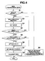
- FIG. 4 is a flow chart showing how a mail is created with a PHS terminal according to a second embodiment of the present invention.
- FIG. 5 is a flow chart showing how mail documents are received at a service center according to the second embodiment of the present invention.
- FIG. 1 shows the configuration of a communication system according to the first embodiment where the present invention is applied to a communication service (in this case, the PHS) that can transmit and receive regional images and mail documents using bit maps.
- a communication service in this case, the PHS
- a large number of PHS cell stations (CS) 2 - 1 , 2 - 2 , 2 -N are connected to a network (the PSTN, the ISDN, or the like), and a service center operated by a service company that provides services for transmitting regional images and mail documents through the PHS is also connected to the network.
- CS PHS cell stations
- the PHS terminals (only two are shown, but the number is not limited to two) 4 a and 4 b can each communicate by executing a position registration process with one of the cell stations 2 - 1 , 2 - 2 , . . . 2 -N.
- the PHS terminals 4 a and 5 b are adapted for communication services for enabling regional images and mail documents to be transmitted and received and are registered in the service center 3 by contracting with the service company.
- FIG. 2 shows the configuration of a circuit in each of the PHS terminal 4 a and 4 b .
- a transmission and reception section 12 is connected to an antenna 11 .
- the transmission and reception section 12 comprises an antenna switch for assigning transmissions/receptions to corresponding addresses, a frequency conversion section for converting frequency between radio signals and IF signals, and a modem.
- the frequency conversion section accepts inputs via the antenna switch of signals received by the antenna 11 and converts a radio signal in a 1.9-GHz zone into an IF signal in a 1-MHz zone by mixing the signal with a local oscillation signal of a predetermined frequency output from a PLL synthesizer, not shown.
- the IF signal is supplied to the modem.
- the frequency conversion section mixes a ⁇ /4 shift GPSK modulated wave (the IF signal) with a local oscillation signal of a predetermined frequency output from the PLL synthesizer, to convert the IF signal in the 1-MHz zone into the radio signal in the 1.9-GHz zone, and then emits the signal from the antenna 11 via the antenna switch.
- the modem demodulates the IF signal from the frequency conversion section to separate it into I and Q data, which are then transferred to a communication control section 13 .
- the modem generates the I and Q data from the data transferred from the communication control section 13 and subjects the data to the ⁇ /4 shift QPSK conversion before outputting them to the frequency conversion section.
- the communication control section 13 is connected to the transmission and reception section 12 and a voice processing section 14 is connected to the communication control section 13 .
- a receiving speaker 15 and a transmitting microphone 16 is connected to the voice processing section 14 .
- the communication control section 13 executes frame synchronization and slot data formatting.
- the receiver uses a predetermined timing to obtain one slot of data from received data transmitted from the modem of the transmission and reception section 12 , extracts a unique word (a synchronization signal) from the data for frame synchronization, descrambles control data, voice data, or communication data, and transmits the control and communication data to a control section 17 , described later, while transferring the voice data to the voice processing section 14 .
- a unique word a synchronization signal
- the sender adds control data to the voice data transmitted from the voice processing section 14 or to the communication data transmitted from the control section 17 , to scramble these data, subsequently adds a unique word or the like to the data to create one slot of transmitted data, then inserts the data into a predetermined slot within a frame using a predetermined timing, and finally transmits the data to the modem of the transmission and reception section 12 .
- the voice processing section 14 comprises a speech CODEC and a PCM CODEC.
- the speech CODEC compresses/expands digital data.
- the sender compresses the PCM voice signal transmitted from the PCM CODEC, by coding it into the ADPCM voice signal, and then outputs the compressed signal to the communication control section 13 .
- the PCM CODEC executes an analog/digital conversion process.
- the receiver subjects a PCM voice signal transmitted from the speech CODEC to a D/A conversion and outputs the obtained analog voice signal to the speaker 15 .
- the sender subjects the analog voice signal input from the microphone 16 to an A/D conversion to obtain the PCM voice signal and outputs it to the speech CODEC.
- the transmission and reception section 12 , communication control section 13 , and voice processing section 14 are connected to the control section 17 , which connects to a display section 18 , key input section 19 , ROM 20 , RAM 21 , and transmission and reception buffer 22 .
- the control section 17 comprises a CPU or the like to control the entire device based on a predetermined program stored in the ROM 20 .
- the ROM 20 stores programs for control operations such as communication controls, speech data transmissions and receptions, and creation and transmission of mail documents and regional images which are all executed by the control section 17 , character pattern data corresponding to a character text code, regional image data as stamp images which correspond to areas to which identification information (hereafter simply referred to as “CS-ID”) on the cell stations 2 - 1 , 2 - 2 , . . . 2 -N throughout Japan is assigned (the regional image data indicates a scene, a logo mark, or the like of each area), and other data.
- CS-ID identification information
- the RAM 21 has a work area for temporarily storing various data used by the control section 17 for controls, a mail area that stores predetermined numbers of various mail data including transmitted voice data, character text data, and image data, and a directory area that stores sets of destinations and their telephone numbers or mail addresses.
- the display section 18 comprises a dot matrix liquid-crystal display panel with a back light which can display, for example, binary image data of 130 ⁇ 192 dots, and a drive circuit for the display panel.
- the key input section 19 has a dial key, a “send” key, an “off” key, a mode selection key, a cursor key, and other keys for inputting to the control section 17 a key operation signal for setting a corresponding function.
- the transmission and reception buffer 22 comprises a transmission buffer area and a reception buffer area which buffers data to be transmitted and received, respectively.
- a user selects as a sending mode either a normal mode that operates to transmit the mail document as it is and a stamp attachment mode that automatically selects as a stamp image (information specific to the area) a regional image corresponding to the CS-ID on the nearest cell station 2 and attaching the selected image to the mail document for transmission.
- FIG. 3 illustrates a process executed by the PHS terminal 4 a or 4 b if the mode selection key of the key input section 19 is used to select the mail sending mode.
- step A 1 It is determined whether or not the PHS terminal is located within a corresponding communication range (step A 1 ). If it is not located within the communication range, a created mail document cannot be transmitted, so that the display section 18 displays a guide message, for example, “Out of communication range. You can't send mail. Move into communication range” (step A 10 ) and the speaker 15 emits an intermittent beep sound. Thus, the process is ended and waits for the user to move into the communication range.
- the CS-ID on the cell station 2 is temporarily held in a register for the work area of the RAM 21 as positional information indicating the current position of the terminal.
- a mail creation process corresponding to a key input on the key input section 19 is sequentially executed. Then, the user specifies the destination of the mail document by using the cursor key to select one of the telephone numbers or mail addresses registered in the directory area of the RAM 21 , or using the dial key of the key input section 19 to directly input a telephone number or mail address (the mail creation process: step A 2 ).
- the user uses the key input section 19 to determine whether a stamp is to be attached to this mail document (that is, select and set either a stamp attachment mode or a normal mode) (step A 3 ), operates the “send” key of the key input section 19 to complete the creation of the mail document, and waits for a command for a transmission of the created mail document (step A 4 ).
- step A 5 it is determined whether or not the stamp attachment mode has been set.
- the communication channel to one of the cell stations is established (step A 8 ), the above described created mail document is transmitted (step A 9 ), and the process returns to a normal standby mode.
- the CS-ID temporarily held in the register for the work area of the RAM 21 is used to search the ROM 20 for a stamp image for a corresponding area (step A 6 ), and the read stamp image is attached to the created mail document (step A 7 ).
- step A 8 the communication channel to one of the cell stations is established (step A 8 ), and the created mail with the stamp image attached thereto is transmitted after holding it in the transmission buffer of the transmission and reception buffer 22 (step A 9 ). Subsequently, the channel is disconnected and the process returns to the normal standby mode.
- the regional image corresponding to the area where the mail document sender is located is automatically selected and attached to the mail document for transmission, thereby enabling easy transmission of the mail document with the image attached thereto and corresponding to the current position, without the needs for much time and labor. Consequently, the transmitted mail is sent to the destination terminal via the network and then displayed on the display section of the destination terminal. If the received mail has the stamp image attached thereto, the stamp image is displayed at a predetermined position (for example, in an upper left corner) of a display screen on which the mail document is displayed. As a result, the mail appears like an actual postcard and thus appears attractive.
- a stamp image corresponding to the CS-ID may be downloaded from the service center or the cell station and stored in the memory. Then, each time the stamp images are updated, the new stamp image can be obtained.
- the stamp image is downloaded once the CD-ID of the area has been obtained (that is, once a control channel to the cell station has been successfully established upon power-on or after the user's movement), the memory for the stamp images is not required. Additionally, since the stamp image cannot be downloaded unless the user visits the corresponding area, the stamp image has an excellent locality and scarcity value.
- a default mode may be set beforehand instead of setting the above described mode (the normal mode or the stamp attachment mode) whenever a mail document is created. It is contemplated that the stamp attachment mode may be normally set to attach the stamp image to all transmitted mail documents and that the attachment of the stamp image may be exceptionally omitted. Alternatively, a stored or obtained stamp image may be displayed and checked before the mail creation process is executed or while it is being executed. Then, the user is encouraged to add a comment on the stamp image to the mail document to enrich the mail document.
- the configuration of the entire system is almost the same as that in FIG. 1
- the circuit configuration of the PHS terminals is the almost same as that in FIG. 2 .
- the same components are denoted by the same reference numerals and illustration and description thereof is omitted.
- the ROM 20 of each of the PHS terminals 4 a and 4 b stores the regional image data as the stamp images which corresponds to the areas to which the CS-ID on the cell stations 2 - 1 , 2 - 2 , . . . 2 -N throughout Japan is assigned, but in the second embodiment, such data are not stored in the ROM 20 but the service center 3 stores image data as picture postcard images which corresponds to the areas to which the CS-ID on the cell stations 2 - 1 , 2 - 2 , . . . 2 -N throughout Japan is assigned.
- the image data are stored in the terminals, so that they must be small-sized and is thus called “stamp images”.
- the stored image size is not limited, so that the image data are called “postcard data” because postcards are larger than stamps.
- a user also selects as the sending mode either the normal mode that operates to transmit the mail document as it is and the postcard attachment mode that automatically selects as a postcard image (information specific to the area) a regional image corresponding to the CS-ID on the nearest cell station 2 and attaching the selected postcard image to the mail document for transmission.
- FIG. 4 illustrates a process executed by the PHS terminal 4 a or 4 b if the mode selection key of the key input section 19 is used to select the mail sending mode.
- step B 1 It is determined whether or not the PHS terminal is located within a corresponding communication range (step B 1 ). If it is not located within the communication range, a created mail document cannot be transmitted, so that the display section 18 displays a guide message, for example, “Out of communication range. You can't send mail. Move into communication range” (step B 8 ) and the speaker 15 emits an intermittent beep sound. Thus, the process is ended and waits for the user to move into the communication range.
- the CS-ID on the cell station 2 is temporarily held in the register for the work area of the RAM 21 as positional information indicating the current position of the terminal.
- a mail creation process corresponding to a key input on the key input section 19 is sequentially executed. Then, the user specifies the destination of the mail document by using the cursor key to select one of the telephone numbers or mail addresses registered in the directory area of the RAM 21 , or using the dial key of the key input section 19 to directly input a telephone number or mail address (the mail creation process: step B 2 ).
- the user uses the key input section 19 to determine whether a postcard is to be attached to this mail document (that is, select and set either a postcard attachment mode or the normal mode) (step B 3 ), operates the “send” key of the key input section 19 to complete the creation of the mail document, and waits for a command for a transmission of the created mail document (step B 4 ).
- step B 5 it is determined whether or not the postcard attachment mode has been set.
- the communication channel to one of the cell stations is established (step B 7 ), the above described created mail document is transmitted (step B 9 ), and the process returns to the normal standby mode.
- the CS-ID temporarily held in the register for the work area of the RAM 21 is attached to the above described created mail document (step B 6 ), the communication channel to one of the cell stations is established (step B 7 ), the mail is transmitted (step B 9 ), and the process returns to the normal standby mode.
- the service center 3 which accepts transmissions from the PHS terminals 4 a and 4 b , carries out a process for relay of mail documents as shown in FIG. 5 .
- the service center 3 waits for a mail document to be received from a PHS terminal registered therewith for services (step C 1 ). Upon determining that a mail document has been received, the service center 3 executes an acceptance process (step C 2 ).
- step C 3 It is then determined whether or not a CS-ID has been attached to the accepted mail document (step C 3 ). If no CD-ID has been attached to the mail document, the communication channel to the destination is established (step C 6 ), the mail document is transmitted to the PHS terminal of the mail destination (step C 7 ) to complete the series of relay process. The service center 3 then returns to the standby state at step C 1 .
- the service center 3 determines that a CS-ID has been attached to the mail document (step C 3 )
- it reads image data with the same CS-ID from the image data on the postcard images stored therein in a fashion corresponding to the areas of Japan to each of which the corresponding CS-ID is assigned (step C 4 ), and attaches the read image data to the mail document as a postcard image (step C 5 ).
- the service center establishes the channel to the destination (step C 6 ), transmits the mail with the postcard attached thereto (step C 7 ), subsequently disconnects the channel, and then returns to the standby state at step C 1 .
- the service center 3 upon receiving the mail document, the service center 3 automatically selects the image corresponding to the current position of the mail document sender and attaches the selected image to the mail document before transmitting the mail document to the destination. Consequently, the mail sender can transmit the mail document with the image suitable for that area attached thereto, without the needs for much time and labor. If the received mail has a postcard image attached thereto, the postcard image is displayed as the first page of the mail document. As a result, the mail appears like an actual postcard and thus appears attractive.
- the PHS terminals 4 a and 4 b can easily transmit mail documents and do not require a memory or the like for storing a large number of images, thereby enabling the scale of the circuit to be reduced.
- the stamp or postcard image corresponding to the CS-ID is selected, but a plurality of images corresponding to the same CS-ID may be provided so that one of them can be selected randomly or depending on the age, sex, favor, preference, or the like of the PHS terminal user.
- the service center 3 which is not limited in the capacity of a medium for storing images, provides such a service as to allow the user to select the image taking the time (the season) into consideration, the contents of the service can be easily applied to the user, thereby contributing to an increase in the number of service subscribers.
- the image information attached to the mail may be advertisements of companies. It is contemplated that the communication service is sponsored by a company and that an advertisement image specific to the area may be attached to the mail document for transmission to deduct part or all of a mail transmission rate.
- the information attached to the mail is the images, but the present invention is not limited to this and multimedia information (sentences, voices, animations, or the like) may be used.
- the CS-ID of the nearest cell station 2 that is obtained by the PHS terminal during the normal position registration process is used as a means for identifying the position of the mail document sender.
- the present invention is not limited to this, but a GPS (Global Positioning System) receiver of a relatively low positioning accuracy may be incorporated to obtain latitudinal and longitudinal information on the current position.
- the present invention can also be easily implemented with a digital portable telephone system or other systems if a digital mobile communication system and its terminals that can transmit and receive mail documents are used instead of the PHS and its terminals.
- a communication device comprising document input means for inputting document data, area-specific information obtaining means for obtaining area-specific information corresponding to the current position, and transmission control means for attaching the area-specific information obtained by the area-specific-information obtaining means to the document data input by the document input means.
- the area-specific information such as the image corresponding to the area where the sender is located is automatically attached to the mail document for transmission, whereby the mail document imparted with the area-specific information suitable for the area can be easily transmitted without the needs for much time and labor.
- the above described area-specific information obtaining means may obtain positional information based on the identification information on the nearest cell station which is obtained by radio and select one of plural previously-provided pieces of area-specific information which corresponds to the above described positional information.
- the area-specific information is selected based on the identification information automatically obtained by the device as it moves.
- This configuration eliminates the needs for any other special positioning means or the like and avoids complicating the configuration of the circuit.
- the above described area-specific information obtaining means may obtain the area-specific information corresponding to the nearest cell station from this cell station by radio.
- the device need not have a large amount of area-specific information, thereby enabling the scale of the circuit of the device to be reduced.
- a communication terminal transmits document data or the like to a destination terminal via a service station connected to a service center
- the communication terminal comprises input means for inputting document data, commanding means for commanding that area-specific information indicating the current position be added to the document data, and means for specifying a destination of the document data
- the communication terminal transmitting the document data, command information, and destination information to the service center
- the service center comprises means for storing plural pieces of area-specific information, selecting, based on the command information, one of the plural pieces of area-specific information which corresponds to the command information, attaching the selected area-specific information to the received document data, and transmitting the document data to a communication terminal specified by the destination information.
- the communication terminal attaches to the mail document the command information commanding the addition of the area-specific information corresponding to the area where the sender is located, and the service center, which relays the mail document, attaches the area-specific information such as the image which corresponds to the command, to the mail document for transmission. Consequently, the communication terminal can easily transmit mail documents and do not require a memory or the like for storing a large number of images, thereby enabling the scale of the circuit to be reduced.
- the service center can easily appeal the contents of its services to service users by, for example, varying the area-specific information on the same area depending on the season.
- the above described command information may be the positional information obtained by the communication terminal and indicating the current position thereof.
- the service center can easily obtain the area-specific information from the positional information.
- the above described command information may be the positional information obtained by the service center and indicating the current position of the communication terminal.
- the communication terminal needs to create no special command information and the required operation can be preformed only by the service center, thereby facilitating new service settings or the like.
Abstract
Description
Claims (6)
Applications Claiming Priority (1)
| Application Number | Priority Date | Filing Date | Title |
|---|---|---|---|
| JP24573799A JP2001075881A (en) | 1999-08-31 | 1999-08-31 | Communication device and communication system |
Publications (1)
| Publication Number | Publication Date |
|---|---|
| US7242926B1 true US7242926B1 (en) | 2007-07-10 |
Family
ID=17138061
Family Applications (1)
| Application Number | Title | Priority Date | Filing Date |
|---|---|---|---|
| US09/635,011 Expired - Fee Related US7242926B1 (en) | 1999-08-31 | 2000-08-09 | Communication device and communication system |
Country Status (6)
| Country | Link |
|---|---|
| US (1) | US7242926B1 (en) |
| EP (1) | EP1081901B1 (en) |
| JP (1) | JP2001075881A (en) |
| CN (1) | CN1147072C (en) |
| DE (1) | DE60040890D1 (en) |
| HK (1) | HK1035614A1 (en) |
Cited By (5)
| Publication number | Priority date | Publication date | Assignee | Title |
|---|---|---|---|---|
| US8989053B1 (en) | 2013-11-29 | 2015-03-24 | Fedex Corporate Services, Inc. | Association management in a wireless node network |
| US9904902B2 (en) | 2014-05-28 | 2018-02-27 | Fedex Corporate Services, Inc. | Methods and apparatus for pseudo master node mode operations within a hierarchical wireless network |
| US9973391B2 (en) | 2015-07-08 | 2018-05-15 | Fedex Corporate Services, Inc. | Systems, apparatus, and methods of enhanced checkpoint summary based monitoring for an event candidate related to an ID node within a wireless node network |
| US9992623B2 (en) | 2016-03-23 | 2018-06-05 | Fedex Corporate Services, Inc. | Methods, apparatus, and systems for enhanced multi-radio container node elements used in a wireless node network |
| US10572851B2 (en) | 2015-02-09 | 2020-02-25 | Fedex Corporate Services, Inc. | Methods, apparatus, and systems for generating a pickup notification related to an inventory item |
Families Citing this family (9)
| Publication number | Priority date | Publication date | Assignee | Title |
|---|---|---|---|---|
| JP2002288213A (en) * | 2001-03-28 | 2002-10-04 | Sharp Corp | Data-forwarding device, data two-way transmission device, data exchange system, data-forwarding method, data-forwarding program, and data two-way transmission program |
| JP2003016015A (en) | 2001-06-27 | 2003-01-17 | Sanyo Electric Co Ltd | Device and system for providing image |
| JP4742472B2 (en) * | 2001-09-07 | 2011-08-10 | フリュー株式会社 | Character display device for portable terminal |
| CN100361476C (en) * | 2002-02-05 | 2008-01-09 | 国际商业机器公司 | Method for writing, browsing, answering and transmitting E-mail and E-mail customer machine |
| JP2005285038A (en) * | 2004-03-31 | 2005-10-13 | Nec Corp | Cellphone, message production method therefor and program |
| JP4593174B2 (en) * | 2004-05-26 | 2010-12-08 | パナソニック株式会社 | Information processing terminal |
| EP2053881B1 (en) * | 2007-10-25 | 2012-02-15 | Research In Motion Limited | Sending location information from within a communication application |
| US8086398B2 (en) | 2007-10-25 | 2011-12-27 | Research In Motion Limited | Sending location information from within a communication application |
| JP2008136249A (en) * | 2008-02-20 | 2008-06-12 | Kyocera Corp | Mobile communication apparatus |
Citations (11)
| Publication number | Priority date | Publication date | Assignee | Title |
|---|---|---|---|---|
| EP0734189A2 (en) | 1995-03-20 | 1996-09-25 | Casio Computer Co., Ltd. | Radio data communication system using a plurality of radio communication systems |
| EP0833494A2 (en) | 1996-09-25 | 1998-04-01 | Canon Kabushiki Kaisha | Image input apparatus such as digital cordless telephone having radio communication function for communicating with base station |
| US5790974A (en) | 1996-04-29 | 1998-08-04 | Sun Microsystems, Inc. | Portable calendaring device having perceptual agent managing calendar entries |
| WO1999017230A1 (en) | 1997-09-26 | 1999-04-08 | Johan Schlasberg | A message information system |
| US6006089A (en) * | 1996-03-06 | 1999-12-21 | Leader Electronics Corp. | System and method of measuring electric field strength |
| US6233452B1 (en) * | 1997-07-04 | 2001-05-15 | International Business Machines Corporation | Wireless information processing terminal and controlling method thereof |
| US6370568B1 (en) * | 1998-10-02 | 2002-04-09 | Jeffrey Garfinkle | Digital real time postcards including information such as geographic location or landmark |
| US6434403B1 (en) * | 1999-02-19 | 2002-08-13 | Bodycom, Inc. | Personal digital assistant with wireless telephone |
| US20020171581A1 (en) * | 1998-04-28 | 2002-11-21 | Leonid Sheynblat | Method and apparatus for providing location-based information via a computer network |
| US6535243B1 (en) * | 1998-01-06 | 2003-03-18 | Hewlett- Packard Company | Wireless hand-held digital camera |
| US6600930B1 (en) * | 1997-07-11 | 2003-07-29 | Sony Corporation | Information provision system, information regeneration terminal, and server |
Family Cites Families (8)
| Publication number | Priority date | Publication date | Assignee | Title |
|---|---|---|---|---|
| JPH06508970A (en) * | 1991-07-01 | 1994-10-06 | モトローラ・インコーポレイテッド | Personal communication system providing auxiliary information mode |
| JPH07225897A (en) * | 1994-02-14 | 1995-08-22 | Csk Corp | Mobile object multimedia communication system |
| US5678194A (en) * | 1994-03-10 | 1997-10-14 | Motorola, Inc. | Method for providing geographic dependent instructions to a user of a communications unit |
| JPH09178833A (en) * | 1995-12-28 | 1997-07-11 | Sony Corp | Terminal device |
| JPH09261169A (en) * | 1996-03-21 | 1997-10-03 | Sony Corp | Communication system, basf station for the communication system and portable communication terminal equipment for the communication system |
| JPH114474A (en) * | 1997-06-13 | 1999-01-06 | Mitsubishi Electric Corp | Portable terminal equipment and information service system |
| SE520820C2 (en) * | 1997-06-23 | 2003-09-02 | Telia Ab | Improvements to, or with regard to, the distribution of information |
| JP3490261B2 (en) * | 1997-07-31 | 2004-01-26 | 本田技研工業株式会社 | E-mail transmission / reception system and recording medium recording e-mail display program |
-
1999
- 1999-08-31 JP JP24573799A patent/JP2001075881A/en active Pending
-
2000
- 2000-08-09 US US09/635,011 patent/US7242926B1/en not_active Expired - Fee Related
- 2000-08-10 DE DE60040890T patent/DE60040890D1/en not_active Expired - Lifetime
- 2000-08-10 EP EP00117181A patent/EP1081901B1/en not_active Expired - Lifetime
- 2000-08-23 CN CNB001235850A patent/CN1147072C/en not_active Expired - Fee Related
-
2001
- 2001-08-27 HK HK01106016A patent/HK1035614A1/en not_active IP Right Cessation
Patent Citations (12)
| Publication number | Priority date | Publication date | Assignee | Title |
|---|---|---|---|---|
| EP0734189A2 (en) | 1995-03-20 | 1996-09-25 | Casio Computer Co., Ltd. | Radio data communication system using a plurality of radio communication systems |
| US6006089A (en) * | 1996-03-06 | 1999-12-21 | Leader Electronics Corp. | System and method of measuring electric field strength |
| US5790974A (en) | 1996-04-29 | 1998-08-04 | Sun Microsystems, Inc. | Portable calendaring device having perceptual agent managing calendar entries |
| EP0833494A2 (en) | 1996-09-25 | 1998-04-01 | Canon Kabushiki Kaisha | Image input apparatus such as digital cordless telephone having radio communication function for communicating with base station |
| US6564070B1 (en) * | 1996-09-25 | 2003-05-13 | Canon Kabushiki Kaisha | Image input apparatus such as digital cordless telephone having radio communication function for communicating with base station |
| US6233452B1 (en) * | 1997-07-04 | 2001-05-15 | International Business Machines Corporation | Wireless information processing terminal and controlling method thereof |
| US6600930B1 (en) * | 1997-07-11 | 2003-07-29 | Sony Corporation | Information provision system, information regeneration terminal, and server |
| WO1999017230A1 (en) | 1997-09-26 | 1999-04-08 | Johan Schlasberg | A message information system |
| US6535243B1 (en) * | 1998-01-06 | 2003-03-18 | Hewlett- Packard Company | Wireless hand-held digital camera |
| US20020171581A1 (en) * | 1998-04-28 | 2002-11-21 | Leonid Sheynblat | Method and apparatus for providing location-based information via a computer network |
| US6370568B1 (en) * | 1998-10-02 | 2002-04-09 | Jeffrey Garfinkle | Digital real time postcards including information such as geographic location or landmark |
| US6434403B1 (en) * | 1999-02-19 | 2002-08-13 | Bodycom, Inc. | Personal digital assistant with wireless telephone |
Cited By (64)
| Publication number | Priority date | Publication date | Assignee | Title |
|---|---|---|---|---|
| US10748111B2 (en) | 2013-11-29 | 2020-08-18 | Fedex Corporate Services, Inc. | Node-enabled generation of a shipping label using elements of a wireless node network |
| US9775126B2 (en) | 2013-11-29 | 2017-09-26 | Fedex Corporate Services, Inc. | Node-enabled monitoring of activity of a person using a hierarchical node network |
| US9182231B2 (en) | 2013-11-29 | 2015-11-10 | Fedex Corporate Services, Inc. | Hierarchical sensor network for a grouped set of packages being shipped using elements of a wireless node network |
| US9234757B2 (en) | 2013-11-29 | 2016-01-12 | Fedex Corporate Services, Inc. | Determining node location using a variable power characteristic of a node in a wireless node network |
| US9402242B2 (en) | 2013-11-29 | 2016-07-26 | Fedex Corporate Services, Inc. | Association management in a wireless node network |
| US9510316B2 (en) | 2013-11-29 | 2016-11-29 | Fedex Corporate Services, Inc. | Autonomous transport navigation to a shipping location using elements of a wireles node network |
| US9591607B2 (en) | 2013-11-29 | 2017-03-07 | Fedex Corporate Services, Inc. | Contextual based adaptive adjustment of node power level in a wireless node network |
| US9674812B2 (en) | 2013-11-29 | 2017-06-06 | Fedex Corporate Services, Inc. | Proximity node location using a wireless node network |
| US9769785B2 (en) | 2013-11-29 | 2017-09-19 | Fedex Corporate Services, Inc. | Methods and networks for dynamically changing an operational mode of node operations in a wireless node network |
| US9769786B2 (en) | 2013-11-29 | 2017-09-19 | Fedex Corporate Services, Inc. | Methods and apparatus for enhanced power notification in a wireless node network |
| US10229382B2 (en) | 2013-11-29 | 2019-03-12 | Fedex Corporate Services, Inc. | Methods and apparatus for proactively reporting a content status of a node-enabled logistics receptacle |
| US9788297B2 (en) | 2013-11-29 | 2017-10-10 | Fedex Corporate Services, Inc. | Node-enabled delivery notification using elements of a wireless node network |
| US9854556B2 (en) | 2013-11-29 | 2017-12-26 | Fedex Corporate Services, Inc. | Determining node location using a master node association in a wireless node network |
| US11847607B2 (en) | 2013-11-29 | 2023-12-19 | Fedex Corporate Services, Inc. | Multi-entity management of a node in a wireless node network |
| US9913240B2 (en) | 2013-11-29 | 2018-03-06 | Fedex Corporate Services, Inc. | Methods and systems for automating a logistics transaction using an autonomous vehicle and elements of a wireless node network |
| US9930635B2 (en) | 2013-11-29 | 2018-03-27 | Fedex Corporate Services, Inc. | Determining node location using a lower level node association in a wireless node network |
| US10157363B2 (en) | 2013-11-29 | 2018-12-18 | Fedex Corporate Services, Inc. | Proximity based adaptive adjustment of node power level in a wireless node network |
| US9974041B2 (en) | 2013-11-29 | 2018-05-15 | Fedex Corporate Services, Inc. | Methods and apparatus for adjusting a broadcast setting of a node in a wireless node network |
| US9974042B2 (en) | 2013-11-29 | 2018-05-15 | Fedex Corporate Services, Inc. | Node-enabled monitoring of a piece of equipment using a hierarchical node network |
| US9984348B2 (en) | 2013-11-29 | 2018-05-29 | Fedex Corporate Services, Inc. | Context management of a wireless node network |
| US11734644B2 (en) | 2013-11-29 | 2023-08-22 | Fedex Corporate Services, Inc. | Node-enabled shipping without a shipping label using elements of a wireless node network |
| US9984350B2 (en) | 2013-11-29 | 2018-05-29 | Fedex Corporate Services, Inc. | Determining node location using chaining triangulation in a wireless node network |
| US9984349B2 (en) | 2013-11-29 | 2018-05-29 | Fedex Corporate Services, Inc. | Methods and apparatus for assessing a current location of a node-enabled logistics receptacle |
| US11164142B2 (en) | 2013-11-29 | 2021-11-02 | Fedex Corporate Services, Inc. | Multi-entity management of a node in a wireless node network |
| US10977607B2 (en) | 2013-11-29 | 2021-04-13 | Fedex Corporate Services, Inc. | Node-enabled packaging materials used to ship an item |
| US10846649B2 (en) | 2013-11-29 | 2020-11-24 | Fedex Corporate Services, Inc. | Node-enabled proactive notification of a shipping customer regarding an alternative shipping solution |
| US10839339B2 (en) | 2013-11-29 | 2020-11-17 | Fedex Corporate Services, Inc. | Node-enabled sharing of shipment condition information in a wireless node network |
| US10074069B2 (en) | 2013-11-29 | 2018-09-11 | Fedex Corporate Services, Inc. | Hierarchical sensor network for a grouped set of packages being shipped using elements of a wireless node network |
| US10078811B2 (en) | 2013-11-29 | 2018-09-18 | Fedex Corporate Services, Inc. | Determining node location based on context data in a wireless node network |
| US10102494B2 (en) | 2013-11-29 | 2018-10-16 | Fedex Corporate Services, Inc. | Detecting a plurality of package types within a node-enabled logistics receptacle |
| US10762466B2 (en) | 2013-11-29 | 2020-09-01 | Fedex Corporate Services, Inc. | Node-enabled order pickup using elements of a wireless node network |
| US11720852B2 (en) | 2013-11-29 | 2023-08-08 | Fedex Corporate Services, Inc. | Node association payment transactions using elements of a wireless node network |
| US9182232B2 (en) | 2013-11-29 | 2015-11-10 | Fedex Corporate Services, Inc. | Magnetically altered operations of a node in a wireless node network |
| US10762465B2 (en) | 2013-11-29 | 2020-09-01 | Fedex Corporate Services, Inc. | Node-enabled management of delivery of a shipped item using elements of a wireless node network |
| US8989053B1 (en) | 2013-11-29 | 2015-03-24 | Fedex Corporate Services, Inc. | Association management in a wireless node network |
| US10740717B2 (en) | 2013-11-29 | 2020-08-11 | Fedex Corporate Services, Inc. | Methods and apparatus for deploying a plurality of pickup entities for a node-enabled logistics receptacle |
| US10579954B2 (en) | 2013-11-29 | 2020-03-03 | Fedex Corporate Services, Inc. | Node-enabled preparation related to medical treatment for a patient using a hierarchical node network |
| US10521759B2 (en) | 2013-11-29 | 2019-12-31 | Fedex Corporate Services, Inc. | Methods and apparatus for monitoring a conveyance coupling connection using elements of a wireless node network |
| US10453023B2 (en) | 2014-05-28 | 2019-10-22 | Fedex Corporate Services, Inc. | Methods and node apparatus for adaptive node communication within a wireless node network |
| US9904902B2 (en) | 2014-05-28 | 2018-02-27 | Fedex Corporate Services, Inc. | Methods and apparatus for pseudo master node mode operations within a hierarchical wireless network |
| US10671962B2 (en) | 2015-02-09 | 2020-06-02 | Fedex Corporate Services, Inc. | Methods, apparatus, and systems for transmitting a corrective pickup notification for a shipped item accompanying an ID node based upon intended pickup master node movement |
| US10572851B2 (en) | 2015-02-09 | 2020-02-25 | Fedex Corporate Services, Inc. | Methods, apparatus, and systems for generating a pickup notification related to an inventory item |
| US11238397B2 (en) | 2015-02-09 | 2022-02-01 | Fedex Corporate Services, Inc. | Methods, apparatus, and systems for generating a corrective pickup notification for a shipped item using a mobile master node |
| US10592845B2 (en) | 2015-02-09 | 2020-03-17 | Fedex Corporate Services, Inc. | Methods, apparatus, and systems for transmitting a corrective pickup notification for a shipped item accompanying an ID node moving with a courier away from a master node |
| US10860973B2 (en) | 2015-02-09 | 2020-12-08 | Fedex Corporate Services, Inc. | Enhanced delivery management methods, apparatus, and systems for a shipped item using a mobile node-enabled logistics receptacle |
| US10726383B2 (en) | 2015-02-09 | 2020-07-28 | Fedex Corporate Services, Inc. | Methods, apparatus, and systems for generating a corrective pickup notification for a shipped item based upon an intended pickup master node |
| US10726382B2 (en) | 2015-02-09 | 2020-07-28 | Fedex Corporate Services, Inc. | Methods, apparatus, and systems for transmitting a corrective pickup notification for a shipped item to a courier master node |
| US9973391B2 (en) | 2015-07-08 | 2018-05-15 | Fedex Corporate Services, Inc. | Systems, apparatus, and methods of enhanced checkpoint summary based monitoring for an event candidate related to an ID node within a wireless node network |
| US10057133B2 (en) | 2015-07-08 | 2018-08-21 | Fedex Corporate Services, Inc. | Systems, apparatus, and methods of enhanced monitoring for an event candidate associated with cycling power of an ID node within a wireless node network |
| US10491479B2 (en) | 2015-07-08 | 2019-11-26 | Fedex Corporate Services, Inc. | Systems, apparatus, and methods of time gap related monitoring for an event candidate related to an ID node within a wireless node network |
| US10313199B2 (en) | 2015-07-08 | 2019-06-04 | Fedex Corporate Services, Inc. | Systems, apparatus, and methods of enhanced management of a wireless node network based upon an event candidate related to elements of the wireless node network |
| US10305744B2 (en) | 2015-07-08 | 2019-05-28 | Fedex Corporate Services, Inc. | System, apparatus, and methods of event monitoring for an event candidate related to an ID node within a wireless node network |
| US9985839B2 (en) | 2015-07-08 | 2018-05-29 | Fedex Corporate Services, Inc. | Systems, apparatus, and methods of event monitoring for an event candidate within a wireless node network based upon sighting events, sporadic events, and benchmark checkpoint events |
| US10033594B2 (en) | 2015-07-08 | 2018-07-24 | Fedex Corporate Services, Inc. | Systems, apparatus, and methods of checkpoint summary based monitoring for an event candidate related to an ID node within a wireless node network |
| US10952018B2 (en) | 2016-03-23 | 2021-03-16 | Fedex Corporate Services, Inc. | Systems, apparatus, and methods for self- adjusting a broadcast setting of a node in a wireless node network |
| US10484820B2 (en) | 2016-03-23 | 2019-11-19 | Fedex Corporate Services, Inc. | Methods and systems for container node-based enhanced management of a multi-level wireless node network |
| US11096009B2 (en) | 2016-03-23 | 2021-08-17 | Fedex Corporate Services, Inc. | Methods and systems for motion-based management of an enhanced logistics container |
| US9992623B2 (en) | 2016-03-23 | 2018-06-05 | Fedex Corporate Services, Inc. | Methods, apparatus, and systems for enhanced multi-radio container node elements used in a wireless node network |
| US10057722B2 (en) | 2016-03-23 | 2018-08-21 | Fedex Corporate Services, Inc. | Methods and systems for active shipment management using a container node within a wireless network enabled vehicle |
| US10187748B2 (en) | 2016-03-23 | 2019-01-22 | Fedex Corporate Services, Inc. | Methods and systems for motion-enhanced package placement tracking using a container node associated with a logistic container |
| US10271165B2 (en) | 2016-03-23 | 2019-04-23 | Fedex Corporate Services, Inc. | Methods, apparatus, and systems for improved node monitoring in a wireless node network |
| US11843990B2 (en) | 2016-03-23 | 2023-12-12 | Fedex Corporate Services, Inc. | Methods and systems for motion-based management of an enhanced logistics container |
| US11843991B2 (en) | 2016-03-23 | 2023-12-12 | Fedex Corporate Services, Inc. | Methods and systems for motion-based management of an enhanced logistics container |
| US10271166B2 (en) | 2016-03-23 | 2019-04-23 | Fedex Corporate Services, Inc. | Methods, non-transitory computer readable media, and systems for improved communication management of a plurality of wireless nodes in a wireless node network |
Also Published As
| Publication number | Publication date |
|---|---|
| EP1081901A1 (en) | 2001-03-07 |
| HK1035614A1 (en) | 2001-11-30 |
| EP1081901B1 (en) | 2008-11-26 |
| CN1147072C (en) | 2004-04-21 |
| DE60040890D1 (en) | 2009-01-08 |
| CN1286539A (en) | 2001-03-07 |
| JP2001075881A (en) | 2001-03-23 |
Similar Documents
| Publication | Publication Date | Title |
|---|---|---|
| US7242926B1 (en) | Communication device and communication system | |
| CN100527767C (en) | Handset personalization | |
| EP1592211A2 (en) | A communication terminal apparatus and a communication processing program | |
| US20060099997A1 (en) | Portable cellular phone, portable cellular phone system, message format controlling method, and message format controlling program | |
| GB2348082A (en) | Communication terminal handling messages including graphics | |
| US6763096B2 (en) | Information communication terminal with mail receiving function | |
| KR100342487B1 (en) | Method for transmitting and receiving contents of phonebook through the sms in mobile communication terminal | |
| EP1231798A2 (en) | Language selecting method and mobile communication system | |
| WO2003003781A1 (en) | Image providing appartus and image providing system | |
| KR20060024236A (en) | Wireless communication terminal and its method for providing function of confirming receiver when message editing using image searching | |
| US20030058599A1 (en) | Mail transmission system using mobile telephone capable of transmitting data | |
| JP2002218092A (en) | Cellular telephone mailing method and cellular telephone mailing system by voice input | |
| KR100301660B1 (en) | Personal information terminal using radio paging signal | |
| JP4345286B2 (en) | Compressed image data transmission method, program thereof and portable terminal | |
| JP3001521B1 (en) | Wireless receiver with display function | |
| JP3103740B2 (en) | Portable receiver with image display function | |
| KR100608725B1 (en) | Method for sending and receiving message of mobile communication terminal | |
| JP3781731B2 (en) | Mobile phone | |
| JP2000134352A (en) | Data communication equipment | |
| KR20050069328A (en) | Method for transforming message for mobile communication terminal | |
| AU728347B2 (en) | A method and terminal for transferring electronic business cards | |
| JP2990179B1 (en) | wireless device | |
| JP2000270053A (en) | Mobile communication terminal | |
| KR100604516B1 (en) | Mobile cellular phone for proffering weather forecast | |
| JP3900710B2 (en) | Mobile communication device and storage medium |
Legal Events
| Date | Code | Title | Description |
|---|---|---|---|
| AS | Assignment |
Owner name: CASIO COMPUTER CO., LTD., JAPAN Free format text: ASSIGNMENT OF ASSIGNORS INTEREST;ASSIGNORS:MURAKAMI, MINORU;SAKURAI, MOTOAKI;REEL/FRAME:011039/0033 Effective date: 20000714 |
|
| FEPP | Fee payment procedure |
Free format text: PAYOR NUMBER ASSIGNED (ORIGINAL EVENT CODE: ASPN); ENTITY STATUS OF PATENT OWNER: LARGE ENTITY |
|
| STCF | Information on status: patent grant |
Free format text: PATENTED CASE |
|
| FPAY | Fee payment |
Year of fee payment: 4 |
|
| FEPP | Fee payment procedure |
Free format text: PAYER NUMBER DE-ASSIGNED (ORIGINAL EVENT CODE: RMPN); ENTITY STATUS OF PATENT OWNER: LARGE ENTITY |
|
| FEPP | Fee payment procedure |
Free format text: PAYOR NUMBER ASSIGNED (ORIGINAL EVENT CODE: ASPN); ENTITY STATUS OF PATENT OWNER: LARGE ENTITY |
|
| FPAY | Fee payment |
Year of fee payment: 8 |
|
| FEPP | Fee payment procedure |
Free format text: MAINTENANCE FEE REMINDER MAILED (ORIGINAL EVENT CODE: REM.); ENTITY STATUS OF PATENT OWNER: LARGE ENTITY |
|
| LAPS | Lapse for failure to pay maintenance fees |
Free format text: PATENT EXPIRED FOR FAILURE TO PAY MAINTENANCE FEES (ORIGINAL EVENT CODE: EXP.); ENTITY STATUS OF PATENT OWNER: LARGE ENTITY |
|
| STCH | Information on status: patent discontinuation |
Free format text: PATENT EXPIRED DUE TO NONPAYMENT OF MAINTENANCE FEES UNDER 37 CFR 1.362 |
|
| FP | Lapsed due to failure to pay maintenance fee |
Effective date: 20190710 |