US7202869B2 - System and method of creating and animating a computer-generated image of a creature - Google Patents
System and method of creating and animating a computer-generated image of a creature Download PDFInfo
- Publication number
- US7202869B2 US7202869B2 US10/338,416 US33841603A US7202869B2 US 7202869 B2 US7202869 B2 US 7202869B2 US 33841603 A US33841603 A US 33841603A US 7202869 B2 US7202869 B2 US 7202869B2
- Authority
- US
- United States
- Prior art keywords
- handle
- constraint
- motion vector
- length
- determining
- Prior art date
- Legal status (The legal status is an assumption and is not a legal conclusion. Google has not performed a legal analysis and makes no representation as to the accuracy of the status listed.)
- Expired - Lifetime, expires
Links
- 238000000034 method Methods 0.000 title claims description 105
- 239000013598 vector Substances 0.000 claims description 100
- 230000008859 change Effects 0.000 description 6
- 210000002414 leg Anatomy 0.000 description 6
- 230000008569 process Effects 0.000 description 6
- 210000004197 pelvis Anatomy 0.000 description 5
- 210000002784 stomach Anatomy 0.000 description 4
- 238000010586 diagram Methods 0.000 description 2
- 230000003993 interaction Effects 0.000 description 2
- 238000013519 translation Methods 0.000 description 2
- 230000014616 translation Effects 0.000 description 2
- 210000000245 forearm Anatomy 0.000 description 1
- 210000001624 hip Anatomy 0.000 description 1
- 210000003127 knee Anatomy 0.000 description 1
- 230000006855 networking Effects 0.000 description 1
- 230000004044 response Effects 0.000 description 1
Images


Classifications
-
- G—PHYSICS
- G06—COMPUTING; CALCULATING OR COUNTING
- G06T—IMAGE DATA PROCESSING OR GENERATION, IN GENERAL
- G06T13/00—Animation
- G06T13/20—3D [Three Dimensional] animation
- G06T13/40—3D [Three Dimensional] animation of characters, e.g. humans, animals or virtual beings
Definitions
- the present invention relates to animation and, more particularly, to a system and method of creating and animating a computer-generated image of a creature.
- An animation sequence is a series of frames that illustrate a scene that changes over time.
- selected frames from a to-be-created sequence known as key frames
- the lead animator describes every object in the key frames.
- the key frames are then passed on to a junior animator to fill in the frames that lie in between the key frames.
- the work performed by the junior animator is often referred to as “in-betweening.”
- Computers are commonly used to assist in the animation process.
- One of the great promises of computer animation is that a lead animator can describe every object in the key frames, and the computer can then automatically perform the in-betweening.
- One of the problems with computer animation, in addition to a generally poor quality of in-betweening, is that it is generally quite difficult to create the key frames of the sequence.
- a humanoid creature is typically described with a hierarchical object model that includes a number of jointed polyhedral objects.
- the jointed objects of the creature can include, for example, the head, the neck, the chest, the stomach, the pelvis, the upper legs, the lower legs, the feet, the upper arms, the lower arms, and the hands.
- the spatial relationship between two objects is described by translations, rotations, and other position-describing operators located at the joint between the two objects.
- the animator must change the translations, rotations, and other position-describing operators of the joint between the two objects.
- modifying the position-describing operators is a straight-forward task.
- modifying the position-describing operators can become an extremely difficult task.
- the movement of one object can cause a number of other objects to move.
- the hip or chest objects move all of the remaining objects.
- the arm object moves the hand related objects but not the leg objects.
- the animator To specify the position of a humanoid creature in a new key frame, the animator must decide if only the arms need to be moved, the arms and the chest, or the arms, the chest, and the stomach, and so on. If the animator specifies a new position of the chest object, then specifies a new position of the arm object only to find out that the animator should have begun with the stomach object, the entire process must be repeated.
- the present invention includes a method of animating an object, such as a creature.
- the method includes constructing a rig by forming a plurality of structures that represent a plurality of moving mass elements of the object so that each structure represents a moving mass element.
- Each structure has a plurality of constraints, where each constraint has ends and handles at the ends.
- constructing a rig also includes connecting the structures together to form the object so that to obtain a first type of movement between a first structure and a second structure, only one handle from the first structure and one handle from the second structure are connected together, and to obtain a second type of movement between the first and second structures, only two handles from the first structure and two handles from the second structure are connected together.
- the present invention includes an apparatus for animating an object.
- the apparatus includes means for constructing a rig, wherein the means for constructing a rig includes means for forming a plurality of structures that represent a plurality of moving mass elements of the object so that each structure represents a moving mass element.
- Each structure has a plurality of constraints, while each constraint has ends and a handle at each end.
- the apparatus also includes means for connecting the structures together to form the creature so that to obtain a first type of movement between a first structure and a second structure, only one handle from the first structure and one handle from the second structure are connected together, and to obtain a second type of movement between the first and second structures, only two handles from the first structure and two handles from the second structure are connected together.
- An embodiment of the invention also includes a method of determining a moved position of cach of, a structure having handles and constraints.
- the method includes detecting when a handle has been moved by a user, and selecting a constraint after a handle has been moved by the user, the constraint having a first handle, a spaced apart second handle, and a rest length.
- the method also includes determining if a current length of the constraint is less than, equal to, or greater than the rest length of the constraint. When the current length is greater than the rest length, for the first handle of the constraint, a calculated motion vector is determined along the constraint towards the constraint with a magnitude equal to a fraction of the difference between the current length and the rest length.
- the present invention further includes a method of determining a moved position of each of a plurality of handles that are associated with a plurality of constraints.
- Each handle has a current position, a summed motion vector, and a handle weight.
- Each constraint has a first handle, a second handle, a rest length, and a constraint length weight.
- the method includes identifying a user moved handle.
- the method also includes setting the handle weight of the user moved handle to zero, and setting the summed motion vector of each handle to zero.
- the method further includes selecting a constraint, calculating a current length of the constraint, and determining a difference between the current and rest lengths of the constraint.
- the method includes determining if the current length of the constraint is less than the rest length of the constraint and, when the current length is less, for the first handle of the constraint, determining a calculated motion vector along the constraint away from the constraint with a magnitude equal to a fraction of the difference between the current length and the rest length. Further, the method includes scaling the calculated motion vector by the length weight of the constraint to form a calculated and scaled motion vector, and adding the calculated and scaled motion vector to the summed motion vector of the first handle. The method also includes reversing and adding the calculated and scaled motion vector to the summed motion vector of the second handle of the constraint.
- An embodiment of the present invention also includes a method of animating an object.
- the method includes forming a rig that represents the object to be animated.
- the rig has a first structure and a second structure.
- the first structure represents a first element of the object, and has a first number of sticks.
- the second structure represents a second element of the object, and has a second number of sticks.
- a first stick of the first structure and a first stick of the second structure are connected to a first handle.
- a second stick of the first structure and a second stick of the second structure are connected to a second handle.
- the first and second handles are spaced apart.
- the first and second structures share a common stick that is connected to the first and second handles.
- the first and second sticks of the first structure are movable with respect to the first and second sticks of the second structure about the first and second handles.
- the invention also includes an apparatus for determining a moved position of each of a plurality of handles that are associated with a plurality of constraints.
- Each handle has a current position, a summed motion vector, and a handle weight.
- Each constraint has a first handle, a second handle, a rest length, and a constraint length weight.
- the apparatus includes means for identifying a user moved handle.
- the apparatus also includes means for setting the handle weight of the user moved handle to zero, and means for setting the summed motion vector of each handle to zero.
- the apparatus additionally includes means for selecting a constraint, means for calculating a current length of the constraint, and means for determining a difference between the current and rest lengths of the constraint.
- the apparatus includes means for determining if the current length of the constraint is less than the rest length of the constraint and, when the current length is less, for the first handle of the constraint, means for determining a calculated motion vector along the constraint away from the constraint with a magnitude equal to a fraction of the difference between the current length and the rest length.
- the apparatus includes means for scaling the calculated motion vector by the length weight of the constraint to form a calculated and scaled motion vector, and means for adding the calculated and scaled motion vector to the summed motion vector of the first handle.
- the apparatus also includes means for reversing and adding the calculated and scaled motion vector to the summed motion vector of the second handle of the constraint.
- FIG. 1 is a block diagram illustrating a computer 100 in accordance with the present invention.
- FIG. 2 is a flow chart illustrating an example of a method 200 of setting up a creature in accordance with the present invention.
- FIG. 3 is a perspective view illustrating an example of a rig 300 in accordance with the present invention.
- FIG. 4 is a flow chart illustrating a method 400 of constructing a rig (step 210 ) in accordance with the present invention.
- FIG. 5 is a perspective view illustrating an example of a partially set up rig 500 in accordance with the present invention.
- FIG. 6 is a flow chart illustrating an example of a method 600 of posing a creature in accordance with the present invention.
- FIGS. 7A–7B are a flow chart illustrating an example of a method 700 of determining the positions of the remaining handles in 3D space when a handle is moved to a new position in accordance with the present invention.
- FIGS. 8A–8C are views illustrating an example of determining the positions of the remaining handles in 3D space when a handle in a triangle is moved to a new position in accordance with the present invention.
- FIG. 9 is a graph illustrating the addition of a number of motion vectors in accordance with the present invention.
- the present invention is a system and method of creating and animating a computer-generated image of a creature.
- the system includes a computer and software that is executed by the computer.
- FIG. 1 shows a block diagram that illustrates a computer 100 in accordance with the present invention.
- computer 100 includes a memory 110 that stores the software and data.
- the software includes an operating system and a set of program instructions.
- the operating system can be implemented with, for example, the Linux operating system, although other operating systems can alternately be used.
- the program instructions can be written in, for example, C++ although other languages can alternately be used.
- the data includes handle information, constraint information, hook information, geometry information, and movement information.
- computer 100 also includes a central processing unit (CPU) 112 that is connected to memory 110 .
- CPU 112 which can be implemented with, for example, a 32-bit processor, operates on the data in response to the program instructions. Although only one processor is described, the present invention can be implemented with multiple processors in parallel to increase the capacity to process large amounts of data.
- computer 100 includes a display system 114 that is connected to CPU 112 .
- Display system 114 displays images to the user which are necessary for the user to interact with the program.
- Computer 100 also includes a user-input device 116 , such as a keyboard and a pointing device, e.g., a mouse, which is connected to CPU 112 . The user operates input device 116 to interact with the program.
- computer 100 includes a memory access device 118 , such as a disk drive or a networking card, which is connected to memory 110 and CPU 112 .
- Memory access device 114 allows the processed data from memory 110 or CPU 112 to be transferred to an external medium, such as a disk or a networked computer.
- device 118 allows the program instructions to be transferred to memory 110 from the external medium.
- the program instructions of the present invention include a set up mode of operation for setting up a creature, and a posing mode of operation for posing a set up creature.
- FIG. 2 shows a flow chart that illustrates an example of a method 200 of setting up a creature in accordance with the present invention. Method 200 can be executed on computer 100 . As shown in FIG. 2 , method 200 begins at step 210 by constructing a rig.
- FIG. 3 shows a perspective view that illustrates an example of a rig 300 in accordance with the present invention.
- rig 300 is formed from a number of triangles 310 that define the major elements of a humanoid creature.
- Each triangle 310 includes three points 312 , known as handles, and three sticks 314 , known as constraints, that connect the three handles 312 together to form a triangle.
- Adjacent triangles 310 are connected together by sharing handles 312 , and the number of shared handles 312 determines the relative motion between triangles. For example, as shown in FIG. 3 , triangles 310 A and 310 B share a single handle 312 A which, in turn, allows a ball and socket type of rotation between triangles 310 A and 310 B. On the other hand, triangles 310 B and 310 C share two handles 312 B and 312 C which, in turn, allows a hinge type of rotation between triangles 310 B and 310 C.
- a rigid structure can also be implemented by forming three or more triangles 310 where each handle 312 of the three or more triangles is shared by at least two triangles 310 of the three or more triangles, and one handle 312 is shared by each of the three or more triangles 310 .
- triangles 310 D- 310 G form a rigid pyramid-type structure where each handle 312 is shared by two triangles, and handle 312 D is shared by each of the triangles 310 D– 310 G.
- FIG. 4 shows a flow chart that illustrates a method 400 of constructing a rig (step 210 ) in accordance with the present invention.
- method 400 begins at step 410 by identifying each major moving mass element of the creature to be animated. If a humanoid creature is to be animated, the major moving mass elements of the creature can include, for example, the head, the neck, the chest, the stomach, the pelvis, the upper legs, the lower legs, the feet, the upper arms, the lower arms, and the hands.
- method 400 moves to step 412 to determine the types of movements that the major moving mass elements need to exhibit.
- an upper leg of a humanoid creature may need to exhibit the rotational-type movement of ball and socket joint with respect to the pelvis, and the lower leg may need to exhibit the hinge-type movement of a knee with respect to the upper leg.
- method 400 moves to step 414 to form a number of polygonal structures that each represent a major moving mass element.
- a polygonal structure is formed by defining the locations of the constraints and handles of the structure.
- the locations of the constraints are defined by selecting a coordinate position for a constraint 314 in a 3D (X, Y, and Z) global coordinate system, forming a constraint 314 in the coordinate system (including the definition of the type of constraint), and then positioning the constraint 314 within the coordinate system.
- a 3D X, Y, and Z
- a transform For example, with a windows-based interface, keystrokes or pull down menus can be used to select a transform. Once a transform has been selected, a constraint can be formed by selecting a line mode, placing a cursor over a first desired location, clicking and dragging the cursor to a second desired location, and unclicking to form the line (any of the well known techniques for forming a line can be used.)
- the basic constraint is a stick that has a length that is not allowed to change during posing.
- Other constraints that can be selected include a stick with an initial length that can be stretched slightly (e.g., to 110% of the initial length) during posing, and rotational constraints that limit the amount of rotation that is available during posing.
- a constraint can be moved by clicking and dragging the stick that represents the constraint.
- the constraints can be shortened or lengthened by clicking and dragging an end of the stick. (Constraints can only be shortened and lengthened in this manner in the set up mode. In the posing mode, the length of a basic constraint is not allowed to change.)
- the constraint appears as a black (or other colored) line on display system 114 .
- the handles are defined as the ends of the constraint. Further, keystrokes or pull down menus can be used to change the transform so the constraints and handles can be positioned in 3D space.
- triangle 310 A can be used to represent the pelvis
- triangle 310 B can be used to represent an upper leg
- triangle 310 C can be used to represent a lower leg of the creature.
- triangles 310 D– 310 G which form the rigid pyramid-type structure, can be used to represent the chest of the creature.
- step 416 to connect the polygonal structures together to form the creature.
- the polygonal structures are connected together by associating a handle from a first polygonal structure with a handle from a second polygonal structure so that the first and second polygonal structures share a common handle.
- method 400 moves to step 418 to calculate and store the original (rest) length of each constraint based on the positions of the handles.
- method 400 moves to step 420 to determine and store a constraint length weight for each constraint based on the rest lengths of the constraints.
- method 400 first determines which constraint has the longest length. The length of each remaining constraint is then divided by the length of the longest constraint to determine a value for that constraint.
- Constraint A is the longest and has a constraint length of LA
- constraint B is the shortest and has a constraint length LB
- constraint C is in between with a constraint length of LC.
- the constraint length weight of constraint A equals LA/LA
- the constraint length weight of constraint B equals LB/LA
- the constraint length weight of constraint C equals LB/LC.
- the constraint length weight adds stability when a creature is formed that has a handle with more than two constraints attached to the handle.
- the handles have more than two constraints associated with them.
- method 200 moves to step 212 to define a number of connection points, known as hooks, for the polygonal structures of the rig that represent the major moving masses of the creature.
- a hook is a position in space that is defined by a triangle or a group of triangles.
- the centroid of a triangle or a group of triangles can define a hook.
- Each hook defines the origin of a local coordinate system.
- the X, Y, and Z axes of the local coordinate system can have any orientation with respect to the global coordinate system.
- the three handles 312 that define triangle 310 B have a location in the local hook coordinate system.
- a hook can be defined by taking two constraints from a triangle, normalizing the constraints, and then taking the cross product of the two normalized constraints. This forms a unit vector that is normal to both of the two constraints. The end of the unit vector then defines the origin of the coordinate system. Hooks can also be defined to be handles, or have other relationships with a triangle or triangles.
- method 200 moves to step 214 to associate or connect the geometry of the creature to the hooks.
- the geometry of the creature is defined by, for example, a polygonal mesh structure that includes sub-mesh structures that represent each of the major moving mass elements of the creature.
- B-splines, non-uniform rational B-splines (NURBS), sub-division surfaces, and similar representations of objects can also be used.
- FIG. 5 shows a perspective view that illustrates an example of a partially set up rig 500 in accordance with the present invention.
- Rig 500 is similar to rig 300 and, as a result, utilizes the same reference numerals to designate the structures which are common to both rigs.
- rig 500 differs from rig 300 in that rig 500 includes a polygonal mesh structure 510 that represents the lower leg geometry of the creature.
- the geometry of a major moving mass element such as the polygonal mesh structure of the lower leg, is connected to the hook for triangle 310 B by simultaneously associating the local coordinate position of each handle of triangle 310 B with a point on the polygonal mesh structure.
- a major moving mass element such as the polygonal mesh structure of the lower leg
- the creature is set up and ready to be animated via the posing mode. For example, with a windows-based interface, keystrokes or pull down menus can be used to select the posing mode.
- the posing mode is selected, the to-be-animated creature is displayed on display system 114 .
- the to-be-animated creature can be displayed in a first window, and a dope sheet can be displayed is a second window.
- a dope sheet is a set of instructions that, in a classical animation context, describe each frame of the animation.
- the dope sheet provides a memory location where the data from each frame of animation is stored.
- FIG. 6 shows a flow chart that illustrates an example of a method 600 of posing a creature in accordance with the present invention.
- method 600 begins at step 610 by positioning the creature in a first position in 3D space.
- the creature can be moved to a first position by clicking and dragging the dots that represents the handles.
- the dots are moved, the hooks associated with the handles and the geometries of the creature also move.
- method 600 moves to step 612 where the first position of the creature is saved as frame one of the dope sheet.
- Method 600 then moves to step 614 where the creature is moved to a second position in 3D space by clicking and dragging the dots that represent the handles.
- method 600 moves to step 616 where the second position of the creature is saved as a subsequent frame of the dope sheet such as, for example, frame eight. After the first and second positions have been saved, method 600 moves to step 618 to generate intermediate positions and save the intermediate positions in the intermediate frames of the dope sheet.
- the content of frames two through seven are generated in a process known as “inbetweening” by defining, for each point that defines the image of the creature, a number of intermediate points between the location of the point at the first position and the location of the point at the second position.
- the relative position of the same point between frames is defined by the amount of time that elapses between the first frame and the eighth frame.
- frames are typically shown at 24 frames per second. In one second, an object can move from point A to point B very slowly, or very quickly, and the relative speed defines the relative position of the same point from frame to frame.
- the images stored in frames two through seven of the dope sheet are images that have positions that are in between the first and eighth positions.
- the creature can be moved into a first or second position by clicking and dragging a handle to a new location. As the handle is moved to the new location, the remainder of the creature follows according to the movement allowed by the rig.
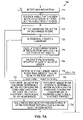
- FIGS. 7A–7B show a flow chart that illustrates an example of a method 700 of determining the positions of the handles in 3D space after the handles have been moved in accordance with the present invention.
- Method 700 can be executed by computer 100 .
- method 700 begins at step 714 by detecting if any user interaction has occurred, e.g., if any handles have been moved to a new position.
- FIGS. 8A–8C show views that illustrate an example of the movement of a handle in accordance with the present invention.
- a triangle 810 includes handles 1 , 2 , and 3 , and constraints L 12 , L 13 , and L 23 .
- handle 1 has been moved to a new position which, in turn, compresses constraint L 12 and stretches constraint L 13 .
- the length of constraint L 23 did not change.
- step 716 for each handle that has been moved by the user, such as handle 1 in FIG. 8A , method 700 sets a handle weight of the handle to zero.
- the user can also designate (lock) other handles to have a weight of zero.
- other weights such as 0.5, can also be assigned to a handle depending on the desired movement of the creature.
- step 720 Each handle has a current position and a summed motion vector, and in step 720 method 700 sets the summed motion vector of each handle to zero. After this, method 700 moves to step 722 to automatically select a constraint, and then to step 724 to calculate the current length of the constraint based on the current positions of the handles. (As described in greater detail below, method 700 iteratively determines values for each constraint, and can use any method of selecting constraints that allows each constraint to be processed.)
- Method 700 next moves to step 726 to determine the difference between the current and rest lengths of the constraint. Following this, method 700 moves to step 730 to determine if the current length of the constraint is less than, greater than, or equal to the rest length of the constraint.
- step 732 for a first handle of the constraint, a calculated motion vector is determined along the constraint away from the constraint with a magnitude (length) equal to 1 ⁇ 2 the difference between the current length and the rest length.
- step 734 for a first handle of the constraint, a calculated motion vector is determined along the constraint towards the constraint with a magnitude (length) equal to 1 ⁇ 2 the difference between the current length and the rest length.
- Method 700 moves from step 732 or 734 to step 736 to scale the calculated motion vector by the length weight of the constraint. (Method 700 multiplies the length weight of the constraint times the calculated motion vector of the handle.) Following this, method 700 moves to step 740 to add the calculated and scaled motion vector to the summed motion vector of the first handle. After this, method 700 moves to step 742 where the calculated and scaled motion vector is reversed and added to the summed motion vector of the second handle of the constraint.
- handle 1 when constraint L 12 is evaluated, handle 1 receives a calculated motion vector MV 1 , while handle 2 receives a reversed calculated motion vector MV 2 .
- Motion vectors MV 1 and MV 2 point away from each other along the line of the current constraint.
- the magnitudes (lengths) of vectors MV 1 and MV 2 are each equal to one-half of the difference between the current length and the rest length of constraint L 12 .
- handle 1 receives a calculated motion vector MV 3
- handle 3 receives a reversed calculated motion vector MV 4
- Motion vectors MV 3 and MV 4 point towards each other along the line of constraint L 13 .
- the magnitudes of vectors MV 3 and MV 4 are each equal to one-half of the difference between the current length and the rest length of constraint L 13 .
- handles 2 and 3 which are at opposite ends of constraint L 23 , receive no additional motion vectors when constraint L 23 is evaluated.
- FIG. 9 shows a graph that illustrates an example of the summation of a number of calculated motion vectors in accordance with the present invention.
- a summed motion vector A+B+C+D can be graphically determined by forming a vector from the origin of vector A to the end of the last calculated motion vector D.
- handle 1 is the only handle to have two calculated motion vectors, vectors MV 1 and MV 3 .
- the summed motion vector is equal to the sum of calculated and scaled motion vectors MV 1 and MV 3 .
- FIG. 9 shows only a two-dimensional representation
- the calculated and scaled motion vectors can be summed in 3D space in the same way.
- the summed motion vector represents the sum of all of the calculated and scaled motion vectors that have been added to the handle.
- method 700 moves to step 744 to determine if all of the constraints have been processed. Method 700 also moves to step 744 from step 730 when the current and rest lengths are equal. When more constraints remain to be evaluated, method 700 returns to step 722 to select another constraint.
- step 746 for each handle, method 700 multiplies the handle weight of the handle times the summed motion vector of the handle to determine a final motion vector.
- handle weight of the handle For each handle, handles that have been moved by the user have a handle weight of 0.0 which, in turn, zeros out the summed motion vector and prevents these handles from being moved.
- the summed motion vector for handle 1 is multiplied times zero. As a result, handle 1 has a summed motion vector with a magnitude of zero.
- method 700 moves to step 750 to determine new positions for each handle based on the current position of the handle and the final motion vector of the handle.
- method 700 moves to step 752 to determine if each constraint is equal to its original rest length (within a predetermined tolerance). If each constraint is not equal to its original rest length, method 700 moves to step 754 to determine if the process has been iterated a predetermined number of times. (Step 752 is optional, allowing the loop to end early when the constraint lengths have returned to their original rest lengths within the tolerance.) If the process has not been iterated a predetermined number of times, method 700 moves to step 720 to again set the summed motion vector of each handle to zero.
- step 756 shows the final results once the constraints have returned to their original length.
Abstract
Description
Claims (24)
Priority Applications (1)
| Application Number | Priority Date | Filing Date | Title |
|---|---|---|---|
| US10/338,416 US7202869B2 (en) | 2003-01-07 | 2003-01-07 | System and method of creating and animating a computer-generated image of a creature |
Applications Claiming Priority (1)
| Application Number | Priority Date | Filing Date | Title |
|---|---|---|---|
| US10/338,416 US7202869B2 (en) | 2003-01-07 | 2003-01-07 | System and method of creating and animating a computer-generated image of a creature |
Publications (2)
| Publication Number | Publication Date |
|---|---|
| US20060033740A1 US20060033740A1 (en) | 2006-02-16 |
| US7202869B2 true US7202869B2 (en) | 2007-04-10 |
Family
ID=35799542
Family Applications (1)
| Application Number | Title | Priority Date | Filing Date |
|---|---|---|---|
| US10/338,416 Expired - Lifetime US7202869B2 (en) | 2003-01-07 | 2003-01-07 | System and method of creating and animating a computer-generated image of a creature |
Country Status (1)
| Country | Link |
|---|---|
| US (1) | US7202869B2 (en) |
Cited By (11)
| Publication number | Priority date | Publication date | Assignee | Title |
|---|---|---|---|---|
| US20080012847A1 (en) * | 2006-07-11 | 2008-01-17 | Lucasfilm Entertainment Company Ltd. | Creating Character for Animation |
| US20090295793A1 (en) * | 2008-05-29 | 2009-12-03 | Taylor Robert R | Method and system for 3D surface deformation fitting |
| US7800618B1 (en) * | 2003-04-30 | 2010-09-21 | Apple Inc. | Method and apparatus for providing an animated representation of a reorder operation |
| US20110157306A1 (en) * | 2009-12-29 | 2011-06-30 | Industrial Technology Research Institute | Animation Generation Systems And Methods |
| US20110246960A1 (en) * | 2009-07-25 | 2011-10-06 | Irina Kleingon | Methods for software mass production |
| US20110285622A1 (en) * | 2010-05-20 | 2011-11-24 | Samsung Electronics Co., Ltd. | Rendition of 3d content on a handheld device |
| US8358311B1 (en) | 2007-10-23 | 2013-01-22 | Pixar | Interpolation between model poses using inverse kinematics |
| US8379028B1 (en) * | 2009-04-30 | 2013-02-19 | Pixar | Rigweb |
| US8456476B1 (en) * | 2008-12-24 | 2013-06-04 | Lucasfilm Entertainment Company Ltd. | Predicting constraint enforcement in online applications |
| US8704828B1 (en) | 2007-10-23 | 2014-04-22 | Pixar | Inverse kinematic melting for posing models |
| US10403404B2 (en) * | 2011-01-18 | 2019-09-03 | Disney Enterprises, Inc. | Physical face cloning |
Citations (15)
| Publication number | Priority date | Publication date | Assignee | Title |
|---|---|---|---|---|
| US4600919A (en) * | 1982-08-03 | 1986-07-15 | New York Institute Of Technology | Three dimensional animation |
| US5883638A (en) * | 1995-12-01 | 1999-03-16 | Lucas Digital, Ltd. | Method and apparatus for creating lifelike digital representations of computer animated objects by providing corrective enveloping |
| US6025852A (en) * | 1996-05-24 | 2000-02-15 | Zhao; Jianmin | Manipulation of graphic structures |
| US6191798B1 (en) * | 1997-03-31 | 2001-02-20 | Katrix, Inc. | Limb coordination system for interactive computer animation of articulated characters |
| US6317132B1 (en) * | 1994-08-02 | 2001-11-13 | New York University | Computer animation method for creating computer generated animated characters |
| US6400368B1 (en) * | 1997-03-20 | 2002-06-04 | Avid Technology, Inc. | System and method for constructing and using generalized skeletons for animation models |
| US6552729B1 (en) * | 1999-01-08 | 2003-04-22 | California Institute Of Technology | Automatic generation of animation of synthetic characters |
| US20030085900A1 (en) * | 2001-10-17 | 2003-05-08 | Michael Isner | Manipulation of motion data in an animation editing system |
| US20040021660A1 (en) * | 2002-08-02 | 2004-02-05 | Victor Ng-Thow-Hing | Anthropometry-based skeleton fitting |
| US6738065B1 (en) * | 1999-08-10 | 2004-05-18 | Oshri Even-Zohar | Customizable animation system |
| US6798416B2 (en) * | 2002-07-17 | 2004-09-28 | Kaydara, Inc. | Generating animation data using multiple interpolation procedures |
| US20040257368A1 (en) * | 2003-05-14 | 2004-12-23 | Pixar | Rig baking |
| US20040263518A1 (en) * | 2003-05-14 | 2004-12-30 | Pixar | Defrobulated angles for character joint representation |
| US20050007370A1 (en) * | 2003-05-14 | 2005-01-13 | Pixar | Integrated object squash and stretch method and apparatus |
| US20050253846A1 (en) * | 2004-05-14 | 2005-11-17 | Pixar | Patch picking methods and apparatus |
Family Cites Families (2)
| Publication number | Priority date | Publication date | Assignee | Title |
|---|---|---|---|---|
| US5458111A (en) * | 1994-09-06 | 1995-10-17 | William C. Bond | Computed tomographic colonoscopy |
| US5611025A (en) * | 1994-11-23 | 1997-03-11 | General Electric Company | Virtual internal cavity inspection system |
-
2003
- 2003-01-07 US US10/338,416 patent/US7202869B2/en not_active Expired - Lifetime
Patent Citations (18)
| Publication number | Priority date | Publication date | Assignee | Title |
|---|---|---|---|---|
| US4600919B1 (en) * | 1982-08-03 | 1992-09-15 | New York Inst Techn | |
| US4600919A (en) * | 1982-08-03 | 1986-07-15 | New York Institute Of Technology | Three dimensional animation |
| US6317132B1 (en) * | 1994-08-02 | 2001-11-13 | New York University | Computer animation method for creating computer generated animated characters |
| US5883638A (en) * | 1995-12-01 | 1999-03-16 | Lucas Digital, Ltd. | Method and apparatus for creating lifelike digital representations of computer animated objects by providing corrective enveloping |
| US6025852A (en) * | 1996-05-24 | 2000-02-15 | Zhao; Jianmin | Manipulation of graphic structures |
| US6400368B1 (en) * | 1997-03-20 | 2002-06-04 | Avid Technology, Inc. | System and method for constructing and using generalized skeletons for animation models |
| US6191798B1 (en) * | 1997-03-31 | 2001-02-20 | Katrix, Inc. | Limb coordination system for interactive computer animation of articulated characters |
| US6552729B1 (en) * | 1999-01-08 | 2003-04-22 | California Institute Of Technology | Automatic generation of animation of synthetic characters |
| US6738065B1 (en) * | 1999-08-10 | 2004-05-18 | Oshri Even-Zohar | Customizable animation system |
| US20030085900A1 (en) * | 2001-10-17 | 2003-05-08 | Michael Isner | Manipulation of motion data in an animation editing system |
| US20050041030A1 (en) * | 2001-10-17 | 2005-02-24 | Michael Isner | Manipulation of motion data in an animation editing system |
| US6798416B2 (en) * | 2002-07-17 | 2004-09-28 | Kaydara, Inc. | Generating animation data using multiple interpolation procedures |
| US20040021660A1 (en) * | 2002-08-02 | 2004-02-05 | Victor Ng-Thow-Hing | Anthropometry-based skeleton fitting |
| US20040257368A1 (en) * | 2003-05-14 | 2004-12-23 | Pixar | Rig baking |
| US20040263518A1 (en) * | 2003-05-14 | 2004-12-30 | Pixar | Defrobulated angles for character joint representation |
| US20050007370A1 (en) * | 2003-05-14 | 2005-01-13 | Pixar | Integrated object squash and stretch method and apparatus |
| US20050030310A1 (en) * | 2003-05-14 | 2005-02-10 | Pixar | Integrated object bend, squash and stretch method and apparatus |
| US20050253846A1 (en) * | 2004-05-14 | 2005-11-17 | Pixar | Patch picking methods and apparatus |
Non-Patent Citations (9)
| Title |
|---|
| Anderson, Frank C., "Static and Dynamic Optimization Solutions for Gait are Practically Equivalent",Journal of Biomechanics, 2001, vol. 34. pp. 153-161. * |
| Andrew Witkin, Michael Gleicher and William Welch, "In teractive Dynamics", Computer Graphics, V.24(2), Proceedings of the 1990 Symposium on the 3-D Interactive Graphics, Mar. 1990, pp. 11-21. |
| Chadwick et al., "Layered Construction for Deformable Animated Characters", ACM SIGGRAPH 89, Computer Graphics, vol. 23, No. 3, Jul. 1989. * |
| Grassia. F. Sebastian, "Practical parameterization of Rotations Using the Exponential Map", Journal of Graphics Tools, vol. 3, No. 3, 1998, pp. 29-48, A.K. Peters Ltd. * |
| Maciel, Anderson, et al. "Anatomy-based Joint Models for Virtual Humans Skeletons", In Proceedings of Computer Animation (2002), pp. 220-224. * |
| Michael L. Gleicher, "A Differential Approach to Graphical Interaction", Thesis Committee, School of Computer Science, Carnegie Mellon University, Nov. 18, 1994, pp. 1-250, Chapters 1, 6, 7, 8 & 9 most relevant. |
| Witkin et al., "Fast Animation and Control of Nonrigid Structures", ACM SIGGRAPH 90, Computer Graphics, vol. 24, No. 4, Aug. 1990, pp. 243-252. * |
| Witkin et al., "Spacetime Constraints", ACM SIGGRAPH 88, Computer Graphics, vol. 22, No. 4, Aug. 1988, pp. 159-168. * |
| Zhao et al., "Inverse Kinematics Positioning Using Nonlinear Programming for Highly Articulated Figures", ACM Transactions on Graphics, vol. 13, No. 4, Oct. 1994, pp. 313-336. * |
Cited By (16)
| Publication number | Priority date | Publication date | Assignee | Title |
|---|---|---|---|---|
| US7800618B1 (en) * | 2003-04-30 | 2010-09-21 | Apple Inc. | Method and apparatus for providing an animated representation of a reorder operation |
| US8477140B2 (en) | 2006-07-11 | 2013-07-02 | Lucasfilm Entertainment Company Ltd. | Creating character for animation |
| US20080012847A1 (en) * | 2006-07-11 | 2008-01-17 | Lucasfilm Entertainment Company Ltd. | Creating Character for Animation |
| US8704828B1 (en) | 2007-10-23 | 2014-04-22 | Pixar | Inverse kinematic melting for posing models |
| US8358311B1 (en) | 2007-10-23 | 2013-01-22 | Pixar | Interpolation between model poses using inverse kinematics |
| US20090295793A1 (en) * | 2008-05-29 | 2009-12-03 | Taylor Robert R | Method and system for 3D surface deformation fitting |
| US9129434B2 (en) | 2008-05-29 | 2015-09-08 | Robert R. Taylor | Method and system for 3D surface deformation fitting |
| US8456476B1 (en) * | 2008-12-24 | 2013-06-04 | Lucasfilm Entertainment Company Ltd. | Predicting constraint enforcement in online applications |
| US8379028B1 (en) * | 2009-04-30 | 2013-02-19 | Pixar | Rigweb |
| US20110246960A1 (en) * | 2009-07-25 | 2011-10-06 | Irina Kleingon | Methods for software mass production |
| US8966435B2 (en) * | 2009-07-25 | 2015-02-24 | Irina Kleingon | Methods for software mass production |
| US8462198B2 (en) | 2009-12-29 | 2013-06-11 | Industrial Technology Research Institute | Animation generation systems and methods |
| US20110157306A1 (en) * | 2009-12-29 | 2011-06-30 | Industrial Technology Research Institute | Animation Generation Systems And Methods |
| US20110285622A1 (en) * | 2010-05-20 | 2011-11-24 | Samsung Electronics Co., Ltd. | Rendition of 3d content on a handheld device |
| US8937592B2 (en) * | 2010-05-20 | 2015-01-20 | Samsung Electronics Co., Ltd. | Rendition of 3D content on a handheld device |
| US10403404B2 (en) * | 2011-01-18 | 2019-09-03 | Disney Enterprises, Inc. | Physical face cloning |
Also Published As
| Publication number | Publication date |
|---|---|
| US20060033740A1 (en) | 2006-02-16 |
Similar Documents
| Publication | Publication Date | Title |
|---|---|---|
| Müller et al. | Meshless deformations based on shape matching | |
| Mohr et al. | Building efficient, accurate character skins from examples | |
| US10297066B2 (en) | Animating a virtual object in a virtual world | |
| JP6762709B2 (en) | Computer implementation method for designing avatars with at least one garment | |
| Kenwright | Inverse kinematics–cyclic coordinate descent (CCD) | |
| CN113785330B (en) | Reinforcement learning for training characters using dissimilar target animation data | |
| Bender et al. | Position-based Methods for the Simulation of Solid Objects in Computer Graphics. | |
| Wang et al. | Example-based wrinkle synthesis for clothing animation | |
| Chuang et al. | Skeletonisation of three-dimensional object using generalized potential field | |
| Zurdo et al. | Animating wrinkles by example on non-skinned cloth | |
| US7202869B2 (en) | System and method of creating and animating a computer-generated image of a creature | |
| US11321895B2 (en) | Neural state machine digital character animation | |
| Xu et al. | Joint-aware manipulation of deformable models | |
| US20170221251A1 (en) | Animating a virtual object in a virtual world | |
| Redon et al. | Interactive and continuous collision detection for avatars in virtual environments | |
| Adams et al. | Meshless modeling of deformable shapes and their motion | |
| GB2546817A (en) | Animating a virtual object in a virtual world | |
| US8659606B1 (en) | Inversion of post-skinning features | |
| Kojekine et al. | Real-time 3D Deformations by Means of Compactly Supported Radial Basis Functions. | |
| Casti et al. | Skeleton based cage generation guided by harmonic fields | |
| Osher et al. | Deformable models: classic, topology-adaptive and generalized formulations | |
| Wade et al. | Fast, fully-automated generation of control skeletons for use in animation | |
| GB2512302A (en) | Animation of a virtual object | |
| Celikcan et al. | Example‐Based Retargeting of Human Motion to Arbitrary Mesh Models | |
| Bhatti et al. | Widget based automated rigging of bipedal character with custom manipulators |
Legal Events
| Date | Code | Title | Description |
|---|---|---|---|
| AS | Assignment |
Owner name: LUCAS DIGITAL LTD., LLC, CALIFORNIA Free format text: ASSIGNMENT OF ASSIGNORS INTEREST;ASSIGNOR:TOOLEY, JAMES ROBERT;REEL/FRAME:013648/0347 Effective date: 20030106 |
|
| AS | Assignment |
Owner name: LUCAS DIGITAL LTD., LLC, CALIFORNIA Free format text: ASSIGNMENT OF ASSIGNORS INTEREST;ASSIGNORS:PHILLIPS, CARY;POPRAVKA, NICOLAS;ANDERSON, JOHN;REEL/FRAME:014278/0202;SIGNING DATES FROM 20030522 TO 20030627 |
|
| AS | Assignment |
Owner name: LUCASFILM ENTERTAINMENT COMPANY LTD, CALIFORNIA Free format text: MERGER;ASSIGNOR:LUCAS DIGITAL LTD. LLC;REEL/FRAME:018338/0929 Effective date: 20040430 |
|
| STCF | Information on status: patent grant |
Free format text: PATENTED CASE |
|
| FPAY | Fee payment |
Year of fee payment: 4 |
|
| FEPP | Fee payment procedure |
Free format text: PAYOR NUMBER ASSIGNED (ORIGINAL EVENT CODE: ASPN); ENTITY STATUS OF PATENT OWNER: LARGE ENTITY |
|
| FEPP | Fee payment procedure |
Free format text: PAYOR NUMBER ASSIGNED (ORIGINAL EVENT CODE: ASPN); ENTITY STATUS OF PATENT OWNER: LARGE ENTITY Free format text: PAYER NUMBER DE-ASSIGNED (ORIGINAL EVENT CODE: RMPN); ENTITY STATUS OF PATENT OWNER: LARGE ENTITY |
|
| FPAY | Fee payment |
Year of fee payment: 8 |
|
| MAFP | Maintenance fee payment |
Free format text: PAYMENT OF MAINTENANCE FEE, 12TH YEAR, LARGE ENTITY (ORIGINAL EVENT CODE: M1553); ENTITY STATUS OF PATENT OWNER: LARGE ENTITY Year of fee payment: 12 |