US7190748B2 - Digital front-end for wireless communication system - Google Patents
Digital front-end for wireless communication system Download PDFInfo
- Publication number
- US7190748B2 US7190748B2 US10/144,445 US14444502A US7190748B2 US 7190748 B2 US7190748 B2 US 7190748B2 US 14444502 A US14444502 A US 14444502A US 7190748 B2 US7190748 B2 US 7190748B2
- Authority
- US
- United States
- Prior art keywords
- observations
- value
- gain
- largest
- receiver
- Prior art date
- Legal status (The legal status is an assumption and is not a legal conclusion. Google has not performed a legal analysis and makes no representation as to the accuracy of the status listed.)
- Active, expires
Links
Images


Classifications
-
- H—ELECTRICITY
- H04—ELECTRIC COMMUNICATION TECHNIQUE
- H04W—WIRELESS COMMUNICATION NETWORKS
- H04W28/00—Network traffic management; Network resource management
- H04W28/16—Central resource management; Negotiation of resources or communication parameters, e.g. negotiating bandwidth or QoS [Quality of Service]
- H04W28/18—Negotiating wireless communication parameters
-
- H—ELECTRICITY
- H04—ELECTRIC COMMUNICATION TECHNIQUE
- H04B—TRANSMISSION
- H04B7/00—Radio transmission systems, i.e. using radiation field
- H04B7/02—Diversity systems; Multi-antenna system, i.e. transmission or reception using multiple antennas
- H04B7/04—Diversity systems; Multi-antenna system, i.e. transmission or reception using multiple antennas using two or more spaced independent antennas
- H04B7/08—Diversity systems; Multi-antenna system, i.e. transmission or reception using multiple antennas using two or more spaced independent antennas at the receiving station
- H04B7/0837—Diversity systems; Multi-antenna system, i.e. transmission or reception using multiple antennas using two or more spaced independent antennas at the receiving station using pre-detection combining
- H04B7/0842—Weighted combining
- H04B7/0848—Joint weighting
-
- H—ELECTRICITY
- H04—ELECTRIC COMMUNICATION TECHNIQUE
- H04L—TRANSMISSION OF DIGITAL INFORMATION, e.g. TELEGRAPHIC COMMUNICATION
- H04L1/00—Arrangements for detecting or preventing errors in the information received
- H04L1/02—Arrangements for detecting or preventing errors in the information received by diversity reception
- H04L1/06—Arrangements for detecting or preventing errors in the information received by diversity reception using space diversity
-
- H—ELECTRICITY
- H04—ELECTRIC COMMUNICATION TECHNIQUE
- H04L—TRANSMISSION OF DIGITAL INFORMATION, e.g. TELEGRAPHIC COMMUNICATION
- H04L27/00—Modulated-carrier systems
- H04L27/26—Systems using multi-frequency codes
- H04L27/2601—Multicarrier modulation systems
- H04L27/2647—Arrangements specific to the receiver only
- H04L27/2655—Synchronisation arrangements
- H04L27/2657—Carrier synchronisation
-
- H—ELECTRICITY
- H04—ELECTRIC COMMUNICATION TECHNIQUE
- H04L—TRANSMISSION OF DIGITAL INFORMATION, e.g. TELEGRAPHIC COMMUNICATION
- H04L27/00—Modulated-carrier systems
- H04L27/26—Systems using multi-frequency codes
- H04L27/2601—Multicarrier modulation systems
- H04L27/2647—Arrangements specific to the receiver only
- H04L27/2655—Synchronisation arrangements
- H04L27/2662—Symbol synchronisation
-
- H—ELECTRICITY
- H04—ELECTRIC COMMUNICATION TECHNIQUE
- H04L—TRANSMISSION OF DIGITAL INFORMATION, e.g. TELEGRAPHIC COMMUNICATION
- H04L27/00—Modulated-carrier systems
- H04L27/26—Systems using multi-frequency codes
- H04L27/2601—Multicarrier modulation systems
- H04L27/2647—Arrangements specific to the receiver only
- H04L27/2655—Synchronisation arrangements
- H04L27/2668—Details of algorithms
- H04L27/2673—Details of algorithms characterised by synchronisation parameters
- H04L27/2675—Pilot or known symbols
-
- H—ELECTRICITY
- H04—ELECTRIC COMMUNICATION TECHNIQUE
- H04B—TRANSMISSION
- H04B7/00—Radio transmission systems, i.e. using radiation field
- H04B7/02—Diversity systems; Multi-antenna system, i.e. transmission or reception using multiple antennas
- H04B7/04—Diversity systems; Multi-antenna system, i.e. transmission or reception using multiple antennas using two or more spaced independent antennas
- H04B7/08—Diversity systems; Multi-antenna system, i.e. transmission or reception using multiple antennas using two or more spaced independent antennas at the receiving station
- H04B7/0837—Diversity systems; Multi-antenna system, i.e. transmission or reception using multiple antennas using two or more spaced independent antennas at the receiving station using pre-detection combining
- H04B7/0842—Weighted combining
- H04B7/0848—Joint weighting
- H04B7/0854—Joint weighting using error minimizing algorithms, e.g. minimum mean squared error [MMSE], "cross-correlation" or matrix inversion
-
- H—ELECTRICITY
- H04—ELECTRIC COMMUNICATION TECHNIQUE
- H04B—TRANSMISSION
- H04B7/00—Radio transmission systems, i.e. using radiation field
- H04B7/02—Diversity systems; Multi-antenna system, i.e. transmission or reception using multiple antennas
- H04B7/04—Diversity systems; Multi-antenna system, i.e. transmission or reception using multiple antennas using two or more spaced independent antennas
- H04B7/08—Diversity systems; Multi-antenna system, i.e. transmission or reception using multiple antennas using two or more spaced independent antennas at the receiving station
- H04B7/0837—Diversity systems; Multi-antenna system, i.e. transmission or reception using multiple antennas using two or more spaced independent antennas at the receiving station using pre-detection combining
- H04B7/0842—Weighted combining
- H04B7/0848—Joint weighting
- H04B7/0857—Joint weighting using maximum ratio combining techniques, e.g. signal-to- interference ratio [SIR], received signal strenght indication [RSS]
-
- H—ELECTRICITY
- H04—ELECTRIC COMMUNICATION TECHNIQUE
- H04W—WIRELESS COMMUNICATION NETWORKS
- H04W56/00—Synchronisation arrangements
-
- H—ELECTRICITY
- H04—ELECTRIC COMMUNICATION TECHNIQUE
- H04W—WIRELESS COMMUNICATION NETWORKS
- H04W84/00—Network topologies
- H04W84/02—Hierarchically pre-organised networks, e.g. paging networks, cellular networks, WLAN [Wireless Local Area Network] or WLL [Wireless Local Loop]
- H04W84/10—Small scale networks; Flat hierarchical networks
- H04W84/12—WLAN [Wireless Local Area Networks]
Definitions
- the invention relates to wireless communication and, more particularly, to techniques for digital acquisition of wireless signals.
- Wireless communication involves transmission of encoded information on a modulated radio frequency (RF) carrier signal.
- a wireless receiver includes an RF antenna that receives a wireless signal, and a demodulator that converts the RF signal to baseband.
- the wireless receiver may include a digital “front-end” that handles a variety of signal acquisition functions. For example, the digital front-end may perform signal detection, frame synchronization, carrier frequency offset (CFO) estimation and correction, and gain control.
- CFO carrier frequency offset
- the gain control function involves selection of a gain for amplification of the incoming wireless signal to increase signal amplitude but avoid saturation.
- Signal detection involves detecting the arrival of a transmitted wireless signal.
- Frame synchronization involves identification of the start of a transmitted symbol within the signal.
- the CFO estimation and correction function estimates the carrier frequency difference between the transmitter and receiver, and compensates for the difference in the receiver.
- the invention is directed to a digital front-end for a wireless communication system.
- a digital front-end in accordance with the invention, may incorporate gain control, signal detection, frame synchronization and carrier frequency offset (CFO) estimation and correction features configured for use with wireless communication systems having one or more receive antennas.
- the digital front-end may be especially useful when combined with multiple receive antennas in a receive diversity arrangement.
- the digital front-end may be applied to any wireless communication system in which transmitted signals carry a repeated signal pattern.
- the digital front-end may be especially useful in multi-carrier wireless systems, such as orthogonal frequency division multiplexing (OFDM) systems.
- OFDM orthogonal frequency division multiplexing
- An example of a repeated signal pattern is the preamble of a signal transmitted according to the IEEE 802.11a wireless local area network (WLAN) standard.
- the signal detection, frame synchronization, and CFO estimation techniques can make use of signals received from multiple antenna paths to provide enhanced performance.
- the gain control feature may be configured to adjust the gain in steps. During the preamble period, for example, the amplitude of the received signal may vary due to gain control.
- the frame synchronization technique may be effective even when the signal amplitude varies under such conditions. In particular, the frame synchronization technique may operate as a function of gain control, handling the input signal differently before and after gain adjustment.
- the invention provides a method comprising receiving observations of a wireless signal via multiple antennas, measuring power levels of the observations, identifying a largest power level among the measured power levels, selecting an amplifier gain based on the largest measured power level, and applying the amplifier gain to each of the observations.
- the invention provides a method comprising receiving one or more observations of a wireless signal via one or more antennas, measuring a power level of each of the observations, generating a correlation of the measured power level, and indicating a signal detection based on the correlation and a delayed version of the measured power level.
- the invention provides a method comprising receiving one or more observations of a wireless signal via one or more antennas, calculating an absolute squared value of an inner product between a unit vector of observation samples from the antennas and a time delayed unit vector of observation samples from the antennas, and identifying a largest absolute squared inner product value among the calculated absolute squared inner product values.
- the invention provides a method comprising receiving one or more observations of a wireless signal via one or more antennas, generating a correlation of the observations for each of the antennas, averaging the correlations over all of the antennas, and estimating a carrier frequency offset based on the angle of the averaged correlations.
- the invention provides wireless receivers capable of implementing the various methods.
- the invention may provide one or more advantages.
- the invention may take advantage of the presence of a repeated signal pattern in a wireless signal and receive diversity to promote enhanced signal detection, frame synchronization and CFO correction performance, even as signal gain varies.
- the invention can provide reduced incidents of false signal detection, more accurate frame synchronization, and more effective CFO correction.
- FIG. 1 is a block diagram illustrating a wireless communication network.
- FIG. 2 is a block diagram illustrating a wireless communication device useful in the network of FIG. 1 .
- FIG. 3 is a diagram of an OFDM frame transmitted according to the IEEE 802.11a standard.
- FIG. 4 is another diagram of an OFDM frame, illustrating the start and end of a transmitted frame.
- FIG. 5 is a block diagram illustrating radio and modem circuitry within a wireless communication device.
- FIG. 6 is a block diagram of a digital front-end for use with a wireless communication device.
- FIG. 7 is a diagram of a gain control unit forming part of the digital front-end of FIG. 6 .
- FIG. 8 is a diagram of a signal detection unit forming part of the digital front-end of FIG. 6 .
- FIG. 9 is a diagram of a frame synchronization unit forming part of the digital front-end of FIG. 6 .
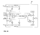
- FIG. 10 is a diagram of a carrier frequency offset (CFO) estimation and correction circuit forming part of the digital front-end of FIG. 6 .
- CFO carrier frequency offset
- FIG. 11 is a flow diagram illustrating a gain control technique.
- FIG. 12 is a flow diagram illustrating a signal detection technique.
- FIG. 13 is a flow diagram illustrating a frame synchronization technique.
- FIG. 14 is a flow diagram illustrating a CFO estimation and correction technique.
- FIG. 1 is a block diagram illustrating a wireless communication network 10 .
- Wireless communication network 10 may incorporate multiple receive antennas for receive diversity in accordance with some embodiments of the invention.
- Receive diversity may be effective in enhancing gain control, signal detection, frame synchronization, and carrier frequency offset (CFO) estimation and correction features associated with a digital front-end provided in wireless communication devices in network 10 .
- a digital front-end constructed in accordance with the invention may be especially useful in multi-carrier wireless systems, such as orthogonal frequency division multiplexing (OFDM) systems, or other systems in which each frame carries a repeated signal pattern.
- OFDM orthogonal frequency division multiplexing
- An example of a repeated signal pattern is the preamble of a signal transmitted according to the IEEE 802.11a wireless local area network (WLAN) standard.
- WLAN wireless local area network
- wireless communication network 10 may include one or more wireless access points 12 coupled to a wired network 14 , e.g., via an Ethernet connection.
- Wireless access point 12 permits wireless communication between wired network 14 and one or more wireless communication devices 16 A– 16 N (hereinafter 16 ).
- Each wireless communication device 16 as well as wireless access point 12 , may include two or more antennas that provide multiple receive paths for receive diversity, as will be described in further detail herein.
- Wireless access point 12 may integrate a hub, switch or router to serve multiple wireless communication devices 16 .
- Wireless communication network 10 may be used to communicate data, voice, video and the like between devices 16 and network 14 according to a variety of different wireless transmission standards, e.g., based on a multi-carrier communication technique such as OFDM.
- OFDM multi-carrier communication technique
- FIG. 2 is a block diagram illustrating a wireless communication device 16 in further detail.
- wireless communication device 16 may include one or more radio frequency (RF) antennas 18 A, 18 B (hereinafter 18 ), a transmit antenna 20 , a radio 22 , a modem 24 , a media access controller (MAC) 26 and host processor 28 .
- RF radio frequency
- wireless communication device 16 may include at least two RF antennas 18 A, 18 B.
- Radio 22 and modem 24 function together as a wireless receiver.
- Wireless communication device 16 may take the form of a variety of wireless equipment, such as computers, personal computer cards, e.g., PCI or PCMCIA cards, personal digital assistants (PDAs), network audio or video appliances, and the like.
- PDAs personal digital assistants
- Radio 22 may include circuitry for upconverting transmitted signals to RF, and downconverting RF signals to baseband. In this sense, radio 22 may integrate both transmit and receive circuitry within a single transceiver component. In some cases, however, transmit and receive circuitry may be formed by separate transmitter and receiver components. For purposes of illustration, discussion herein will be generally limited to the receiver and demodulation aspects of radio 22 and modem 24 .
- Modem 24 encodes information in a baseband signal for upconversion to the RF band by radio 22 and transmission via a transmit antenna 20 .
- modem 24 decodes information from RF signals received via antennas 18 and downconverted to baseband by radio 22 .
- the RF signals received by multiple antennas 18 A, 18 B may be demodulated to produce symbol observations that can be combined to form a combined symbol observation for decoding by modem 24 .
- a digital front-end within modem 24 may provide gain control, signal detection, frame synchronization and CFO estimation and correction functions for signals received by wireless communication device 16 via antennas 18 .
- MAC 26 interacts with host processor 28 to facilitate communication between modem 24 and a host wireless communication device 16 , e.g., a computer, PDA or the like.
- host processor 28 may be a CPU within a computer or some other device.
- Radio 22 , modem 24 and MAC 26 may be integrated on a common integrated circuit chip, or realized by discrete components.
- Wireless communication network 10 ( FIG. 1 ) and wireless communication device 16 ( FIG. 2 ) may conform to a wireless networking standard, such as the IEEE 802.11a standard.
- the IEEE 802.11a standard specifies a format for the radio frequency (RF) transmission of orthogonal frequency division multiplexed (OFDM) data.
- RF radio frequency
- OFDM orthogonal frequency division multiplexed
- Incorporation of multiple antennas 18 for receive diversity in an OFDM wireless communication system can enhance the performance of gain control, signal detection, frame synchronization and CFO estimation and correction features, particularly when the received signals carry a repeating signal pattern, such as the preamble signal provided by the IEEE 802.11a wireless local area network (WLAN) standard.
- WLAN wireless local area network
- FIG. 3 is a diagram of an OFDM frame, or “packet,” transmitted according to the IEEE 802.11a standard.
- the OFDM frame includes a physical layer convergence procedure (PLCP) preamble 30 that contains a short preamble 32 , a guard interval 34 and a long preamble 36 .
- the signal structure specified by the IEEE 802.11a standard includes a repeating signal pattern in preamble 30 .
- a signal field 38 follows long preamble 36 , and contains a symbol encoding rate and length information for the OFDM frame.
- Service and data fields (SERVICE/DATA), identified together with reference numeral 40 in FIG. 3 , follow signal field 38 .
- the data field contains the data “payload” for the OFDM frame and follows the service field.
- Short preamble 32 carries a repetition of 10 short symbols, each of which is 16 samples in length.
- Long preamble 36 carries two repeated symbols that are each 64 samples in length.
- long preamble 36 is preceded by guard interval 34 , which contains a cycle prefix that is 32 samples in length.
- the cycle prefix is a replica of the last 32 samples of a long symbol from long preamble 36 .
- the techniques described herein for gain control, signal detection, frame synchronization make use of the repeating characteristics of short preamble 32 .
- the CFO estimation and correction technique described herein is applied to both short preamble 32 and long preamble 36 .
- the techniques described herein are capable of application to a variety of signals involving a repeating signal pattern, and are not necessarily limited to an 802.11a system, nor even an OFDM system.
- FIG. 4 is another diagram of an OFDM frame as shown in FIG. 3 , illustrating the start and end of a transmitted frame.
- Burst communications are characterized by the transmission and reception of data packets or frames separated by a null signal period. Accordingly, as shown in FIG. 4 , each OFDM frame is transmitted as a burst and therefore is typically preceded and followed by null signal periods 42 , 44 , respectively.
- null signal periods 42 , 44 antennas 18 receives a relatively low power signal characterized by channel noise.
- signal detection techniques typically rely on identification of a transition point between the null signal period 42 and the onset of short preamble 32 .
- FIG. 5 is a block diagram illustrating radio and modem circuitry within a wireless communication device.
- radio 22 may include a downconverter 46 that receives an RF signal via antenna 18 .
- Downconverter 46 mixes the received RF signal with a signal received from a frequency synthesizer 48 to convert the RF signal down to a baseband frequency.
- Radio 22 also may include a low noise amplifier and other signal conditioning circuitry (not shown in FIG. 5 ).
- Modem 24 may include an analog-to-digital converter (ADC) 50 that produces a digital representation of the baseband signal.
- ADC 50 may include an amplifier (not shown in FIG. 5 ) that applies a gain to the analog baseband signal prior to conversion to a digital signal.
- a digital front-end (DFE) 52 receives the digital signal from ADC 50 and performs a number of functions, including gain control, signal detection, frame synchronization and CFO estimation and correction.
- a fast Fourier transform (FFT) unit 54 receives the digital signal from ADC 50 and produces FFT outputs to demodulate the signal.
- a decoder 56 decodes the FFT outputs to recover the information carried by the received signal. In particular, decoder 56 decodes the information carried by a given tone and produces a stream of serial data for transmission to host processor 28 via MAC 26 ( FIG. 2 ).
- FFT fast Fourier transform
- DFE 52 applies control signals to ADC 50 to control the gain of the amplifier associated with or preceding the ADC.
- DFE 52 may apply signal detection and frame synchronization signals to the FFT unit 54 to aid in acquisition of the digital signal.
- DFE 52 also may apply control signals to a CFO correction unit (not shown in FIG. 5 ) to provide CFO compensation of the digital signal.
- Modem 24 also may include a channel estimator (not shown) that estimates a complex gain A for a particular frequency bin that corresponds to the transmitted signal information.
- FIG. 5 shows a single antenna path and associated modem circuitry. However, the structure of FIG. 5 may be readily applied to a multiple antenna arrangement providing receive diversity, as will be described.
- FIG. 6 is a block diagram of a digital front-end 52 for use with a wireless communication device.
- amplifiers 58 A, 58 B amplify baseband signals received from radio 22 with a controllable gain.
- the signals amplified by amplifiers 58 A, 58 B are received by different antennas 18 A, 18 B, providing receive diversity.
- ADCs 50 A, 50 B convert the amplified baseband signals to digital representations.
- DFE 52 includes gain control unit 60 , signal detection unit 62 and frame synchronization unit 64 .
- DFE 52 may include CFO estimator unit 66 and CFO correction units 68 A, 68 B that compensate the digital signals produced by ADCs 50 A, 50 B, respectively.
- Gain control unit 60 detects the levels of the outputs from ADCs 50 A, 50 B, respectively, and generates a digital gain control signal.
- a digital-to-analog converter (DAC) 70 converts the gain control signal to an analog signal that is applied to amplifiers 58 A, 58 B to selectively control the gain applied to the incoming baseband signals.
- DAC digital-to-analog converter
- Signal detection unit 62 monitors the outputs of ADCs 50 A, 50 B to detect the arrival of a transmitted signal. In particular, signal detection unit 62 identifies the start of a signal, e.g., an OFDM frame, and generates a control signal indicating signal detection. Signal detection unit 62 applies the signal detection control signal to gain control unit 60 , triggering commencement of the gain control operation.
- a signal e.g., an OFDM frame
- Frame synchronization unit 64 detects the beginning of a transmitted symbol and generates a frame synchronization control signal that is applied to FFT unit 54 .
- FFT unit 54 controls an FFT sampling window associated with FFT sub-units 54 A, 54 B, which demodulate the signals for the first and second channels, respectively.
- frame synchronization unit 64 also may be responsive to gain control unit 60 . In particular, the operation of frame synchronization unit 64 may vary depending on the status of the gain applied to the incoming baseband signals.
- CFO estimator unit 66 monitors the signals applied to FFT units 54 A, 54 B to estimate the carrier frequency difference between the transmitter and receiver in each signal. Based on the estimated CFO, CFO estimator 66 generates a control signal that is applied to CFO correction units 68 A, 68 B. CFO correction units 68 A, 68 B correct the carrier frequency in the digital signals on an ongoing basis to compensate for the carrier frequency difference in the receiver and thereby enhance the accuracy of the symbols recovered from the signals.
- the gain control unit 60 , signal detection unit 62 , frame synchronization unit 64 , CFO estimation unit 66 , and CFO correction units 58 A, 58 B of DFE 52 will now be described in greater detail.
- Signal detection unit 62 , frame synchronization unit 64 , CFO estimation unit 66 , and CFO correction units 58 A, 58 B use signals from multiple antenna paths for improved performance.
- FIG. 7 is a diagram of gain control unit 60 .
- gain control unit 60 operates in such a way that the typical assumption of white channel noise used in receiver design need not be disturbed by the gain control.
- the arrival of the transmitted signal at the receiver is detected by signal detection unit 62 at the beginning of the short preamble and notified to gain control unit 60 to start the amplifier gain adjustment procedure.
- the gain of the amplifier is adjusted by gain control unit 60 so that the observed signal power can meet a certain target.
- gain adjustment is finished, the gain will be frozen until the end of the frame.
- the end of the gain update is notified to the frame synchronization unit 64 so that the input signal to frame synchronization unit 64 can be handled differently for the two time periods—before and after the gain adjustment—as described below.
- the assumption of the same noise power for different receive paths may result in a reduced complexity solution.
- the maximum ratio combiner (MRC) for the wireless communication e.g., OFDM
- MRC maximum ratio combiner
- SNR estimated signal-to-noise ratio
- a gain control unit 60 as described herein is designed to avoid disturbing, i.e., changing, the relative noise power between the different signal paths received by multiple antennas 18 .
- succeeding receiver blocks such as signal detection unit 62 , frame synchronization unit 64 , and CFO estimator 66 , can be designed under the assumption of identical noise power for all of the different signal paths.
- gain control unit 60 obviates the need to estimate noise in multiple paths. For example, denoting the sampled and quantized received signal for the i-th signal path observed at j-th clock by r i,j , the signal power can be estimated by:
- N the number of samples used to estimate the signal power.
- N should be at least 16 to obtain a reliable power estimate.
- the input sample can be quantized to the power of 2 value, as shown in FIG. 7 , before being used in the power estimation.
- the gain of the amplifier for the i-th signal path can be represented by:
- the same gain can be used for each of the amplifiers 58 A, 58 B for different signal paths so that the relative noise powers between signal paths are not affected by the gain control.
- the signal path with the largest measured signal power is used to estimate the signal gain.
- the signal gain can be obtained by:
- multiple gain adjustments may be necessary to arrive at a desirable gain level.
- the initial gain is set to a high value at which the weakest signal the receiver can decode reliably is observed with a sufficient precision at the output of one of ADCs 50 A, 50 B.
- the strongest signal the receiver should decode successfully may saturate ADCs 50 A, 50 B or other circuits in the receiver signal path. If saturation occurs, the measured power for the signal will be smaller than the actual signal power. The gain update based on this measured power will result in a larger gain than the final gain at which the observed signal power is equal to RefPower.
- a solution to the saturation issue is to adjust the gain multiple times.
- gain control unit 60 may adjust the gain downward in a large step, ThLargeStep.
- the threshold value ThLargeSignal and the step value ThLargeStep may be programmable. After the gain is updated, the next power estimation for another round of gain adjustment should to be delayed until the signal has settled. If the estimated signal power is still larger than ThLargeSignal, gain control unit 60 may repeat the gain adjustment and power estimation. If the estimated power is smaller than a threshold value ThLargeSignal, the gain is updated as a final adjustment. In this approach, whether the receiver circuit is saturated by the input signal or not is determined by comparing the estimated power with this threshold value ThLargeSignal.
- FIG. 7 represents one possible implementation of a gain control unit 60 .
- Accumulation of the magnitude squared samples starts either when the arrival of the signal is detected by signal detection unit 62 , or after a finite delay from a previous gain update.
- a counter circuit counts the accumulated samples The counter circuit is reset to zero when accumulation starts.
- N the predetermined value
- the accumulation process is finished and the gain is updated based on the measured signal power.
- the counter value reaches N
- the counter is reset to zero and counts up until it reaches the value M, which corresponds to the delay required for the signal to be settled down after the gain update.
- gain control unit 60 If the estimated signal power is smaller than ThLargeSignal, as indicated by the adder, gain control unit 60 notifies frame synchronization unit 64 of the end of the gain update routine. If the estimate signal power is not smaller than ThLargeSignal, gain control unit 60 adjusts the gain in a large step, ThLargeStep, and the signal power estimation routine within gain control unit 60 is restarted for another gain update cycle. For example, as shown in the example of FIG. 7 , the sign operation on the output of the adder causes the output multiplexer to select the large step gain, ThLargeStep. The calculated gain, i.e., the maximum power level for the two paths, can be converted to a logarithmic value.
- the gain of the amplifier can be compared to the reference power level RefPower and adjusted in a dB-linear fashion.
- the power level RefPower may be programmable.
- Quantization blocks convert the respective input values to the nearest power of 2 value. In particular, the output of the quantization block is given by
- FIG. 8 is a diagram of an exemplary signal detection unit 62 .
- signals t 1 through t 10 are the identical short symbols.
- r k which can be a sampled and complex valued signal consisting of real and imaginary parts.
- N is the number of received samples in each short symbol ti
- P is an integer value between N and (10-1)N
- M is a positive integer
- D is a positive integer larger than or equal to 2N
- threshold is a positive value. This threshold value may be programmable.
- the numerator in expression (4) represents calculation of the signal power using the signal repetition property in the short preamble.
- the denominator is a delayed version of the signal power estimate.
- the numerator in expression (4) is simply a correlation of two signals, which is typically smaller than the power of the signal, the denominator.
- the numerator and denominator are the power estimates of the preamble signal and noise, respectively.
- the signal power is much larger than that of the noise. Consequently, the arrival of the preamble signal can be detected reliably.
- Existing methods for signal detection generally involve power measurement techniques or correlation-based techniques.
- the arrival of the packet can be detected by monitoring the power of the received signal. If there is a sudden jump in signal power, the packet arrival is flagged by the existing power management technique. If there is any chance that interference from neighboring channels is received, however, this existing power measurement-based signal detection technique may falsely detect the interference as the arrival of the intended signal.
- a signal detection method that makes use of equation (8) may perform comparably with a method that makes use of equation (4), as described herein. At the arrival of the short preamble signal, however, the left hand side of equation (4) results in a much larger value than that of equation (8). In this manner, a signal detection method that relies on equation (4) is superior in sensitivity and resistance to false detection.
- equation (8) Another potential drawback of equation (8) relative to equation (4) is observed when the transmitted packet ends.
- the numerator of equation (8) is the correlation output of the transmitted signal, whereas the denominator is the power estimate of the noise. Therefore, the result of equation (8) can be large at the end of the packet, resulting in a false signal detection.
- the performance of signal detection unit 62 can improve significantly.
- the above equations (4)–(7) can be extended to cover multiple receive antenna cases by summing the transmitted signal over multiple receive paths.
- the signal detect algorithm of equation (5) can be extended to:
- threshold 1 and threshold 2 may be programmable.
- the value 16 in the subscript of equation (4) is attributable to the preamble structure shown in FIGS. 3 and 4 . This value can be changed to accommodate a different preamble structure, as desired. If both parameters are set to non-zero values, the signal is detected only when the sum of the correlation is larger than both the delayed power estimate and some predetermined value. In this way, it is possible to prevent false detection due to noise input.
- FIG. 8 illustrates one possible implementation of signal detector 62 .
- the input samples can be quantized to the nearest power of 2 value to reduce hardware complexity.
- the use of observation samples from both paths improves the signal detection quality significantly, relative to the case in which only one receive signal is utilized.
- Some RF circuit structures or coupling may introduce narrowband interference at DC or the Nyquist frequency.
- the implementation of signal detection unit 62 in FIG. 8 can operate reliably under this noisy condition by using the threshold 1 term in equation (9).
- An explicit suppression of noise is also possible by applying a bandpass filter to the input signal of the signal detection unit 62 .
- the subcarriers at the band edge are not used to ease signal filtering.
- only sixteen subcarriers are transmitted during the short preamble period in which the signal detection unit 62 operates. Due to these unused subcarriers around the DC and band edge, applying a bandpass filter does not degrade the signal detection performance significantly.
- An example of one simple filter can be 1 ⁇ D 2 .
- FIG. 9 is a diagram of an exemplary frame synchronization unit 64 .
- frame synchronization unit 64 can be configured to search the largest inner product of two normalized signal vectors to locate the end of the short preamble.
- the first vector consists of 144 consecutive signal observation samples.
- the other vector a 16-sample delayed version of the first vector.
- the normalized (or unit) vector is obtained by dividing the vector by its magnitude.
- the number of samples, i.e., 144 and 16 are specific to this particular example for an IEEE 802.11a frame.
- the frame synchronization algorithm described herein can be used with a different set of sample numbers for different applications.
- the inner product of the two corresponding unit vectors will be equal to 1. If the two vectors are not the same, the inner product of their unit vectors will always be less than 1. In a multiple receive antenna case, the signal from each single path will preserve the repetition property. Building a large vector by stacking vectors obtained from each signal path, the inner product can still be used for frame synchronization purposes for multiple receive antennas. As the vector size increases, the peak location of the inner product will be more accurate. According to one embodiment, the end of the short preamble shown in FIG. 3 or 4 can be detected by:
- gain control unit 60 updates the signal gain applied by amplifiers 58 A, 58 B.
- a gain update in the middle of the short preamble does not preserve the repeating signal characteristic, which can result in performance degradation of the frame synchronization unit 64 .
- a frame synchronization unit 64 that is robust even during significant signal amplitude fluctuation can be achieved by using only the sign information for those samples observed before the settlement of the signal gain. That is, the x i,j defined as below is used in equation (10) in place of r i,j as follows:
- x i , j ⁇ Ref ⁇ ⁇ Mag ⁇ ( sign ⁇ ( Re ⁇ ( r i , j ) ) + - 1 ⁇ sign ⁇ ( Im ⁇ ( r i , j ) ) ) before ⁇ ⁇ the ⁇ ⁇ gain ⁇ ⁇ update ⁇ ⁇ is ⁇ ⁇ settled ⁇ ⁇ down ⁇ r i , j after ⁇ ⁇ the ⁇ ⁇ gain ⁇ ⁇ update ⁇ ⁇ is ⁇ ⁇ settled ⁇ ⁇ down ( 11 )
- RefMag is a predetermined positive value that serves as a reference magnitude.
- the inner product from equation (10) may result in a false peak even with the use of equation (11).
- Another method is to search the peak only when the calculated inner product is larger than a certain threshold value as implemented in FIG. 8 .
- the inner product according to equation (10) increases because of the arrival of this new repeated signal.
- the power of the oldest sample leaving the vector is smaller than the new incoming sample.
- the inner product of these newly formed unit vectors is smaller than that obtained for the previous vectors.
- large powered signals enter the vector while small powered signals leave the vector.
- the inner product will become progressively smaller.
- a unique peak in the inner product can be located at the end of the short preamble even when the repetition property has been compromised at the beginning.
- FIG. 9 shows an example implementation of a frame synchronization unit 64 .
- the maximum search of the ratio of equation (10) is conducted only when the ratio is larger than a certain threshold value, which may be programmable.
- the peak location of the ratio, which is at the end of the short preamble, is released when the maximum value is not updated for a prescribed period of time.
- a counter is used to measure this time period. The counter is reset to a zero value either when a new maximum value is found or when the ratio is smaller than the threshold.
- the ‘ext-bits’ blocks in FIG. 9 each represent the implementation of equation (11).
- the input sample is quantized to the nearest power of 2 value.
- frame synchronization unit 64 of FIG. 9 can be degraded by a correlated noise such as narrowband interference. For this reason, a bandpass filter as described above with respect to signal detection unit 62 can also be applied in frame synchronization unit 64 to suppress narrowband interferences at DC and Nyquist frequency.
- FIG. 10 is a diagram of combined carrier frequency offset (CFO) estimation and correction unit 66 , 68 .
- s i,j is the ideally demodulated sample with the perfectly matched carrier frequency
- ⁇ f c is the carrier frequency offset (CFO) between the transmitter and receiver
- T is the sampling period.
- the carrier frequency offset 2 ⁇ f c ⁇ T can be denoted as ⁇ w c .
- the typical transmitter and receiver derive their clocks from a single source respectively.
- demodulated signals from different antennas suffer from the same amount of carrier frequency offset relative to the transmitter frequency. Averaging the correlation over the different signal paths, this carrier frequency offset can be estimated by
- j is the time index corresponding to the end of the short preamble detected by the frame synchronization unit 64
- K is the number of samples used for CFO estimation determined such that at the time j ⁇ K+1–16, the received signal is settled down after application of gain control unit 60 to adjust signal gain.
- the CFO estimation (12) starts 16 samples after the gain control routine is settled down and ends at the end of the short preamble flagged by the frame synchronization unit 64 .
- CFO estimator unit 66 uses only those samples with a sufficient precision observed after the gain control is finished.
- CFO estimator unit 66 by using the long preamble, can have the same form as:
- the long preamble is also used for channel estimation in which any phase rotation is accounted for as part of the channel response.
- the phase error due to the residual CFO during the long preamble becomes part of the channel response after the channel estimation.
- FIG. 11 is a flow diagram illustrating a gain control technique.
- the gain control technique may be implemented within a gain control unit 60 as described herein.
- gain control unit 60 receives observations of a wireless signal via multiple antennas ( 70 ), thereby making use of receive diversity for purposes of gain control.
- Gain control unit 60 measures the signal power for each signal ( 72 ), and identifies the largest measured signal power ( 74 ) among the multiple observations.
- gain control unit 60 updates the gain by a large decrement ( 78 ), i.e., ThLargeStep.
- Gain control unit 60 applies the resulting gain to all of the wireless signal observations ( 80 ), i.e., the signals received on all of the multiple antennas.
- Gain control unit 60 then initiates another measurement and comparison cycle ( 70 , 72 , 74 , 76 ). If the largest measured signal power is less than the threshold ( 76 ), gain control unit 60 selects a gain based on the identified largest measured signal power ( 82 ), and applies the gain to all of the observations ( 84 ). This gain applied in step ( 84 ) serves as the final gain and is frozen for the remainder of the packet. For the next packet, gain control unit 60 restarts the measurement process.
- FIG. 12 is a flow diagram illustrating a signal detection technique, which may be implemented within signal detection unit 62 as described herein.
- signal detection unit 62 samples one or more wireless signals ( 88 ) received via an antenna 18 or multiple antennas. In general, sampling of multiple signals received via a receive diversity antenna arrangement will be desirable.
- signal detection unit 62 Upon measurement of the signal power of the wireless signal(s) ( 90 ), signal detection unit 62 calculates a correlation ( 92 ) as described previously, e.g., with respect to equations (4), (5), (6) and (5)′.
- Signal detection unit 62 compares the correlation to a delayed signal power measurement ( 94 ) of the wireless signal(s).
- the numerator in expression (4) represents calculation of the signal power using the signal repetition property in the short preamble, whereas the denominator is a delayed version of the signal power estimate.
- the comparison may produce a ratio.
- signal detection unit 62 determines whether a detection threshold has been exceeded ( 96 ). If so, signal detection unit 62 generates a control signal that indicates that a signal has been detected ( 98 ), and transmits the control signal to gain control unit 60 to activate the gain control routine ( 100 ). If not, signal detection unit 62 continues to monitor the incoming wireless signal observations to detect a signal.
- FIG. 13 is a flow diagram illustrating a frame synchronization technique, which may be implemented within a frame synchronization unit 64 as described herein.
- frame synchronization unit 64 receives wireless signals via multiple antennas ( 102 ), and generates observation samples ( 106 ).
- the observation samples represent samples within the short preamble symbol of the relevant packet.
- Frame synchronization unit 64 uses the observation samples to identify the beginning and end of the data portion of the packet. However, the manner in which frame synchronization unit 64 processes the observation samples varies according to the gain control routine.
- frame synchronization unit 64 calculates the absolute square of the inner product of a sample vector and a delayed vector ( 112 ). If the gain is not yet settled, however, frame synchronization unit 64 first converts the observation samples to a same-sign reference value ( 110 ), as described in equation (11) above, before calculating the inner product. In either case, frame synchronization unit 64 then identifies the largest absolute square inner product ( 114 ), i.e., the peak. If the result of the peak exceeds an applicable detection threshold ( 118 ), frame synchronization unit 64 indicates the end of the short preamble ( 120 ). If the result does not exceed the detection threshold, frame synchronization unit 64 returns to process additional samples and thereby identify the end of the short preamble.
- FIG. 14 is a flow diagram illustrating a CFO estimation and correction technique, which may be implemented with a CFO estimator unit 66 and CFO correction unit 68 as described herein.
- CFO estimator unit 66 receives wireless signals via multiple antennas ( 122 ). Upon generating observation samples for the wireless signals ( 124 ), CFO estimator unit 66 calculates a correlation between the observation samples and a delayed version of the observation samples ( 126 ). CFO estimator unit 66 then averages the correlations over all of the antennas ( 128 ), and estimates a CFO based on the angle of the averaged correlations ( 130 ). On this basis, CFO correction unit 68 applies a correction to each signal path that corrects the CFO ( 132 ).
- the various components described herein for gain control, signal detection, frame synchronization and carrier frequency offset estimation and correction may be formed by a variety of hardware components such as integrated logic circuitry, e.g., an Application Specific Integrated Circuit (ASIC), programmable logic devices, microprocessors, and the like. For size and complexity reasons, it may be desirable that the various components be formed together within a common hardware device such as an ASIC.
- ASIC Application Specific Integrated Circuit
Abstract
Description
where N is the number of samples used to estimate the signal power. For
In accordance with the invention, the same gain can be used for each of the
where x is an integer. A more accurate estimate of the signal power can be obtained by quantizing the input sample as:
where aiε{0,1} and Q is a non-zero integer. The simplest case will be for Q=1. When the input sample is quantized to the nearest power of 2 value (Q=1), the multipliers and squaring operators of
where N is the number of received samples in each short symbol ti, P is an integer value between N and (10-1)N, M is a positive integer, D is a positive integer larger than or equal to 2N, and threshold is a positive value. This threshold value may be programmable. The numerator in expression (4) represents calculation of the signal power using the signal repetition property in the short preamble. The denominator is a delayed version of the signal power estimate.
Expression (5) above removes the division operation required in expression (4). The complexity of
The following relationship holds:
Therefore, using expression (6) requires an additional 1.5 dB margin in threshold than that in (5). By using expression (6) instead of (5), two squaring operations and one square root calculation can be eliminated, resulting in a significant reduction in hardware complexity.
During the null signal period and beyond the short preamble period, a signal detection method that makes use of equation (8) may perform comparably with a method that makes use of equation (4), as described herein. At the arrival of the short preamble signal, however, the left hand side of equation (4) results in a much larger value than that of equation (8). In this manner, a signal detection method that relies on equation (4) is superior in sensitivity and resistance to false detection. Another potential drawback of equation (8) relative to equation (4) is observed when the transmitted packet ends. At the end of the packet, the numerator of equation (8) is the correlation output of the transmitted signal, whereas the denominator is the power estimate of the noise. Therefore, the result of equation (8) can be large at the end of the packet, resulting in a false signal detection.
for L receive paths corresponding to L antennas. The constants in front of the summations have been lumped into the threshold term in equation (5)′ above. The right hand side of equation (5), (6) or (5)′ can be modified to choose the maximum of the current term and some threshold term that does not depend on the received samples to provide an extra robustness. According to one embodiment based on this idea, including the extension to cover multiple antennas, the arrival of the signal is detected when the following condition is met:
where L is the number of signal paths, M is the number of samples used for signal detection, D is a non-negative integer, and threshold1 and threshold2 are predetermined non-negative values. The values of threshold1 and threshold2 may be programmable. The
A
where RefMag is a predetermined positive value that serves as a reference magnitude. In the transient period during the gain update, the inner product from equation (10) may result in a false peak even with the use of equation (11). By confining the peak search to a certain time period such as some time later after the gain update is settled down, however, the false peak problem can be avoided. Another method is to search the peak only when the calculated inner product is larger than a certain threshold value as implemented in
r i,k =s i,k ·e √{square root over (−1)}2πkΔf
where si,j is the ideally demodulated sample with the perfectly matched carrier frequency, Δfc is the carrier frequency offset (CFO) between the transmitter and receiver, and T is the sampling period. The carrier frequency offset 2π·Δfc·T can be denoted as Δwc. Under the noiseless condition, a sample ri,k in the short preamble from short preamble symbols t2 to t10 is related to the previous sample ri,k−16 as
r i,k =r i,k−16 e √{square root over (−1)}16Δw
Multiplying both sides of equation (13) by ri,k−16 * results in:
Then, the estimate of the carrier frequency offset (CFO) can be obtained as:
Averaging the correlation output throughout the short preamble, the more accurate estimate can be obtained as:
The averaging is applied to the correlation outputs before the angle operation so that the larger signal can be treated with a larger significance. It is possible to perform the angle operation on the individual sample products and then perform averaging on the angles. This approach can result in lower hardware complexity, perhaps at the expense of some performance loss.
where j is the time index corresponding to the end of the short preamble detected by the
y i,k =r i,k e −√{square root over (−1)}Δ
where yi,k is the CFO compensated received sample for the ith antenna and at time k. For this relationship, it is assumed that the time index k restarts from zero when the CFO correction is applied.
where j is the time index of the end of the long preamble and K=64, reflecting the number of samples in the long symbol. In calculation of the CFO in the form of equations (17) and (19), the longer time that the correlated samples are separated, the more accurate the CFO estimate will be. In most cases, the CFO estimate of equation (19) will be more accurate than that of equation (17). Applying CFO correction one more time will reduce the final CFO. The CFO correction from the end of the long preamble will have the form:
y i,k =r i,k e −√{square root over (−1)}(Δ
where n is the time index of the first sample in the second long symbol T2 and u(k−n−64) is the unit step function (1 for k≧n+64, zero otherwise). It can be seen that correction of the second CFO term estimated in equation (19) starts at the end of second long preamble symbol T2 with the initial phase of 64·Δ
Claims (92)
Priority Applications (2)
| Application Number | Priority Date | Filing Date | Title |
|---|---|---|---|
| US10/144,445 US7190748B2 (en) | 2001-08-17 | 2002-05-10 | Digital front-end for wireless communication system |
| PCT/US2002/026194 WO2003017608A1 (en) | 2001-08-17 | 2002-08-15 | Digital front-end for wireless communication system |
Applications Claiming Priority (3)
| Application Number | Priority Date | Filing Date | Title |
|---|---|---|---|
| US31326901P | 2001-08-17 | 2001-08-17 | |
| US35302402P | 2002-01-30 | 2002-01-30 | |
| US10/144,445 US7190748B2 (en) | 2001-08-17 | 2002-05-10 | Digital front-end for wireless communication system |
Publications (2)
| Publication Number | Publication Date |
|---|---|
| US20030072397A1 US20030072397A1 (en) | 2003-04-17 |
| US7190748B2 true US7190748B2 (en) | 2007-03-13 |
Family
ID=27386101
Family Applications (1)
| Application Number | Title | Priority Date | Filing Date |
|---|---|---|---|
| US10/144,445 Active 2024-09-29 US7190748B2 (en) | 2001-08-17 | 2002-05-10 | Digital front-end for wireless communication system |
Country Status (2)
| Country | Link |
|---|---|
| US (1) | US7190748B2 (en) |
| WO (1) | WO2003017608A1 (en) |
Cited By (70)
| Publication number | Priority date | Publication date | Assignee | Title |
|---|---|---|---|---|
| US20050152317A1 (en) * | 2003-08-15 | 2005-07-14 | Airgo Networks, Inc. | Joint packet detection in wireless communication system with one or more receiver |
| US20050220225A1 (en) * | 2004-03-30 | 2005-10-06 | Ron Rotstein | Method and apparatus for frequency correction in wireless local area network systems |
| US20060258305A1 (en) * | 2002-01-30 | 2006-11-16 | Benedikt Aschermann | Method and system for transmission of carrier signals between first and second antenna networks |
| US20070058524A1 (en) * | 2005-09-14 | 2007-03-15 | Texas Instruments Incorporated | Orthogonal Frequency Division Multiplexing Access (OFDMA) Ranging |
| US20070202902A1 (en) * | 2006-01-06 | 2007-08-30 | Nokia Corporation | Dedicated synchronization signal for OFDMA system |
| US7327700B2 (en) * | 2003-05-30 | 2008-02-05 | Redpine Signals, Inc. | Flexible multi-channel multi-thread media access controller and physical layer interface for wireless networks |
| US20090238299A1 (en) * | 2004-05-27 | 2009-09-24 | Qualcomm Incorporated | Detecting the Number of Transmit Antennas in Wireless Communication Systems |
| US20100061402A1 (en) * | 2003-04-10 | 2010-03-11 | Qualcomm Incorporated | Modified preamble structure for ieee 802.11a extensions to allow for coexistence and interoperability between 802.11a devices and higher data rate, mimo or otherwise extended devices |
| US20110103523A1 (en) * | 2006-05-22 | 2011-05-05 | Qualcomm Incorporated | Single-burst acquisition for wireless communication system |
| US20110214043A1 (en) * | 2010-02-26 | 2011-09-01 | Honeywell International Inc. | High integrity data bus fault detection using multiple signal components |
| US8054208B2 (en) | 2010-03-30 | 2011-11-08 | Honeywell International Inc. | Re-configurable multipurpose analog interface |
| US8390324B2 (en) | 2010-09-20 | 2013-03-05 | Honeywell International Inc. | Universal functionality module |
| US8532492B2 (en) | 2009-02-03 | 2013-09-10 | Corning Cable Systems Llc | Optical fiber-based distributed antenna systems, components, and related methods for calibration thereof |
| US8611457B2 (en) | 2003-04-10 | 2013-12-17 | Qualcomm Incorporated | Modified preamble structure for IEEE 802.11A extensions to allow for coexistence and interoperability between 802.11A devices and higher data rate, MIMO or otherwise extended devices |
| US8639121B2 (en) | 2009-11-13 | 2014-01-28 | Corning Cable Systems Llc | Radio-over-fiber (RoF) system for protocol-independent wired and/or wireless communication |
| US8644844B2 (en) | 2007-12-20 | 2014-02-04 | Corning Mobileaccess Ltd. | Extending outdoor location based services and applications into enclosed areas |
| US8718478B2 (en) | 2007-10-12 | 2014-05-06 | Corning Cable Systems Llc | Hybrid wireless/wired RoF transponder and hybrid RoF communication system using same |
| US8782299B2 (en) | 2010-04-27 | 2014-07-15 | Honeywell International Inc. | Re-configurable multi-purpose digital interface |
| US8831428B2 (en) | 2010-02-15 | 2014-09-09 | Corning Optical Communications LLC | Dynamic cell bonding (DCB) for radio-over-fiber (RoF)-based networks and communication systems and related methods |
| US8867919B2 (en) | 2007-07-24 | 2014-10-21 | Corning Cable Systems Llc | Multi-port accumulator for radio-over-fiber (RoF) wireless picocellular systems |
| US8873585B2 (en) | 2006-12-19 | 2014-10-28 | Corning Optical Communications Wireless Ltd | Distributed antenna system for MIMO technologies |
| US8983301B2 (en) | 2010-03-31 | 2015-03-17 | Corning Optical Communications LLC | Localization services in optical fiber-based distributed communications components and systems, and related methods |
| US9158864B2 (en) | 2012-12-21 | 2015-10-13 | Corning Optical Communications Wireless Ltd | Systems, methods, and devices for documenting a location of installed equipment |
| US9178635B2 (en) | 2014-01-03 | 2015-11-03 | Corning Optical Communications Wireless Ltd | Separation of communication signal sub-bands in distributed antenna systems (DASs) to reduce interference |
| US9185674B2 (en) | 2010-08-09 | 2015-11-10 | Corning Cable Systems Llc | Apparatuses, systems, and methods for determining location of a mobile device(s) in a distributed antenna system(s) |
| US9184843B2 (en) | 2011-04-29 | 2015-11-10 | Corning Optical Communications LLC | Determining propagation delay of communications in distributed antenna systems, and related components, systems, and methods |
| US9240835B2 (en) | 2011-04-29 | 2016-01-19 | Corning Optical Communications LLC | Systems, methods, and devices for increasing radio frequency (RF) power in distributed antenna systems |
| US9247543B2 (en) | 2013-07-23 | 2016-01-26 | Corning Optical Communications Wireless Ltd | Monitoring non-supported wireless spectrum within coverage areas of distributed antenna systems (DASs) |
| US9258052B2 (en) | 2012-03-30 | 2016-02-09 | Corning Optical Communications LLC | Reducing location-dependent interference in distributed antenna systems operating in multiple-input, multiple-output (MIMO) configuration, and related components, systems, and methods |
| US9357551B2 (en) | 2014-05-30 | 2016-05-31 | Corning Optical Communications Wireless Ltd | Systems and methods for simultaneous sampling of serial digital data streams from multiple analog-to-digital converters (ADCS), including in distributed antenna systems |
| US9385810B2 (en) | 2013-09-30 | 2016-07-05 | Corning Optical Communications Wireless Ltd | Connection mapping in distributed communication systems |
| US9419712B2 (en) | 2010-10-13 | 2016-08-16 | Ccs Technology, Inc. | Power management for remote antenna units in distributed antenna systems |
| US9420542B2 (en) | 2014-09-25 | 2016-08-16 | Corning Optical Communications Wireless Ltd | System-wide uplink band gain control in a distributed antenna system (DAS), based on per band gain control of remote uplink paths in remote units |
| US9455784B2 (en) | 2012-10-31 | 2016-09-27 | Corning Optical Communications Wireless Ltd | Deployable wireless infrastructures and methods of deploying wireless infrastructures |
| US9497706B2 (en) | 2013-02-20 | 2016-11-15 | Corning Optical Communications Wireless Ltd | Power management in distributed antenna systems (DASs), and related components, systems, and methods |
| US9509133B2 (en) | 2014-06-27 | 2016-11-29 | Corning Optical Communications Wireless Ltd | Protection of distributed antenna systems |
| US9525472B2 (en) | 2014-07-30 | 2016-12-20 | Corning Incorporated | Reducing location-dependent destructive interference in distributed antenna systems (DASS) operating in multiple-input, multiple-output (MIMO) configuration, and related components, systems, and methods |
| US9531452B2 (en) | 2012-11-29 | 2016-12-27 | Corning Optical Communications LLC | Hybrid intra-cell / inter-cell remote unit antenna bonding in multiple-input, multiple-output (MIMO) distributed antenna systems (DASs) |
| US9590733B2 (en) | 2009-07-24 | 2017-03-07 | Corning Optical Communications LLC | Location tracking using fiber optic array cables and related systems and methods |
| US9602210B2 (en) | 2014-09-24 | 2017-03-21 | Corning Optical Communications Wireless Ltd | Flexible head-end chassis supporting automatic identification and interconnection of radio interface modules and optical interface modules in an optical fiber-based distributed antenna system (DAS) |
| US9621293B2 (en) | 2012-08-07 | 2017-04-11 | Corning Optical Communications Wireless Ltd | Distribution of time-division multiplexed (TDM) management services in a distributed antenna system, and related components, systems, and methods |
| US9647758B2 (en) | 2012-11-30 | 2017-05-09 | Corning Optical Communications Wireless Ltd | Cabling connectivity monitoring and verification |
| US9648580B1 (en) | 2016-03-23 | 2017-05-09 | Corning Optical Communications Wireless Ltd | Identifying remote units in a wireless distribution system (WDS) based on assigned unique temporal delay patterns |
| US9647646B2 (en) | 2014-04-22 | 2017-05-09 | Qualcomm Incorporated | Systems and methods for gain and offset control |
| US9653861B2 (en) | 2014-09-17 | 2017-05-16 | Corning Optical Communications Wireless Ltd | Interconnection of hardware components |
| US9661781B2 (en) | 2013-07-31 | 2017-05-23 | Corning Optical Communications Wireless Ltd | Remote units for distributed communication systems and related installation methods and apparatuses |
| US9673904B2 (en) | 2009-02-03 | 2017-06-06 | Corning Optical Communications LLC | Optical fiber-based distributed antenna systems, components, and related methods for calibration thereof |
| US9681313B2 (en) | 2015-04-15 | 2017-06-13 | Corning Optical Communications Wireless Ltd | Optimizing remote antenna unit performance using an alternative data channel |
| US9685782B2 (en) | 2010-11-24 | 2017-06-20 | Corning Optical Communications LLC | Power distribution module(s) capable of hot connection and/or disconnection for distributed antenna systems, and related power units, components, and methods |
| US9699723B2 (en) | 2010-10-13 | 2017-07-04 | Ccs Technology, Inc. | Local power management for remote antenna units in distributed antenna systems |
| US9715157B2 (en) | 2013-06-12 | 2017-07-25 | Corning Optical Communications Wireless Ltd | Voltage controlled optical directional coupler |
| US20170214446A1 (en) * | 2014-07-08 | 2017-07-27 | New York University | System, method and computer-readable medium for estimating direction of arrival of a signal incident on at least one antenna array |
| US9729267B2 (en) | 2014-12-11 | 2017-08-08 | Corning Optical Communications Wireless Ltd | Multiplexing two separate optical links with the same wavelength using asymmetric combining and splitting |
| US9729251B2 (en) | 2012-07-31 | 2017-08-08 | Corning Optical Communications LLC | Cooling system control in distributed antenna systems |
| US9730228B2 (en) | 2014-08-29 | 2017-08-08 | Corning Optical Communications Wireless Ltd | Individualized gain control of remote uplink band paths in a remote unit in a distributed antenna system (DAS), based on combined uplink power level in the remote unit |
| US9775123B2 (en) | 2014-03-28 | 2017-09-26 | Corning Optical Communications Wireless Ltd. | Individualized gain control of uplink paths in remote units in a distributed antenna system (DAS) based on individual remote unit contribution to combined uplink power |
| US9781553B2 (en) | 2012-04-24 | 2017-10-03 | Corning Optical Communications LLC | Location based services in a distributed communication system, and related components and methods |
| US9785175B2 (en) | 2015-03-27 | 2017-10-10 | Corning Optical Communications Wireless, Ltd. | Combining power from electrically isolated power paths for powering remote units in a distributed antenna system(s) (DASs) |
| US9807700B2 (en) | 2015-02-19 | 2017-10-31 | Corning Optical Communications Wireless Ltd | Offsetting unwanted downlink interference signals in an uplink path in a distributed antenna system (DAS) |
| US9948349B2 (en) | 2015-07-17 | 2018-04-17 | Corning Optical Communications Wireless Ltd | IOT automation and data collection system |
| US9974074B2 (en) | 2013-06-12 | 2018-05-15 | Corning Optical Communications Wireless Ltd | Time-division duplexing (TDD) in distributed communications systems, including distributed antenna systems (DASs) |
| US10128951B2 (en) | 2009-02-03 | 2018-11-13 | Corning Optical Communications LLC | Optical fiber-based distributed antenna systems, components, and related methods for monitoring and configuring thereof |
| US10136200B2 (en) | 2012-04-25 | 2018-11-20 | Corning Optical Communications LLC | Distributed antenna system architectures |
| US10236924B2 (en) | 2016-03-31 | 2019-03-19 | Corning Optical Communications Wireless Ltd | Reducing out-of-channel noise in a wireless distribution system (WDS) |
| US10257056B2 (en) | 2012-11-28 | 2019-04-09 | Corning Optical Communications LLC | Power management for distributed communication systems, and related components, systems, and methods |
| US20190215050A1 (en) * | 2018-01-11 | 2019-07-11 | Fujitsu Limited | Base station apparatus and assigning method |
| US10455497B2 (en) | 2013-11-26 | 2019-10-22 | Corning Optical Communications LLC | Selective activation of communications services on power-up of a remote unit(s) in a wireless communication system (WCS) based on power consumption |
| US10560214B2 (en) | 2015-09-28 | 2020-02-11 | Corning Optical Communications LLC | Downlink and uplink communication path switching in a time-division duplex (TDD) distributed antenna system (DAS) |
| US10992484B2 (en) | 2013-08-28 | 2021-04-27 | Corning Optical Communications LLC | Power management for distributed communication systems, and related components, systems, and methods |
| US11296504B2 (en) | 2010-11-24 | 2022-04-05 | Corning Optical Communications LLC | Power distribution module(s) capable of hot connection and/or disconnection for wireless communication systems, and related power units, components, and methods |
Families Citing this family (41)
| Publication number | Priority date | Publication date | Assignee | Title |
|---|---|---|---|---|
| US7548506B2 (en) | 2001-10-17 | 2009-06-16 | Nortel Networks Limited | System access and synchronization methods for MIMO OFDM communications systems and physical layer packet and preamble design |
| EP1317107B1 (en) * | 2001-11-30 | 2005-08-03 | Freescale Semiconductor, Inc. | Power amplifier transient compensation in OFDM systems |
| US7224704B2 (en) * | 2002-04-01 | 2007-05-29 | Texas Instruments Incorporated | Wireless network scheduling data frames including physical layer configuration |
| US7224666B2 (en) * | 2002-05-13 | 2007-05-29 | Texas Instruments Incorporated | Estimating frequency offsets using pilot tones in an OFDM system |
| SG111072A1 (en) * | 2002-07-03 | 2005-05-30 | Oki Techno Ct Singapore Pte | Receiver and method for wlan burst type signals |
| JP2004147082A (en) * | 2002-10-24 | 2004-05-20 | Matsushita Electric Ind Co Ltd | Communication equipment |
| US20040214540A1 (en) * | 2003-04-22 | 2004-10-28 | Dockemeyer J. Robert | Radio receiver with optimized multiple variable gain circuits |
| CN100420180C (en) * | 2003-04-24 | 2008-09-17 | 上海明波通信技术有限公司 | Synchronization method and device of packet wireless communication system |
| US8064528B2 (en) | 2003-05-21 | 2011-11-22 | Regents Of The University Of Minnesota | Estimating frequency-offsets and multi-antenna channels in MIMO OFDM systems |
| EP1509002B1 (en) * | 2003-08-19 | 2007-10-24 | Sony Deutschland GmbH | RF Coverage extension for wireless home networking systems |
| US7567631B2 (en) | 2003-09-12 | 2009-07-28 | Neil Birkett | Method for amplitude insensitive packet detection |
| JP3961999B2 (en) * | 2003-09-22 | 2007-08-22 | 株式会社東芝 | Multi-carrier transmission system, multi-carrier receiver, and transmitter |
| US7385914B2 (en) * | 2003-10-08 | 2008-06-10 | Atheros Communications, Inc. | Apparatus and method of multiple antenna transmitter beamforming of high data rate wideband packetized wireless communication signals |
| US7366089B2 (en) * | 2003-10-08 | 2008-04-29 | Atheros Communications, Inc. | Apparatus and method of multiple antenna receiver combining of high data rate wideband packetized wireless communication signals |
| US7474882B2 (en) * | 2003-11-26 | 2009-01-06 | Accton Technology Corporation | System and method for RF gain control |
| KR20050066562A (en) * | 2003-12-26 | 2005-06-30 | 삼성전자주식회사 | Method for embodying frame preamble in wireless communication based on ofdm, and method for acquiring frame synchronization and searching cells using the preamble |
| US7394875B2 (en) * | 2004-04-16 | 2008-07-01 | Texas Instruments Incorporated | Beaulieu series approach to optimal UMTS RACH preamble detection estimation |
| TW200603191A (en) * | 2004-05-07 | 2006-01-16 | Matsushita Electric Ind Co Ltd | OFDM reception apparatus and method |
| KR100842536B1 (en) * | 2004-07-01 | 2008-07-01 | 삼성전자주식회사 | Method and system for acquiring synchronization in a communication system |
| US7263335B2 (en) * | 2004-07-19 | 2007-08-28 | Purewave Networks, Inc. | Multi-connection, non-simultaneous frequency diversity in radio communication systems |
| KR101126991B1 (en) * | 2005-03-21 | 2012-03-27 | 퀄컴 인코포레이티드 | Joint packet detection in a wireless communication system with one or more receiver |
| EP1861976A1 (en) * | 2005-03-21 | 2007-12-05 | Airgo Networks, Inc. | Joint packet detection in a wireless communication system with one or more receiver |
| EP2063596B1 (en) * | 2005-03-21 | 2018-03-07 | QUALCOMM Incorporated | Joint packet detection in a wireless communication system with one or more receiver |
| WO2006119663A1 (en) * | 2005-03-29 | 2006-11-16 | Zte Corporation | A device for generating synchronization control adjust step length and the method thereof and the automatic switch method of the step length |
| US7433663B1 (en) * | 2005-05-27 | 2008-10-07 | Ralink Technology, Inc. | Automatic gain control system for multiple receiving antennae |
| WO2006134791A1 (en) * | 2005-06-13 | 2006-12-21 | Matsushita Electric Industrial Co., Ltd. | Receiving module and receiving device using the same |
| US8233554B2 (en) * | 2010-03-29 | 2012-07-31 | Eices Research, Inc. | Increased capacity communications for OFDM-based wireless communications systems/methods/devices |
| US20070165728A1 (en) * | 2006-01-17 | 2007-07-19 | Vladimir Parizhsky | Multi-symbol signals including an initial symbol and an extension portion |
| KR100803032B1 (en) * | 2006-10-19 | 2008-02-18 | 지씨티 세미컨덕터 인코포레이티드 | Receiver for compensating transient signal, digital signal processing unit and digital signal processing method |
| US8781043B2 (en) * | 2006-11-15 | 2014-07-15 | Qualcomm Incorporated | Successive equalization and cancellation and successive mini multi-user detection for wireless communication |
| US9344897B2 (en) * | 2007-03-13 | 2016-05-17 | Qualcomm Incorporated | Estimating timing and frequency information for multiple channel wireless communication systems |
| WO2008126356A1 (en) * | 2007-03-29 | 2008-10-23 | Panasonic Corporation | Ofdm receiving device and ofdm receiving method |
| JP4870730B2 (en) * | 2008-07-30 | 2012-02-08 | 京セラ株式会社 | Wireless base station |
| US8160491B2 (en) * | 2008-07-31 | 2012-04-17 | Designart Networks Ltd | GPS synchronization method for mobile wireless networks |
| US20100029295A1 (en) * | 2008-07-31 | 2010-02-04 | Assaf Touboul | Gps synchronization method for wireless cellular networks |
| US8218690B1 (en) | 2008-09-29 | 2012-07-10 | Qualcomm Atheros, Inc. | Timing offset compensation for high throughput channel estimation |
| WO2011063567A1 (en) | 2009-11-27 | 2011-06-03 | Qualcomm Incorporated | Interference cancellation for non-orthogonal channel sets |
| KR101298591B1 (en) * | 2009-12-17 | 2013-08-26 | 한국전자통신연구원 | Apparatus and method for transmitting/receiving data in wireless communication system |
| KR102068559B1 (en) * | 2015-02-05 | 2020-02-24 | 한국전자통신연구원 | Optical line monitoring system with trace-baced auto gain control and method thereof |
| WO2017078594A1 (en) * | 2015-11-05 | 2017-05-11 | Telefonaktiebolaget Lm Ericsson (Publ) | Robust channel estimation for vehicular applications |
| US9979582B1 (en) * | 2017-07-10 | 2018-05-22 | IQ-Analog Corp. | Multi-zone analog-to-digital converter (ADC) |
Citations (6)
| Publication number | Priority date | Publication date | Assignee | Title |
|---|---|---|---|---|
| US3879664A (en) * | 1973-05-07 | 1975-04-22 | Signatron | High speed digital communication receiver |
| US4271525A (en) * | 1979-02-21 | 1981-06-02 | Nippon Electric Co., Ltd. | Adaptive diversity receiver for digital communications |
| US5937059A (en) | 1995-11-20 | 1999-08-10 | Samsung Electronics Co., Ltd. | DTMF detector for detecting DTMF signals using a digital signal processing chip and method thereof |
| US6175550B1 (en) | 1997-04-01 | 2001-01-16 | Lucent Technologies, Inc. | Orthogonal frequency division multiplexing system with dynamically scalable operating parameters and method thereof |
| US6226507B1 (en) | 1998-02-03 | 2001-05-01 | Ericsson Inc. | Apparatus and method for selecting between a plurality of antennas utilized by a microcellular communications terminal for reception of a signal |
| US6229397B1 (en) * | 1998-09-16 | 2001-05-08 | Matsushita Electric Industrial Co., Ltd. | Automatic gain control circuit receiving apparatus incorporating said circuit automatic gain control method adaptable to receiving apparatus and recording medium |
Family Cites Families (1)
| Publication number | Priority date | Publication date | Assignee | Title |
|---|---|---|---|---|
| JP3048161B2 (en) * | 1989-12-29 | 2000-06-05 | キヤノン株式会社 | Color image transmission method |
-
2002
- 2002-05-10 US US10/144,445 patent/US7190748B2/en active Active
- 2002-08-15 WO PCT/US2002/026194 patent/WO2003017608A1/en not_active Application Discontinuation
Patent Citations (6)
| Publication number | Priority date | Publication date | Assignee | Title |
|---|---|---|---|---|
| US3879664A (en) * | 1973-05-07 | 1975-04-22 | Signatron | High speed digital communication receiver |
| US4271525A (en) * | 1979-02-21 | 1981-06-02 | Nippon Electric Co., Ltd. | Adaptive diversity receiver for digital communications |
| US5937059A (en) | 1995-11-20 | 1999-08-10 | Samsung Electronics Co., Ltd. | DTMF detector for detecting DTMF signals using a digital signal processing chip and method thereof |
| US6175550B1 (en) | 1997-04-01 | 2001-01-16 | Lucent Technologies, Inc. | Orthogonal frequency division multiplexing system with dynamically scalable operating parameters and method thereof |
| US6226507B1 (en) | 1998-02-03 | 2001-05-01 | Ericsson Inc. | Apparatus and method for selecting between a plurality of antennas utilized by a microcellular communications terminal for reception of a signal |
| US6229397B1 (en) * | 1998-09-16 | 2001-05-08 | Matsushita Electric Industrial Co., Ltd. | Automatic gain control circuit receiving apparatus incorporating said circuit automatic gain control method adaptable to receiving apparatus and recording medium |
Non-Patent Citations (5)
| Title |
|---|
| "High-speed Physical Layer in the 5 GHz Band" Part 11: Wireless LAN Medium Access Control (MAC) and Physical Layer (PHY) specifications, IEEE Std 802.11a-1999. |
| International Preliminary Examination Report from corresponding PCT Application Serial No. PCT/US02/26194 mailed Oct. 9, 2003 (4 pages). |
| International Search Report from corresponding PCT Application Serial No. PCT/US02/26194 mailed Jan. 2, 2003 (5 pages). |
| Timothy M. Schmidl et al., "Robust Frequency and Timing Synchronization for OFDM", IEEE Transaction on Communications, Dec. 1997, vol. 45, No. 12, pp. 1613-1621. |
| Written Opinion from corresponding PCT Application Serial No. PCT/US02/26194 mailed Jun. 17, 2003 (4 pages). |
Cited By (135)
| Publication number | Priority date | Publication date | Assignee | Title |
|---|---|---|---|---|
| US20060258305A1 (en) * | 2002-01-30 | 2006-11-16 | Benedikt Aschermann | Method and system for transmission of carrier signals between first and second antenna networks |
| US7486968B2 (en) * | 2002-01-30 | 2009-02-03 | Telefonaktiebolaget L M Ericsson (Publ) | Method and system for transmission of carrier signals between first and second antenna networks |
| US8743837B2 (en) | 2003-04-10 | 2014-06-03 | Qualcomm Incorporated | Modified preamble structure for IEEE 802.11A extensions to allow for coexistence and interoperability between 802.11A devices and higher data rate, MIMO or otherwise extended devices |
| US8611457B2 (en) | 2003-04-10 | 2013-12-17 | Qualcomm Incorporated | Modified preamble structure for IEEE 802.11A extensions to allow for coexistence and interoperability between 802.11A devices and higher data rate, MIMO or otherwise extended devices |
| US20100061402A1 (en) * | 2003-04-10 | 2010-03-11 | Qualcomm Incorporated | Modified preamble structure for ieee 802.11a extensions to allow for coexistence and interoperability between 802.11a devices and higher data rate, mimo or otherwise extended devices |
| US7327700B2 (en) * | 2003-05-30 | 2008-02-05 | Redpine Signals, Inc. | Flexible multi-channel multi-thread media access controller and physical layer interface for wireless networks |
| US20100061262A1 (en) * | 2003-08-15 | 2010-03-11 | Qualcomm Incorporated | Joint packet detection in a wireless communication system |
| US8023397B2 (en) | 2003-08-15 | 2011-09-20 | Qualcomm Incorporated | Joint packet detection in a wireless communication system with one or more receivers |
| US7586884B2 (en) * | 2003-08-15 | 2009-09-08 | Qualcomm Incorporated | Joint packet detection in wireless communication system with one or more receiver |
| US20050152317A1 (en) * | 2003-08-15 | 2005-07-14 | Airgo Networks, Inc. | Joint packet detection in wireless communication system with one or more receiver |
| US20050220225A1 (en) * | 2004-03-30 | 2005-10-06 | Ron Rotstein | Method and apparatus for frequency correction in wireless local area network systems |
| US7313205B2 (en) * | 2004-03-30 | 2007-12-25 | Motorola, Inc. | Method and apparatus for frequency correction in wireless local area network systems |
| US8457232B2 (en) | 2004-05-27 | 2013-06-04 | Qualcomm Incorporated | Detecting the number of transmit antennas in wireless communication systems |
| US20090238299A1 (en) * | 2004-05-27 | 2009-09-24 | Qualcomm Incorporated | Detecting the Number of Transmit Antennas in Wireless Communication Systems |
| US7675888B2 (en) * | 2005-09-14 | 2010-03-09 | Texas Instruments Incorporated | Orthogonal frequency division multiplexing access (OFDMA) ranging |
| US20070058524A1 (en) * | 2005-09-14 | 2007-03-15 | Texas Instruments Incorporated | Orthogonal Frequency Division Multiplexing Access (OFDMA) Ranging |
| US20070202902A1 (en) * | 2006-01-06 | 2007-08-30 | Nokia Corporation | Dedicated synchronization signal for OFDMA system |
| US8649365B2 (en) * | 2006-01-06 | 2014-02-11 | Nokia Corporation | Dedicated synchronization signal for OFDMA system |
| US20110103523A1 (en) * | 2006-05-22 | 2011-05-05 | Qualcomm Incorporated | Single-burst acquisition for wireless communication system |
| US8923446B2 (en) * | 2006-05-22 | 2014-12-30 | Qualcomm Incorporated | Single-burst acquisition for wireless communication system |
| US9130613B2 (en) | 2006-12-19 | 2015-09-08 | Corning Optical Communications Wireless Ltd | Distributed antenna system for MIMO technologies |
| US8873585B2 (en) | 2006-12-19 | 2014-10-28 | Corning Optical Communications Wireless Ltd | Distributed antenna system for MIMO technologies |
| US8867919B2 (en) | 2007-07-24 | 2014-10-21 | Corning Cable Systems Llc | Multi-port accumulator for radio-over-fiber (RoF) wireless picocellular systems |
| US8718478B2 (en) | 2007-10-12 | 2014-05-06 | Corning Cable Systems Llc | Hybrid wireless/wired RoF transponder and hybrid RoF communication system using same |
| US8644844B2 (en) | 2007-12-20 | 2014-02-04 | Corning Mobileaccess Ltd. | Extending outdoor location based services and applications into enclosed areas |
| US9900097B2 (en) | 2009-02-03 | 2018-02-20 | Corning Optical Communications LLC | Optical fiber-based distributed antenna systems, components, and related methods for calibration thereof |
| US9112611B2 (en) | 2009-02-03 | 2015-08-18 | Corning Optical Communications LLC | Optical fiber-based distributed antenna systems, components, and related methods for calibration thereof |
| US10153841B2 (en) | 2009-02-03 | 2018-12-11 | Corning Optical Communications LLC | Optical fiber-based distributed antenna systems, components, and related methods for calibration thereof |
| US10128951B2 (en) | 2009-02-03 | 2018-11-13 | Corning Optical Communications LLC | Optical fiber-based distributed antenna systems, components, and related methods for monitoring and configuring thereof |
| US8532492B2 (en) | 2009-02-03 | 2013-09-10 | Corning Cable Systems Llc | Optical fiber-based distributed antenna systems, components, and related methods for calibration thereof |
| US9673904B2 (en) | 2009-02-03 | 2017-06-06 | Corning Optical Communications LLC | Optical fiber-based distributed antenna systems, components, and related methods for calibration thereof |
| US10070258B2 (en) | 2009-07-24 | 2018-09-04 | Corning Optical Communications LLC | Location tracking using fiber optic array cables and related systems and methods |
| US9590733B2 (en) | 2009-07-24 | 2017-03-07 | Corning Optical Communications LLC | Location tracking using fiber optic array cables and related systems and methods |
| US8639121B2 (en) | 2009-11-13 | 2014-01-28 | Corning Cable Systems Llc | Radio-over-fiber (RoF) system for protocol-independent wired and/or wireless communication |
| US9729238B2 (en) | 2009-11-13 | 2017-08-08 | Corning Optical Communications LLC | Radio-over-fiber (ROF) system for protocol-independent wired and/or wireless communication |
| US9485022B2 (en) | 2009-11-13 | 2016-11-01 | Corning Optical Communications LLC | Radio-over-fiber (ROF) system for protocol-independent wired and/or wireless communication |
| US9219879B2 (en) | 2009-11-13 | 2015-12-22 | Corning Optical Communications LLC | Radio-over-fiber (ROF) system for protocol-independent wired and/or wireless communication |
| US8831428B2 (en) | 2010-02-15 | 2014-09-09 | Corning Optical Communications LLC | Dynamic cell bonding (DCB) for radio-over-fiber (RoF)-based networks and communication systems and related methods |
| US9319138B2 (en) | 2010-02-15 | 2016-04-19 | Corning Optical Communications LLC | Dynamic cell bonding (DCB) for radio-over-fiber (RoF)-based networks and communication systems and related methods |
| US20110214043A1 (en) * | 2010-02-26 | 2011-09-01 | Honeywell International Inc. | High integrity data bus fault detection using multiple signal components |
| US8365024B2 (en) | 2010-02-26 | 2013-01-29 | Honeywell International Inc. | High integrity data bus fault detection using multiple signal components |
| US8054208B2 (en) | 2010-03-30 | 2011-11-08 | Honeywell International Inc. | Re-configurable multipurpose analog interface |
| US8983301B2 (en) | 2010-03-31 | 2015-03-17 | Corning Optical Communications LLC | Localization services in optical fiber-based distributed communications components and systems, and related methods |
| US9967032B2 (en) | 2010-03-31 | 2018-05-08 | Corning Optical Communications LLC | Localization services in optical fiber-based distributed communications components and systems, and related methods |
| US8782299B2 (en) | 2010-04-27 | 2014-07-15 | Honeywell International Inc. | Re-configurable multi-purpose digital interface |
| US10959047B2 (en) | 2010-08-09 | 2021-03-23 | Corning Optical Communications LLC | Apparatuses, systems, and methods for determining location of a mobile device(s) in a distributed antenna system(s) |
| US10448205B2 (en) | 2010-08-09 | 2019-10-15 | Corning Optical Communications LLC | Apparatuses, systems, and methods for determining location of a mobile device(s) in a distributed antenna system(s) |
| US9185674B2 (en) | 2010-08-09 | 2015-11-10 | Corning Cable Systems Llc | Apparatuses, systems, and methods for determining location of a mobile device(s) in a distributed antenna system(s) |
| US9913094B2 (en) | 2010-08-09 | 2018-03-06 | Corning Optical Communications LLC | Apparatuses, systems, and methods for determining location of a mobile device(s) in a distributed antenna system(s) |
| US11653175B2 (en) | 2010-08-09 | 2023-05-16 | Corning Optical Communications LLC | Apparatuses, systems, and methods for determining location of a mobile device(s) in a distributed antenna system(s) |
| US8390324B2 (en) | 2010-09-20 | 2013-03-05 | Honeywell International Inc. | Universal functionality module |
| US10425891B2 (en) | 2010-10-13 | 2019-09-24 | Corning Optical Communications LLC | Power management for remote antenna units in distributed antenna systems |
| US11671914B2 (en) | 2010-10-13 | 2023-06-06 | Corning Optical Communications LLC | Power management for remote antenna units in distributed antenna systems |
| US10045288B2 (en) | 2010-10-13 | 2018-08-07 | Corning Optical Communications LLC | Power management for remote antenna units in distributed antenna systems |
| US10104610B2 (en) | 2010-10-13 | 2018-10-16 | Corning Optical Communications LLC | Local power management for remote antenna units in distributed antenna systems |
| US9419712B2 (en) | 2010-10-13 | 2016-08-16 | Ccs Technology, Inc. | Power management for remote antenna units in distributed antenna systems |
| US10420025B2 (en) | 2010-10-13 | 2019-09-17 | Corning Optical Communications LLC | Local power management for remote antenna units in distributed antenna systems |
| US11212745B2 (en) | 2010-10-13 | 2021-12-28 | Corning Optical Communications LLC | Power management for remote antenna units in distributed antenna systems |
| US11224014B2 (en) | 2010-10-13 | 2022-01-11 | Corning Optical Communications LLC | Power management for remote antenna units in distributed antenna systems |
| US9699723B2 (en) | 2010-10-13 | 2017-07-04 | Ccs Technology, Inc. | Local power management for remote antenna units in distributed antenna systems |
| US11178609B2 (en) | 2010-10-13 | 2021-11-16 | Corning Optical Communications LLC | Power management for remote antenna units in distributed antenna systems |
| US9685782B2 (en) | 2010-11-24 | 2017-06-20 | Corning Optical Communications LLC | Power distribution module(s) capable of hot connection and/or disconnection for distributed antenna systems, and related power units, components, and methods |
| US11114852B2 (en) | 2010-11-24 | 2021-09-07 | Corning Optical Communications LLC | Power distribution module(s) capable of hot connection and/or disconnection for wireless communication systems, and related power units, components, and methods |
| US11715949B2 (en) | 2010-11-24 | 2023-08-01 | Corning Optical Communications LLC | Power distribution module(s) capable of hot connection and/or disconnection for wireless communication systems, and related power units, components, and methods |
| US10454270B2 (en) | 2010-11-24 | 2019-10-22 | Corning Optical Communicatons LLC | Power distribution module(s) capable of hot connection and/or disconnection for wireless communication systems, and related power units, components, and methods |
| US11296504B2 (en) | 2010-11-24 | 2022-04-05 | Corning Optical Communications LLC | Power distribution module(s) capable of hot connection and/or disconnection for wireless communication systems, and related power units, components, and methods |
| US10148347B2 (en) | 2011-04-29 | 2018-12-04 | Corning Optical Communications LLC | Systems, methods, and devices for increasing radio frequency (RF) power in distributed antenna systems |
| US9807722B2 (en) | 2011-04-29 | 2017-10-31 | Corning Optical Communications LLC | Determining propagation delay of communications in distributed antenna systems, and related components, systems, and methods |
| US9240835B2 (en) | 2011-04-29 | 2016-01-19 | Corning Optical Communications LLC | Systems, methods, and devices for increasing radio frequency (RF) power in distributed antenna systems |
| US9806797B2 (en) | 2011-04-29 | 2017-10-31 | Corning Optical Communications LLC | Systems, methods, and devices for increasing radio frequency (RF) power in distributed antenna systems |
| US9184843B2 (en) | 2011-04-29 | 2015-11-10 | Corning Optical Communications LLC | Determining propagation delay of communications in distributed antenna systems, and related components, systems, and methods |
| US9369222B2 (en) | 2011-04-29 | 2016-06-14 | Corning Optical Communications LLC | Determining propagation delay of communications in distributed antenna systems, and related components, systems, and methods |
| US9813127B2 (en) | 2012-03-30 | 2017-11-07 | Corning Optical Communications LLC | Reducing location-dependent interference in distributed antenna systems operating in multiple-input, multiple-output (MIMO) configuration, and related components, systems, and methods |
| US9258052B2 (en) | 2012-03-30 | 2016-02-09 | Corning Optical Communications LLC | Reducing location-dependent interference in distributed antenna systems operating in multiple-input, multiple-output (MIMO) configuration, and related components, systems, and methods |
| US9781553B2 (en) | 2012-04-24 | 2017-10-03 | Corning Optical Communications LLC | Location based services in a distributed communication system, and related components and methods |
| US10136200B2 (en) | 2012-04-25 | 2018-11-20 | Corning Optical Communications LLC | Distributed antenna system architectures |
| US10349156B2 (en) | 2012-04-25 | 2019-07-09 | Corning Optical Communications LLC | Distributed antenna system architectures |
| US9729251B2 (en) | 2012-07-31 | 2017-08-08 | Corning Optical Communications LLC | Cooling system control in distributed antenna systems |
| US9973968B2 (en) | 2012-08-07 | 2018-05-15 | Corning Optical Communications Wireless Ltd | Distribution of time-division multiplexed (TDM) management services in a distributed antenna system, and related components, systems, and methods |
| US9621293B2 (en) | 2012-08-07 | 2017-04-11 | Corning Optical Communications Wireless Ltd | Distribution of time-division multiplexed (TDM) management services in a distributed antenna system, and related components, systems, and methods |
| US9455784B2 (en) | 2012-10-31 | 2016-09-27 | Corning Optical Communications Wireless Ltd | Deployable wireless infrastructures and methods of deploying wireless infrastructures |
| US11665069B2 (en) | 2012-11-28 | 2023-05-30 | Corning Optical Communications LLC | Power management for distributed communication systems, and related components, systems, and methods |
| US10257056B2 (en) | 2012-11-28 | 2019-04-09 | Corning Optical Communications LLC | Power management for distributed communication systems, and related components, systems, and methods |
| US10530670B2 (en) | 2012-11-28 | 2020-01-07 | Corning Optical Communications LLC | Power management for distributed communication systems, and related components, systems, and methods |
| US10999166B2 (en) | 2012-11-28 | 2021-05-04 | Corning Optical Communications LLC | Power management for distributed communication systems, and related components, systems, and methods |
| US9531452B2 (en) | 2012-11-29 | 2016-12-27 | Corning Optical Communications LLC | Hybrid intra-cell / inter-cell remote unit antenna bonding in multiple-input, multiple-output (MIMO) distributed antenna systems (DASs) |
| US9647758B2 (en) | 2012-11-30 | 2017-05-09 | Corning Optical Communications Wireless Ltd | Cabling connectivity monitoring and verification |
| US10361782B2 (en) | 2012-11-30 | 2019-07-23 | Corning Optical Communications LLC | Cabling connectivity monitoring and verification |
| US9158864B2 (en) | 2012-12-21 | 2015-10-13 | Corning Optical Communications Wireless Ltd | Systems, methods, and devices for documenting a location of installed equipment |
| US9414192B2 (en) | 2012-12-21 | 2016-08-09 | Corning Optical Communications Wireless Ltd | Systems, methods, and devices for documenting a location of installed equipment |
| US9497706B2 (en) | 2013-02-20 | 2016-11-15 | Corning Optical Communications Wireless Ltd | Power management in distributed antenna systems (DASs), and related components, systems, and methods |
| US9715157B2 (en) | 2013-06-12 | 2017-07-25 | Corning Optical Communications Wireless Ltd | Voltage controlled optical directional coupler |
| US9974074B2 (en) | 2013-06-12 | 2018-05-15 | Corning Optical Communications Wireless Ltd | Time-division duplexing (TDD) in distributed communications systems, including distributed antenna systems (DASs) |
| US11291001B2 (en) | 2013-06-12 | 2022-03-29 | Corning Optical Communications LLC | Time-division duplexing (TDD) in distributed communications systems, including distributed antenna systems (DASs) |
| US11792776B2 (en) | 2013-06-12 | 2023-10-17 | Corning Optical Communications LLC | Time-division duplexing (TDD) in distributed communications systems, including distributed antenna systems (DASs) |
| US9967754B2 (en) | 2013-07-23 | 2018-05-08 | Corning Optical Communications Wireless Ltd | Monitoring non-supported wireless spectrum within coverage areas of distributed antenna systems (DASs) |
| US9247543B2 (en) | 2013-07-23 | 2016-01-26 | Corning Optical Communications Wireless Ltd | Monitoring non-supported wireless spectrum within coverage areas of distributed antenna systems (DASs) |
| US9526020B2 (en) | 2013-07-23 | 2016-12-20 | Corning Optical Communications Wireless Ltd | Monitoring non-supported wireless spectrum within coverage areas of distributed antenna systems (DASs) |
| US10292056B2 (en) | 2013-07-23 | 2019-05-14 | Corning Optical Communications LLC | Monitoring non-supported wireless spectrum within coverage areas of distributed antenna systems (DASs) |
| US9661781B2 (en) | 2013-07-31 | 2017-05-23 | Corning Optical Communications Wireless Ltd | Remote units for distributed communication systems and related installation methods and apparatuses |
| US11516030B2 (en) | 2013-08-28 | 2022-11-29 | Corning Optical Communications LLC | Power management for distributed communication systems, and related components, systems, and methods |
| US10992484B2 (en) | 2013-08-28 | 2021-04-27 | Corning Optical Communications LLC | Power management for distributed communication systems, and related components, systems, and methods |
| US9385810B2 (en) | 2013-09-30 | 2016-07-05 | Corning Optical Communications Wireless Ltd | Connection mapping in distributed communication systems |
| US10455497B2 (en) | 2013-11-26 | 2019-10-22 | Corning Optical Communications LLC | Selective activation of communications services on power-up of a remote unit(s) in a wireless communication system (WCS) based on power consumption |
| US9178635B2 (en) | 2014-01-03 | 2015-11-03 | Corning Optical Communications Wireless Ltd | Separation of communication signal sub-bands in distributed antenna systems (DASs) to reduce interference |
| US9775123B2 (en) | 2014-03-28 | 2017-09-26 | Corning Optical Communications Wireless Ltd. | Individualized gain control of uplink paths in remote units in a distributed antenna system (DAS) based on individual remote unit contribution to combined uplink power |
| US9647646B2 (en) | 2014-04-22 | 2017-05-09 | Qualcomm Incorporated | Systems and methods for gain and offset control |
| US9807772B2 (en) | 2014-05-30 | 2017-10-31 | Corning Optical Communications Wireless Ltd. | Systems and methods for simultaneous sampling of serial digital data streams from multiple analog-to-digital converters (ADCs), including in distributed antenna systems |
| US9357551B2 (en) | 2014-05-30 | 2016-05-31 | Corning Optical Communications Wireless Ltd | Systems and methods for simultaneous sampling of serial digital data streams from multiple analog-to-digital converters (ADCS), including in distributed antenna systems |
| US9509133B2 (en) | 2014-06-27 | 2016-11-29 | Corning Optical Communications Wireless Ltd | Protection of distributed antenna systems |
| US20170214446A1 (en) * | 2014-07-08 | 2017-07-27 | New York University | System, method and computer-readable medium for estimating direction of arrival of a signal incident on at least one antenna array |
| US10320461B2 (en) * | 2014-07-08 | 2019-06-11 | New York University | System, method and computer-readable medium for estimating direction of arrival of a signal incident on at least one antenna array |
| US9525472B2 (en) | 2014-07-30 | 2016-12-20 | Corning Incorporated | Reducing location-dependent destructive interference in distributed antenna systems (DASS) operating in multiple-input, multiple-output (MIMO) configuration, and related components, systems, and methods |
| US10256879B2 (en) | 2014-07-30 | 2019-04-09 | Corning Incorporated | Reducing location-dependent destructive interference in distributed antenna systems (DASS) operating in multiple-input, multiple-output (MIMO) configuration, and related components, systems, and methods |
| US9929786B2 (en) | 2014-07-30 | 2018-03-27 | Corning Incorporated | Reducing location-dependent destructive interference in distributed antenna systems (DASS) operating in multiple-input, multiple-output (MIMO) configuration, and related components, systems, and methods |
| US10397929B2 (en) | 2014-08-29 | 2019-08-27 | Corning Optical Communications LLC | Individualized gain control of remote uplink band paths in a remote unit in a distributed antenna system (DAS), based on combined uplink power level in the remote unit |
| US9730228B2 (en) | 2014-08-29 | 2017-08-08 | Corning Optical Communications Wireless Ltd | Individualized gain control of remote uplink band paths in a remote unit in a distributed antenna system (DAS), based on combined uplink power level in the remote unit |
| US9653861B2 (en) | 2014-09-17 | 2017-05-16 | Corning Optical Communications Wireless Ltd | Interconnection of hardware components |
| US9602210B2 (en) | 2014-09-24 | 2017-03-21 | Corning Optical Communications Wireless Ltd | Flexible head-end chassis supporting automatic identification and interconnection of radio interface modules and optical interface modules in an optical fiber-based distributed antenna system (DAS) |
| US9929810B2 (en) | 2014-09-24 | 2018-03-27 | Corning Optical Communications Wireless Ltd | Flexible head-end chassis supporting automatic identification and interconnection of radio interface modules and optical interface modules in an optical fiber-based distributed antenna system (DAS) |
| US9788279B2 (en) | 2014-09-25 | 2017-10-10 | Corning Optical Communications Wireless Ltd | System-wide uplink band gain control in a distributed antenna system (DAS), based on per-band gain control of remote uplink paths in remote units |
| US9420542B2 (en) | 2014-09-25 | 2016-08-16 | Corning Optical Communications Wireless Ltd | System-wide uplink band gain control in a distributed antenna system (DAS), based on per band gain control of remote uplink paths in remote units |
| US9729267B2 (en) | 2014-12-11 | 2017-08-08 | Corning Optical Communications Wireless Ltd | Multiplexing two separate optical links with the same wavelength using asymmetric combining and splitting |
| US10135561B2 (en) | 2014-12-11 | 2018-11-20 | Corning Optical Communications Wireless Ltd | Multiplexing two separate optical links with the same wavelength using asymmetric combining and splitting |
| US10292114B2 (en) | 2015-02-19 | 2019-05-14 | Corning Optical Communications LLC | Offsetting unwanted downlink interference signals in an uplink path in a distributed antenna system (DAS) |
| US9807700B2 (en) | 2015-02-19 | 2017-10-31 | Corning Optical Communications Wireless Ltd | Offsetting unwanted downlink interference signals in an uplink path in a distributed antenna system (DAS) |
| US9785175B2 (en) | 2015-03-27 | 2017-10-10 | Corning Optical Communications Wireless, Ltd. | Combining power from electrically isolated power paths for powering remote units in a distributed antenna system(s) (DASs) |
| US10009094B2 (en) | 2015-04-15 | 2018-06-26 | Corning Optical Communications Wireless Ltd | Optimizing remote antenna unit performance using an alternative data channel |
| US9681313B2 (en) | 2015-04-15 | 2017-06-13 | Corning Optical Communications Wireless Ltd | Optimizing remote antenna unit performance using an alternative data channel |
| US9948349B2 (en) | 2015-07-17 | 2018-04-17 | Corning Optical Communications Wireless Ltd | IOT automation and data collection system |
| US10560214B2 (en) | 2015-09-28 | 2020-02-11 | Corning Optical Communications LLC | Downlink and uplink communication path switching in a time-division duplex (TDD) distributed antenna system (DAS) |
| US9648580B1 (en) | 2016-03-23 | 2017-05-09 | Corning Optical Communications Wireless Ltd | Identifying remote units in a wireless distribution system (WDS) based on assigned unique temporal delay patterns |
| US10236924B2 (en) | 2016-03-31 | 2019-03-19 | Corning Optical Communications Wireless Ltd | Reducing out-of-channel noise in a wireless distribution system (WDS) |
| US10623079B2 (en) * | 2018-01-11 | 2020-04-14 | Fujitsu Limited | Base station apparatus and assigning method |
| US20190215050A1 (en) * | 2018-01-11 | 2019-07-11 | Fujitsu Limited | Base station apparatus and assigning method |
Also Published As
| Publication number | Publication date |
|---|---|
| WO2003017608A1 (en) | 2003-02-27 |
| US20030072397A1 (en) | 2003-04-17 |
Similar Documents
| Publication | Publication Date | Title |
|---|---|---|
| US7190748B2 (en) | Digital front-end for wireless communication system | |
| US7672220B2 (en) | Apparatus and method of multiple antenna receiver combining of high data rate wideband packetized wireless communication signals | |
| US7532693B1 (en) | Method and apparatus for acquistion and tracking of orthogonal frequency division multiplexing symbol timing, carrier frequency offset and phase noise | |
| US7139340B2 (en) | Robust OFDM carrier recovery methods and apparatus | |
| US7480234B1 (en) | Initial timing estimation in a wireless network receiver | |
| US8023397B2 (en) | Joint packet detection in a wireless communication system with one or more receivers | |
| US7436906B2 (en) | Synchronous detector with high accuracy in detecting synchronization and a method therefor | |
| KR101049677B1 (en) | Single-Burst Acquisition in Wireless Communication Systems | |
| US7643566B2 (en) | Apparatus and method for estimating frequency offset in orthogonal frequency division multiplexing system | |
| US20110149773A1 (en) | Apparatus and method for receiving data in wireless communication system | |
| US6606487B2 (en) | Automatic frequency correction method and apparatus for time division duplex modes of 3G wireless communications | |
| US7349462B2 (en) | Acquisition and adjustment of gain, receiver clock frequency, and symbol timing in an OFDM radio receiver | |
| US20100316175A1 (en) | Packet detection, synchronization, and frequency offset estimation | |
| US8090062B2 (en) | Process for packet detection | |
| US8090035B2 (en) | Method for setting inter-packet gain | |
| US8149965B2 (en) | Level sensitive packet detector | |
| US8149966B2 (en) | Packet acquisition controller with signal strength threshold control for wireless MIMO receiver | |
| JP5013771B2 (en) | MIMO-OFDM noise power measurement method and receiver | |
| US8929487B1 (en) | Channel estimator for updating channel estimates and carrier frequency offsets | |
| US8976840B2 (en) | Radio receiver for detecting an additive white Gaussian noise channel | |
| KR101126991B1 (en) | Joint packet detection in a wireless communication system with one or more receiver | |
| EP2063596B1 (en) | Joint packet detection in a wireless communication system with one or more receiver |
Legal Events
| Date | Code | Title | Description |
|---|---|---|---|
| AS | Assignment |
Owner name: BERMAI, INC., CALIFORNIA Free format text: ASSIGNMENT OF ASSIGNORS INTEREST;ASSIGNORS:KIM, YOUNGGYUN;MOON, JAEKYUN;REEL/FRAME:013183/0256 Effective date: 20020731 |
|
| AS | Assignment |
Owner name: SILICON VALLEY BANK, CALIFORNIA Free format text: SECURITY INTEREST;ASSIGNOR:BERMAI INCORPORATED;REEL/FRAME:014966/0001 Effective date: 20031224 |
|
| AS | Assignment |
Owner name: DSP GROUP INC., CALIFORNIA Free format text: ASSIGNMENT OF ASSIGNORS INTEREST;ASSIGNOR:SHERWOOD PARTNERS, INC.;REEL/FRAME:016470/0947 Effective date: 20050406 Owner name: SHERWOOD PARTNERS, INC., CALIFORNIA Free format text: ASSIGNMENT OF ASSIGNORS INTEREST;ASSIGNOR:BERMAI, INC.;REEL/FRAME:016492/0587 Effective date: 20041001 |
|
| STCF | Information on status: patent grant |
Free format text: PATENTED CASE |
|
| CC | Certificate of correction | ||
| AS | Assignment |
Owner name: BERMAI INC, CALIFORNIA Free format text: RELEASE;ASSIGNOR:SILICON VALLEY BANK;REEL/FRAME:023015/0374 Effective date: 20090629 |
|
| FPAY | Fee payment |
Year of fee payment: 4 |
|
| FEPP | Fee payment procedure |
Free format text: PAYOR NUMBER ASSIGNED (ORIGINAL EVENT CODE: ASPN); ENTITY STATUS OF PATENT OWNER: LARGE ENTITY |
|
| FPAY | Fee payment |
Year of fee payment: 8 |
|
| MAFP | Maintenance fee payment |
Free format text: PAYMENT OF MAINTENANCE FEE, 12TH YR, SMALL ENTITY (ORIGINAL EVENT CODE: M2553); ENTITY STATUS OF PATENT OWNER: SMALL ENTITY Year of fee payment: 12 |
|
| FEPP | Fee payment procedure |
Free format text: ENTITY STATUS SET TO UNDISCOUNTED (ORIGINAL EVENT CODE: BIG.); ENTITY STATUS OF PATENT OWNER: LARGE ENTITY |