US7147285B2 - Reclining apparatus for chair - Google Patents
Reclining apparatus for chair Download PDFInfo
- Publication number
- US7147285B2 US7147285B2 US10/761,095 US76109504A US7147285B2 US 7147285 B2 US7147285 B2 US 7147285B2 US 76109504 A US76109504 A US 76109504A US 7147285 B2 US7147285 B2 US 7147285B2
- Authority
- US
- United States
- Prior art keywords
- joint
- reclining apparatus
- latch
- rod
- seat
- Prior art date
- Legal status (The legal status is an assumption and is not a legal conclusion. Google has not performed a legal analysis and makes no representation as to the accuracy of the status listed.)
- Expired - Fee Related, expires
Links
Images


Classifications
-
- A—HUMAN NECESSITIES
- A47—FURNITURE; DOMESTIC ARTICLES OR APPLIANCES; COFFEE MILLS; SPICE MILLS; SUCTION CLEANERS IN GENERAL
- A47C—CHAIRS; SOFAS; BEDS
- A47C1/00—Chairs adapted for special purposes
- A47C1/02—Reclining or easy chairs
- A47C1/022—Reclining or easy chairs having independently-adjustable supporting parts
- A47C1/024—Reclining or easy chairs having independently-adjustable supporting parts the parts, being the back-rest, or the back-rest and seat unit, having adjustable and lockable inclination
- A47C1/026—Reclining or easy chairs having independently-adjustable supporting parts the parts, being the back-rest, or the back-rest and seat unit, having adjustable and lockable inclination by means of peg-and-notch or pawl-and-ratchet mechanism
-
- A—HUMAN NECESSITIES
- A47—FURNITURE; DOMESTIC ARTICLES OR APPLIANCES; COFFEE MILLS; SPICE MILLS; SUCTION CLEANERS IN GENERAL
- A47C—CHAIRS; SOFAS; BEDS
- A47C3/00—Chairs characterised by structural features; Chairs or stools with rotatable or vertically-adjustable seats
- A47C3/02—Rocking chairs
- A47C3/025—Rocking chairs with seat, or seat and back-rest unit elastically or pivotally mounted in a rigid base frame
- A47C3/026—Rocking chairs with seat, or seat and back-rest unit elastically or pivotally mounted in a rigid base frame with central column, e.g. rocking office chairs; Tilting chairs
-
- A—HUMAN NECESSITIES
- A47—FURNITURE; DOMESTIC ARTICLES OR APPLIANCES; COFFEE MILLS; SPICE MILLS; SUCTION CLEANERS IN GENERAL
- A47C—CHAIRS; SOFAS; BEDS
- A47C7/00—Parts, details, or accessories of chairs or stools
- A47C7/36—Support for the head or the back
- A47C7/40—Support for the head or the back for the back
- A47C7/44—Support for the head or the back for the back with elastically-mounted back-rest or backrest-seat unit in the base frame
- A47C7/441—Support for the head or the back for the back with elastically-mounted back-rest or backrest-seat unit in the base frame with adjustable elasticity
-
- A—HUMAN NECESSITIES
- A47—FURNITURE; DOMESTIC ARTICLES OR APPLIANCES; COFFEE MILLS; SPICE MILLS; SUCTION CLEANERS IN GENERAL
- A47C—CHAIRS; SOFAS; BEDS
- A47C7/00—Parts, details, or accessories of chairs or stools
- A47C7/36—Support for the head or the back
- A47C7/40—Support for the head or the back for the back
- A47C7/44—Support for the head or the back for the back with elastically-mounted back-rest or backrest-seat unit in the base frame
- A47C7/443—Support for the head or the back for the back with elastically-mounted back-rest or backrest-seat unit in the base frame with coil springs
Definitions
- the present invention relates to a chair and, more particularly, to a reclining apparatus for use in a chair.
- a chair is equipped with a conventional reclining apparatus 100 so that the chair can be reclined.
- the chair includes a base 122 , a hydraulic cylinder 119 installed on the base 122 , a seat 124 connected with the hydraulic cylinder 119 by the reclining apparatus 100 and a backrest 126 connected with the seat 124 .
- the reclining apparatus 100 includes a first joint 113 and a second joint 120 pivotally connected with the first joint 113 .
- the joint 113 defines an aperture 118 for receiving the hydraulic cylinder 119 .
- the second joint 120 is attached to the seat 124 .
- the screw 114 includes a first end inserted through an aperture defined in the first joint 113 and a second end inserted through an aperture defined in the second joint 120 .
- a nut 112 is screwed on the second end of the screw 114 .
- a spring 117 is put around the screw 114 .
- a nut/knob 115 is screwed on the first end of the screw 114 .
- the spring 117 is compressed so as to “counter.”
- the nut/knob 115 can be screwed or unscrewed on the screw 114 so as to adjust the range within which the seat 124 can be reclined relative to the hydraulic cylinder 119 .
- the rotation of the nut/knob 115 is exhausting and time-consuming.
- a tongue 104 and a crankshaft 103 are used to adjust the range.
- the tongue 104 is movable into a space between the first joint 113 and the second joint 120 through a window 110 defined in a front plate 128 formed on the second joint 120 .
- the tongue 104 includes a thick portion 106 and a thin portion 107 extending from the thick portion 106 .
- the crankshaft 103 is rotationally mounted on two lugs 108 formed on the front plate 128 .
- the crankshaft 103 includes a first crank 101 and a second crank 102 .
- the first crank 101 is inserted in a lug 105 formed on the tongue 104 .
- the second crank 102 is for abutment against the front plate 128 .
- the rotation of the crankshaft 103 causes the movement of the tongue 104 . It is, however, impossible to retain the seat 124 in any reclined position relative to the hydraulic cylinder 119 with the conventional reclining apparatus 100 .
- the present invention is therefore intended to obviate or at least alleviate the problem encountered in the prior art.
- a reclining apparatus is provided between a post and a seat of a chair.
- the reclining apparatus includes a first joint for attachment to the post, a second joint pivotally connected with the first joint for supporting the seat and a locking device for locking the second joint in one of several reclined positions relative to the casing.
- FIG. 1 is a perspective view of a reclining apparatus for use in a chair according to the preferred embodiment of the present invention.
- FIG. 2 is a cross-sectional view of the reclining apparatus of FIG. 1 , observed from the left.
- FIG. 3 is a cross-sectional view taken along a line 3 — 3 in FIG. 2 .
- FIG. 4 is similar to FIG. 3 but shows the reclining apparatus in a different position.
- FIG. 5 is similar to FIG. 4 but shows the reclining apparatus in a different position.
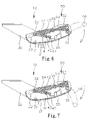
- FIG. 6 is similar to FIG. 2 but shows the reclining apparatus in a different position.
- FIG. 7 is similar to FIG. 6 but shows the reclining apparatus in a different position.
- FIG. 8 is similar to FIG. 7 but shows the reclining apparatus in a different position.
- FIG. 9 is similar to FIG. 8 but shows the reclining apparatus in a different position.
- FIG. 10 is a right side view of a chair equipped with a conventional reclining apparatus.
- FIG. 11 is similar to FIG. 10 but shows the chair equipped in a different position.
- FIG. 12 is a perspective view of the conventional reclining apparatus of FIG. 10 .
- FIG. 13 is an exploded view of the conventional reclining apparatus of FIG. 12 .
- a reclining apparatus 10 is used in a chair 72 .
- the chair 72 includes a base 70 for installment on the ground, a hydraulic cylinder 71 installed on the base 70 , a seat 90 connected with the hydraulic cylinder 71 via the reclining apparatus 10 and a backrest 80 installed on the seat 90 .
- the seat 90 can be reclined relative to the hydraulic cylinder 71 and kept in the reclined position by the reclining apparatus 10 .
- the reclining apparatus 10 includes a first joint 20 for attachment to the hydraulic cylinder 71 , a second joint 30 pivotally connected with the first joint 20 for supporting the seat 90 , a locking device 40 for locking the second joint 30 in one of several reclined positions relative to the first joint 20 , a tuning device 50 for tuning the reclined positions of the second joint 30 relative to the first joint 20 and a lifting device 60 for controlling the hydraulic cylinder 71 .
- the first joint 20 is in the form of a casing.
- the casing 20 includes a bottom and two lateral walls.
- An aperture 21 is defined in the bottom of the casing 20 .
- the hydraulic cylinder 71 is inserted into the casing 20 through the aperture 21 .
- An arched slot 22 and an aperture 24 are defined in each lateral wall of the casing 20 .
- the second joint 30 is in the form of a bracket.
- the bracket 30 includes a top member for supporting the seat 90 and two lateral members extending from the top member. Two apertures 33 and 34 are defined in each lateral member of the bracket 30 .
- a pin 31 is inserted in the apertures 33 of the bracket 30 and the apertures 24 of the casing 20 .
- Another pin 32 is inserted in the apertures 34 of the bracket 30 and the arched slots 22 of the casing 20 .
- the bracket 30 is pivotally connected with the casing 20 .
- the locking device 40 includes a mount 41 installed on the bottom of the casing 20 .
- a rod 42 is movably installed on the mount 41 .
- the rod 42 is connected with the pin 32 at an end and defines several dents 47 near an opposite end.
- a latch 43 is movably installed on the mount 41 .
- the rod 42 and the latch 43 are movable in transverse directions so that the latch 43 can enter the dents 47 .
- the bracket 30 is locked in selective one of several reclined positions relative to the casing 20 .
- a V-shaped lever 46 is pivotally installed on the bottom of the casing 20 .
- the V-shaped lever 46 includes a first end linked to the latch 43 and a second end connected with a link 45 .
- the link 45 is further connected with a shaft 44 .
- the shaft 44 is rotationally installed on the lateral walls of the casing 20 .
- a handle 48 extends transversely from the shaft 44 .
- pivotal movement of the handle 48 causes rotation of the shaft 44 .
- the rotation of the shaft 44 causes movement of the link 45 .
- the movement of the link 45 causes pivotal movement of the V-shaped lever 46 .
- the pivotal movement of the V-shaped lever 46 causes the movement of the latch 43 into and from the dents 47 .
- the tuning device 50 includes two springs 54 connected with the pin 32 .
- the springs 54 are further connected with a bar 55 .
- the bar 55 is further connected with a screw 53 .
- the screw 53 is further engaged with a nut/gear 52 .
- the nut/gear 52 is further engaged with a worm 51 .
- the worm 51 is rotationally installed on the lateral walls of the casing 20 .
- a crank 56 extends from the worm 51 .
- rocking of the crank 56 causes rotation of the worm 51 .
- the rotation of the worm 51 causes rotation of the nut/gear 52 .
- the rotation of the nut/gear 52 causes movement of the screw 53 .
- the movement of the screw 53 causes movement of the bar 55 .
- the movement of the bar 55 causes movement of the springs 54 .
- the movement of the springs 54 causes pivotal movement of the rod 42 about the latch 43 and therefore the reclining of the seat 90 relative to the hydraulic cylinder 71 .
- the lifting device 60 includes an L-shaped lever 62 with a first section and a second section extending transversely from the first section.
- the first section of the L-shaped lever 62 is for contact with the hydraulic cylinder 71 .
- the second section of the lever 62 is pivotally installed on one of the lateral walls of the casing 20 .
- the second section of the L-shaped lever 62 is further in contact with a tab 63 extending transversely from a shaft 61 .
- the shaft 61 is rotationally installed on the lateral walls of the casing 20 .
- a handle 64 extends transversely from the shaft 61 .
- pivotal movement of the handle 64 causes rotation of the shaft 61 .
- the rotation of the shaft 61 causes pivotal movement of the tab 63 .
- the pivotal movement of the tab 63 causes pivotal movement of the second section of the L-shaped lever 62 .
- the pivotal movement of the second section of the L-shaped lever 62 causes movement of the first section of the L-shaped lever 62 .
- the movement of the first section of the L-shaped lever 62 results in operation of the hydraulic cylinder 71 .
Abstract
A reclining apparatus is provided between a post and a seat of a chair. The reclining apparatus includes a first joint for attachment to the post, a second joint pivotally connected with the first joint for supporting the seat and a locking device for locking the second joint in one of several reclined positions relative to the casing.
Description
The present invention relates to a chair and, more particularly, to a reclining apparatus for use in a chair.
Referring to FIGS. 10 and 12 , a chair is equipped with a conventional reclining apparatus 100 so that the chair can be reclined. The chair includes a base 122, a hydraulic cylinder 119 installed on the base 122, a seat 124 connected with the hydraulic cylinder 119 by the reclining apparatus 100 and a backrest 126 connected with the seat 124.
Referring to FIGS. 12 and 13 , the reclining apparatus 100 includes a first joint 113 and a second joint 120 pivotally connected with the first joint 113. The joint 113 defines an aperture 118 for receiving the hydraulic cylinder 119. The second joint 120 is attached to the seat 124. The screw 114 includes a first end inserted through an aperture defined in the first joint 113 and a second end inserted through an aperture defined in the second joint 120. A nut 112 is screwed on the second end of the screw 114. A spring 117 is put around the screw 114. A nut/knob 115 is screwed on the first end of the screw 114. As the seat 124 is reclined relative to the hydraulic cylinder 119, the spring 117 is compressed so as to “counter.” The nut/knob 115 can be screwed or unscrewed on the screw 114 so as to adjust the range within which the seat 124 can be reclined relative to the hydraulic cylinder 119. However, the rotation of the nut/knob 115 is exhausting and time-consuming. Hence, a tongue 104 and a crankshaft 103 are used to adjust the range. The tongue 104 is movable into a space between the first joint 113 and the second joint 120 through a window 110 defined in a front plate 128 formed on the second joint 120. The tongue 104 includes a thick portion 106 and a thin portion 107 extending from the thick portion 106. When only the thin portion 107 is between the first joint 113 and the second joint 120, the range is large. When the thick portion 106 is between the first joint 113 and the second joint 120, the range is small. The crankshaft 103 is rotationally mounted on two lugs 108 formed on the front plate 128. The crankshaft 103 includes a first crank 101 and a second crank 102. The first crank 101 is inserted in a lug 105 formed on the tongue 104. The second crank 102 is for abutment against the front plate 128. The rotation of the crankshaft 103 causes the movement of the tongue 104. It is, however, impossible to retain the seat 124 in any reclined position relative to the hydraulic cylinder 119 with the conventional reclining apparatus 100.
The present invention is therefore intended to obviate or at least alleviate the problem encountered in the prior art.
It is the primary objective of the present invention to provide a chair with a reclining apparatus that can retain a seat in position relative to a hydraulic cylinder of the chair.
According to the present invention, a reclining apparatus is provided between a post and a seat of a chair. The reclining apparatus includes a first joint for attachment to the post, a second joint pivotally connected with the first joint for supporting the seat and a locking device for locking the second joint in one of several reclined positions relative to the casing.
Other objectives, advantages and novel features of the invention will become more apparent from the following detailed description in conjunction with the attached drawings.
The present invention will be described via detailed illustration of the preferred embodiment referring to the drawings.
Referring to FIGS. 1 and 2 , a reclining apparatus 10 is used in a chair 72. The chair 72 includes a base 70 for installment on the ground, a hydraulic cylinder 71 installed on the base 70, a seat 90 connected with the hydraulic cylinder 71 via the reclining apparatus 10 and a backrest 80 installed on the seat 90. The seat 90 can be reclined relative to the hydraulic cylinder 71 and kept in the reclined position by the reclining apparatus 10.
The reclining apparatus 10 includes a first joint 20 for attachment to the hydraulic cylinder 71, a second joint 30 pivotally connected with the first joint 20 for supporting the seat 90, a locking device 40 for locking the second joint 30 in one of several reclined positions relative to the first joint 20, a tuning device 50 for tuning the reclined positions of the second joint 30 relative to the first joint 20 and a lifting device 60 for controlling the hydraulic cylinder 71.
The first joint 20 is in the form of a casing. The casing 20 includes a bottom and two lateral walls. An aperture 21 is defined in the bottom of the casing 20. The hydraulic cylinder 71 is inserted into the casing 20 through the aperture 21. An arched slot 22 and an aperture 24 are defined in each lateral wall of the casing 20.
The second joint 30 is in the form of a bracket. The bracket 30 includes a top member for supporting the seat 90 and two lateral members extending from the top member. Two apertures 33 and 34 are defined in each lateral member of the bracket 30. A pin 31 is inserted in the apertures 33 of the bracket 30 and the apertures 24 of the casing 20. Another pin 32 is inserted in the apertures 34 of the bracket 30 and the arched slots 22 of the casing 20. Thus, the bracket 30 is pivotally connected with the casing 20.
Referring to FIG. 3 , the locking device 40 includes a mount 41 installed on the bottom of the casing 20. A rod 42 is movably installed on the mount 41. The rod 42 is connected with the pin 32 at an end and defines several dents 47 near an opposite end. A latch 43 is movably installed on the mount 41. The rod 42 and the latch 43 are movable in transverse directions so that the latch 43 can enter the dents 47. As the latch 43 enters a selective one the dents 47, the bracket 30 is locked in selective one of several reclined positions relative to the casing 20. A V-shaped lever 46 is pivotally installed on the bottom of the casing 20. The V-shaped lever 46 includes a first end linked to the latch 43 and a second end connected with a link 45. The link 45 is further connected with a shaft 44. The shaft 44 is rotationally installed on the lateral walls of the casing 20. A handle 48 extends transversely from the shaft 44.
Referring to FIGS. 3 and 4 , pivotal movement of the handle 48 causes rotation of the shaft 44. The rotation of the shaft 44 causes movement of the link 45. The movement of the link 45 causes pivotal movement of the V-shaped lever 46. The pivotal movement of the V-shaped lever 46 causes the movement of the latch 43 into and from the dents 47.
Referring to FIG. 2 , the tuning device 50 includes two springs 54 connected with the pin 32. The springs 54 are further connected with a bar 55. The bar 55 is further connected with a screw 53. The screw 53 is further engaged with a nut/gear 52. The nut/gear 52 is further engaged with a worm 51. The worm 51 is rotationally installed on the lateral walls of the casing 20. A crank 56 extends from the worm 51.
Referring to FIGS. 5–7 , rocking of the crank 56 causes rotation of the worm 51. The rotation of the worm 51 causes rotation of the nut/gear 52. The rotation of the nut/gear 52 causes movement of the screw 53. The movement of the screw 53 causes movement of the bar 55. The movement of the bar 55 causes movement of the springs 54. Through the pin 32, the movement of the springs 54 causes pivotal movement of the rod 42 about the latch 43 and therefore the reclining of the seat 90 relative to the hydraulic cylinder 71.
Referring to FIG. 3 , the lifting device 60 includes an L-shaped lever 62 with a first section and a second section extending transversely from the first section. The first section of the L-shaped lever 62 is for contact with the hydraulic cylinder 71. The second section of the lever 62 is pivotally installed on one of the lateral walls of the casing 20. The second section of the L-shaped lever 62 is further in contact with a tab 63 extending transversely from a shaft 61. The shaft 61 is rotationally installed on the lateral walls of the casing 20. A handle 64 extends transversely from the shaft 61.
Referring to FIGS. 8 and 9 , pivotal movement of the handle 64 causes rotation of the shaft 61. The rotation of the shaft 61 causes pivotal movement of the tab 63. The pivotal movement of the tab 63 causes pivotal movement of the second section of the L-shaped lever 62. The pivotal movement of the second section of the L-shaped lever 62 causes movement of the first section of the L-shaped lever 62. The movement of the first section of the L-shaped lever 62 results in operation of the hydraulic cylinder 71.
The present invention has been described via detailed illustration of the preferred embodiment. Those skilled in the art can derive variations from the preferred embodiment without departing from the scope of the present invention. Therefore, the preferred embodiment shall not limit the scope of the present invention defined in the claims.
Claims (20)
1. A reclining apparatus for use between a post and a seat of a chair, the reclining apparatus comprising:
a first joint for attachment to the post;
a second joint pivotally connected with the first joint and for supporting the seat;
a locking device for locking the second joint in one of several reclined positions relative to the first joint, wherein the locking device includes:
a rod connected with the second joint and movable on the first joint, the rod defines several dents; and
a latch movable on the first joint between a releasing position where the latch is away from the rod and a locking position where the latch is in one of the dents so as to lock the seat in one of the several reclined positions relative to the post; and
a spring connected between the first joint and the rod.
2. The reclining apparatus according to claim 1 wherein the rod and the latch are movable in transverse directions.
3. The reclining apparatus according to claim 1 wherein the locking device includes a mount installed on the first joint, and the rod is movably installed on the mount.
4. The reclining apparatus according to claim 1 wherein the locking device includes a handle for maneuvering the latch.
5. The reclining apparatus according to claim 4 wherein the locking device includes a linkage connected between the latch and the handle.
6. The reclining apparatus according to claim 5 wherein the linkage includes a shaft connected with the latch, and the handle extends transversely from the shaft.
7. The reclining apparatus according to claim 6 wherein the linkage includes a V-shaped lever pivotal on the first joint, and the V-shaped lever includes a first end linked to the latch and a second end linked to the shaft.
8. The reclining apparatus according to claim 7 wherein the linkage includes a link connected between the shaft and the second end of the V-shaped lever.
9. The reclining apparatus according to claim 1 including a pin connected between the second joint and the rod generally perpendicular to the rod, with the spring connected to the pin and the first joint.
10. The reclining apparatus according to claim 9 wherein the first joint defines two arched slots for receiving two ends of the pin.
11. A reclining apparatus for use between a post and a seat of a chair, the reclining apparatus comprising:
a first joint for attachment to the post;
a second joint pivotally connected with the first joint and for supporting the seat;
a locking device for locking the second joint in one of several reclined positions relative to the first joint wherein the locking device includes:
a rod connected with the second joint and movable on the first joint, the rod defines several dents, and
a latch movable on the first joint between a releasing position where the latch is away from the rod and a locking position where the latch is in one of the dents so as to lock the seat in one of the several reclined positions relative to the post; and
a pin connected between the second joint and the rod, wherein the first joint defines two arched slots for receiving two ends of the pin.
12. The reclining apparatus according to claim 11 including a pin for pivotally connecting the second joint with the first joint.
13. The reclining apparatus according to claim 11 including a tuning device for tuning the reclined positions of the second joint.
14. The reclining apparatus according to claim 11 wherein the post is a hydraulic cylinder.
15. The reclining apparatus according to claim 14 including a lifting device for controlling the hydraulic cylinder.
16. The reclining apparatus according to claim 15 wherein the lifting device includes a lever pivotally installed on the first joint, and the lever includes a first end for contact with the hydraulic cylinder and a second end to be maneuvered.
17. The reclining apparatus according to claim 16 wherein the lifting device includes a shaft rotationally installed on the lateral walls of the first joint and connected with the second end of the lever.
18. A reclining apparatus for use between a post and a seat of a chair, the reclining apparatus comprising a first joint for attachment to the post, a second joint pivotally connected with the first joint and for supporting the seat, a locking device for locking the second joint in one of several reclined positions relative to the first joint and a tuning device for tuning the reclined positions of the second joint, wherein the tuning device includes at least one spring connected with the second joint; a screw connected with the spring and non-rotationally installed on the first joint; a nut engaged with the screw and rotationally installed on the first joint so that screwing of the nut on the screw causes pivotal movement of the second joint relative to the first joint; and a worm rotationally installed on the first joint, and wherein the nut is a nut/gear engaged with the screw internally and engaged with the worm externally.
19. The reclining apparatus according to claim 18 wherein the tuning device includes a crank extending transversely from the worm.
20. The reclining apparatus according to claim 1 further comprising:
a screw connected with the spring and non-rotationally installed on the first joint; and
a nut engaged with the screw and rotationally installed on the first joint so that screwing of the nut on the screw causes pivotal movement of the second joint relative to the first joint.
Priority Applications (1)
| Application Number | Priority Date | Filing Date | Title |
|---|---|---|---|
| US10/761,095 US7147285B2 (en) | 2004-01-20 | 2004-01-20 | Reclining apparatus for chair |
Applications Claiming Priority (1)
| Application Number | Priority Date | Filing Date | Title |
|---|---|---|---|
| US10/761,095 US7147285B2 (en) | 2004-01-20 | 2004-01-20 | Reclining apparatus for chair |
Publications (2)
| Publication Number | Publication Date |
|---|---|
| US20050156453A1 US20050156453A1 (en) | 2005-07-21 |
| US7147285B2 true US7147285B2 (en) | 2006-12-12 |
Family
ID=34750148
Family Applications (1)
| Application Number | Title | Priority Date | Filing Date |
|---|---|---|---|
| US10/761,095 Expired - Fee Related US7147285B2 (en) | 2004-01-20 | 2004-01-20 | Reclining apparatus for chair |
Country Status (1)
| Country | Link |
|---|---|
| US (1) | US7147285B2 (en) |
Cited By (28)
| Publication number | Priority date | Publication date | Assignee | Title |
|---|---|---|---|---|
| US20060255636A1 (en) * | 2005-04-27 | 2006-11-16 | Donati S.P.A. | Mechanism for adjusting the inclination of backrests in chairs and arm-chairs, particularly in office chairs |
| US20070057553A1 (en) * | 2005-03-01 | 2007-03-15 | Roslund Richard N | Tilt control mechanism for a chair |
| US20070290537A1 (en) * | 2006-06-13 | 2007-12-20 | Tung Yu Oa Co., Ltd. | Recliner |
| US20080174161A1 (en) * | 2007-01-22 | 2008-07-24 | Sedus Stoll Ag | Chair having a tiltable seat |
| US20090008979A1 (en) * | 2007-04-06 | 2009-01-08 | L & P Property Management Company | Adjustment device for a reclining chair |
| US20090008978A1 (en) * | 2007-04-06 | 2009-01-08 | L & P Property Management Company | Adjustment device for adjustable chairs |
| US20090021065A1 (en) * | 2006-04-27 | 2009-01-22 | Egon Brauning | Mechanism for a Chair |
| US7530637B1 (en) * | 2008-03-18 | 2009-05-12 | Yao-Chuan Wu | Chair assembly |
| US7614697B1 (en) * | 2008-06-06 | 2009-11-10 | Fon Chin Industrial Co., Ltd. | Coupling mechanism interposed between a seat and a back of a chair to prevent a reclining motion of the back from tilting the seat |
| US20090302656A1 (en) * | 2008-06-06 | 2009-12-10 | Knoll, Inc. | Preference Control Mechanism |
| USD613084S1 (en) | 2008-12-12 | 2010-04-06 | Formway Furniture Limited | Chair |
| USD615784S1 (en) | 2008-04-09 | 2010-05-18 | Formway Furniture Limited | Chair back |
| USD616213S1 (en) | 2008-04-09 | 2010-05-25 | Formway Furniture Limited | Chair |
| US20100141002A1 (en) * | 2008-06-04 | 2010-06-10 | Kurrasch Andrew J | Biasing mechanism |
| US8029060B2 (en) | 2006-10-04 | 2011-10-04 | Formway Furniture Limited | Chair |
| US20110278893A1 (en) * | 2010-05-13 | 2011-11-17 | L & P Property Management Company | Chair-specific adjustment device |
| US20130069408A1 (en) * | 2011-09-15 | 2013-03-21 | Yucheng Chen | Chair chassis |
| US8528973B2 (en) * | 2010-04-15 | 2013-09-10 | Sidiz, Inc. | Adjusting mechanism for adjusting a restoring force that acts on a backrest of a chair, and office chair with such an adjusting mechanism |
| US20140306503A1 (en) * | 2013-04-11 | 2014-10-16 | Hangzhou Zhongtai Industrial Group Co., Ltd. | Chair Chassis |
| US9004597B2 (en) | 2012-09-20 | 2015-04-14 | Steelcase Inc. | Chair back mechanism and control assembly |
| US9033421B2 (en) | 2008-12-12 | 2015-05-19 | Formway Furniture Limited | Chair, a support, and components |
| DE102014104870A1 (en) * | 2014-04-04 | 2015-10-08 | Bock 1 Gmbh & Co. Kg | Mechanics for an office chair |
| US9894999B2 (en) * | 2013-02-07 | 2018-02-20 | Bock 1 Gmbh & Co. Kg | Mechanism for an office chair |
| US10376066B2 (en) * | 2017-09-22 | 2019-08-13 | Dongguan Kentec Office Seating Co., Ltd. | Flexible support device for chair back tilting |
| US11109683B2 (en) | 2019-02-21 | 2021-09-07 | Steelcase Inc. | Body support assembly and method for the use and assembly thereof |
| US11304528B2 (en) | 2012-09-20 | 2022-04-19 | Steelcase Inc. | Chair assembly with upholstery covering |
| US11357329B2 (en) | 2019-12-13 | 2022-06-14 | Steelcase Inc. | Body support assembly and methods for the use and assembly thereof |
| US20220378208A1 (en) * | 2019-06-17 | 2022-12-01 | Quali Co., Ltd. | Tilt chair |
Families Citing this family (7)
| Publication number | Priority date | Publication date | Assignee | Title |
|---|---|---|---|---|
| DK1985206T3 (en) * | 2006-02-15 | 2013-12-09 | Perez Vicente Berbegal | Office chair |
| US20070228801A1 (en) * | 2006-04-03 | 2007-10-04 | Leggett & Platt Canada Co. | Chair control |
| US8025336B2 (en) * | 2008-10-31 | 2011-09-27 | Midmark Corporation | Dental chair |
| US7708344B1 (en) | 2008-10-31 | 2010-05-04 | Midmark Corporation | Patient chair with locking assembly |
| US7914076B2 (en) * | 2008-10-31 | 2011-03-29 | Midmark Corporation | Device with a limit switch and trunnion |
| ITMI20090096U1 (en) * | 2009-03-25 | 2010-09-26 | Donati Spa | DRIVE CRANK FOR A CHAIR OF ADJUSTING A CHAIR, OR ANOTHER SEAT DEVICE |
| IT201700112144A1 (en) * | 2017-10-06 | 2019-04-06 | Co Fe Mo Ind S R L | OSCILLATION SYSTEM FOR CHAIRS |
Citations (20)
| Publication number | Priority date | Publication date | Assignee | Title |
|---|---|---|---|---|
| US4537445A (en) * | 1983-05-10 | 1985-08-27 | Meiko Industrial Co., Ltd. | Chair |
| US4640547A (en) * | 1983-09-17 | 1987-02-03 | Heinrich Fromme | Adjustable swivel chair |
| US4641886A (en) * | 1984-10-24 | 1987-02-10 | Burositz Mobelfabrik Friedrich-W. Dauphin GmbH & Co. | Gas spring arrangement, especially for a backrest support for office chairs |
| US4662680A (en) * | 1984-10-24 | 1987-05-05 | Buerositzmobelfabrik Friedrich-W. Dauphin GmbH & Company | Activating device for the release tappet of a longitudinally adjustable gas spring |
| US4747640A (en) * | 1986-09-24 | 1988-05-31 | Giroflex Entwicklungs Ag | Chair support |
| US4787673A (en) * | 1986-09-24 | 1988-11-29 | Giroflex Entwicklungs Ag | Chair support with adjustment device |
| US4834453A (en) * | 1986-09-08 | 1989-05-30 | Girsberger Holding Ag | Swivel chair |
| US5026117A (en) * | 1987-11-10 | 1991-06-25 | Steelcase Inc. | Controller for seating and the like |
| US5295731A (en) * | 1991-04-20 | 1994-03-22 | Friedrich W. Dauphin Gmbh & Co. Entwicklungs- Und Beteiligungs-Kg | Chair, in particular office chair |
| US5601337A (en) * | 1993-07-27 | 1997-02-11 | Uchida Yoko Co., Ltd. | Chair |
| US6276755B1 (en) * | 1999-11-09 | 2001-08-21 | Tung-Hua Su | Swivel arrangement for a chair seat |
| US6419320B1 (en) * | 2001-02-28 | 2002-07-16 | Tung Yu Oa Co. Ltd. | Base manipulation device for office chair |
| US6523896B1 (en) * | 1999-07-06 | 2003-02-25 | Peter Roder | Chair |
| US6588843B1 (en) * | 2000-10-06 | 2003-07-08 | Ghsp, Incorporated | Chair control |
| US6709056B2 (en) * | 2001-05-18 | 2004-03-23 | Bock-1 Gmbh & Co. | Preloaded spring arrangement, in particular for spring loading office chair synchronizing mechanisms |
| US20040140703A1 (en) * | 2002-09-07 | 2004-07-22 | Bock-1 Gmbh & Co. | Synchronizing mechanism for office chairs |
| US6840578B1 (en) * | 2003-09-16 | 2005-01-11 | Wen-Fa Su | Chair improvement structure |
| US6874853B2 (en) * | 2002-01-08 | 2005-04-05 | Dauphin Entwicklungs- U. Beteiligungs-Gmbh | Chair |
| US6923503B2 (en) * | 2002-10-16 | 2005-08-02 | Icf S.P.A. | Chair with movable seat and backrest |
| US20050184570A1 (en) * | 2002-03-29 | 2005-08-25 | Sanchez Gary L. | Task chair |
-
2004
- 2004-01-20 US US10/761,095 patent/US7147285B2/en not_active Expired - Fee Related
Patent Citations (21)
| Publication number | Priority date | Publication date | Assignee | Title |
|---|---|---|---|---|
| US4537445A (en) * | 1983-05-10 | 1985-08-27 | Meiko Industrial Co., Ltd. | Chair |
| US4640547A (en) * | 1983-09-17 | 1987-02-03 | Heinrich Fromme | Adjustable swivel chair |
| US4641886A (en) * | 1984-10-24 | 1987-02-10 | Burositz Mobelfabrik Friedrich-W. Dauphin GmbH & Co. | Gas spring arrangement, especially for a backrest support for office chairs |
| US4662680A (en) * | 1984-10-24 | 1987-05-05 | Buerositzmobelfabrik Friedrich-W. Dauphin GmbH & Company | Activating device for the release tappet of a longitudinally adjustable gas spring |
| US4834453A (en) * | 1986-09-08 | 1989-05-30 | Girsberger Holding Ag | Swivel chair |
| US4747640A (en) * | 1986-09-24 | 1988-05-31 | Giroflex Entwicklungs Ag | Chair support |
| US4787673A (en) * | 1986-09-24 | 1988-11-29 | Giroflex Entwicklungs Ag | Chair support with adjustment device |
| US5026117A (en) * | 1987-11-10 | 1991-06-25 | Steelcase Inc. | Controller for seating and the like |
| US5160184A (en) * | 1989-07-18 | 1992-11-03 | Steelcase, Inc. | Controller for seating and the like |
| US5295731A (en) * | 1991-04-20 | 1994-03-22 | Friedrich W. Dauphin Gmbh & Co. Entwicklungs- Und Beteiligungs-Kg | Chair, in particular office chair |
| US5601337A (en) * | 1993-07-27 | 1997-02-11 | Uchida Yoko Co., Ltd. | Chair |
| US6523896B1 (en) * | 1999-07-06 | 2003-02-25 | Peter Roder | Chair |
| US6276755B1 (en) * | 1999-11-09 | 2001-08-21 | Tung-Hua Su | Swivel arrangement for a chair seat |
| US6588843B1 (en) * | 2000-10-06 | 2003-07-08 | Ghsp, Incorporated | Chair control |
| US6419320B1 (en) * | 2001-02-28 | 2002-07-16 | Tung Yu Oa Co. Ltd. | Base manipulation device for office chair |
| US6709056B2 (en) * | 2001-05-18 | 2004-03-23 | Bock-1 Gmbh & Co. | Preloaded spring arrangement, in particular for spring loading office chair synchronizing mechanisms |
| US6874853B2 (en) * | 2002-01-08 | 2005-04-05 | Dauphin Entwicklungs- U. Beteiligungs-Gmbh | Chair |
| US20050184570A1 (en) * | 2002-03-29 | 2005-08-25 | Sanchez Gary L. | Task chair |
| US20040140703A1 (en) * | 2002-09-07 | 2004-07-22 | Bock-1 Gmbh & Co. | Synchronizing mechanism for office chairs |
| US6923503B2 (en) * | 2002-10-16 | 2005-08-02 | Icf S.P.A. | Chair with movable seat and backrest |
| US6840578B1 (en) * | 2003-09-16 | 2005-01-11 | Wen-Fa Su | Chair improvement structure |
Cited By (72)
| Publication number | Priority date | Publication date | Assignee | Title |
|---|---|---|---|---|
| US20090179473A1 (en) * | 2005-03-01 | 2009-07-16 | Roslund Richard N | Tilt control mechanism for a chair |
| US20070057553A1 (en) * | 2005-03-01 | 2007-03-15 | Roslund Richard N | Tilt control mechanism for a chair |
| US7997652B2 (en) * | 2005-03-01 | 2011-08-16 | Haworth, Inc. | Tilt control mechanism for a chair |
| US20080203797A1 (en) * | 2005-03-01 | 2008-08-28 | Haworth, Inc. | Control mechanism for a chair |
| US7429081B2 (en) * | 2005-03-01 | 2008-09-30 | Haworth, Inc. | Tilt control mechanism for a chair |
| US20110012395A1 (en) * | 2005-03-01 | 2011-01-20 | Haworth, Inc. | Tilt control mechanism for a chair |
| US7735923B2 (en) | 2005-03-01 | 2010-06-15 | Haworth, Inc. | Tilt control mechanism for a chair |
| US7513570B2 (en) * | 2005-03-01 | 2009-04-07 | Haworth, Inc. | Control mechanism for a chair |
| US7946651B2 (en) * | 2005-04-27 | 2011-05-24 | Donati S.P.A. | Mechanism for adjusting the inclination of backrests in chairs and arm-chairs, particularly in office chairs |
| US20060255636A1 (en) * | 2005-04-27 | 2006-11-16 | Donati S.P.A. | Mechanism for adjusting the inclination of backrests in chairs and arm-chairs, particularly in office chairs |
| US20090021065A1 (en) * | 2006-04-27 | 2009-01-22 | Egon Brauning | Mechanism for a Chair |
| US20070290537A1 (en) * | 2006-06-13 | 2007-12-20 | Tung Yu Oa Co., Ltd. | Recliner |
| US8087727B2 (en) | 2006-10-04 | 2012-01-03 | Formway Furniture Limited | Chair |
| US8888183B2 (en) | 2006-10-04 | 2014-11-18 | Formway Furniture Limited | Chair |
| US8668265B2 (en) | 2006-10-04 | 2014-03-11 | Formway Furniture Limited | Chair |
| US8613481B2 (en) | 2006-10-04 | 2013-12-24 | Formway Furniture Limited | Chair |
| US8096615B2 (en) | 2006-10-04 | 2012-01-17 | Formay Furniture Limited | Chair |
| US8029060B2 (en) | 2006-10-04 | 2011-10-04 | Formway Furniture Limited | Chair |
| US7503626B2 (en) * | 2007-01-22 | 2009-03-17 | Sedus Stoll Ag | Chair having a tiltable seat |
| US20080174161A1 (en) * | 2007-01-22 | 2008-07-24 | Sedus Stoll Ag | Chair having a tiltable seat |
| US7815257B2 (en) | 2007-04-06 | 2010-10-19 | L & P Property Management Company | Adjustment device for adjustable chairs |
| US7866749B2 (en) | 2007-04-06 | 2011-01-11 | L & P Property Management Company | Adjustment device for a reclining chair |
| US20090008978A1 (en) * | 2007-04-06 | 2009-01-08 | L & P Property Management Company | Adjustment device for adjustable chairs |
| US20090008979A1 (en) * | 2007-04-06 | 2009-01-08 | L & P Property Management Company | Adjustment device for a reclining chair |
| US7530637B1 (en) * | 2008-03-18 | 2009-05-12 | Yao-Chuan Wu | Chair assembly |
| USD616213S1 (en) | 2008-04-09 | 2010-05-25 | Formway Furniture Limited | Chair |
| USD615784S1 (en) | 2008-04-09 | 2010-05-18 | Formway Furniture Limited | Chair back |
| US20100141002A1 (en) * | 2008-06-04 | 2010-06-10 | Kurrasch Andrew J | Biasing mechanism |
| US20090302656A1 (en) * | 2008-06-06 | 2009-12-10 | Knoll, Inc. | Preference Control Mechanism |
| US8172324B2 (en) * | 2008-06-06 | 2012-05-08 | Knoll, Inc. | Preference control mechanism |
| US8348342B2 (en) | 2008-06-06 | 2013-01-08 | Knoll, Inc. | Preference control mechanism |
| US7614697B1 (en) * | 2008-06-06 | 2009-11-10 | Fon Chin Industrial Co., Ltd. | Coupling mechanism interposed between a seat and a back of a chair to prevent a reclining motion of the back from tilting the seat |
| USD613084S1 (en) | 2008-12-12 | 2010-04-06 | Formway Furniture Limited | Chair |
| US9033421B2 (en) | 2008-12-12 | 2015-05-19 | Formway Furniture Limited | Chair, a support, and components |
| US9622579B2 (en) | 2008-12-12 | 2017-04-18 | Formway Furniture Limited | Chair, a support, and components |
| US8528973B2 (en) * | 2010-04-15 | 2013-09-10 | Sidiz, Inc. | Adjusting mechanism for adjusting a restoring force that acts on a backrest of a chair, and office chair with such an adjusting mechanism |
| US8632130B2 (en) * | 2010-05-13 | 2014-01-21 | L & P Property Management Company | Chair-specific adjustment device |
| US20110278893A1 (en) * | 2010-05-13 | 2011-11-17 | L & P Property Management Company | Chair-specific adjustment device |
| US20130069408A1 (en) * | 2011-09-15 | 2013-03-21 | Yucheng Chen | Chair chassis |
| US9044094B2 (en) * | 2011-09-15 | 2015-06-02 | Yucheng Chen | Chair chassis |
| US9861201B2 (en) | 2012-09-20 | 2018-01-09 | Steelcase, Inc. | Chair assembly |
| US10206507B2 (en) | 2012-09-20 | 2019-02-19 | Steelcase Inc. | Control assembly for chair |
| US9027999B2 (en) | 2012-09-20 | 2015-05-12 | Steelcase Inc. | Control assembly for chair |
| US9027998B2 (en) | 2012-09-20 | 2015-05-12 | Steelcase Inc. | Chair assembly |
| US9027997B2 (en) | 2012-09-20 | 2015-05-12 | Steelcasel Inc. | Chair assembly |
| US9010859B2 (en) | 2012-09-20 | 2015-04-21 | Steelcase Inc. | Chair assembly |
| US9004597B2 (en) | 2012-09-20 | 2015-04-14 | Steelcase Inc. | Chair back mechanism and control assembly |
| US9049935B2 (en) | 2012-09-20 | 2015-06-09 | Steelcase Inc. | Control assembly for chair |
| US11304528B2 (en) | 2012-09-20 | 2022-04-19 | Steelcase Inc. | Chair assembly with upholstery covering |
| USD742676S1 (en) | 2012-09-20 | 2015-11-10 | Steelcase Inc. | Chair |
| USD742677S1 (en) | 2012-09-20 | 2015-11-10 | Steelcase Inc. | Chair |
| US9345328B2 (en) | 2012-09-20 | 2016-05-24 | Steelcase Inc. | Chair assembly with upholstery covering |
| US9451826B2 (en) | 2012-09-20 | 2016-09-27 | Steelcase Inc. | Chair assembly |
| US9462888B2 (en) | 2012-09-20 | 2016-10-11 | Steelcase Inc. | Control assembly for chair |
| US9492013B2 (en) | 2012-09-20 | 2016-11-15 | Steelcase Inc. | Chair back mechanism and control assembly |
| US9526339B2 (en) | 2012-09-20 | 2016-12-27 | Steelcase Inc. | Control assembly for chair |
| US9022476B2 (en) | 2012-09-20 | 2015-05-05 | Steelcase Inc. | Control assembly for chair |
| US9918552B2 (en) | 2012-09-20 | 2018-03-20 | Steelcase Inc. | Control assembly for chair |
| US9844267B2 (en) | 2012-09-20 | 2017-12-19 | Steelcase Inc. | Chair back mechanism and control assembly |
| US9894999B2 (en) * | 2013-02-07 | 2018-02-20 | Bock 1 Gmbh & Co. Kg | Mechanism for an office chair |
| US20140306503A1 (en) * | 2013-04-11 | 2014-10-16 | Hangzhou Zhongtai Industrial Group Co., Ltd. | Chair Chassis |
| US8939509B2 (en) * | 2013-04-11 | 2015-01-27 | Hangzhou Zhongtai Industrial Group Co., Ltd. | Chair chassis |
| DE102014104870A1 (en) * | 2014-04-04 | 2015-10-08 | Bock 1 Gmbh & Co. Kg | Mechanics for an office chair |
| US9549614B2 (en) | 2014-04-04 | 2017-01-24 | Bock 1 Gmbh & Co. Kg | Mechanism for an office chair |
| US10376066B2 (en) * | 2017-09-22 | 2019-08-13 | Dongguan Kentec Office Seating Co., Ltd. | Flexible support device for chair back tilting |
| US11109683B2 (en) | 2019-02-21 | 2021-09-07 | Steelcase Inc. | Body support assembly and method for the use and assembly thereof |
| US11602223B2 (en) | 2019-02-21 | 2023-03-14 | Steelcase Inc. | Body support assembly and methods for the use and assembly thereof |
| US11910934B2 (en) | 2019-02-21 | 2024-02-27 | Steelcase Inc. | Body support assembly and methods for the use and assembly thereof |
| US20220378208A1 (en) * | 2019-06-17 | 2022-12-01 | Quali Co., Ltd. | Tilt chair |
| US11357329B2 (en) | 2019-12-13 | 2022-06-14 | Steelcase Inc. | Body support assembly and methods for the use and assembly thereof |
| US11786039B2 (en) | 2019-12-13 | 2023-10-17 | Steelcase Inc. | Body support assembly and methods for the use and assembly thereof |
| US11805913B2 (en) | 2019-12-13 | 2023-11-07 | Steelcase Inc. | Body support assembly and methods for the use and assembly thereof |
Also Published As
| Publication number | Publication date |
|---|---|
| US20050156453A1 (en) | 2005-07-21 |
Similar Documents
| Publication | Publication Date | Title |
|---|---|---|
| US7147285B2 (en) | Reclining apparatus for chair | |
| KR101045453B1 (en) | Low profile seat suspension | |
| US9364378B2 (en) | Wheelchair including a collapsible and/or angle adjustable backrest frame | |
| US6751819B2 (en) | Tool assembly with a tire repairing wrench | |
| US5664842A (en) | Height-adjustable armrest unit for a chair | |
| US6616155B2 (en) | Resilient force-adjusting structure for skate board | |
| US6293575B1 (en) | Foldable frame assembly for a bicycle | |
| US20180037183A1 (en) | Lever-Actuated Operator Protection Apparatus | |
| US5930902A (en) | Saw with a removable saw blade | |
| US20060086553A1 (en) | Electric vehicle with partitionable structure | |
| CA2201253A1 (en) | Chair control | |
| US20070290537A1 (en) | Recliner | |
| ZA200905256B (en) | Lever lockout assembly | |
| US20090173860A1 (en) | Mounting system for flat panel display | |
| US8708310B2 (en) | Flooring installation tool with adjustable shoe | |
| US9132708B1 (en) | Inverted bent bar trailer hitch | |
| US5910193A (en) | Adjustable brake lever assembly | |
| JP3056114B2 (en) | table | |
| JP4254354B2 (en) | Seat-mounted drive robot | |
| KR101843429B1 (en) | Torque wrench system | |
| JP2000328602A (en) | Armrest structure of driver's seat in working machine | |
| JP2575965Y2 (en) | Tilt steering system | |
| JP2004183837A (en) | Valve operating device and pilot valve comprising the same | |
| US6283179B1 (en) | Wood planing machine with a carriage locking mechanism | |
| US1781172A (en) | Latch |
Legal Events
| Date | Code | Title | Description |
|---|---|---|---|
| AS | Assignment |
Owner name: TUNG YU OA CO., LTD., TAIWAN Free format text: ASSIGNMENT OF ASSIGNORS INTEREST;ASSIGNOR:LIN, YU-HONG;REEL/FRAME:014919/0755 Effective date: 20040115 |
|
| REMI | Maintenance fee reminder mailed | ||
| LAPS | Lapse for failure to pay maintenance fees | ||
| STCH | Information on status: patent discontinuation |
Free format text: PATENT EXPIRED DUE TO NONPAYMENT OF MAINTENANCE FEES UNDER 37 CFR 1.362 |
|
| FP | Lapsed due to failure to pay maintenance fee |
Effective date: 20101212 |