US7134820B2 - Integrated anchoring system and composite plate for a trailer side wall joint - Google Patents
Integrated anchoring system and composite plate for a trailer side wall joint Download PDFInfo
- Publication number
- US7134820B2 US7134820B2 US10/999,090 US99909004A US7134820B2 US 7134820 B2 US7134820 B2 US 7134820B2 US 99909004 A US99909004 A US 99909004A US 7134820 B2 US7134820 B2 US 7134820B2
- Authority
- US
- United States
- Prior art keywords
- plate
- vehicle body
- track member
- plates
- joint
- Prior art date
- Legal status (The legal status is an assumption and is not a legal conclusion. Google has not performed a legal analysis and makes no representation as to the accuracy of the status listed.)
- Expired - Lifetime
Links
- 238000004873 anchoring Methods 0.000 title claims abstract description 44
- 239000002131 composite material Substances 0.000 title abstract description 27
- 229910052782 aluminium Inorganic materials 0.000 claims description 11
- XAGFODPZIPBFFR-UHFFFAOYSA-N aluminium Chemical compound [Al] XAGFODPZIPBFFR-UHFFFAOYSA-N 0.000 claims description 11
- 229910000831 Steel Inorganic materials 0.000 claims description 7
- 239000010959 steel Substances 0.000 claims description 7
- 238000010276 construction Methods 0.000 description 4
- 230000008901 benefit Effects 0.000 description 3
- 229910001335 Galvanized steel Inorganic materials 0.000 description 2
- 239000008397 galvanized steel Substances 0.000 description 2
- 238000003780 insertion Methods 0.000 description 2
- 230000037431 insertion Effects 0.000 description 2
- 238000004519 manufacturing process Methods 0.000 description 2
- 229910052751 metal Inorganic materials 0.000 description 2
- 239000002184 metal Substances 0.000 description 2
- 229910000760 Hardened steel Inorganic materials 0.000 description 1
- 239000004743 Polypropylene Substances 0.000 description 1
- 239000000853 adhesive Substances 0.000 description 1
- 230000001070 adhesive effect Effects 0.000 description 1
- 229920001903 high density polyethylene Polymers 0.000 description 1
- 239000004700 high-density polyethylene Substances 0.000 description 1
- 239000000463 material Substances 0.000 description 1
- 239000007769 metal material Substances 0.000 description 1
- 238000012986 modification Methods 0.000 description 1
- 230000004048 modification Effects 0.000 description 1
- 229910052755 nonmetal Inorganic materials 0.000 description 1
- 230000008520 organization Effects 0.000 description 1
- 239000004033 plastic Substances 0.000 description 1
- 229920003023 plastic Polymers 0.000 description 1
- -1 polypropylene Polymers 0.000 description 1
- 229920001155 polypropylene Polymers 0.000 description 1
- 230000002787 reinforcement Effects 0.000 description 1
- 229920001169 thermoplastic Polymers 0.000 description 1
- 239000004416 thermosoftening plastic Substances 0.000 description 1
Images


Classifications
-
- B—PERFORMING OPERATIONS; TRANSPORTING
- B62—LAND VEHICLES FOR TRAVELLING OTHERWISE THAN ON RAILS
- B62D—MOTOR VEHICLES; TRAILERS
- B62D33/00—Superstructures for load-carrying vehicles
- B62D33/04—Enclosed load compartments ; Frameworks for movable panels, tarpaulins or side curtains
- B62D33/046—Enclosed load compartments ; Frameworks for movable panels, tarpaulins or side curtains built up with flat self-supporting panels; Fixed connections between panels
-
- B—PERFORMING OPERATIONS; TRANSPORTING
- B60—VEHICLES IN GENERAL
- B60P—VEHICLES ADAPTED FOR LOAD TRANSPORTATION OR TO TRANSPORT, TO CARRY, OR TO COMPRISE SPECIAL LOADS OR OBJECTS
- B60P7/00—Securing or covering of load on vehicles
- B60P7/06—Securing of load
- B60P7/135—Securing or supporting by load bracing means
- B60P7/15—Securing or supporting by load bracing means the load bracing means comprising a movable bar
Definitions
- anchoring systems exist for use in the interior of trailers for supporting cargo or a removable deck which supports cargo. Two such systems are provided by Kinedyne Corporation and Ancra International LLC.
- Each of these anchoring systems have a number of elongated track members which generally run along the interior side walls of a trailer, from a position proximate to the roof of the trailer to a position proximate to a top of a scuff plate provided on the respective side wall proximate to the floor of the trailer.
- the track members are attached to the interior surface of the side walls and, thus, extend into the interior space of the trailer body.
- the track members can be easily damaged by forklifts or other means.
- the track members because the track members extend into the interior space of the trailer body, the track members take up room within the trailer body, thus leaving less room for cargo to be stored within the trailer body.
- a track member of an anchoring system that will have a lower profile on the inside of the trailer body such as to help prevent the damage of the track member by forklifts or other means and to allow for more cargo to be stored within the trailer body.
- the present invention provides such an anchoring system.
- a primary object of the invention is to provide a joint between composite plate side walls of a trailer body which includes an anchoring system.
- Another object of the invention is to provide an anchoring system which will be caused less damage by forklifts or other means than prior art anchoring systems.
- Another object of the invention is to provide a joint between composite plate side walls which includes an anchoring system where the composite plates reinforce a track member of the anchoring system such that the track member cannot spread even if it is hit with a forklift.
- Yet another object of the invention is to provide a joint between composite plate side walls which includes an anchoring system where the anchoring system is not a structural post of the joint as the composite plates provide the structural strength for the side walls.
- a further object of the invention is to provide a joint which includes an anchoring system that can be removed from between composite plate side walls without requiring the entire side wall to be dismantled.
- Still another object of the invention is to provide an anchoring system that is formed of roll formed 14 gauge steel, as opposed to extruded aluminum, as the roll formed 14 gauge steel allows for better manufacturing.
- the present invention provides a novel joint between composite plate side walls of a trailer body which includes an anchoring system.
- the anchoring system includes track members which are provided at multiple points on each side wall between the composite plates. Beams extend between the respective track members by attachments and are attached thereto. The beams can be moved up and down along the tracks and support cargo or a removable deck which supports the cargo.
- the track members can be removed from the side walls without dismantling the entire joint.
- Splicing members which also form part of the joint, are attached to the side walls on the outside of the trailer body.
- FIG. 1 is a perspective view of a trailer and a tractor
- FIG. 2 is a perspective view of the interior of the trailer of FIG. 1 having joints which include an anchoring system which incorporates the features of a first embodiment of the invention
- FIG. 3 is a partial perspective view of the joint shown in FIG. 2 ;
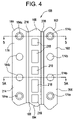
- FIG. 4 is a partial front elevational view of a track member which forms a portion of the anchoring system according to the first embodiment of the invention
- FIG. 5 is a cross-sectional view of the track member shown in FIG. 4 along line 5 — 5 ;
- FIG. 5A is a cross-sectional view of the track member shown in FIG. 4 along line 5 A— 5 A;
- FIG. 6 is a first cross-sectional view of the joint including the track member shown in FIG. 5 ;
- FIG. 6A is a second cross-sectional view of the joint including the track member shown in FIG. 5A ;
- FIG. 7 is a cross-sectional view of the joint having a track member formed from rolled steel
- FIG. 8 is a partial perspective view of the joint which includes an anchoring system which incorporates the features of a second embodiment of the invention.
- FIG. 9 is a partial front elevational view of a track member which forms a portion of the anchoring system according to the second embodiment of the invention.
- FIG. 10 is a cross-sectional view of the track member shown in FIG. 9 along line 10 — 10 ;
- FIG. 10A is a cross-sectional view of the track member shown in FIG. 9 along line 10 A— 10 A;
- FIG. 11 is a first cross-sectional view of the joint including the track member shown in FIG. 10 ;
- FIG. 11A is a second cross-sectional view of the joint including the track member shown in FIG. 10A ;
- FIG. 12 is a cross-sectional view of the joint including the track member shown in FIG. 10 ;
- FIG. 13 is a perspective view of the interior of the trailer of FIG. 1 having joints which include an anchoring system which incorporates the features of a second embodiment of the invention.
- the present invention provides a novel joint 46 between side plates 44 of the side walls 24 of a trailer 20 which includes an anchoring system 148 , 348 .
- the anchoring system 148 , 348 is used to support cargo 236 , 436 or to support a deck 238 , 438 which supports the cargo 236 , 436 .
- a first embodiment of the joint 46 shown in FIGS. 2–7 and a second embodiment of the joint 46 is shown in FIGS. 8–13 .
- Like elements are denoted with like reference numerals with the first embodiment being in the one and two hundreds, and the second embodiment being in the three and four hundreds.
- the trailer 20 which is shown in FIG. 1 connected to a tractor 21 , includes a body 22 formed from a pair of rectangular side walls 24 a front wall 26 , rear doors 28 , a top panel or roof 30 and a floor 32 .
- the floor 32 is supported by a conventional rear undercarriage assembly 34 and has a landing gear 36 secured thereunder.
- the roof 30 and an upper portion of the side walls 24 are secured to a top rail 38 while the floor 32 and a lower portion of the side walls 24 are secured to a bottom rail 40 .
- the interior of the trailer 20 has scuff plates 42 which generally extend along the entire length of the side walls 24 and from the floor 32 to a position below the roof 30 .
- Each side wall 24 includes a plurality of vertical upstanding composite side plates 44 joined together by the joints 46 .
- Each joint 46 includes the anchoring system 148 , 348 and a splicing plate 50 .
- the anchoring system 148 , 348 is attached to the inner surface of the side plates 44 and between the side plates 44 .
- the splicing plate 50 is attached to the exterior of the side plates 44 .
- At least two plates 44 a , 44 b are joined together by the joints 46 to form the side wall 24 of the trailer body 22 . While only a portion of two joined plates 44 a , 44 b are shown in some of the drawings, it is to be understood that a plurality of plates may be used to form each side wall 24 .
- anchoring system 148 , 348 is only shown between one end of the two plates 44 a , 44 b . It is to be understood that a like anchoring system 148 , 348 is provided between each adjacent end of each plate 44 used to form the trailer side walls 24 .
- Each composite side plate 44 includes a plastic core member 52 sandwiched between an inner thin metal skin 54 and an outer thin metal skin 56 and bonded thereto by a suitable known adhesive or other like means.
- the inner skin 54 and the outer skin 56 are preferably approximately 0.026 inches thick.
- the skins 54 , 56 are preferably made of aluminum; galvanized, full hardened steel, such as AISI Grade E full hard steel because of its cost effectiveness, or the like.
- the outer skin 56 is made of ASTM G90 galvanized steel and the inner skin 54 is made of ASTM G60 galvanized steel.
- Aluminum may be used, but it may be too soft for some purposes and strength and punch resistance are sacrificed, however, aluminum is lightweight.
- each plate 44 is four feet in width, but can be longer or shorter depending on the application.
- Each core member 52 is made of some type of compressible non-metal material, preferably thermoplastic, such as polypropylene or high density polyethylene. These materials are relatively inexpensive as compared to aluminum found in prior trailer wall constructions. In addition, because a composite plate 44 is used, the weight of the trailer construction is reduced over trailers having aluminum side walls.
- First and second composite plates 44 a , 44 b are shown and are joined together by a track member 158 on the inside of the trailer 20 which extends from a point above the scuff plate 42 to a point proximate to, but spaced from, the roof 30 of the trailer 20 , as shown in FIG. 2 , and by the splicing plate 50 on the outside of the trailer 20 which extends along the entire height of the plates 44 a , 44 b .
- the ends 60 a , 60 b of the plates 44 a , 44 b are spaced apart from each other when joined by the track member 158 and the splicing plate 50 such that a portion of the track member 158 is positioned between the ends 60 a , 60 b of the plates 44 a , 44 b , as will be discussed in more detail herein.
- the track member 158 is an elongated member having a first end portion 162 , a second end portion 164 and a middle portion 166 therebetween that is integral with the first end portion 162 and the second end portion 164 .
- the track member 158 is preferably formed from either extruded aluminum or roll formed 14 gauge steel, see FIG. 7 , which allows for better manufacturing than extruded aluminum.
- the first end portion 162 has an inner surface 168 , an outer surface 170 , and an end 172 .
- the end 172 is angled outwardly from the inner surface 168 to the outer surface 170 .
- the outer surface 170 of the first end portion 162 is generally flat and lays against the inner skin 54 a of the plate 44 a .
- the inner surface 168 of the first end portion 162 is also generally flat.
- the first end portion 162 has a plurality of apertures 174 therethrough.
- the apertures 174 are preferably provided at a distance of 1.5 inches apart from one another from their centers along the entire length of the track member 158 .
- Two different sizes of apertures 174 a , 174 b are provided through the first end portion 162 .
- Aperture 174 a has a first diameter D 1 and a second diameter D 2 which are separated by a shoulder 176 .
- the first diameter D 1 is proximate to the inner skin 54 a of the plate 44 a and the second diameter D 2 is distal from the inner skin 54 a of the plate 44 a .
- the second diameter D 2 is larger than the first diameter D 1 for reasons which will become apparent hereinafter.
- Aperture 174 b has a third diameter D 3 .
- the third diameter D 3 is preferably the same size as the second diameter D 2 , but the third diameter D 3 can be either larger or smaller than the second diameter D 2 .
- the pattern of the apertures 174 a , 174 b be such that every third aperture 174 be an aperture 174 a , having both the first diameter D 1 and the second diameter D 2 , with the two other apertures 174 being apertures 174 b , having the third diameter D 3 , for reasons which will be discussed herein. It should be noted, though, that any pattern of the apertures 174 a , 174 b can be used along the length of the track member 158 .
- the second end portion 164 is preferably a mirror image of the first end portion 162 .
- the second end portion 164 has an inner surface 178 , an outer surface 180 , and an end 182 that is angled outwardly from the inner surface 178 to the outer surface 180 .
- the outer surface 180 of the second end portion 164 is generally flat and lays against the inner skin 54 b of plate 44 b .
- the inner surface 178 of the second end portion 164 is also generally flat.
- the second end portion 164 has a plurality of apertures 184 therethrough.
- the apertures 184 are preferably provided at a distance of 1.5 inches apart from one another from their centers along the entire length of the track member 158 .
- Two different sizes of apertures 184 a , 184 b are provided through the second end portion 164 .
- Aperture 184 a has a first diameter D 1 , which is equivalent to the first diameter D 1 of aperture 174 a , and a second diameter D 2 , which is equivalent to the second diameter D 2 of aperture 174 a , which are separated by a shoulder 186 .
- the first diameter D 1 is proximate to the inner skin 54 b of the plate 44 b and the second diameter D 2 is distal from the inner skin 54 b of the plate 44 b .
- the second diameter D 2 is larger than the first diameter D 1 for reasons which will become apparent hereinafter.
- Aperture 184 b has a third diameter D 3 , which is equivalent to the third diameter D 3 of aperture 174 b .
- the third diameter D 3 is preferably the same size as the second diameter D 2 , but the third diameter D 3 can be either larger or smaller than the second diameter D 2 .
- the pattern of the apertures 184 a , 184 b be that every third aperture 184 be an aperture 184 a having both the first diameter D 1 and the second diameter D 2 , with the two other apertures 184 being apertures 184 b having the third diameter D 3 , as shown in FIG. 4 , for reasons which will be discussed herein. It should be noted, though, that any pattern of the apertures 184 a , 184 b can be used along the length of the track member 158 .
- apertures 174 a , 174 b of the first end portion 162 and the aperture 184 a , 184 b of the second end portion 164 should be in alignment with one another, i.e., aperture 174 a is directly opposite aperture 184 a while aperture 174 b is directly opposite aperture 184 b.
- the middle portion 166 of the track member 158 also has an inner surface 188 and an outer surface 190 .
- the inner surface 188 of the middle portion 166 extends from the inner surface 168 of the first end portion 162 to the inner surface 178 of the second end portion 164 .
- the outer surface 190 of the middle portion 166 extends from the outer surface 170 of the first portion 162 to the outer surface 180 of the second portion 164 .
- the middle portion 166 is generally U-shaped and has a flat base 194 and two legs 196 , 198 extending outwardly at an angle from opposite ends of the base 194 , such that a recess 200 is formed between the base 194 and the legs 196 , 198 .
- a first portion 202 extends from an end of the leg 196 in a direction generally perpendicular to the leg 196 and parallel to the base 194 .
- a second portion 204 extends perpendicularly from an end of the first portion 202 , that is opposite of an end in which the first portion 202 extends from the leg 196 .
- a third portion 206 extends perpendicularly from an end of the second portion 204 , that is opposite of an end in which the second portion 204 extends from the first portion 202 .
- the third portion 206 is parallel to the base 194 and to the first portion 202 and extends back toward the base 194 such that an L-shaped slot 208 is formed between the leg 196 , the first portion 202 , the second portion 204 , and the third portion 206 , with the slot 208 having its opening between the third portion 206 and the base 194 .
- a fourth portion 210 extends from an end of the leg 198 in a direction generally perpendicular to the leg 198 and parallel to the base 194 .
- a fifth portion 212 extends perpendicularly from an end of the fourth portion 210 , that is opposite of an end in which the fourth portion 210 extends from the leg 198 .
- a sixth portion 214 extends perpendicularly from an end of the fifth portion 212 , that is opposite of an end in which the fifth portion 212 extends from the fourth portion 210 .
- the sixth portion 214 is parallel to the base 194 and to the fourth portion 210 and extends back toward the base 194 such that an L-shaped slot 216 is formed between the leg 198 , the fourth portion 210 , the fifth portion 212 , and the sixth portion 214 , with the slot 216 having its opening between the sixth portion 214 and the base 194 .
- the first end portion 162 , the second end portion 164 , the base 192 , and the third and sixth portions 206 , 214 of the middle portion 166 are co-planar with one another.
- the base 194 of the middle portion 166 has a plurality of apertures 218 therethrough.
- the apertures 218 are spaced apart a suitable distance from one another and can be in different shapes and sizes, but are preferably in the shape of squares and rectangles.
- the track member 158 is assembled with the composite plates 44 a , 44 b such that the middle portion 166 is positioned between the plates 44 a , 44 b .
- the outer surface 190 of the second portion 204 of the middle portion 166 is flush with the end 60 a of the composite plate 44 a while the outer surface 190 of the fifth portion 212 of the middle portion 166 is flush with the end 60 b of the composite plate 44 b .
- the outer surface 170 of the first end portion 162 sits against the inner skin 54 a of the composite plate 44 a and the outer surface 180 of the second end portion 164 sits against the inner skin 54 b of the composite plate 44 b.
- the splicing plate 50 is placed against the outer surface of the outer skins 56 a , 56 b and extends from the bottom rail 38 to the top rail 40 .
- the splicing plate 50 is flat and lies against the outer surfaces of the outer skins 56 a , 56 b and against the outer surface 190 of the middle portion 166 of the track member 158 along the first and fourth portions 202 , 210 of the middle portion 166 .
- a space is formed between the splicing plate 50 , the base 192 and the legs 194 , 196 .
- the splicing plate 50 seals the junction between the plates 44 a , 44 b on the exterior of the trailer 20 so as to seal the interior from moisture.
- the splicing plate 50 can also be formed with an outward bulge to increase the space formed between the splicing plate 50 and the track 158 .
- the track member 158 and the splicing plate 50 are attached to the first and second plates 44 a , 44 b by suitable means, such as rivets 220 , as shown in FIGS. 6 and 6A .
- the rivets 220 have a head 222 and a shank 224 extending therefrom.
- the shanks 224 of the rivets 220 have a diameter that is commensurate with the first diameter D 1 of the apertures 174 a , 184 a .
- the discussion relating to the attachment of the rivets 220 will be focused on only the attachment of the track member 158 , the splicing plate 50 , and the first plate 44 a , with the understanding that the same would be done for the attachment of the track member 158 , the splicing plate 50 , and the second plate 44 b.
- the shank 224 of a rivet 220 is passed through the splicing plate 50 , through the plate 44 a , and through the first and second diameters D 1 , D 2 of the aperture 174 a of the first end portion 162 of the track member 158 .
- a bloom 226 is formed by conventional means at the end of the rivet 220 opposite the head 222 .
- the bloom 226 has a diameter that is smaller than the second diameter D 2 of the aperture 174 a but that is larger than the first diameter D 1 of the aperture 174 a .
- the bloom 226 lays along the shoulder 176 of the first end portion 162 of the track member 158 within the second diameter D 2 of the aperture 174 a , and the rivet 220 attaches the track member 158 , the plate 44 a and the splicing plate 50 together.
- the shank 224 of a rivet 220 is passed through the splicing plate 50 , through the plate 44 a , and through the aperture 174 b of the first end portion 162 of the track member 158 .
- a bloom 226 is formed by conventional means at the end of the rivet 220 opposite the head 222 .
- the bloom 226 has a diameter that is smaller than the third diameter D 3 of the aperture 174 b .
- the bloom 226 within the aperture 174 b lays along the inner skin 54 a of the plate 44 a and within the third diameter D 3 of the aperture 174 b , and attaches the plate 44 a and the splicing plate 50 together.
- the rivets 220 within the apertures 174 b do not attach the track member 158 to the plate 44 a and to the splicing plate 50 .
- the rivets 220 within the apertures 174 b do not attach the track member 158 to the plate 44 a and to the splicing plate 50 in order to prevent the total disassembly of the side wall 24 should the track member 158 become damaged. If the track member 158 becomes damaged, it can be easily removed by removing only the rivets 220 attaching the track member 158 , the plate 44 a and the splicing plate 50 together.
- the rivets 220 that attach the plate 44 a to the splicing plate 50 , and which are within the apertures 174 b of the track member 158 will hold the side wall 24 in place until a new track member 158 is attached into place.
- the track member 158 is not a structural post as the plates 44 a , 44 b provide the structural strength.
- a benefit of this construction is that because the plates 44 a , 44 b reinforce the track member 158 , the track member 158 does not spread even if it is hit with a forklift.
- the blooms 226 are either positioned within the second diameter D 2 of the apertures 174 a or within the third diameter D 3 of the apertures 174 b , the blooms 226 are protected, as they are recessed within the apertures 174 a , 174 b , such that they will not be sheared off, by, for example, a forklift.
- the anchoring system 148 thus has a generally low profile within the interior of the trailer 20 which will help prevent the damage of the track member 158 by forklifts or other means and will allow for more cargo to be stored within the body 22 of the trailer 20 .
- the track members 158 support a plurality of elongated beams 228 .
- An example of a beam 228 of this type is the “KINEDYNE KAPTIVE BEAMTM” which is manufactured and sold by Kinedyne Corporation.
- Each beam 228 has opposite ends 230 , 232 at which the beam 228 has both sliding means (not shown), for sliding within the slots 208 , 216 of the track member 158 , and locking means (not shown), for locking the sliding means of the beam 228 into a desired position within the slots 208 , 216 .
- the sliding means is preferably a pair of L-shaped protrusions extending from the ends 230 , 232 of the beam 228 that are formed to slide within the slots 208 , 216 .
- the locking means is preferably a device that can easily lock or unlock into the apertures 218 through the base 194 of the middle portion 166 of the track member 158 .
- the sliding means at one end 230 of the beams 228 is inserted into the slots 208 , 216 at a top 234 of one of the track members 158 along one of the side walls 24 .
- the sliding means at the opposite end 232 of the beam 228 is then inserted into the slots 208 , 216 at the top 234 of another one of the track members 158 along the opposite side wall 24 .
- the beam 228 telescopes to allow for insertion and connection of beam 228 to the track members 158 and movement of the beam 228 relative to the side wall 24 .
- the ends 230 , 232 of the beam 228 are then lowered to a desired position and locked into place by the locking means. One end can be lowered and then the other end can be lowered, with the telescoping capability of the beam 228 allowing for this movement.
- the beams 228 are capable of supporting cargo 236 or a removable deck 238 .
- the beams 228 can be slid within the slots 208 , 216 toward the roof 30 of the trailer body 22 and locked into position by the locking means at the top 234 of the track member 158 .
- First and second composite plates 44 a , 44 b are shown and are joined together by a track member 358 on the inside of the trailer 20 which extends from a point above the scuff plate 42 to a point proximate to, but spaced from, the roof 30 of the trailer 20 and by a splicing plate 50 on the outside of the trailer 20 which extends along the entire height of the plates 44 a , 44 b .
- the ends 60 a , 60 b of the plates 44 a , 44 b are spaced apart from each other when joined by the track member 358 and the splicing plate 50 such that a portion of the track member 358 is positioned between the ends 60 a , 60 b of the plates 44 a , 44 b , as will be discussed in more detail herein.
- the track member 358 is an elongated member having a first end portion 362 , a second end portion 364 and a middle portion 366 therebetween that is integral with both the first end portion 362 and the second end portion 364 .
- the track member 358 is preferably formed from aluminum.
- the middle portion 366 has a thickness that is thinner than a thickness of the first and second end portions 362 , 364 .
- the first end portion 362 and the second end portion 364 preferably have a thickness of 0.142 inches while the middle portion 366 preferably has a thickness of 0.09375 inches, thus creating a track member 358 that has a low profile at its center.
- the track member 358 can have a low profile at its center because the plates 44 a , 44 b reinforce the track member 358 so that the track member 358 cannot spread even if it is hit with a forklift as discussed further herein.
- the first end portion 362 has an inner surface 368 , an outer surface 370 , and an end 372 .
- the end 372 is angled outwardly from the inner surface 368 to the outer surface 370 .
- the outer surface 370 of the first end portion 362 is generally flat and lays against the inner skin 54 a of plate 44 a .
- the inner surface 368 of the first end portion 362 is also generally flat.
- the first end portion 362 also has a plurality of apertures 374 therethrough.
- the apertures 374 are preferably provided at a distance of 1.5 inches apart from one another from their centers along the entire length of the track member 358 .
- Two different sizes of apertures 374 a , 374 b are provided through the first end portion 362 .
- Aperture 374 a has a first diameter D 1 and a second diameter D 2 which are separated by a shoulder 376 .
- the first diameter D 1 is proximate to the inner skin 54 a of the plate 44 a and the second diameter D 2 is distal from the inner skin 54 a of the plate 44 a .
- the second diameter D 2 is larger than the first diameter D 1 for reasons which will become apparent hereinafter.
- Aperture 374 b has a third diameter D 3 .
- the third diameter D 3 is preferably the same size as the second diameter D 2 , but the third diameter D 3 can be either larger or smaller than the second diameter D 2 .
- the pattern of the apertures 374 a , 374 b be such that every third aperture 374 be an aperture 374 a , having both the first diameter D 1 and the second diameter D 2 , with the two other apertures 374 being apertures 374 b , having the third diameter D 3 , as shown in FIG. 9 , for reasons which will be discussed herein. It should be noted, though, that any pattern of the apertures 374 a , 374 b can be used along the length of the track member 358 .
- the second end portion 364 is preferably a mirror image of the first end portion 362 .
- the second end portion 364 has an inner surface 378 , an outer surface 380 , and an end 382 that is angled outwardly from the inner surface 378 to the outer surface 380 .
- the outer surface 380 of the second end portion 364 is generally flat and lays against the inner skin 54 b of plate 44 b .
- the inner surface 378 of the second end portion 364 is also generally flat.
- the second end portion 364 also has a plurality of apertures 384 therethrough.
- the apertures 384 are preferably provided at a distance of 1.5 inches apart from one another from their centers along the entire length of the track member 358 .
- Two different types of apertures 384 a , 384 b are provided through the second end portion 364 .
- Aperture 384 a has both a first diameter D 1 , which is equivalent to the first diameter D 1 of aperture 374 a , and a second diameter D 2 , which is equivalent to the second diameter D 2 of aperture 374 a , which are separated by a shoulder 386 .
- the first diameter D 1 is proximate to the inner skin 54 b of the plate 44 b while the second diameter D 2 is distal from the inner skin 54 b of the plate 44 b .
- the second diameter D 2 is larger than the first diameter D 1 for reasons which will become apparent hereinafter.
- Aperture 384 b has a third diameter D 3 , which is equivalent to the third diameter D 3 of aperture 374 b .
- the third diameter D 3 is preferably the same size as the second diameter D 2 , but the third diameter D 3 can be either larger or smaller than the second diameter D 2 .
- the pattern of the apertures 384 a , 384 b be that every third aperture 384 be an aperture 384 a having both the first diameter D 1 and the second diameter D 2 , with the two other apertures 384 being apertures 384 b having the third diameter D 3 , as shown in FIG. 9 , for reasons which will be discussed herein. It should be noted, though, that any pattern of the apertures 384 a , 384 b can be used along the length of the track member 358 .
- apertures 374 a , 374 b of the first end portion 362 and the aperture 384 a , 384 b of the second end portion 364 should be in alignment with one another, i.e., aperture 374 a is directly opposite aperture 384 a while aperture 374 b is directly opposite aperture 384 b.
- the middle portion 366 of the track member 358 also has an inner surface 388 and an outer surface 390 .
- the inner surface 388 of the middle portion 366 extends from the inner surface 368 of the first end portion 362 to the inner surface 378 of the second end portion 364 .
- the outer surface 390 of the middle portion 366 extends from the outer surface 370 of the first portion 362 to the outer surface 380 of the second portion 364 .
- the middle portion 366 has a first portion 391 having opposite ends and which is parallel to the first end portion 362 and the second end portion 364 .
- a second portion 393 extends perpendicularly from one end of the first portion 391 .
- a third portion 395 extends perpendicularly from the opposite end of the second portion. The third portion 395 is parallel to the first portion 391 and extends away from the first end portion 362 toward the second end portion 364 .
- a fourth portion 397 extends perpendicularly from the opposite end of the first portion 391 .
- a fifth portion 399 extends perpendicularly from the opposite end of the fourth portion 397 .
- the fifth portion 399 is parallel to the first portion 391 and extends away from the second end portion 364 toward the first end portion 362 and the third portion 395 .
- the first end portion 362 , the second end portion 364 , and the third and fifth portions 395 , 399 of the middle portion 366 are co-planar with one another.
- a generally T-shaped slot 401 is formed between the first, second, third, fourth, and fifth portions 391 , 393 , 395 , 397 , 399 with the base of the generally T-shaped slot 401 being between the second portion 393 and the fourth portion 397 , and the opening of the generally T-shaped slot 401 being between the third portion 395 and the fifth portion 399 .
- the third and fifth portions 395 and 399 also have arc-shaped recesses 403 , 405 cut out of them such that the slot 401 has a larger opening on the inside of the trailer body 20 where the arc-shaped recesses 403 , 405 are located as opposed to where the arc-shaped recesses 403 , 405 are not located.
- the recesses 403 , 405 are spaced apart a suitable distance from one another and can be in different shapes and sizes, but are preferably in the shape of arcs.
- the track member 358 is assembled with the composite plates 44 a , 44 b such that the middle portion 366 is positioned between the plates 44 a , 44 b .
- the outer surface 390 of the second portion 393 of the middle portion 366 is flush with the end 60 a of the composite plate 44 a while the outer surface 390 of the fourth portion 397 of the middle portion 366 is flush with the end 60 b of the composite plate 44 b .
- the outer surface 370 of the first end portion 362 sits against the inner skin 54 a of the composite plate 44 a and the outer surface 380 of the second end portion 364 sits against the inner skin 54 b of the composite plate 44 b.
- the splicing plate 50 is placed against the outer surface of the outer skins 56 a , 56 b and extends from the bottom rail 38 to the top rail 40 of the trailer 20 .
- the splicing plate 50 is flat and lies against the outer surfaces of the outer skins 56 a , 56 b .
- a gap 407 is formed between the splicing plate 50 and the first portion 391 of the middle portion 366 of the track member 358 .
- the splicing plate 50 seals the junction between the plates 44 a , 44 b on the exterior of the trailer 20 so as to seal the interior from moisture.
- the track member 358 and the splicing plate 50 are attached to the first and second plates 44 a , 44 b by suitable means, such as rivets 420 , as shown in FIGS. 11 and 11A .
- the rivets 420 have a head 422 and a shank 424 extending therefrom.
- the shanks 424 of the rivets 420 have a diameter that is commensurate with the first diameter D 1 of the apertures 374 a , 384 a .
- the discussion relating to the attachment of the rivets 420 will be focused on only the attachment of the track member 358 , the splicing plate 50 , and the first plate 44 a , with the understanding that the same would be done for the attachment of the track member 358 , the splicing member 50 , and the second plate 44 b.
- the shank 424 of a rivet 420 is passed through the splicing plate 50 , through the plate 44 a , and through the first and second diameters D 1 , D 2 of the aperture 374 a of the first end portion 362 of the track member 358 .
- a bloom 426 is formed by conventional means at the end of the rivet 420 opposite the head 422 .
- the bloom 426 has a diameter that is smaller than the second diameter D 2 of the aperture 374 a but that is larger than the first diameter D 1 of the aperture 374 a .
- the rivet bloom 426 lays along the shoulder 376 of the first end portion 362 of the track member 358 within the second diameter D 2 of the aperture 374 a , and rivet 420 attaches the track member 358 , the plate 44 a and the splicing plate 50 together.
- the shank 424 of a rivet 220 is passed through the splicing plate 50 , through the plate 44 a , and through the aperture 374 b of the first end portion 362 of the track member 358 .
- a bloom 426 is formed by conventional means at the end of the rivet 420 opposite the head 422 .
- the bloom 426 has a diameter that is smaller than the third diameter D 3 of the aperture 374 b .
- the bloom 426 within the aperture 374 b lays along the inner skin 54 a of the plate 44 a and within the third diameter D 3 of the aperture 374 b , and attaches the plate 44 a and the splicing plate 50 together.
- the rivets 420 within the apertures 374 b do not attach the track member 358 to the plate 44 a and to the splicing plate 50 .
- the rivets 420 within the apertures 374 b do not attach the track member 358 to the plate 44 a and to the splicing plate 50 in order to prevent the total disassembly of the side wall 24 should the track member 358 become damaged. If the track member 358 becomes damaged, it can be easily removed by removing only the rivets 420 attaching the track member 358 , the plate 44 a and the splicing plate 50 together.
- the blooms 426 are either positioned within the second diameter D 2 of the apertures 374 a or within the third diameter D 3 of the apertures 374 b , the blooms 426 are protected as they are recessed within the apertures 374 a , 374 b , such that they will not be sheared off, by, for example, a forklift.
- the anchoring system 348 thus has a generally low profile within the interior of the trailer 20 which will help prevent the damage of the track member 358 by forklifts or other means and will allow for more cargo to be stored within the body 22 of the trailer 20 .
- the track members 358 support a plurality of elongated beams 428 .
- An example of a beam 428 of this type is manufactured and sold by Ancra International LLC.
- Each beam 428 has opposite ends 430 , 432 at which the beam 428 has both sliding means (not shown), for sliding within the slot 401 of the track member 358 , and locking means (not shown), for locking the sliding means of the beam 428 into a desired position within the slot 401 .
- the sliding means is preferably a T-shaped protrusion extending from the ends 430 , 432 of the beam 428 that are formed to slide within the slot 401 .
- the locking means is preferably a device that can easily lock or unlock into the slot 401 within the arc-shaped recesses 403 , 405 of the third and fifth portions 395 , 399 .
- the sliding means at one end 430 of the beam 428 is generally inserted into the slot 401 at a top 434 of one of the track members 358 along one of the side walls 24 .
- the sliding means at the opposite end 432 of the beam 428 is then inserted into the slot 401 at the top 434 of another one of the track members 358 along the opposite side wall 24 .
- the beam 428 telescopes to allow for insertion and connection of beam 428 to the track members 358 and movement of the beam 428 relative to side wall 24 .
- the ends 430 , 432 of the beam 428 are then lowered to a desired position and locked into place by the locking means. One end can be lowered and then the other end can be lowered, with the telescoping capability of the beam 428 allowing for this movement.
- the beams 428 are capable of supporting cargo 436 or a removable deck 438 . Should the cargo 436 within the trailer body 22 not need to be supported by the beams 428 , the beams 428 can be slid within the slot 401 toward the roof 30 of the trailer body 22 and locked into position by the locking means at the top 434 of the track member 358 .
- the splicing plate 50 could be removed from the joints 46 by providing one or both of the outer skins 56 a , 56 b with a length that is substantially longer than the lengths of the respective inner skins 54 a , 54 b .
- the outer skins 56 a of the first plates 44 a would extend behind the track members 158 , 358 and lie against the outer skins 56 b of the second plates 44 b .
- the outer skins 56 a could lie against outer skins 56 b on the insides thereof or on the outsides thereof.
- the rivets 220 , 420 would then attach the plates 44 a , 44 b and the track members 158 , 358 in the same manner as described hereinabove with regard to the splicing plates 50 are utilized.
- the extension of the outer skins 56 a eliminates the need for the separate splicing plates 50 as used in the first and second embodiments.
- the outer skins 56 a are very thin, however, and, as such, do not provide as much reinforcement as the splicing plates 50 provide.
- the extension of the outer skins 56 a seal the junction between the plates 44 a , 44 b on the exterior of the trailer 20 so as to seal the interior from moisture.
Abstract
Description
Claims (31)
Priority Applications (1)
| Application Number | Priority Date | Filing Date | Title |
|---|---|---|---|
| US10/999,090 US7134820B2 (en) | 2001-07-10 | 2004-11-29 | Integrated anchoring system and composite plate for a trailer side wall joint |
Applications Claiming Priority (3)
| Application Number | Priority Date | Filing Date | Title |
|---|---|---|---|
| US30443201P | 2001-07-10 | 2001-07-10 | |
| US10/192,913 US6824341B2 (en) | 2001-07-10 | 2002-07-10 | Integrated anchoring system and composite plate for a trailer side wall joint |
| US10/999,090 US7134820B2 (en) | 2001-07-10 | 2004-11-29 | Integrated anchoring system and composite plate for a trailer side wall joint |
Related Parent Applications (1)
| Application Number | Title | Priority Date | Filing Date |
|---|---|---|---|
| US10/192,913 Continuation US6824341B2 (en) | 2001-07-10 | 2002-07-10 | Integrated anchoring system and composite plate for a trailer side wall joint |
Publications (2)
| Publication Number | Publication Date |
|---|---|
| US20050074309A1 US20050074309A1 (en) | 2005-04-07 |
| US7134820B2 true US7134820B2 (en) | 2006-11-14 |
Family
ID=26888496
Family Applications (2)
| Application Number | Title | Priority Date | Filing Date |
|---|---|---|---|
| US10/192,913 Expired - Lifetime US6824341B2 (en) | 2001-07-10 | 2002-07-10 | Integrated anchoring system and composite plate for a trailer side wall joint |
| US10/999,090 Expired - Lifetime US7134820B2 (en) | 2001-07-10 | 2004-11-29 | Integrated anchoring system and composite plate for a trailer side wall joint |
Family Applications Before (1)
| Application Number | Title | Priority Date | Filing Date |
|---|---|---|---|
| US10/192,913 Expired - Lifetime US6824341B2 (en) | 2001-07-10 | 2002-07-10 | Integrated anchoring system and composite plate for a trailer side wall joint |
Country Status (1)
| Country | Link |
|---|---|
| US (2) | US6824341B2 (en) |
Cited By (45)
| Publication number | Priority date | Publication date | Assignee | Title |
|---|---|---|---|---|
| US20060245840A1 (en) * | 2005-04-28 | 2006-11-02 | Nadherny Rudolph E | Removable rub rail system for railway cars |
| US20070051719A1 (en) * | 2005-09-02 | 2007-03-08 | Fenton Gary L | Container with supports and method of manufacturing same |
| US20070110538A1 (en) * | 2005-11-16 | 2007-05-17 | Vanguard National Trailer Corp. | Composite panel trailer sidewall with additional logistics slots |
| US20080014038A1 (en) * | 2005-02-01 | 2008-01-17 | Nichols Anthony L | Apparatus and method for transporting chassis |
| US20080152455A1 (en) * | 2006-12-22 | 2008-06-26 | Logistick, Inc. | Method, assembly and device for restraining cargo |
| US20090016841A1 (en) * | 2007-07-12 | 2009-01-15 | Squyres Jerrell P | Decking Beam End Piece |
| US20090206631A1 (en) * | 2006-11-21 | 2009-08-20 | Lewallen Wilfred E | Logistics panel for use in a sidewall of a trailer |
| US20100264691A1 (en) * | 2009-04-16 | 2010-10-21 | Giromini Richard J | Side underride cable system for a trailer |
| US8016152B2 (en) | 2007-07-27 | 2011-09-13 | Vanguard National Trailer Corp. | Container sidewall connector |
| US20130223949A1 (en) * | 2012-02-23 | 2013-08-29 | Ancra International Llc | Cargo support system |
| US8534479B2 (en) | 2011-03-16 | 2013-09-17 | Vanguard National Trailer Corporation | Container sidewall connector |
| US8540099B2 (en) | 2011-03-16 | 2013-09-24 | Vanguard National Trailer Corporation | Container sidewall connector |
| US8783758B2 (en) | 2012-03-21 | 2014-07-22 | Wabash National, L.P. | Folding side skirt system for a trailer |
| US8857125B2 (en) | 2012-06-27 | 2014-10-14 | Industrial Hardwood Products, Inc. | Wood flooring with sealed joints for truck trailers and containers |
| CN104554488A (en) * | 2013-10-24 | 2015-04-29 | 中集车辆(集团)有限公司 | Compartment vehicle and compartment body thereof |
| US9211835B2 (en) | 2013-12-02 | 2015-12-15 | Ancra International Llc | Support system for a bulkhead |
| US9409610B2 (en) | 2014-03-11 | 2016-08-09 | Wabash National, L.P. | Side skirt system for a trailer |
| US9434421B1 (en) | 2015-06-02 | 2016-09-06 | Rockland Flooring Llc | Wood flooring with reinforced thermoplastic underlayer |
| US9688320B2 (en) | 2014-10-29 | 2017-06-27 | Wabash National, L.P. | Side skirt system for a trailer |
| US9919750B2 (en) | 2013-08-15 | 2018-03-20 | Wabash National, L.P. | Side skirt system for reducing drag |
| US10155620B2 (en) * | 2016-12-29 | 2018-12-18 | Ningbo Xuli Metal Products Co., Ltd. | Fastening tip for cargo support beam |
| US10239566B2 (en) | 2016-02-24 | 2019-03-26 | Wabash National, L.P. | Composite floor for a dry truck body |
| US10329763B2 (en) | 2016-02-24 | 2019-06-25 | Wabash National, L.P. | Composite floor structure and method of making the same |
| US10343731B2 (en) | 2016-09-30 | 2019-07-09 | Wabash National, L.P. | Skirt system mount bracket assembly |
| US10391945B2 (en) * | 2014-06-26 | 2019-08-27 | Ford Global Technologies, Llc | Ramp bracket |
| US10407103B2 (en) | 2017-01-11 | 2019-09-10 | Wabash National, L.P. | Mounting bracket for a truck body and method for mounting a composite truck body to a chassis |
| US10479405B2 (en) | 2016-08-31 | 2019-11-19 | Wabash National, L.P. | Mounting bracket for a composite truck body floor |
| US10479419B2 (en) | 2016-02-24 | 2019-11-19 | Wabash National, L.P. | Composite refrigerated semi-trailer and method of making the same |
| US10538051B2 (en) | 2015-10-23 | 2020-01-21 | Wabash National, L.P. | Extruded molds and methods for manufacturing composite truck panels |
| US10549789B2 (en) | 2015-09-08 | 2020-02-04 | Wabash National, L.P. | Joining a rail member to a composite trailer structure |
| US10549797B2 (en) | 2017-04-20 | 2020-02-04 | Wabash National, L.P. | Side underride guard |
| US10596950B2 (en) | 2015-02-23 | 2020-03-24 | Wabash National, L.P. | Composite refrigerated truck body and method of making the same |
| US10611292B2 (en) | 2018-06-01 | 2020-04-07 | Logistick, Inc. | Cargo restraint method |
| US10611558B2 (en) | 2018-05-31 | 2020-04-07 | Logistick, Inc. | Cargo restraint assembly |
| US10647504B2 (en) | 2018-06-01 | 2020-05-12 | Logistick, Inc. | Cargo restraint assembly |
| US10710423B2 (en) | 2015-09-08 | 2020-07-14 | Wabash National, L.P. | Joining a suspension assembly to a composite trailer structure |
| US10794412B2 (en) | 2018-01-30 | 2020-10-06 | Kinedyne Llc | Adjustable decking assembly |
| US10829163B2 (en) | 2017-08-10 | 2020-11-10 | Wabash National, L.P. | Transverse beam for composite floor structure and method of making the same |
| USD907555S1 (en) | 2019-08-20 | 2021-01-12 | Logistick, Inc. | Cargo restraint strap |
| US10919579B2 (en) | 2017-08-25 | 2021-02-16 | Wabash National, L.P. | Composite floor structure with embedded hardpoint connector and method of making the same |
| US10940817B2 (en) | 2018-02-21 | 2021-03-09 | Wabash National, L.P. | Side underride guard |
| US10946824B2 (en) | 2017-09-13 | 2021-03-16 | Wabash National, L.P. | Side underride guard |
| USD938311S1 (en) | 2020-06-02 | 2021-12-14 | Logistick, Inc. | Cargo restraint device |
| US11208028B2 (en) | 2018-03-02 | 2021-12-28 | Ancra International Llc | Remotely adjustable captive beam system |
| US11479162B2 (en) | 2020-07-10 | 2022-10-25 | Logistick, Inc. | Device and method for restraining cargo |
Families Citing this family (26)
| Publication number | Priority date | Publication date | Assignee | Title |
|---|---|---|---|---|
| US6824341B2 (en) * | 2001-07-10 | 2004-11-30 | Wabash National, L.P. | Integrated anchoring system and composite plate for a trailer side wall joint |
| US7037055B1 (en) * | 2002-01-18 | 2006-05-02 | Hannibal Material Handling, Inc. | Product restraining device |
| DE10322827A1 (en) * | 2003-05-19 | 2004-12-09 | Autoload-Systems Gmbh & Co. Kg | Vehicle for the transportation of goods and device for securing loads |
| US6988761B1 (en) * | 2004-02-23 | 2006-01-24 | Brian Stidham | Interlocking channeled trailer side panels with integrated sliding outer panel inserts |
| US6959959B1 (en) * | 2004-10-25 | 2005-11-01 | Vanguard National Trailer Corp. | Sheet and post container sidewall construction |
| US20060158005A1 (en) * | 2004-12-10 | 2006-07-20 | Donald Brown | Sidewall assembly having composite panels for trailers and vans |
| US7152912B1 (en) | 2005-08-23 | 2006-12-26 | Vanguard National Trailer Corp. | Composite panel trailer sidewall construction |
| US20070194602A1 (en) * | 2006-02-21 | 2007-08-23 | Ehrlich Rodney P | Fused Thermoplastic Scuff and Wall Plate |
| US7500713B2 (en) * | 2006-02-27 | 2009-03-10 | Wabash National, L.P. | Interlocking joint for a wall or door of a trailer |
| CN103788882B (en) * | 2006-10-30 | 2016-09-14 | 陶氏环球技术有限责任公司 | The method preparing film composition, film and laminated product |
| US7648318B2 (en) * | 2006-12-04 | 2010-01-19 | International Business Machines Corporation | Load restraint apparatus and method for protecting products from damage during shipment |
| US8172494B1 (en) | 2010-03-23 | 2012-05-08 | Ancra International, Llc | Adjustable decking system for supporting freight |
| US8876193B2 (en) | 2011-07-20 | 2014-11-04 | Wabash National, L.P. | Inner wall liner for a refrigerated trailer wall panel |
| US8740526B2 (en) * | 2012-10-25 | 2014-06-03 | Ancra International Llc | Load beam assembly |
| US9987966B2 (en) | 2013-03-28 | 2018-06-05 | Cordstrap B.V. | Method and system for securing heavy loads |
| NL1040133C2 (en) * | 2013-03-28 | 2014-09-30 | Cordstrap B V | Method and system for securing heavy loads. |
| EP2907696B1 (en) * | 2014-02-18 | 2018-09-05 | WISTRA GmbH Cargo Control | Blocking bar for a load securing system |
| US10710328B2 (en) | 2014-04-22 | 2020-07-14 | Celltech Metals, Inc. | Wheeled trailer sandwich structure including grooved outer sheet |
| US9944334B1 (en) * | 2017-05-10 | 2018-04-17 | Ancra International Llc | Inner wall system for cargo container |
| US10562459B2 (en) * | 2017-02-16 | 2020-02-18 | Darrell Cory Paisley | Ladder storage assembly |
| US10266098B1 (en) * | 2017-12-21 | 2019-04-23 | Celltech Metals, Inc. | Cargo transportation system including a sandwich panel and a channel |
| US10814581B2 (en) | 2018-07-03 | 2020-10-27 | STI Holdings, Iinc. | Composite sidewall and cargo body having same |
| US11136072B2 (en) * | 2018-08-07 | 2021-10-05 | Sti Holdings, Inc. | Cargo body with recessed logistics track |
| US10507875B1 (en) | 2018-12-21 | 2019-12-17 | Celltech Metals Inc. | Trailer wall including logistics post |
| US11465548B1 (en) | 2021-05-06 | 2022-10-11 | Xtreme Manufacturing, Llc | Load restraint fastener for use with different load restraint attachments |
| US20230027401A1 (en) * | 2021-07-21 | 2023-01-26 | Innovative Logistics, Inc. | Modular decking system with securement beams |
Citations (2)
| Publication number | Priority date | Publication date | Assignee | Title |
|---|---|---|---|---|
| US5860693A (en) * | 1996-09-12 | 1999-01-19 | Wabash National Corporation | Composite joint configuration |
| US6824341B2 (en) * | 2001-07-10 | 2004-11-30 | Wabash National, L.P. | Integrated anchoring system and composite plate for a trailer side wall joint |
Family Cites Families (16)
| Publication number | Priority date | Publication date | Assignee | Title |
|---|---|---|---|---|
| US4230432A (en) | 1979-02-27 | 1980-10-28 | Fairchild Industries, Inc. | Track fastener |
| US4509888A (en) | 1982-08-04 | 1985-04-09 | Fairchild Industries, Inc. | Track fastener |
| US4553888A (en) | 1983-06-23 | 1985-11-19 | Aeroquip Corporation | Captive dunnage fitting |
| JPH0519242Y2 (en) * | 1988-06-17 | 1993-05-20 | ||
| US5338137A (en) | 1992-02-28 | 1994-08-16 | Jensen Richard H | Adjustable decking system for use in supporting freight in a compartment |
| US5785475A (en) * | 1992-11-19 | 1998-07-28 | Gerald D. Martin | Cargo restrainer |
| US5509714A (en) * | 1993-08-16 | 1996-04-23 | Strick Corporation | Frameless container for carrying cargo having overlapped sidewalls and a unitary bottom scuff panel |
| US5700118A (en) * | 1996-03-21 | 1997-12-23 | Utility Trailer Manufacturing Company | Wall and logistics track construction for a refrigerated vehicle |
| US6220651B1 (en) * | 1996-09-12 | 2001-04-24 | Wabash Technology Corporation | Composite joint configuration |
| US5941667A (en) * | 1997-01-07 | 1999-08-24 | Hardison; Charles H. | Apparatus for supporting and stabilizing cargo |
| US5807047A (en) * | 1997-03-04 | 1998-09-15 | Collins And Aikman Products, Co. | Cargo transport assembly including retaining bracket for cargo support beam |
| US5934849A (en) * | 1997-03-31 | 1999-08-10 | A. Ralph Haire | Anchoring systems for vehicle bodies |
| US5992117A (en) * | 1998-01-12 | 1999-11-30 | Strick Corporation | Composite sidewall panels for cargo containers |
| US5979876A (en) | 1998-11-23 | 1999-11-09 | Kinedyne Corporation | Jack bar quick release |
| US6074143A (en) | 1999-04-27 | 2000-06-13 | Ancra International Llc | Adjustable decking system for supporting freight |
| US6626622B2 (en) * | 2001-01-23 | 2003-09-30 | Strick Corporation | Composite sidewall panels for cargo containers |
-
2002
- 2002-07-10 US US10/192,913 patent/US6824341B2/en not_active Expired - Lifetime
-
2004
- 2004-11-29 US US10/999,090 patent/US7134820B2/en not_active Expired - Lifetime
Patent Citations (2)
| Publication number | Priority date | Publication date | Assignee | Title |
|---|---|---|---|---|
| US5860693A (en) * | 1996-09-12 | 1999-01-19 | Wabash National Corporation | Composite joint configuration |
| US6824341B2 (en) * | 2001-07-10 | 2004-11-30 | Wabash National, L.P. | Integrated anchoring system and composite plate for a trailer side wall joint |
Cited By (74)
| Publication number | Priority date | Publication date | Assignee | Title |
|---|---|---|---|---|
| US20080014038A1 (en) * | 2005-02-01 | 2008-01-17 | Nichols Anthony L | Apparatus and method for transporting chassis |
| US20060245840A1 (en) * | 2005-04-28 | 2006-11-02 | Nadherny Rudolph E | Removable rub rail system for railway cars |
| US7435044B2 (en) * | 2005-04-28 | 2008-10-14 | Ireco, Llc | Removable rub rail system for railway cars |
| US9334107B2 (en) | 2005-09-02 | 2016-05-10 | Sti Holdings, Inc. | Gusseted container and method of manufacturing same |
| US9487352B2 (en) | 2005-09-02 | 2016-11-08 | Sti Holdings, Inc. | Container with supports |
| US9067729B2 (en) * | 2005-09-02 | 2015-06-30 | Sti Holdings, Inc. | Compartmentalized stacking posts and container with compartmentalized stacking posts |
| US20070051719A1 (en) * | 2005-09-02 | 2007-03-08 | Fenton Gary L | Container with supports and method of manufacturing same |
| US20070110538A1 (en) * | 2005-11-16 | 2007-05-17 | Vanguard National Trailer Corp. | Composite panel trailer sidewall with additional logistics slots |
| US7704026B2 (en) | 2005-11-16 | 2010-04-27 | Vanguard National Trailer Corp. | Composite panel trailer sidewall with additional logistics slots |
| US7931328B2 (en) * | 2006-11-21 | 2011-04-26 | Wabash National, L.P. | Sidewall of a trailer including a logistics panel |
| US20090206631A1 (en) * | 2006-11-21 | 2009-08-20 | Lewallen Wilfred E | Logistics panel for use in a sidewall of a trailer |
| US7762618B2 (en) * | 2006-11-21 | 2010-07-27 | Wabash National, L.P. | Logistics panel for use in a sidewall of a trailer |
| US20100259068A1 (en) * | 2006-11-21 | 2010-10-14 | Lewallen Wilfred E | Logistics panel for use in a sidewall of a trailer |
| US20080152455A1 (en) * | 2006-12-22 | 2008-06-26 | Logistick, Inc. | Method, assembly and device for restraining cargo |
| US7628572B2 (en) * | 2006-12-22 | 2009-12-08 | Logistick, Inc. | Method, assembly and device for restraining cargo |
| US7578644B2 (en) | 2007-07-12 | 2009-08-25 | Jps Corporation | Decking beam end piece |
| US20090016841A1 (en) * | 2007-07-12 | 2009-01-15 | Squyres Jerrell P | Decking Beam End Piece |
| US8016152B2 (en) | 2007-07-27 | 2011-09-13 | Vanguard National Trailer Corp. | Container sidewall connector |
| US8162384B2 (en) | 2009-04-16 | 2012-04-24 | Wabash National, L.P. | Side underride cable system for a trailer |
| WO2010120985A1 (en) * | 2009-04-16 | 2010-10-21 | Wabash National, L.P. | Side skirt and side underride cable system for a trailer |
| US8398150B2 (en) | 2009-04-16 | 2013-03-19 | Wabash National, L.P. | Side skirt system for a trailer |
| US20100264691A1 (en) * | 2009-04-16 | 2010-10-21 | Giromini Richard J | Side underride cable system for a trailer |
| US20100264690A1 (en) * | 2009-04-16 | 2010-10-21 | James Bruce Brown | Side skirt system for a trailer |
| US8177286B2 (en) | 2009-04-16 | 2012-05-15 | Wabash National, L.P. | Side skirt system for a trailer |
| US8579359B2 (en) | 2009-04-16 | 2013-11-12 | Wabash National, L.P. | Side skirt system for a trailer |
| US9199676B2 (en) | 2009-04-16 | 2015-12-01 | Wabash National, L. P. | Side skirt system for a trailer |
| US8801078B2 (en) | 2009-04-16 | 2014-08-12 | Wabash National, L.P. | Side skirt system for a trailer |
| US8540099B2 (en) | 2011-03-16 | 2013-09-24 | Vanguard National Trailer Corporation | Container sidewall connector |
| US8534479B2 (en) | 2011-03-16 | 2013-09-17 | Vanguard National Trailer Corporation | Container sidewall connector |
| US20140356092A1 (en) * | 2012-02-23 | 2014-12-04 | Ancra International Llc | Cargo support system |
| US9033630B2 (en) * | 2012-02-23 | 2015-05-19 | Ancra International Llc | Cargo support system |
| US20130223949A1 (en) * | 2012-02-23 | 2013-08-29 | Ancra International Llc | Cargo support system |
| US8783758B2 (en) | 2012-03-21 | 2014-07-22 | Wabash National, L.P. | Folding side skirt system for a trailer |
| US8857125B2 (en) | 2012-06-27 | 2014-10-14 | Industrial Hardwood Products, Inc. | Wood flooring with sealed joints for truck trailers and containers |
| US9919750B2 (en) | 2013-08-15 | 2018-03-20 | Wabash National, L.P. | Side skirt system for reducing drag |
| CN104554488A (en) * | 2013-10-24 | 2015-04-29 | 中集车辆(集团)有限公司 | Compartment vehicle and compartment body thereof |
| US9211835B2 (en) | 2013-12-02 | 2015-12-15 | Ancra International Llc | Support system for a bulkhead |
| US9409610B2 (en) | 2014-03-11 | 2016-08-09 | Wabash National, L.P. | Side skirt system for a trailer |
| US9919749B2 (en) | 2014-03-11 | 2018-03-20 | Wabash National, L.P. | Side skirt system for a trailer |
| US10391945B2 (en) * | 2014-06-26 | 2019-08-27 | Ford Global Technologies, Llc | Ramp bracket |
| US9688320B2 (en) | 2014-10-29 | 2017-06-27 | Wabash National, L.P. | Side skirt system for a trailer |
| US11554708B2 (en) | 2015-02-23 | 2023-01-17 | Wabash National, L.P. | Composite refrigerated truck body and method of making the same |
| US10596950B2 (en) | 2015-02-23 | 2020-03-24 | Wabash National, L.P. | Composite refrigerated truck body and method of making the same |
| US11046370B2 (en) | 2015-06-02 | 2021-06-29 | Rockland Flooring Llc | Wood flooring with reinforced thermoplastic underlayer |
| US9434421B1 (en) | 2015-06-02 | 2016-09-06 | Rockland Flooring Llc | Wood flooring with reinforced thermoplastic underlayer |
| US9878744B2 (en) | 2015-06-02 | 2018-01-30 | Rockland Flooring Llc | Wood flooring with reinforced thermoplastic underlayer |
| US10464616B2 (en) | 2015-06-02 | 2019-11-05 | Rockland Flooring Llc | Wood flooring with reinforced thermoplastic underlayer |
| US10710423B2 (en) | 2015-09-08 | 2020-07-14 | Wabash National, L.P. | Joining a suspension assembly to a composite trailer structure |
| US11299213B2 (en) | 2015-09-08 | 2022-04-12 | Wabash National, L.P. | Joining a rail member to a composite trailer structure |
| US10549789B2 (en) | 2015-09-08 | 2020-02-04 | Wabash National, L.P. | Joining a rail member to a composite trailer structure |
| US11607862B2 (en) | 2015-10-23 | 2023-03-21 | Wabash National, L.P. | Extruded molds and methods for manufacturing composite truck panels |
| US10538051B2 (en) | 2015-10-23 | 2020-01-21 | Wabash National, L.P. | Extruded molds and methods for manufacturing composite truck panels |
| US10329763B2 (en) | 2016-02-24 | 2019-06-25 | Wabash National, L.P. | Composite floor structure and method of making the same |
| US10550569B2 (en) | 2016-02-24 | 2020-02-04 | Wabash National, L.P. | Composite floor structure and method of making the same |
| US10479419B2 (en) | 2016-02-24 | 2019-11-19 | Wabash National, L.P. | Composite refrigerated semi-trailer and method of making the same |
| US10239566B2 (en) | 2016-02-24 | 2019-03-26 | Wabash National, L.P. | Composite floor for a dry truck body |
| US10967920B2 (en) | 2016-02-24 | 2021-04-06 | Wabash National, L.P. | Composite floor for a dry truck body |
| US10479405B2 (en) | 2016-08-31 | 2019-11-19 | Wabash National, L.P. | Mounting bracket for a composite truck body floor |
| US10343731B2 (en) | 2016-09-30 | 2019-07-09 | Wabash National, L.P. | Skirt system mount bracket assembly |
| US10155620B2 (en) * | 2016-12-29 | 2018-12-18 | Ningbo Xuli Metal Products Co., Ltd. | Fastening tip for cargo support beam |
| US10407103B2 (en) | 2017-01-11 | 2019-09-10 | Wabash National, L.P. | Mounting bracket for a truck body and method for mounting a composite truck body to a chassis |
| US10549797B2 (en) | 2017-04-20 | 2020-02-04 | Wabash National, L.P. | Side underride guard |
| US10829163B2 (en) | 2017-08-10 | 2020-11-10 | Wabash National, L.P. | Transverse beam for composite floor structure and method of making the same |
| US10919579B2 (en) | 2017-08-25 | 2021-02-16 | Wabash National, L.P. | Composite floor structure with embedded hardpoint connector and method of making the same |
| US10946824B2 (en) | 2017-09-13 | 2021-03-16 | Wabash National, L.P. | Side underride guard |
| US10794412B2 (en) | 2018-01-30 | 2020-10-06 | Kinedyne Llc | Adjustable decking assembly |
| US10940817B2 (en) | 2018-02-21 | 2021-03-09 | Wabash National, L.P. | Side underride guard |
| US11208028B2 (en) | 2018-03-02 | 2021-12-28 | Ancra International Llc | Remotely adjustable captive beam system |
| US10611558B2 (en) | 2018-05-31 | 2020-04-07 | Logistick, Inc. | Cargo restraint assembly |
| US10647504B2 (en) | 2018-06-01 | 2020-05-12 | Logistick, Inc. | Cargo restraint assembly |
| US10611292B2 (en) | 2018-06-01 | 2020-04-07 | Logistick, Inc. | Cargo restraint method |
| USD907555S1 (en) | 2019-08-20 | 2021-01-12 | Logistick, Inc. | Cargo restraint strap |
| USD938311S1 (en) | 2020-06-02 | 2021-12-14 | Logistick, Inc. | Cargo restraint device |
| US11479162B2 (en) | 2020-07-10 | 2022-10-25 | Logistick, Inc. | Device and method for restraining cargo |
Also Published As
| Publication number | Publication date |
|---|---|
| US20050074309A1 (en) | 2005-04-07 |
| US20030080586A1 (en) | 2003-05-01 |
| US6824341B2 (en) | 2004-11-30 |
Similar Documents
| Publication | Publication Date | Title |
|---|---|---|
| US7134820B2 (en) | Integrated anchoring system and composite plate for a trailer side wall joint | |
| US6199939B1 (en) | Composite joint configuration | |
| US6979051B2 (en) | Trailer having improved side wall | |
| US7422270B2 (en) | Thin section sidewall assemblies for vans and trailers | |
| US4951992A (en) | Cargo supporting floor for a motor lorry | |
| US7722112B2 (en) | Composite panel for a trailer wall | |
| US4288957A (en) | Floor system | |
| US3909059A (en) | Floor and frame construction for flat trailers | |
| US7069702B2 (en) | Composite joint configuration | |
| EP2321167B1 (en) | Trailer load securement system | |
| US10059512B2 (en) | Floor assembly for transportable refrigerated container | |
| EP0865982A2 (en) | Trailer body with modular horizontal splice and vertical dummy splice members | |
| CA2604282C (en) | Composite panel for a trailer wall | |
| US5143416A (en) | Vehicle body | |
| US6767051B2 (en) | Hinge apparatus for vehicle floor systems | |
| US3380216A (en) | Trailer enclosure construction | |
| US20180334195A1 (en) | Modular truck bed floor | |
| CA2456467C (en) | Sidewall of a semi-trailer having a high baserail | |
| US11136072B2 (en) | Cargo body with recessed logistics track | |
| US11427128B2 (en) | Support devices for a vehicle and related methods | |
| US10836576B2 (en) | Storage decks and storage rack assemblies including same | |
| US3324616A (en) | All-steel nailable car flooring | |
| US4991897A (en) | Vehicle body | |
| US20180229951A1 (en) | Curbed ramp | |
| JP2005280620A (en) | Crossmember for vehicle frame and its assembly structure |
Legal Events
| Date | Code | Title | Description |
|---|---|---|---|
| STCF | Information on status: patent grant |
Free format text: PATENTED CASE |
|
| CC | Certificate of correction | ||
| AS | Assignment |
Owner name: BANK OF AMERICA, N.A., AS AGENT, ILLINOIS Free format text: SECURITY AGREEMENT;ASSIGNOR:WABASH NATIONAL, L.P.;REEL/FRAME:019341/0389 Effective date: 20070306 |
|
| FEPP | Fee payment procedure |
Free format text: PAYOR NUMBER ASSIGNED (ORIGINAL EVENT CODE: ASPN); ENTITY STATUS OF PATENT OWNER: LARGE ENTITY |
|
| FPAY | Fee payment |
Year of fee payment: 4 |
|
| AS | Assignment |
Owner name: WELLS FARGO CAPITAL FINANCE, LLC, AS AGENT, ILLINO Free format text: SECURITY AGREEMENT;ASSIGNOR:WABASH NATIONAL, L.P.;REEL/FRAME:026524/0566 Effective date: 20110628 Owner name: WABASH NATIONAL, L.P., INDIANA Free format text: RELEASE BY SECURED PARTY;ASSIGNOR:BANK OF AMERICA, N.A., SUCCESSOR TO FLEET CAPITAL CORPORATION, AS AGENT;REEL/FRAME:026518/0744 Effective date: 20110628 |
|
| AS | Assignment |
Owner name: MORGAN STANLEY SENIOR FUNDING, INC., NEW YORK Free format text: SECURITY AGREEMENT;ASSIGNORS:WABASH NATIONAL, L.P.;WALKER GROUP HOLDINGS LLC;WALKER STAINLESS EQUIPMENT COMPANY LLC;AND OTHERS;REEL/FRAME:028314/0393 Effective date: 20120508 |
|
| FPAY | Fee payment |
Year of fee payment: 8 |
|
| MAFP | Maintenance fee payment |
Free format text: PAYMENT OF MAINTENANCE FEE, 12TH YEAR, LARGE ENTITY (ORIGINAL EVENT CODE: M1553) Year of fee payment: 12 |
|
| AS | Assignment |
Owner name: WALKER STAINLESS EQUIPMENT COMPANY LLC, WISCONSIN Free format text: RELEASE BY SECURED PARTY;ASSIGNOR:MORGAN STANLEY SENIOR FUNDING, INC.;REEL/FRAME:054203/0535 Effective date: 20200928 Owner name: BRENNER TANK LLC, WISCONSIN Free format text: RELEASE BY SECURED PARTY;ASSIGNOR:MORGAN STANLEY SENIOR FUNDING, INC.;REEL/FRAME:054203/0535 Effective date: 20200928 Owner name: WABASH NATIONAL, L.P., INDIANA Free format text: RELEASE BY SECURED PARTY;ASSIGNOR:MORGAN STANLEY SENIOR FUNDING, INC.;REEL/FRAME:054203/0535 Effective date: 20200928 Owner name: BRENNER TANK SERVICES LLC, WISCONSIN Free format text: RELEASE BY SECURED PARTY;ASSIGNOR:MORGAN STANLEY SENIOR FUNDING, INC.;REEL/FRAME:054203/0535 Effective date: 20200928 Owner name: WALKER GROUP HOLDINGS LLC, WISCONSIN Free format text: RELEASE BY SECURED PARTY;ASSIGNOR:MORGAN STANLEY SENIOR FUNDING, INC.;REEL/FRAME:054203/0535 Effective date: 20200928 |
|
| AS | Assignment |
Owner name: WELLS FARGO BANK, NATIONAL ASSOCIATION, AS COLLATERAL AGENT, ILLINOIS Free format text: SECURITY INTEREST;ASSIGNOR:WABASH NATIONAL CORPORATION;REEL/FRAME:054145/0084 Effective date: 20200928 |
|
| AS | Assignment |
Owner name: WELLS FARGO BANK, NATIONAL ASSOCIATION, AS COLLATERAL AGENT, ILLINOIS Free format text: RELEASE BY SECURED PARTY;ASSIGNOR:WABASH NATIONAL CORPORATION;REEL/FRAME:057751/0563 Effective date: 20211007 |