US7134514B2 - Dual wall drill string assembly - Google Patents
Dual wall drill string assembly Download PDFInfo
- Publication number
- US7134514B2 US7134514B2 US10/712,324 US71232403A US7134514B2 US 7134514 B2 US7134514 B2 US 7134514B2 US 71232403 A US71232403 A US 71232403A US 7134514 B2 US7134514 B2 US 7134514B2
- Authority
- US
- United States
- Prior art keywords
- inner tube
- tube
- assembly
- drilling
- outer tube
- Prior art date
- Legal status (The legal status is an assumption and is not a legal conclusion. Google has not performed a legal analysis and makes no representation as to the accuracy of the status listed.)
- Expired - Lifetime, expires
Links
- 230000009977 dual effect Effects 0.000 title claims abstract description 64
- 238000005553 drilling Methods 0.000 claims abstract description 106
- 239000012530 fluid Substances 0.000 claims abstract description 50
- 238000005520 cutting process Methods 0.000 claims abstract description 39
- 238000000034 method Methods 0.000 claims description 15
- 238000004891 communication Methods 0.000 claims description 7
- 230000001186 cumulative effect Effects 0.000 claims description 7
- 238000005452 bending Methods 0.000 claims description 6
- 230000005611 electricity Effects 0.000 claims description 6
- 239000000463 material Substances 0.000 claims description 4
- 239000000835 fiber Substances 0.000 claims description 2
- 239000000382 optic material Substances 0.000 claims description 2
- 230000003014 reinforcing effect Effects 0.000 claims description 2
- 230000015572 biosynthetic process Effects 0.000 description 7
- 238000005755 formation reaction Methods 0.000 description 7
- 239000007789 gas Substances 0.000 description 5
- 230000007613 environmental effect Effects 0.000 description 4
- 239000011435 rock Substances 0.000 description 4
- 238000010276 construction Methods 0.000 description 3
- 239000003921 oil Substances 0.000 description 3
- 239000003351 stiffener Substances 0.000 description 3
- 230000003247 decreasing effect Effects 0.000 description 2
- 239000007788 liquid Substances 0.000 description 2
- 238000005065 mining Methods 0.000 description 2
- 238000004181 pedogenesis Methods 0.000 description 2
- 229910000831 Steel Inorganic materials 0.000 description 1
- 230000006978 adaptation Effects 0.000 description 1
- 230000000712 assembly Effects 0.000 description 1
- 238000000429 assembly Methods 0.000 description 1
- 230000009172 bursting Effects 0.000 description 1
- 239000010432 diamond Substances 0.000 description 1
- 239000003651 drinking water Substances 0.000 description 1
- 235000020188 drinking water Nutrition 0.000 description 1
- 230000000694 effects Effects 0.000 description 1
- 239000004744 fabric Substances 0.000 description 1
- 239000000203 mixture Substances 0.000 description 1
- 238000012986 modification Methods 0.000 description 1
- 230000004048 modification Effects 0.000 description 1
- 238000009527 percussion Methods 0.000 description 1
- 239000004576 sand Substances 0.000 description 1
- 239000002689 soil Substances 0.000 description 1
- 239000007787 solid Substances 0.000 description 1
- 239000010959 steel Substances 0.000 description 1
- 239000000126 substance Substances 0.000 description 1
- XLYOFNOQVPJJNP-UHFFFAOYSA-N water Substances O XLYOFNOQVPJJNP-UHFFFAOYSA-N 0.000 description 1
Images


Classifications
-
- E—FIXED CONSTRUCTIONS
- E21—EARTH DRILLING; MINING
- E21B—EARTH DRILLING, e.g. DEEP DRILLING; OBTAINING OIL, GAS, WATER, SOLUBLE OR MELTABLE MATERIALS OR A SLURRY OF MINERALS FROM WELLS
- E21B47/00—Survey of boreholes or wells
- E21B47/06—Measuring temperature or pressure
-
- E—FIXED CONSTRUCTIONS
- E21—EARTH DRILLING; MINING
- E21B—EARTH DRILLING, e.g. DEEP DRILLING; OBTAINING OIL, GAS, WATER, SOLUBLE OR MELTABLE MATERIALS OR A SLURRY OF MINERALS FROM WELLS
- E21B17/00—Drilling rods or pipes; Flexible drill strings; Kellies; Drill collars; Sucker rods; Cables; Casings; Tubings
- E21B17/003—Drilling rods or pipes; Flexible drill strings; Kellies; Drill collars; Sucker rods; Cables; Casings; Tubings with electrically conducting or insulating means
-
- E—FIXED CONSTRUCTIONS
- E21—EARTH DRILLING; MINING
- E21B—EARTH DRILLING, e.g. DEEP DRILLING; OBTAINING OIL, GAS, WATER, SOLUBLE OR MELTABLE MATERIALS OR A SLURRY OF MINERALS FROM WELLS
- E21B17/00—Drilling rods or pipes; Flexible drill strings; Kellies; Drill collars; Sucker rods; Cables; Casings; Tubings
- E21B17/18—Pipes provided with plural fluid passages
-
- E—FIXED CONSTRUCTIONS
- E21—EARTH DRILLING; MINING
- E21B—EARTH DRILLING, e.g. DEEP DRILLING; OBTAINING OIL, GAS, WATER, SOLUBLE OR MELTABLE MATERIALS OR A SLURRY OF MINERALS FROM WELLS
- E21B17/00—Drilling rods or pipes; Flexible drill strings; Kellies; Drill collars; Sucker rods; Cables; Casings; Tubings
- E21B17/20—Flexible or articulated drilling pipes, e.g. flexible or articulated rods, pipes or cables
- E21B17/203—Flexible or articulated drilling pipes, e.g. flexible or articulated rods, pipes or cables with plural fluid passages
-
- E—FIXED CONSTRUCTIONS
- E21—EARTH DRILLING; MINING
- E21B—EARTH DRILLING, e.g. DEEP DRILLING; OBTAINING OIL, GAS, WATER, SOLUBLE OR MELTABLE MATERIALS OR A SLURRY OF MINERALS FROM WELLS
- E21B17/00—Drilling rods or pipes; Flexible drill strings; Kellies; Drill collars; Sucker rods; Cables; Casings; Tubings
- E21B17/20—Flexible or articulated drilling pipes, e.g. flexible or articulated rods, pipes or cables
- E21B17/206—Flexible or articulated drilling pipes, e.g. flexible or articulated rods, pipes or cables with conductors, e.g. electrical, optical
-
- E—FIXED CONSTRUCTIONS
- E21—EARTH DRILLING; MINING
- E21B—EARTH DRILLING, e.g. DEEP DRILLING; OBTAINING OIL, GAS, WATER, SOLUBLE OR MELTABLE MATERIALS OR A SLURRY OF MINERALS FROM WELLS
- E21B7/00—Special methods or apparatus for drilling
- E21B7/04—Directional drilling
- E21B7/06—Deflecting the direction of boreholes
- E21B7/068—Deflecting the direction of boreholes drilled by a down-hole drilling motor
Definitions
- the present invention relates generally to drill string assemblies. More particularly, the invention relates to a dual wall drill string assembly for use in subsurface drilling applications.
- Drill pipe is used in various ways and for different applications such as mining for diamonds, installing public and private utilities, drilling for oil and gas, creating an avenue to link the surface to one or more reservoirs, and linking a location on the surface or the subsurface with another surface or subsurface location. Accordingly, drill pipe comes in specialized configurations particularly adapted for use in one or more different applications.
- drill pipe may comprise a single wall construction made from exotic steels to withstand hostile fluid and gases.
- drill pipe may comprise a dual wall construction adapted for use in reverse circulation drilling applications.
- a particular type of drill pipe may be preferable to another based upon cost, proven scientific principles, physical limitations and the like.
- conventional single-walled drill pipe utilizes the same basic technique: fluids such as drilling muds are pumped down the inside of the pipe and cuttings produced by the drilling process are carried with the drilling mud to the earth's surface along the outside of the drill pipe. More particularly, the cuttings are carried out of the hole either between the borehole and the drill pipe or between a cased hole and the drill pipe.
- Some exotic types of drilling such as underbalanced drilling deal with the pressure differential between the bottom hole pressures and the surface pressures. This method of drilling is controllable, but it is dangerous.
- single-walled drill pipe exposes the borehole to the drilling mud or fluids until the borehole is cased or cemented. Further, when the returned drilling mud or fluids and cuttings pass through the drilled hole, the hole can become plugged, thereby limiting the movement of the drill pipe.
- One technique employed to overcome the problem of plugging is to increase the mud flow volume and to circulate the borehole before further drilling is performed. This technique, however, impacts the earth's formation by forming cracks in the borehole, for example. Typically, much, if not all of the additional mud flows into the cracks and/or produces additional cracks. In addition, when the hole is close to the surface, the additional mud can seep or flow to the surface in a process known as “fracing out,” which raises environmental concerns.
- Reverse circulation drilling is a distinct drilling technique in which fluids are pumped to the drill bit and cuttings are transferred back to the earth's surface within the drill pipe assembly.
- This technique can be very advantageous because the drilling mud or fluid has limited exposure to the borehole and creates negligible damming effect. Also, it is environmentally-friendly in drilling applications that involve sensitive aquifers for drinking water and the like.
- the drill pipe typically used in reverse circulation drilling is very stiff and difficult to steer and bend in a borehole. Thus, its use is limited to relatively straight hole applications, and it is not typically used in deviated hole drilling applications, which are commonly used in the construction, oil and gas, and mining industries.
- wires are typically inserted and spliced inside each drill pipe to communicate with a gyroscope or compass transmitter in order to identify the location of the drill bit below the earth's surface.
- a gyroscope or compass transmitter in order to identify the location of the drill bit below the earth's surface.
- these wires are typically exposed and, therefore, are vulnerable to damage from short circuiting and breakage during the drilling operation.
- an apparatus could be provided that would permit double-walled drill string pipe sections to be used for reverse-circulation, horizontal directional and deviated vertical drilling. It would also be desirable if such an apparatus could be provided that would permit the double-walled drill string pipe sections to bend along the arcuate path of a subsurface borehole as freely as a single-walled drill pipe. It would be further desirable if such an apparatus could be provided that would convey larger-sized cuttings and increased volumes of cuttings from the drilling mechanism to the surface of the ground. It would be further desirable if such an apparatus could be provided that would permit drilling in soft, medium or hard rock formations as well as corrosive formations with reduced negative environmental impact and reduced borehole wall damage.
- Such an apparatus could be provided that would reduce or eliminate the risk of short circuiting the conductive wires on the drill string pipe sections. It would also be desirable if such an apparatus could be provided that would permit an operator at the ground surface to know immediately what rock or soil formation the drill is cutting as well as the condition of the drill bit. It would be still further desirable if such an apparatus could be provided that would produce a more efficient drilling mechanism by decreasing discharge backpressure experienced during drilling operations utilizing conventional drill pipe. It would be further desirable if such an apparatus could be provided that would achieve longer pilot borehole distances and have a longer lifespan in the borehole. It would be still further desirable if such an apparatus could be provided that would permit the apparatus to be more easily assembled and perform drilling more efficiently, more quickly, and less costly.
- an apparatus that includes double-walled drill string pipe sections adapted for use in all subsurface drilling applications. It is another advantage of the invention to provide an apparatus having an inner tube adapted to bend to the arcuate path of a borehole with little or no resistance. It is also an advantage of the invention to provide an apparatus capable of conveying larger-sized cuttings and increased volumes of cuttings from the drilling mechanism to the surface of the ground. It is also an advantage of the invention to provide an apparatus that is capable of drilling in soft, medium or hard formations as well as corrosive formations with reduced negative environmental impact and reduced borehole wall damage.
- arcuate refers to a curving, bending, turning, arching or other non-straight line, path or direction.
- arcuate path that is generally horizontal refers to a borehole having an entry hole and a separate exit hole that are connected by a curved path. It is contemplated within the scope of the term “arcuate path that is generally horizontal” that the borehole may have a longer vertical component than its horizontal component.
- conductive means able to convey, transmit or otherwise communicate a signal and/or provide electrical current.
- fluid relates to a liquid, a gas, or a combination of liquid and gas.
- fluid includes, without limitation, mixtures of solids and water, oils, other chemicals and the like.
- the term “signal” refers to a means for communication between a transmitter and a receiver.
- the term “signal” includes, without limitation, analog signals, digital signals, multiplexing signals, light signals and the like.
- steererable means the ability to follow the deviated path of a planned drilled hole.
- substantially vertical borehole refers to a borehole that is drilled substantially perpendicular to the earth's surface.
- substantially vertical borehole includes, without limitation, boreholes that are arcuate, curved and the like. It is also contemplated that the term “substantially vertical borehole” refers to a borehole that is a combination of vertical and horizontal drilling in relation to the earth's surface.
- subsurface drilling refers to any type of drilling employed by any industry that uses drill pipe to drill holes into the earth's formation, including, without limitation, soil, rock, ice, permafrost, wetlands, sand and the like.
- the invention claimed herein comprises a dual wall drill string assembly for subsurface drilling.
- the drill string assembly includes a metallic outer tube having an outer tube first end and an outer tube second end opposite the outer tube first end.
- the assembly also includes a flexible, substantially non-metallic inner tube that is substantially enclosed within and generally coaxially aligned with the outer tube.
- the flexible, substantially non-metallic inner tube has an inner tube first end, an inner tube second end opposite the inner tube first end, and an inner tube inner diameter.
- the inner tube and the outer tube define an annular channel therebetween.
- the drill string assembly also includes a means for conveying fluid through the annular channel toward the inner tube first end.
- the annular channel is adapted to convey drilling fluid under pressure toward the inner tube first end, and the inner tube is adapted to convey cuttings toward the inner tube second end.
- a conductive element is substantially enclosed within the flexible, substantially non-metallic inner tube and adapted to convey a signal to allow the operator to control the direction of the drilling mechanism.
- flexible sleeves with openings are provided in the annular channel in order to maintain the outer tube and the inner tube in substantially concentric relationship to each other and permit fluid under pressure to be conveyed through the annular channel.
- the dual wall drill string assembly is adapted to produce a subsurface borehole.
- the assembly is adapted to produce a substantially vertical subsurface borehole or a substantially horizontal subsurface borehole having an arcuate path.
- the assembly is adapted to pull a product into the arcuate path of a subsurface borehole.
- FIG. 1 is a sectional side view of a preferred embodiment of the dual wall drill string assembly partially in a subsurface borehole in accordance with the present invention.
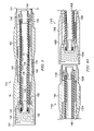
- FIG. 2 is an enlarged sectional side view of the preferred dual wall drill string pipe section shown in FIG. 1 .
- FIG. 3 is a sectional side view of an alternative embodiment of the dual wall drill string pipe section in accordance with the present invention.
- FIG. 4A is a sectional side view of a pair of the dual wall drill string pipe sections shown in FIG. 3 .
- FIG. 4B is a sectional side view of the pair of dual wall drill string pipe sections shown in FIG. 3 connected to each other.
- FIG. 5A is a cross-sectional view of a preferred embodiment of the flexible sleeve in accordance with the present invention.
- FIG. 5B is a cross-sectional view of an alternative embodiment of the flexible sleeve in accordance with the present invention.
- FIG. 6 is a sectional side view of a preferred dual wall drill string pipe section and a drilling mechanism.
- FIG. 7 is a sectional side view of an alternative embodiment of the dual wall drill string assembly partially in a subsurface borehole in accordance with the present invention.
- FIG. 8 is a sectional side view of an alternative embodiment of the dual wall drill string assembly partially in a subsurface borehole in accordance with the present invention.
- FIG. 1 illustrates a preferred embodiment of the dual wall drill string assembly partially in a subsurface borehole.
- the preferred dual wall drill string assembly is designated generally by reference numeral 10 and the subsurface borehole is designated by reference numeral 12 .
- the preferred drill string assembly may comprise a plurality of dual wall pipe sections 14 . It is contemplated, however, that the drill string assembly of the invention claimed herein may comprise a single dual wall pipe.
- the preferred drill string assembly may further comprise a drilling mechanism, an interchange sub, a means for conveying fluid under pressure, a signal source such as a transmitter or a source of electricity, a receiver, and a navigation transmitter as described in more detail below. It is further contemplated that the assembly may be used in connection with any suitable steering mechanism such as a bent sub or a deflectable drill bit as will be appreciated by one having ordinary skill in the art.
- the dual wall drill string assembly of the present invention is adapted for use in all subsurface drilling applications.
- a plurality of dual wall pipe sections 14 are connected together to produce a dual wall drill string.
- the preferred dual wall drill string comprising dual wall pipe sections 14 is connected to drilling mechanism 16 by interchange sub 18 .
- Drilling mechanism 16 is adapted to produce cuttings as it drills subsurface borehole 12 .
- Drilling mechanism 16 may be any suitable drilling mechanism adapted to drill a subsurface borehole such as a rotary cutter or a down-the-hole hammer.
- Interchange sub 18 is adapted to direct cuttings from the drilling mechanism to the dual wall drill string assembly. More particularly, as discussed below, interchange sub 18 directs cuttings and fluid under pressure from the subsurface borehole into the inner tube of the dual wall drill string.
- Interchange sub 18 may be any suitable device adapted to direct cuttings from the drilling mechanism to the dual wall drill string. Also, the interchange sub drilling mechanism or use of a separate interchange sub may have communication capabilities such as a location transmitter. It is also contemplated that the drill string assembly of the invention may not require an interchange sub because a channel through which cuttings may be transferred from the drilling mechanism to the drill string may be incorporated into the drilling mechanism.
- the preferred drill string assembly also includes a means for conveying fluid through the dual wall drill string towards the drilling mechanism such as pump 20 .
- pump 20 is adapted to convey fluid under pressure through an annular channel defined by the outer tube and the inner tube of the dual wall drill string towards drilling mechanism 16 .
- the flow of fluid from pump 20 through the annular channel of the dual wall drill string and, thereafter, through interchange sub 18 towards drilling mechanism 16 is designated by arrowed line 22 .
- the flow of cuttings and fluid from drilling mechanism 16 into interchange sub 18 and, thereafter, into the inner tube of the dual wall drill string is designated by arrowed lines 24 .
- the means for conveying fluid through the annular channel of the dual wall drill string toward the drilling mechanism may be any suitable means for conveying fluid under pressure.
- the preferred embodiment of the dual wall drill string assembly includes signal source of electricity 26 adapted to provide an electrical current to navigation transmitter 28 , which is adapted to indicate the direction of drilling mechanism 16 .
- Source of electricity 26 may be any suitable source for providing an electrical current.
- Navigation transmitter 28 may be any suitable device adapted to monitor the direction of the drilling mechanism.
- Pipe section 14 includes metallic outer tube 30 having outer tube first end 31 and outer tube second end 32 opposite the outer tube first end.
- drilling mechanism 16 (See FIG. 1 ) is located adjacent to outer tube first end 31 of a dual wall pipe section such as pipe section 14 .
- Outer tube first end 31 is adapted to be connected to the outer tube second end of another pipe section such that fluid may be conveyed under pressure in the outer tubes of the pipe sections.
- Outer tube second end 32 is adapted to be connected to the outer tube first end of another pipe section such that fluid may be conveyed under pressure in the outer tubes of the pipe sections.
- outer tube 30 of each dual wall pipe section 14 is rigid and includes a pair of threaded ends 33 and 34 adapted to be removably connected to a threaded end on another rigid outer tube section.
- the preferred dual wall pipe section 14 also includes flexible, substantially non-metallic inner tube 40 that is substantially enclosed within and generally coaxially aligned with outer tube 30 .
- Inner tube 40 includes inner tube first end 41 , inner tube second end 42 opposite the inner tube first end, and an inner tube inner diameter designated by line 43 .
- Inner tube first end 41 is adapted to be connected to the inner tube second end of another pipe section such that cuttings and fluid under pressure may be conveyed in the inner tubes of the pipe sections.
- Inner tube second end 42 is adapted to be connected to the inner tube first end of another pipe section such that cuttings and fluid under pressure may be conveyed in the inner tubes of the pipe sections.
- an inner tube such as inner tube 40 is adapted to convey cuttings from drilling mechanism 16 toward inner tube second end 42 .
- the drill string assembly is comprised of a plurality of pipe sections 14 , each of which includes a flexible inner tube section 40 , wherein each of the flexible inner tube sections has male connection end 44 and female connection end 45 .
- Each male connection end 44 is adapted to be connected to a female connection end on another flexible inner tube section and each female connection end 45 is adapted to be connected to a male connection end on another flexible inner tube section.
- each flexible inner tube section is in communication (as hereinafter described) with each adjacent flexible inner tube section.
- the preferred inner tube 40 also includes conductive element 46 for conveying a signal such as an electrical signal from source of electricity 26 (See FIG. 1 ) to drilling mechanism 16 (See FIG. 1 ).
- the signal may be used to indicate the direction of the drilling mechanism.
- conductive element 46 is continuous from inner tube first end 41 to inner tube second end 42 so that a continuous conductive path is provided from one end of the drill string to the other and provides an electrical current from the source of electricity to a navigation device. It is also preferred that conductive element 46 is substantially enclosed within inner tube 40 .
- conductive element 46 preferably comprises at least one metallic or fiber optic material. It is also preferred that conductive element 46 includes metallic wire, metallic mesh or thin wall pipe. It is contemplated within the scope of the invention, however, that conductive element 46 may be any suitable material for conveying a signal such as an electrical current.
- the preferred inner tube also includes a means for reinforcing the inner tube such as mesh 48 .
- Mesh 48 is adapted to provide structural support to the flexible, substantially non-metallic inner tube. More particularly, mesh 48 is adapted to enable inner tube 40 to withstand greater pressure differentials between the pressure in annular channel 50 and the pressure in the inner tube. In other words, mesh 48 provides the inner tube with resistance against collapsing when the pressure in the annular channel becomes significantly greater than the pressure in the inner tube, and resistance against bursting when the pressure in the inner tube becomes significantly greater than the pressure in the annular channel. In addition, mesh 48 is adapted to minimize the bending resistance of the inner tube. As a result, mesh 48 does not significantly impair the steerability of the drill string assembly.
- Mesh 48 may be made from wire mesh, fabric mesh, thin wall metallic tube or any other suitable material adapted to provide resistance against pressure differentials between the annular channel and the inner tube and minimize resistance against bending or steering the inner tube. It is contemplated that mesh 48 may be located throughout the inner tube or in designated areas. It is further contemplated that mesh 48 may be substantially enclosed within the inner tube, applied to the exterior or interior surfaces of the inner tube, or a combination thereof.
- outer tube 30 and inner tube 40 define annular channel 50 therebetween.
- the annular channel is adapted to convey fluid under pressure from the means for conveying fluid such as pump 20 (See FIG. 1 ) toward the inner tube first end. More particularly, annular channel 50 is adapted to convey drilling fluid under pressure from inner tube second end 42 toward inner tube first end 41 .
- the preferred dual wall pipe section 14 also includes at least one centering member such as flexible sleeve 60 that is located in annular channel 50 .
- at least one flexible sleeve 60 is adapted to maintain outer tube 30 and inner tube 40 in a substantially concentric relationship to each other.
- flexible sleeve 60 has at least one opening therein such as holes 262 (See FIG. 5A ).
- flexible sleeve 360 includes apertures 362 (See FIG. 5B ). It is also preferred that the cumulative area of the openings in the flexible sleeves is greater than the cross-sectional area defined by inner tube inner diameter 43 .
- FIG. 3 illustrates an alternative embodiment of a dual wall pipe section. More particularly, FIG. 3 illustrates an alternative embodiment of the male connection end and the female connection end of the flexible, substantially non-metallic inner tube of a dual wall pipe section.
- dual wall pipe section 114 includes metallic outer tube 130 having outer tube first end 131 and outer tube second end 132 opposite the outer tube first end.
- the outer tube also includes a pair of threaded connections 133 and 134 adapted to be connected to the threaded connections of another pipe section 114 .
- Pipe section 114 also includes flexible, substantially non-metallic inner tube 140 .
- Inner tube 140 includes inner tube first end 141 , inner tube second end 142 opposite the inner tube first end, and inner tube inner diameter designated by line 143 .
- Inner tube 140 also includes male connection end 144 and female connection end 145 which are adapted to be connected to the female connection end and the male connection end, respectively, of an inner tube of another pipe section such that adjacent pipe sections are in communication with each other, fluid can be conveyed under pressure through annular channel 150 , and cuttings and fluid under pressure can be conveyed in the inner tubes of the pipe sections.
- Inner tube 140 also includes conductive element 146 , stiffener 148 and flexible sleeves 160 . While stiffener 148 is shown on the outside surface of preferred inner tube 140 , it is contemplated within the scope of the invention that one or more stiffeners may be located on the inside surface of the inner tube or substantially or entirely enclosed within the inner tube.
- FIG. 4A shows a pair of pipe sections 114 A and 114 B in a nearly-connected relationship to each other.
- pipe section 114 A includes metallic outer tube 130 A having threaded end 133 A adapted to be connected to threaded end 134 B of outer tube 130 B of pipe section 114 B.
- Pipe section 114 A also includes flexible, substantially non-metallic inner tube 140 A.
- Inner tube 140 A includes male connection end 144 A which is adapted to be connected to female connection end 145 B of inner tube 140 B of pipe section 114 B.
- Male connection end 144 A and female connection end 145 B are adapted to be connected to each other such that inner tubes 140 A and 140 B are in communication with each other and cuttings and fluid under pressure can be conveyed through annular channels 150 A and 150 B of pipe sections 114 A and 114 B, respectively.
- FIG. 4B the preferred pipe sections shown in FIG. 4A are illustrated in connected relationship to each other. More particularly, threaded ends 133 A and 134 B of outer tubes 130 A and 130 B, respectively, are shown in full threaded engagement with each other.
- male connection end 144 A and female connection end 145 B of inner tubes 140 A and 140 B, respectively, are shown connected to each other such that inner tubes 140 A and 140 B are in communication with each other, fluid under pressure may be conveyed through annular channels 150 A and 150 B, and cuttings and fluid under pressure may be conveyed through the inner tubes 140 A and 140 B.
- preferred pipe section 214 includes outer tube 230 , inner tube 240 and flexible sleeve 260 .
- Flexible sleeve 260 includes a plurality of holes 262 . Holes 262 are adapted to permit fluid under pressure to be conveyed therethrough. It is contemplated that the cumulative area of holes 262 in flexible sleeve 260 may be greater than the cross-sectional area defined by inner tube inner diameter 264 . It is also contemplated that the cumulative area of holes 262 in flexible sleeve 260 may be less than or equal to the cross-sectional area defined by inner tube inner diameter 264 .
- preferred dual wall pipe section 314 includes outer tube 330 , inner tube 340 and flexible sleeve 360 .
- Flexible sleeve 360 includes a plurality of apertures 362 .
- Apertures 362 are adapted to permit fluid under pressure to be conveyed therethrough. It is contemplated that the cumulative area of apertures 362 in flexible sleeve 360 may be greater than the cross-sectional area defined by inner tube inner diameter 364 . It is also contemplated that the cumulative area of apertures 362 in flexible sleeve 360 may be less than or equal to the cross-sectional area defined by inner tube inner diameter 364 . While FIGS.
- FIGS. 5A and 5B illustrate flexible sleeve 260 having a plurality of round holes 262 and flexible sleeve 360 having a plurality of arched apertures 362 , respectively, it is contemplated within the scope of the invention that one or more openings of any suitable configuration and location may be provided in the flexible sleeves of the present invention.
- preferred dual wall pipe section 14 is illustrated in a nearly-connected relationship to interchange sub 18 .
- Preferred pipe section 14 is illustrated in FIGS. 1 and 2 and described in detail above.
- threaded end 33 is adapted to be connected to threaded end 66 of interchange sub 18 .
- Drilling mechanism 16 includes navigation transmitter 28 , cutting head 68 , fluid channel 70 , and cuttings channel 72 .
- Drilling head 68 is adapted to drill a subsurface borehole as illustrated in FIG. 1 .
- Drilling head 68 may be any suitable mechanism for drilling a subsurface borehole.
- Fluid channel 70 is adapted to convey fluid under pressure from annular channel 50 of pipe section 14 to drilling head 68 of drilling mechanism 16 .
- Fluid channel 70 may be of any suitable conventional configuration adapted to convey fluid under pressure toward the drilling head of the drilling mechanism.
- Cuttings channel 72 is adapted to convey cuttings produced by the drilling head of the drilling mechanism from the subsurface borehole to inner tube 40 of pipe section 14 .
- Cuttings channel 72 on interchange sub 18 may be of any suitable configuration for conveying cuttings from the drilling mechanism to the inner tube of one or more dual wall pipe sections.
- FIG. 7 illustrates a preferred dual wall drill string assembly utilizing a drilling mechanism commonly known as a down-the-hole percussion hammer.
- preferred assembly 400 includes a plurality of dual wall pipe sections 414 connected to each other.
- the drill string of dual wall pipe sections 414 is connected to drilling mechanism 416 by interchange sub 418 .
- Drilling mechanism 416 is adapted to drill subsurface borehole 412 .
- Interchange sub 418 is adapted to convey cuttings from drilling mechanism 416 to inner tubes 440 of pipe sections 414 .
- FIG. 8 illustrates a preferred dual wall string assembly without an interchange sub.
- preferred assembly 500 includes dual wall pipe section 514 which is connected directly to drilling mechanism 516 .
- Drilling mechanism 516 is adapted to drill subsurface borehole 512 .
- Drilling mechanism 516 includes cuttings channel 519 which is adapted to convey cuttings from the drilling mechanism to the dual wall pipe section.
- the dual wall drill string assembly of the present invention In operation, several advantages of the dual wall drill string assembly of the present invention are achieved.
- a borehole is drilled by the drilling mechanism.
- the cuttings produced by the drilling mechanism are conveyed to the inside of the flexible, substantially non-metallic inner tube of the dual wall drill string as fluid under pressure is conveyed through the annular channel of the dual wall drill string toward the drilling mechanism.
- the dual wall drill string assembly of the invention claimed herein is adapted for use in all subsurface drilling applications.
- the flexible, substantially non-metallic inner tube of the dual wall drill string assembly of the present invention permits the assembly to be used in all subsurface drilling applications because the inner tube is flexible and transmits considerably less bending resistance to the outer tube.
- the flexible, substantially non-metallic inner tube is adapted to substantially enclose a conductive element for conveying a signal to the navigation transmitter. Consequently, the direction of the drilling mechanism can be monitored, and short circuiting of the conductive element on the metallic outer tube is avoided.
- Flexible sleeves also contribute to the ability of the preferred embodiment of the dual wall drill assembly of the present invention to function in any subsurface drilling application(s).
- the dual wall drill string assembly is capable of reaming the arcuate path of a borehole in any subsurface drilling application(s). Still further, the assembly is capable of pulling or pushing a product such as pipeline, ducts and the like into the arcuate path of a subsurface borehole.
Abstract
Description
Claims (19)
Priority Applications (2)
| Application Number | Priority Date | Filing Date | Title |
|---|---|---|---|
| US10/712,324 US7134514B2 (en) | 2003-11-13 | 2003-11-13 | Dual wall drill string assembly |
| US10/972,885 US7152700B2 (en) | 2003-11-13 | 2004-10-25 | Dual wall drill string assembly |
Applications Claiming Priority (1)
| Application Number | Priority Date | Filing Date | Title |
|---|---|---|---|
| US10/712,324 US7134514B2 (en) | 2003-11-13 | 2003-11-13 | Dual wall drill string assembly |
Related Child Applications (1)
| Application Number | Title | Priority Date | Filing Date |
|---|---|---|---|
| US10/972,885 Continuation-In-Part US7152700B2 (en) | 2003-11-13 | 2004-10-25 | Dual wall drill string assembly |
Publications (2)
| Publication Number | Publication Date |
|---|---|
| US20050284664A1 US20050284664A1 (en) | 2005-12-29 |
| US7134514B2 true US7134514B2 (en) | 2006-11-14 |
Family
ID=34573529
Family Applications (1)
| Application Number | Title | Priority Date | Filing Date |
|---|---|---|---|
| US10/712,324 Expired - Lifetime US7134514B2 (en) | 2003-11-13 | 2003-11-13 | Dual wall drill string assembly |
Country Status (1)
| Country | Link |
|---|---|
| US (1) | US7134514B2 (en) |
Cited By (33)
| Publication number | Priority date | Publication date | Assignee | Title |
|---|---|---|---|---|
| US20080217066A1 (en) * | 2007-03-07 | 2008-09-11 | Barbera James S | Lubricated pilot tubes for use with auger boring machine pilot steering system |
| US8424617B2 (en) | 2008-08-20 | 2013-04-23 | Foro Energy Inc. | Methods and apparatus for delivering high power laser energy to a surface |
| US8571368B2 (en) | 2010-07-21 | 2013-10-29 | Foro Energy, Inc. | Optical fiber configurations for transmission of laser energy over great distances |
| US8627901B1 (en) | 2009-10-01 | 2014-01-14 | Foro Energy, Inc. | Laser bottom hole assembly |
| US8662160B2 (en) | 2008-08-20 | 2014-03-04 | Foro Energy Inc. | Systems and conveyance structures for high power long distance laser transmission |
| US9027668B2 (en) | 2008-08-20 | 2015-05-12 | Foro Energy, Inc. | Control system for high power laser drilling workover and completion unit |
| US9074422B2 (en) | 2011-02-24 | 2015-07-07 | Foro Energy, Inc. | Electric motor for laser-mechanical drilling |
| US9080425B2 (en) | 2008-10-17 | 2015-07-14 | Foro Energy, Inc. | High power laser photo-conversion assemblies, apparatuses and methods of use |
| US9089928B2 (en) | 2008-08-20 | 2015-07-28 | Foro Energy, Inc. | Laser systems and methods for the removal of structures |
| US9138786B2 (en) | 2008-10-17 | 2015-09-22 | Foro Energy, Inc. | High power laser pipeline tool and methods of use |
| US9242309B2 (en) | 2012-03-01 | 2016-01-26 | Foro Energy Inc. | Total internal reflection laser tools and methods |
| US9244235B2 (en) | 2008-10-17 | 2016-01-26 | Foro Energy, Inc. | Systems and assemblies for transferring high power laser energy through a rotating junction |
| US9267330B2 (en) | 2008-08-20 | 2016-02-23 | Foro Energy, Inc. | Long distance high power optical laser fiber break detection and continuity monitoring systems and methods |
| US9328558B2 (en) | 2013-11-13 | 2016-05-03 | Varel International Ind., L.P. | Coating of the piston for a rotating percussion system in downhole drilling |
| US9347271B2 (en) | 2008-10-17 | 2016-05-24 | Foro Energy, Inc. | Optical fiber cable for transmission of high power laser energy over great distances |
| US9360643B2 (en) | 2011-06-03 | 2016-06-07 | Foro Energy, Inc. | Rugged passively cooled high power laser fiber optic connectors and methods of use |
| US9360631B2 (en) | 2008-08-20 | 2016-06-07 | Foro Energy, Inc. | Optics assembly for high power laser tools |
| US9404342B2 (en) | 2013-11-13 | 2016-08-02 | Varel International Ind., L.P. | Top mounted choke for percussion tool |
| US9415496B2 (en) | 2013-11-13 | 2016-08-16 | Varel International Ind., L.P. | Double wall flow tube for percussion tool |
| US9562392B2 (en) | 2013-11-13 | 2017-02-07 | Varel International Ind., L.P. | Field removable choke for mounting in the piston of a rotary percussion tool |
| US9562395B2 (en) | 2008-08-20 | 2017-02-07 | Foro Energy, Inc. | High power laser-mechanical drilling bit and methods of use |
| US9664012B2 (en) | 2008-08-20 | 2017-05-30 | Foro Energy, Inc. | High power laser decomissioning of multistring and damaged wells |
| US9669492B2 (en) | 2008-08-20 | 2017-06-06 | Foro Energy, Inc. | High power laser offshore decommissioning tool, system and methods of use |
| US9719302B2 (en) | 2008-08-20 | 2017-08-01 | Foro Energy, Inc. | High power laser perforating and laser fracturing tools and methods of use |
| US9856706B2 (en) | 2012-06-05 | 2018-01-02 | Halliburton Energy Services, Inc. | Methods and systems for performance of subterranean operations using dual string pipes |
| US10221687B2 (en) | 2015-11-26 | 2019-03-05 | Merger Mines Corporation | Method of mining using a laser |
| US10246954B2 (en) | 2015-01-13 | 2019-04-02 | Saudi Arabian Oil Company | Drilling apparatus and methods for reducing circulation loss |
| US10260295B2 (en) | 2017-05-26 | 2019-04-16 | Saudi Arabian Oil Company | Mitigating drilling circulation loss |
| US10301912B2 (en) * | 2008-08-20 | 2019-05-28 | Foro Energy, Inc. | High power laser flow assurance systems, tools and methods |
| US10407996B2 (en) | 2017-05-03 | 2019-09-10 | Hunting Energy Services, Inc. | One piece forged fluidic displacement drill pipe and method of manufacture thereof |
| US11149509B2 (en) | 2019-12-17 | 2021-10-19 | Saudi Arabian Oil Company | Trojan drill pipe |
| US20220162916A1 (en) * | 2019-04-04 | 2022-05-26 | Ducon - Becker Service Technology, Llc. | Manufacturing methods for dual concentric tubing |
| US11746936B2 (en) | 2018-12-28 | 2023-09-05 | Halliburton Energy Services, Inc. | Threaded joint for coupling two concentric tubes to one tube |
Families Citing this family (5)
| Publication number | Priority date | Publication date | Assignee | Title |
|---|---|---|---|---|
| WO2009088935A1 (en) | 2008-01-02 | 2009-07-16 | Zupanick Joseph A | Slim-hole parasite string |
| US10428634B2 (en) * | 2015-09-30 | 2019-10-01 | Islander, LLC | Water jet mining system and method |
| CN105484666B (en) * | 2016-01-06 | 2018-11-02 | 无锡凯通钻具有限公司 | A kind of double-wall drill pipe drives the guiding forward method of full geosteering drill bit |
| CN111810084A (en) * | 2020-06-12 | 2020-10-23 | 煤科集团沈阳研究院有限公司 | Coal bed mesh gas extraction drilling construction method of water jet drilling machine |
| CN113389499B (en) * | 2021-07-20 | 2024-03-22 | 中煤科工集团重庆研究院有限公司 | Double-wall drill rod and processing method thereof |
Citations (25)
| Publication number | Priority date | Publication date | Assignee | Title |
|---|---|---|---|---|
| US2494803A (en) * | 1946-08-22 | 1950-01-17 | Frost Jack | Multiple passage pipe sections for oil well drills or the like |
| US2537605A (en) | 1947-08-07 | 1951-01-09 | Standard Oil Dev Co | Drilling bore holes |
| US3065807A (en) * | 1958-06-30 | 1962-11-27 | Gas Drilling Services Co | Dual passage well drilling pipe |
| US3265091A (en) | 1962-12-07 | 1966-08-09 | Jarnett Frank D De | Fluid-packed drill pipe |
| US3471177A (en) * | 1967-01-03 | 1969-10-07 | Smith International | Dual drill pipe |
| US3638970A (en) * | 1968-02-12 | 1972-02-01 | Becker Drilling Alberta Ltd | Joint for double-walled drill pipe |
| US3786878A (en) | 1970-08-25 | 1974-01-22 | H Sherman | Dual concentric drillpipe |
| US3830319A (en) * | 1972-05-16 | 1974-08-20 | Stork Conrad Bv | Drilling apparatus |
| US4067596A (en) * | 1976-08-25 | 1978-01-10 | Smith International, Inc. | Dual flow passage drill stem |
| US4149739A (en) * | 1977-03-18 | 1979-04-17 | Summa Corporation | Dual passage pipe for cycling water to an undersea mineral aggregate gathering apparatus |
| US4280535A (en) * | 1978-01-25 | 1981-07-28 | Walker-Neer Mfg. Co., Inc. | Inner tube assembly for dual conduit drill pipe |
| US4484641A (en) | 1981-05-21 | 1984-11-27 | Dismukes Newton B | Tubulars for curved bore holes |
| USRE32267E (en) | 1979-09-24 | 1986-10-21 | Reading & Bates Construction Co. | Process for drilling underground arcuate paths and installing production casings, conduits, or flow pipes therein |
| US4732223A (en) | 1984-06-12 | 1988-03-22 | Universal Downhole Controls, Ltd. | Controllable downhole directional drilling tool |
| US4940098A (en) | 1989-05-26 | 1990-07-10 | Moss Daniel H | Reverse circulation drill rod |
| US4997048A (en) | 1989-08-24 | 1991-03-05 | Isom John R | Drill pipe assemblies |
| US5269384A (en) | 1991-11-08 | 1993-12-14 | Cherrington Corporation | Method and apparatus for cleaning a bore hole |
| US5467832A (en) | 1992-01-21 | 1995-11-21 | Schlumberger Technology Corporation | Method for directionally drilling a borehole |
| US5713423A (en) | 1992-07-24 | 1998-02-03 | The Charles Machine Works, Inc. | Drill pipe |
| US6296066B1 (en) | 1997-10-27 | 2001-10-02 | Halliburton Energy Services, Inc. | Well system |
| US6364038B1 (en) | 2000-04-21 | 2002-04-02 | W B Driver | Downhole flexible drive system |
| US6367564B1 (en) | 1999-09-24 | 2002-04-09 | Vermeer Manufacturing Company | Apparatus and method for providing electrical transmission of power and signals in a directional drilling apparatus |
| US6388577B1 (en) | 1997-04-07 | 2002-05-14 | Kenneth J. Carstensen | High impact communication and control system |
| US20020084109A1 (en) | 2000-07-31 | 2002-07-04 | Randy Runquist | Steerable fluid hammer |
| US6443244B1 (en) | 2000-06-30 | 2002-09-03 | Marathon Oil Company | Buoyant drill pipe, drilling method and drilling system for subterranean wells |
Family Cites Families (1)
| Publication number | Priority date | Publication date | Assignee | Title |
|---|---|---|---|---|
| US5629384A (en) * | 1994-05-17 | 1997-05-13 | Consiglio Nazionale Delle Ricerche | Polymers of N-acryloylmorpholine activated at one end and conjugates with bioactive materials and surfaces |
-
2003
- 2003-11-13 US US10/712,324 patent/US7134514B2/en not_active Expired - Lifetime
Patent Citations (25)
| Publication number | Priority date | Publication date | Assignee | Title |
|---|---|---|---|---|
| US2494803A (en) * | 1946-08-22 | 1950-01-17 | Frost Jack | Multiple passage pipe sections for oil well drills or the like |
| US2537605A (en) | 1947-08-07 | 1951-01-09 | Standard Oil Dev Co | Drilling bore holes |
| US3065807A (en) * | 1958-06-30 | 1962-11-27 | Gas Drilling Services Co | Dual passage well drilling pipe |
| US3265091A (en) | 1962-12-07 | 1966-08-09 | Jarnett Frank D De | Fluid-packed drill pipe |
| US3471177A (en) * | 1967-01-03 | 1969-10-07 | Smith International | Dual drill pipe |
| US3638970A (en) * | 1968-02-12 | 1972-02-01 | Becker Drilling Alberta Ltd | Joint for double-walled drill pipe |
| US3786878A (en) | 1970-08-25 | 1974-01-22 | H Sherman | Dual concentric drillpipe |
| US3830319A (en) * | 1972-05-16 | 1974-08-20 | Stork Conrad Bv | Drilling apparatus |
| US4067596A (en) * | 1976-08-25 | 1978-01-10 | Smith International, Inc. | Dual flow passage drill stem |
| US4149739A (en) * | 1977-03-18 | 1979-04-17 | Summa Corporation | Dual passage pipe for cycling water to an undersea mineral aggregate gathering apparatus |
| US4280535A (en) * | 1978-01-25 | 1981-07-28 | Walker-Neer Mfg. Co., Inc. | Inner tube assembly for dual conduit drill pipe |
| USRE32267E (en) | 1979-09-24 | 1986-10-21 | Reading & Bates Construction Co. | Process for drilling underground arcuate paths and installing production casings, conduits, or flow pipes therein |
| US4484641A (en) | 1981-05-21 | 1984-11-27 | Dismukes Newton B | Tubulars for curved bore holes |
| US4732223A (en) | 1984-06-12 | 1988-03-22 | Universal Downhole Controls, Ltd. | Controllable downhole directional drilling tool |
| US4940098A (en) | 1989-05-26 | 1990-07-10 | Moss Daniel H | Reverse circulation drill rod |
| US4997048A (en) | 1989-08-24 | 1991-03-05 | Isom John R | Drill pipe assemblies |
| US5269384A (en) | 1991-11-08 | 1993-12-14 | Cherrington Corporation | Method and apparatus for cleaning a bore hole |
| US5467832A (en) | 1992-01-21 | 1995-11-21 | Schlumberger Technology Corporation | Method for directionally drilling a borehole |
| US5713423A (en) | 1992-07-24 | 1998-02-03 | The Charles Machine Works, Inc. | Drill pipe |
| US6388577B1 (en) | 1997-04-07 | 2002-05-14 | Kenneth J. Carstensen | High impact communication and control system |
| US6296066B1 (en) | 1997-10-27 | 2001-10-02 | Halliburton Energy Services, Inc. | Well system |
| US6367564B1 (en) | 1999-09-24 | 2002-04-09 | Vermeer Manufacturing Company | Apparatus and method for providing electrical transmission of power and signals in a directional drilling apparatus |
| US6364038B1 (en) | 2000-04-21 | 2002-04-02 | W B Driver | Downhole flexible drive system |
| US6443244B1 (en) | 2000-06-30 | 2002-09-03 | Marathon Oil Company | Buoyant drill pipe, drilling method and drilling system for subterranean wells |
| US20020084109A1 (en) | 2000-07-31 | 2002-07-04 | Randy Runquist | Steerable fluid hammer |
Cited By (50)
| Publication number | Priority date | Publication date | Assignee | Title |
|---|---|---|---|---|
| US20080217066A1 (en) * | 2007-03-07 | 2008-09-11 | Barbera James S | Lubricated pilot tubes for use with auger boring machine pilot steering system |
| US7614461B2 (en) * | 2007-03-07 | 2009-11-10 | Barbera James S | Lubricated pilot tubes for use with auger boring machine pilot steering system and use thereof |
| US9284783B1 (en) | 2008-08-20 | 2016-03-15 | Foro Energy, Inc. | High power laser energy distribution patterns, apparatus and methods for creating wells |
| US11060378B2 (en) * | 2008-08-20 | 2021-07-13 | Foro Energy, Inc. | High power laser flow assurance systems, tools and methods |
| US8636085B2 (en) | 2008-08-20 | 2014-01-28 | Foro Energy, Inc. | Methods and apparatus for removal and control of material in laser drilling of a borehole |
| US8662160B2 (en) | 2008-08-20 | 2014-03-04 | Foro Energy Inc. | Systems and conveyance structures for high power long distance laser transmission |
| US8701794B2 (en) | 2008-08-20 | 2014-04-22 | Foro Energy, Inc. | High power laser perforating tools and systems |
| US8757292B2 (en) | 2008-08-20 | 2014-06-24 | Foro Energy, Inc. | Methods for enhancing the efficiency of creating a borehole using high power laser systems |
| US8820434B2 (en) | 2008-08-20 | 2014-09-02 | Foro Energy, Inc. | Apparatus for advancing a wellbore using high power laser energy |
| US8826973B2 (en) | 2008-08-20 | 2014-09-09 | Foro Energy, Inc. | Method and system for advancement of a borehole using a high power laser |
| US8869914B2 (en) | 2008-08-20 | 2014-10-28 | Foro Energy, Inc. | High power laser workover and completion tools and systems |
| US8936108B2 (en) | 2008-08-20 | 2015-01-20 | Foro Energy, Inc. | High power laser downhole cutting tools and systems |
| US8997894B2 (en) | 2008-08-20 | 2015-04-07 | Foro Energy, Inc. | Method and apparatus for delivering high power laser energy over long distances |
| US9027668B2 (en) | 2008-08-20 | 2015-05-12 | Foro Energy, Inc. | Control system for high power laser drilling workover and completion unit |
| US8511401B2 (en) | 2008-08-20 | 2013-08-20 | Foro Energy, Inc. | Method and apparatus for delivering high power laser energy over long distances |
| US9562395B2 (en) | 2008-08-20 | 2017-02-07 | Foro Energy, Inc. | High power laser-mechanical drilling bit and methods of use |
| US8424617B2 (en) | 2008-08-20 | 2013-04-23 | Foro Energy Inc. | Methods and apparatus for delivering high power laser energy to a surface |
| US10301912B2 (en) * | 2008-08-20 | 2019-05-28 | Foro Energy, Inc. | High power laser flow assurance systems, tools and methods |
| US9360631B2 (en) | 2008-08-20 | 2016-06-07 | Foro Energy, Inc. | Optics assembly for high power laser tools |
| US9089928B2 (en) | 2008-08-20 | 2015-07-28 | Foro Energy, Inc. | Laser systems and methods for the removal of structures |
| US9664012B2 (en) | 2008-08-20 | 2017-05-30 | Foro Energy, Inc. | High power laser decomissioning of multistring and damaged wells |
| US10036232B2 (en) | 2008-08-20 | 2018-07-31 | Foro Energy | Systems and conveyance structures for high power long distance laser transmission |
| US9669492B2 (en) | 2008-08-20 | 2017-06-06 | Foro Energy, Inc. | High power laser offshore decommissioning tool, system and methods of use |
| US9267330B2 (en) | 2008-08-20 | 2016-02-23 | Foro Energy, Inc. | Long distance high power optical laser fiber break detection and continuity monitoring systems and methods |
| US9719302B2 (en) | 2008-08-20 | 2017-08-01 | Foro Energy, Inc. | High power laser perforating and laser fracturing tools and methods of use |
| US9244235B2 (en) | 2008-10-17 | 2016-01-26 | Foro Energy, Inc. | Systems and assemblies for transferring high power laser energy through a rotating junction |
| US9138786B2 (en) | 2008-10-17 | 2015-09-22 | Foro Energy, Inc. | High power laser pipeline tool and methods of use |
| US9347271B2 (en) | 2008-10-17 | 2016-05-24 | Foro Energy, Inc. | Optical fiber cable for transmission of high power laser energy over great distances |
| US9327810B2 (en) | 2008-10-17 | 2016-05-03 | Foro Energy, Inc. | High power laser ROV systems and methods for treating subsea structures |
| US9080425B2 (en) | 2008-10-17 | 2015-07-14 | Foro Energy, Inc. | High power laser photo-conversion assemblies, apparatuses and methods of use |
| US8627901B1 (en) | 2009-10-01 | 2014-01-14 | Foro Energy, Inc. | Laser bottom hole assembly |
| US8879876B2 (en) | 2010-07-21 | 2014-11-04 | Foro Energy, Inc. | Optical fiber configurations for transmission of laser energy over great distances |
| US8571368B2 (en) | 2010-07-21 | 2013-10-29 | Foro Energy, Inc. | Optical fiber configurations for transmission of laser energy over great distances |
| US9074422B2 (en) | 2011-02-24 | 2015-07-07 | Foro Energy, Inc. | Electric motor for laser-mechanical drilling |
| US9784037B2 (en) | 2011-02-24 | 2017-10-10 | Daryl L. Grubb | Electric motor for laser-mechanical drilling |
| US9360643B2 (en) | 2011-06-03 | 2016-06-07 | Foro Energy, Inc. | Rugged passively cooled high power laser fiber optic connectors and methods of use |
| US9242309B2 (en) | 2012-03-01 | 2016-01-26 | Foro Energy Inc. | Total internal reflection laser tools and methods |
| US9856706B2 (en) | 2012-06-05 | 2018-01-02 | Halliburton Energy Services, Inc. | Methods and systems for performance of subterranean operations using dual string pipes |
| US9404342B2 (en) | 2013-11-13 | 2016-08-02 | Varel International Ind., L.P. | Top mounted choke for percussion tool |
| US9415496B2 (en) | 2013-11-13 | 2016-08-16 | Varel International Ind., L.P. | Double wall flow tube for percussion tool |
| US9562392B2 (en) | 2013-11-13 | 2017-02-07 | Varel International Ind., L.P. | Field removable choke for mounting in the piston of a rotary percussion tool |
| US9328558B2 (en) | 2013-11-13 | 2016-05-03 | Varel International Ind., L.P. | Coating of the piston for a rotating percussion system in downhole drilling |
| US10246954B2 (en) | 2015-01-13 | 2019-04-02 | Saudi Arabian Oil Company | Drilling apparatus and methods for reducing circulation loss |
| US10221687B2 (en) | 2015-11-26 | 2019-03-05 | Merger Mines Corporation | Method of mining using a laser |
| US10407996B2 (en) | 2017-05-03 | 2019-09-10 | Hunting Energy Services, Inc. | One piece forged fluidic displacement drill pipe and method of manufacture thereof |
| US10260295B2 (en) | 2017-05-26 | 2019-04-16 | Saudi Arabian Oil Company | Mitigating drilling circulation loss |
| US11448021B2 (en) | 2017-05-26 | 2022-09-20 | Saudi Arabian Oil Company | Mitigating drilling circulation loss |
| US11746936B2 (en) | 2018-12-28 | 2023-09-05 | Halliburton Energy Services, Inc. | Threaded joint for coupling two concentric tubes to one tube |
| US20220162916A1 (en) * | 2019-04-04 | 2022-05-26 | Ducon - Becker Service Technology, Llc. | Manufacturing methods for dual concentric tubing |
| US11149509B2 (en) | 2019-12-17 | 2021-10-19 | Saudi Arabian Oil Company | Trojan drill pipe |
Also Published As
| Publication number | Publication date |
|---|---|
| US20050284664A1 (en) | 2005-12-29 |
Similar Documents
| Publication | Publication Date | Title |
|---|---|---|
| US7134514B2 (en) | Dual wall drill string assembly | |
| US7152700B2 (en) | Dual wall drill string assembly | |
| US6863137B2 (en) | Well system | |
| AU777129B2 (en) | Inflatable packer with feed-thru conduits | |
| US6923273B2 (en) | Well system | |
| US7048061B2 (en) | Screen assembly with flow through connectors | |
| CN105637170B (en) | Directional drilling method and guided drilling system | |
| WO2016081155A1 (en) | Method for drilling extended reach lateral wellbores | |
| US6868913B2 (en) | Apparatus and methods for installing casing in a borehole | |
| US11661806B2 (en) | Downhole valve spanning a tool joint and methods of making and using same | |
| GB2438718A (en) | A steerable well drilling system | |
| US6318480B1 (en) | Drilling of laterals from a wellbore | |
| CA2521287C (en) | Dual wall drill string assembly | |
| US10822942B2 (en) | Telemetry system including a super conductor for a resource exploration and recovery system | |
| US8590615B2 (en) | Casing device | |
| US20080314644A1 (en) | Device for a Borehole Arrangement | |
| US9828826B2 (en) | Wellbore isolation system with communication lines | |
| US20230235641A1 (en) | Hydraulically driven cement downhole mixing enhancer apparatus | |
| EP3097249B1 (en) | Wired pipe erosion reduction | |
| US20210010346A1 (en) | Hybrid Coiled Tubing System | |
| NO20180235A1 (en) | A method and apparatus for simultaneously drilling and in-situ casing installation | |
| BR112019026851B1 (en) | PACKER, AND, SYSTEM AND METHOD FOR PROVIDING FLUID FLOW TO A WELL BORE | |
| GB2589815A (en) | Telemetry safety & life of well monitoring system | |
| WO2017222679A1 (en) | Wellbore isolation system with communication lines |
Legal Events
| Date | Code | Title | Description |
|---|---|---|---|
| AS | Assignment |
Owner name: TORQUELOCK CORPORATION, TEXAS Free format text: ASSIGNMENT OF ASSIGNORS INTEREST;ASSIGNOR:CHURCH, KRIS L.;REEL/FRAME:014711/0163 Effective date: 20031111 Owner name: AMERICAN AUGERS, INC., OHIO Free format text: ASSIGNMENT OF ASSIGNORS INTEREST;ASSIGNOR:RIEL, WILLIAM G.;REEL/FRAME:014711/0229 Effective date: 20031110 |
|
| STCF | Information on status: patent grant |
Free format text: PATENTED CASE |
|
| FPAY | Fee payment |
Year of fee payment: 4 |
|
| FPAY | Fee payment |
Year of fee payment: 8 |
|
| AS | Assignment |
Owner name: U. S. STEEL TUBULAR PRODUCTS, INC., PENNSYLVANIA Free format text: ASSIGNMENT OF ASSIGNORS INTEREST;ASSIGNOR:TORQUELOCK CORPORATION;REEL/FRAME:034206/0724 Effective date: 20141031 |
|
| MAFP | Maintenance fee payment |
Free format text: PAYMENT OF MAINTENANCE FEE, 12TH YEAR, LARGE ENTITY (ORIGINAL EVENT CODE: M1553) Year of fee payment: 12 |
|
| AS | Assignment |
Owner name: U.S. BANK NATIONAL ASSOCIATION, AS COLLATERAL AGENT, PENNSYLVANIA Free format text: SECURITY INTEREST;ASSIGNORS:UNITED STATES STEEL CORPORATION;U. S. STEEL TUBULAR PRODUCTS, INC.;REEL/FRAME:052790/0364 Effective date: 20200529 |
|
| AS | Assignment |
Owner name: U. S. STEEL TUBULAR PRODUCTS, INC., PENNSYLVANIA Free format text: RELEASE BY SECURED PARTY;ASSIGNOR:U.S. BANK NATIONAL ASSOCIATION, AS COLLATERAL AGENT;REEL/FRAME:055782/0355 Effective date: 20210329 Owner name: UNITED STATES STEEL CORPORATION, PENNSYLVANIA Free format text: RELEASE BY SECURED PARTY;ASSIGNOR:U.S. BANK NATIONAL ASSOCIATION, AS COLLATERAL AGENT;REEL/FRAME:055782/0355 Effective date: 20210329 |