US7124642B2 - Dual gauge with dual calibration system and method - Google Patents

Dual gauge with dual calibration system and method Download PDF

Info

Publication number
US7124642B2
US7124642B2 US11/107,388 US10738805A US7124642B2 US 7124642 B2 US7124642 B2 US 7124642B2 US 10738805 A US10738805 A US 10738805A US 7124642 B2 US7124642 B2 US 7124642B2
Authority
US
United States
Prior art keywords
coupled
bourdon tube
dial face
pointer
shaft
Prior art date
Legal status (The legal status is an assumption and is not a legal conclusion. Google has not performed a legal analysis and makes no representation as to the accuracy of the status listed.)
Active
Application number
US11/107,388
Other versions
US20060096382A1 (en
Inventor
Sidney R. Campbell
Tyler R. M. Kope
Current Assignee (The listed assignees may be inaccurate. Google has not performed a legal analysis and makes no representation or warranty as to the accuracy of the list.)
RIGHT WEIGH Inc
Original Assignee
RIGHT WEIGH Inc
Priority date (The priority date is an assumption and is not a legal conclusion. Google has not performed a legal analysis and makes no representation as to the accuracy of the date listed.)
Filing date
Publication date
Application filed by RIGHT WEIGH Inc filed Critical RIGHT WEIGH Inc
Priority to US11/107,388 priority Critical patent/US7124642B2/en
Assigned to RIGHT WEIGH, INC. reassignment RIGHT WEIGH, INC. ASSIGNMENT OF ASSIGNORS INTEREST (SEE DOCUMENT FOR DETAILS). Assignors: KOPE, TYLER R.M., CAMPBELL, SIDNEY R.
Publication of US20060096382A1 publication Critical patent/US20060096382A1/en
Application granted granted Critical
Publication of US7124642B2 publication Critical patent/US7124642B2/en
Active legal-status Critical Current
Anticipated expiration legal-status Critical

Links

Images

Classifications

    • GPHYSICS
    • G01MEASURING; TESTING
    • G01LMEASURING FORCE, STRESS, TORQUE, WORK, MECHANICAL POWER, MECHANICAL EFFICIENCY, OR FLUID PRESSURE
    • G01L7/00Measuring the steady or quasi-steady pressure of a fluid or a fluent solid material by mechanical or fluid pressure-sensitive elements
    • G01L7/02Measuring the steady or quasi-steady pressure of a fluid or a fluent solid material by mechanical or fluid pressure-sensitive elements in the form of elastically-deformable gauges
    • G01L7/04Measuring the steady or quasi-steady pressure of a fluid or a fluent solid material by mechanical or fluid pressure-sensitive elements in the form of elastically-deformable gauges in the form of flexible, deformable tubes, e.g. Bourdon gauges
    • G01L7/043Measuring the steady or quasi-steady pressure of a fluid or a fluent solid material by mechanical or fluid pressure-sensitive elements in the form of elastically-deformable gauges in the form of flexible, deformable tubes, e.g. Bourdon gauges with mechanical transmitting or indicating means
    • GPHYSICS
    • G01MEASURING; TESTING
    • G01LMEASURING FORCE, STRESS, TORQUE, WORK, MECHANICAL POWER, MECHANICAL EFFICIENCY, OR FLUID PRESSURE
    • G01L7/00Measuring the steady or quasi-steady pressure of a fluid or a fluent solid material by mechanical or fluid pressure-sensitive elements
    • G01L7/02Measuring the steady or quasi-steady pressure of a fluid or a fluent solid material by mechanical or fluid pressure-sensitive elements in the form of elastically-deformable gauges
    • G01L7/04Measuring the steady or quasi-steady pressure of a fluid or a fluent solid material by mechanical or fluid pressure-sensitive elements in the form of elastically-deformable gauges in the form of flexible, deformable tubes, e.g. Bourdon gauges
    • G01L7/048Measuring the steady or quasi-steady pressure of a fluid or a fluent solid material by mechanical or fluid pressure-sensitive elements in the form of elastically-deformable gauges in the form of flexible, deformable tubes, e.g. Bourdon gauges correcting or regulating means for flexible, deformable tubes

Definitions

  • the present invention is directed generally to gauges and, more particularly, to mechanical gauges.
  • a mechanical pressure gauge can be used to measure pressure of a contained gas.
  • a pointer is used in the gauge to point to a particular pressure value demarcation on a dial face to indicate present pressure of the contained gas.
  • a Bourdon tube can be used since it is constructed to assume a particular shape supported by pressurized gas inside the Bourdon tube. The Bourdon tube is gaseously coupled to the contained gas so is pressurized at the same pressure of the contained gas. If the pointer is mechanically coupled to the Bourdon tube so that movement of the pointer will properly indicate on the dial face pressure changes of the contained gas, then the pointer need only be positioned on the dial face according to one known pressure reading of the contained gas in order for the gauge to be calibrated and deemed accurate.
  • Some gauges conventionally known as dual gauges, use two Bourdon tubes each mechanically coupled to a separate pointer so that the two pointers of a dual gauge share a common dial face. Unfortunately, these conventional dual gauges are unable to provide a calibration function for both of their pointers.
  • FIG. 1 is an exploded isometric view of a conventional single pointer gauge having one Bourdon tube.
  • FIG. 2 is an isometric view of a shaft with cam used for calibration of the conventional single pointer gauge of FIG. 1 .
  • FIG. 3 is an isometric view of the shaft with cam of FIG. 2 better showing the cam.
  • FIG. 4 is an isometric view of a dial face of a dual pointer gauge with dual calibration.
  • FIG. 5 is an exploded isometric view of a first section of components associated with a first support of the dual gauge of FIG. 4 .
  • FIG. 6 is an isometric view of the first section of components shown in FIG. 5 as assembled.
  • FIG. 7 is an exploded isometric view of a second section of components associated with a second support of the dual gauge of FIG. 4 .
  • FIG. 8 is an isometric view the second section of components shown in FIG. 7 as assembled.
  • FIG. 9 is an isometric view of the first section of components of FIG. 6 and the second section of components of FIG. 8 as coupled together.
  • FIG. 10 is an isometric view of a second implementation of the dual gauge using soft tubing.
  • FIG. 11 is a top schematic view of the second implementation of the dual gauge of FIG. 10 showing a first version for routing of the soft tubing.
  • FIG. 12 is a top schematic view of the second implementation of the dual gauge of FIG. 10 showing a second version for routing of the soft tubing.
  • FIG. 13 is an isometric view of components of a third implementation of the dual gauge routing internal gas passageways through a solid body.
  • FIG. 14 is an isometric view of the solid body shown in FIG. 13 .
  • FIG. 15 is an isometric view of the solid body shown in FIG. 13 showing the internal gas passageways.
  • a dual gauge system determines pressures of two separately contained gases by use of two separate pointer—Bourbon tube sections within the dual gauge.
  • the Bourdon tube of a first one of the sections is gaseously coupled to a first one of the contained gases to determine pressure of the first one of the contained gases and a Bourdon tube of a second one of the sections is gaseously coupled to a second one of the contained gases to determine pressure of the second one of the contained gases.
  • Accuracy of pressure determination is enhanced by allowing for separate calibration of each of the two gauge sections as explained further below.
  • a conventional single pointer gauge 10 is shown in FIG. 1 as having a support 12 with threaded gas inlet 14 receiving pressurized gas 16 and outputting the pressurized gas through an opening (not shown) of a channel 18 to a Bourdon tube 20 fixedly coupled to the channel.
  • a first end 22 of the Bourdon tube 20 has an opening 24 allowing access to the interior of the hollow Bourdon tube to receive the pressurized gas.
  • the first end 22 of the Bourdon tube 20 is shaped to mate with the channel 18 of the support 12 so that the Bourdon tube can be securely coupled to the support.
  • a sealed second end 26 of the Bourdon tube 20 is fixedly coupled to a link attachment 28 , which is rotatably coupled to a linkage 30 with a pin 32 through a passageway 28 a of the attachment and a passageway 34 a of a first end 34 of the linkage.
  • the linkage 30 is rotatably coupled to a lever arm 36 with a pin 38 through a passageway 40 a of a second end 40 of the linkage and a passageway 42 a of a first end 42 of the lever arm.
  • the lever arm 36 is fixedly coupled to a shaft 46 through a passageway 48 a in a mid-portion 48 of the lever arm.
  • the shaft 46 is rotatably coupled to a first bracket 50 through a passageway 51 a at a first position 51 of the first bracket.
  • the shaft 46 is rotatably coupled to a second bracket 52 through a passageway 53 a at a first position 53 of the second bracket.
  • the lever arm 36 has a rack gear 54 positioned at a second end 56 of the lever arm that engages with a pinion gear 58 on a shaft 60 .
  • the shaft 60 is rotatably coupled to the first bracket 50 through a passageway 62 a at a second position 62 of the first bracket and is rotatably coupled to the second bracket 52 through a passageway 63 a at a second position 63 .
  • the shaft 60 extends through the first bracket 50 and further extends through a dial face 64 at a first position 66 .
  • the shaft 60 is fixedly coupled to a pointer 68 , which indicates pressure by pointing to one of a series of pressure value demarcations 70 displayed on the dial face 64 .
  • the shaft 60 is secured from vibrational movement by a biasing spring 74 .
  • the first bracket 50 and the second bracket 52 are fixedly coupled together with pins 76 coupled through passageways 80 a at second positions 80 of the first bracket and coupled through passageways 82 a at second positions 82 of the second bracket. Distance between the first bracket 50 and the second bracket 52 is maintained by collars 83 being positioned on the pins 76 between the first bracket and the second bracket.
  • the first bracket 50 is rotatably coupled to a pin 84 wherein the pin extends through a passageway 86 a at a third position 86 on the first bracket and fixedly couples to the support 12 through a passageway 88 a in a first position 88 on the support.
  • a shaft 90 (better shown in FIG. 2 and FIG. 3 ) with a cam 92 and a screw head 94 extends through an elongated passageway 96 a at a fourth position 96 in the first bracket 50 to be rotatably coupled to the support 12 through a passageway 98 a at a second position 98 in the support.
  • the head 94 of the shaft 90 extends through a passageway 94 a in the dial face 64 to be accessible for calibration of the gauge 10 .
  • the cam 92 of the shaft 90 engages the first bracket 50 at the elongated passageway 96 a so that as the shaft is rotated, the first bracket will rotate about the pin 84 .
  • Angular positioning of the first bracket 50 about the pin 84 will determine location of the pointer 68 on the dial face 64 for a given shape of the Bourdon tube 20 thereby allowing calibration of the gauge 10 through repositioning of the various elements that implement motion conversion of shape change of the Bourdon tube 20 into rotation of the shaft 60 .
  • This calibration adjustment is provided since rotation of the shaft 90 and subsequent change in angular position of the first bracket 50 about the pin 84 will change the position of the passageway 48 a of the lever arm 36 relative to the position of the passageway 28 a in the link attachment 28 .
  • the rotational position of the lever arm 36 also changes with respect to a given shape of the Bourdon tube 20 .
  • a spacer 99 is fixedly coupled to the support 12 at attachment points 102 by use of screws 104 placed through passageways 104 ′ in the dial face 64 and passageways 104 ′′ in the spacer.
  • a dual calibration gauge 100 is shown in FIG. 4 as having a first pointer 68 ′ indicating on the dial face 64 pressure of a first gas 16 ′ entering a first gas inlet 14 ′ of a first support 12 ′.
  • the dual calibration gauge 100 also includes a second pointer 68 ′′ indicating on the dial face 64 pressure of a second gas 16 ′′ entering a second gas inlet 14 ′′ of a second support 12 ′′.
  • a first screw head 94 ′ is used to calibrate positioning of the first pointer 68 ′ and a second screw head 94 ′′ is used to calibrate positioning of the second pointer 68 ′′.
  • the first screw head 94 ′, the first gas inlet 14 ′, and the first pointer 68 ′ have a first color such as by being painted the first color or by being colored by some other way whereas the second screw head 94 ′′, the second gas inlet 14 ′′, and the second pointer 68 ′′ have a second color different than the first color for identification purposes.
  • a first section 110 of components of the dual gauge 100 to measure pressure of the first gas 16 ′ is shown in FIGS. 5 and 6 .
  • the first section 110 has the first support 12 ′, which includes an access passageway 112 a in a third position 112 that receives and allows access to the second screw head 94 ′′ from the dial face 64 .
  • the first section 110 also includes a first shaft 60 ′ similar to the shaft 60 except that the first shaft is hollow so has a cylindrical passageway 114 .
  • a second section 120 of components of the dual gauge 100 to measure pressure of the second gas 16 ′′ is shown in FIGS. 7 and 8 .
  • the second section 110 has the second support 12 ′′, which includes a passageway 112 a ′ in the third position 112 that receives the shaft 90 of the second screw head 94 ′′.
  • the second support 12 ′′ does not include the passageway 98 a in the second position 98 .
  • the second section 120 includes a shaft 60 ′′ having a diameter sufficiently small to pass through the passageway 114 of the first shaft 60 ′ so that the first shaft 60 ′ is fixedly attached to the first pointer 68 ′ and the second shaft 60 ′′ is fixedly attached to the second pointer 68 ′′.
  • a first bracket 50 ′′ has a passageway 62 a ′ in the second position 62 of a smaller diameter than the passageway 62 a in the second position 62 of the first bracket 50 of the first section to receive the smaller diameter shaft 60 ′′ of the second section.
  • the first bracket 50 ′′ has the elongated passageway 96 a in a lower fourth position 96 ′ than the fourth position 96 of the elongated passageway of the first bracket 50 of the first section 110 since the shaft 90 and the screw head 94 ′′ of the second section 120 is positioned below the shaft 90 and the screw head 94 ′ of the first section 110 .
  • first section 110 and the second section 120 are individually assembled, they are joined together, as shown in FIG. 9 , using, for instance, a bracket 126 .
  • the shaft 60 ′′ of the second section 120 extends through the shaft 60 ′ of the first section 110 .
  • the screw head 94 ′′ of the second section 120 extends through the support 12 ′ of the first section.
  • FIG. 10 An alternative implementation of the dual gauge 100 , shown in FIG. 10 , uses first tubing 130 ′ affixed to a side 132 ′ of the first support 12 ′ and second tubing 130 ′′ affixed to a side 132 ′′ of the second support 12 ′ to route the first gas inlet 14 ′ and the second gas inlet 14 ′′, respectively.
  • the first gas inlet 14 ′ and the second gas inlet 14 ′′ can be affixed to a wall 134 opposite in direction to the dial face 64 .
  • FIG. 12 Another implementation in which the second tubing 130 ′′ is shortened by being affixed to an opposite side 136 ′′ of the second support 12 ′′ is shown in FIG. 12 .
  • Other implementations using various other routing paths for tubing are further contemplated.
  • a modified dual gauge implementation 137 is partially shown in FIGS. 13–15 in which a modified first support 12 m ′ and a modified second support 12 m ′′ of a common support 12 ′′′ have other components in common with the implementations of the dual gauge 100 previously described.
  • the implementation 137 has a double pin 138 with a larger diameter pin 84 ′ (used for the modified first support 12 m ′) formed as a single unit with the pin 84 (used for the modified second support 12 m ′′).
  • a larger diameter passageway 88 a ′ is located at the first position 88 ′ of the modified first support 12 m′.
  • the screw head 94 ′′ is located above the screw head 94 ′, which is opposite that for the implementations of the dual gauge 100 previously described.
  • a first bracket 50 ′′′ of the modified first support 12 m ′ and a first bracket 50 ′′′′ of the modified second support 12 m ′′ are similarly shaped like the first bracket 50 ′′ of the second section and the first bracket 50 of the first section, respectively, of the implementations of the dual gauge 100 previously discussed.
  • the first bracket 50 ′′′ has the elongated passageway 96 a in the lower fourth position 96 ′ also found on the first bracket 50 ′′.
  • the first bracket 50 ′′′ has a notch N cut away to allow the shaft 90 with the screw head 94 ′′ to pass through the access passageway 112 a in the modified first support 12 m ′ now located at the second position 98 instead of the third position 112 as found with the first support 12 ′ of the first section 110 of the implementations of the dual gauge 100 previously described.
  • the shaft 90 of the screw head 94 ′ is received by the passageway 98 a at the third position 112 rather than the second position 98 as found with the first support 12 ′ of the previously described implementations of the dual gauge 100 .
  • the first bracket 50 ′′′′ of the modified second support 12 m ′′ is positioned in a slot 139 formed in the common support 12 ′′′. Also in concert with the swapping of positional order of the screw head 94 ′ and the screw head 94 ′′, the first bracket 50 ′′′′ has the elongated passageway 96 a in the fourth position 96 .
  • the common support 12 ′′′ includes a first channel 18 ′ and a second channel 18 ′′ for the Bourdon tubes 20 for the first pointer 68 ′ and the second pointer 68 ′′, respectively, as shown in FIGS. 14 and 15 .
  • a first internal passageway 140 ′ within the common support 12 ′′′ connects the Bourdon tube for the first pointer 68 ′ to the first gas inlet 14 ′ of the first gas 16 ′.
  • a second internal passageway 140 ′′ within the common support 12 ′′′ connects the Bourdon tube for the second pointer 68 ′′ to the second gas inlet 14 ′′ for the second gas 16 ′′.

Abstract

A dual gauge system determines pressures of two separately contained gases by use of two separate pointer—Bourdon tube sections within the dual gauge. The Bourdon tube of a first one of the sections is gaseously coupled to a first one of the contained gases to determine pressure of the first one of the contained gases and a Bourdon tube of a second one of the sections is gaseously coupled to a second one of the contained gases to determine pressure of the second one of the contained gases. Accuracy of pressure determination is enhanced by allowing for separate calibration of each of the two gauge sections.

Description

BACKGROUND OF THE INVENTION
1. Field of the Invention
The present invention is directed generally to gauges and, more particularly, to mechanical gauges.
2. Description of the Related Art
A mechanical pressure gauge can be used to measure pressure of a contained gas. Typically a pointer is used in the gauge to point to a particular pressure value demarcation on a dial face to indicate present pressure of the contained gas. A Bourdon tube can be used since it is constructed to assume a particular shape supported by pressurized gas inside the Bourdon tube. The Bourdon tube is gaseously coupled to the contained gas so is pressurized at the same pressure of the contained gas. If the pointer is mechanically coupled to the Bourdon tube so that movement of the pointer will properly indicate on the dial face pressure changes of the contained gas, then the pointer need only be positioned on the dial face according to one known pressure reading of the contained gas in order for the gauge to be calibrated and deemed accurate. Some gauges, conventionally known as dual gauges, use two Bourdon tubes each mechanically coupled to a separate pointer so that the two pointers of a dual gauge share a common dial face. Unfortunately, these conventional dual gauges are unable to provide a calibration function for both of their pointers.
BRIEF DESCRIPTION OF THE SEVERAL VIEWS OF THE DRAWING(S)
FIG. 1 is an exploded isometric view of a conventional single pointer gauge having one Bourdon tube.
FIG. 2 is an isometric view of a shaft with cam used for calibration of the conventional single pointer gauge of FIG. 1.
FIG. 3 is an isometric view of the shaft with cam of FIG. 2 better showing the cam.
FIG. 4 is an isometric view of a dial face of a dual pointer gauge with dual calibration.
FIG. 5 is an exploded isometric view of a first section of components associated with a first support of the dual gauge of FIG. 4.
FIG. 6 is an isometric view of the first section of components shown in FIG. 5 as assembled.
FIG. 7 is an exploded isometric view of a second section of components associated with a second support of the dual gauge of FIG. 4.
FIG. 8 is an isometric view the second section of components shown in FIG. 7 as assembled.
FIG. 9 is an isometric view of the first section of components of FIG. 6 and the second section of components of FIG. 8 as coupled together.
FIG. 10 is an isometric view of a second implementation of the dual gauge using soft tubing.
FIG. 11 is a top schematic view of the second implementation of the dual gauge of FIG. 10 showing a first version for routing of the soft tubing.
FIG. 12 is a top schematic view of the second implementation of the dual gauge of FIG. 10 showing a second version for routing of the soft tubing.
FIG. 13 is an isometric view of components of a third implementation of the dual gauge routing internal gas passageways through a solid body.
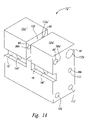
FIG. 14 is an isometric view of the solid body shown in FIG. 13.
FIG. 15 is an isometric view of the solid body shown in FIG. 13 showing the internal gas passageways.
DETAILED DESCRIPTION OF THE INVENTION
As will be discussed in greater detail herein, a dual gauge system determines pressures of two separately contained gases by use of two separate pointer—Bourbon tube sections within the dual gauge. The Bourdon tube of a first one of the sections is gaseously coupled to a first one of the contained gases to determine pressure of the first one of the contained gases and a Bourdon tube of a second one of the sections is gaseously coupled to a second one of the contained gases to determine pressure of the second one of the contained gases. Accuracy of pressure determination is enhanced by allowing for separate calibration of each of the two gauge sections as explained further below.
A conventional single pointer gauge 10 is shown in FIG. 1 as having a support 12 with threaded gas inlet 14 receiving pressurized gas 16 and outputting the pressurized gas through an opening (not shown) of a channel 18 to a Bourdon tube 20 fixedly coupled to the channel. A first end 22 of the Bourdon tube 20 has an opening 24 allowing access to the interior of the hollow Bourdon tube to receive the pressurized gas.
The first end 22 of the Bourdon tube 20 is shaped to mate with the channel 18 of the support 12 so that the Bourdon tube can be securely coupled to the support. A sealed second end 26 of the Bourdon tube 20 is fixedly coupled to a link attachment 28, which is rotatably coupled to a linkage 30 with a pin 32 through a passageway 28 a of the attachment and a passageway 34 a of a first end 34 of the linkage. The linkage 30 is rotatably coupled to a lever arm 36 with a pin 38 through a passageway 40 a of a second end 40 of the linkage and a passageway 42 a of a first end 42 of the lever arm. The lever arm 36 is fixedly coupled to a shaft 46 through a passageway 48 a in a mid-portion 48 of the lever arm.
The shaft 46 is rotatably coupled to a first bracket 50 through a passageway 51 a at a first position 51 of the first bracket. The shaft 46 is rotatably coupled to a second bracket 52 through a passageway 53 a at a first position 53 of the second bracket. The lever arm 36 has a rack gear 54 positioned at a second end 56 of the lever arm that engages with a pinion gear 58 on a shaft 60. The shaft 60 is rotatably coupled to the first bracket 50 through a passageway 62 a at a second position 62 of the first bracket and is rotatably coupled to the second bracket 52 through a passageway 63 a at a second position 63. When the conventional single pointer gauge 10 is assembled, the shaft 60 extends through the first bracket 50 and further extends through a dial face 64 at a first position 66.
The shaft 60 is fixedly coupled to a pointer 68, which indicates pressure by pointing to one of a series of pressure value demarcations 70 displayed on the dial face 64. The shaft 60 is secured from vibrational movement by a biasing spring 74. The first bracket 50 and the second bracket 52 are fixedly coupled together with pins 76 coupled through passageways 80 a at second positions 80 of the first bracket and coupled through passageways 82 a at second positions 82 of the second bracket. Distance between the first bracket 50 and the second bracket 52 is maintained by collars 83 being positioned on the pins 76 between the first bracket and the second bracket. The first bracket 50 is rotatably coupled to a pin 84 wherein the pin extends through a passageway 86 a at a third position 86 on the first bracket and fixedly couples to the support 12 through a passageway 88 a in a first position 88 on the support.
A shaft 90 (better shown in FIG. 2 and FIG. 3) with a cam 92 and a screw head 94 extends through an elongated passageway 96 a at a fourth position 96 in the first bracket 50 to be rotatably coupled to the support 12 through a passageway 98 a at a second position 98 in the support. The head 94 of the shaft 90 extends through a passageway 94 a in the dial face 64 to be accessible for calibration of the gauge 10. The cam 92 of the shaft 90 engages the first bracket 50 at the elongated passageway 96 a so that as the shaft is rotated, the first bracket will rotate about the pin 84. Angular positioning of the first bracket 50 about the pin 84 will determine location of the pointer 68 on the dial face 64 for a given shape of the Bourdon tube 20 thereby allowing calibration of the gauge 10 through repositioning of the various elements that implement motion conversion of shape change of the Bourdon tube 20 into rotation of the shaft 60. This calibration adjustment is provided since rotation of the shaft 90 and subsequent change in angular position of the first bracket 50 about the pin 84 will change the position of the passageway 48 aof the lever arm 36 relative to the position of the passageway 28 a in the link attachment 28. As the position of the passageway 48 a changes relative to the passageway 28 a, the rotational position of the lever arm 36 also changes with respect to a given shape of the Bourdon tube 20. Consequently, the pinion gear 58 will rotate with the change in rotational position of the lever arm 36 causing the pointer 68 to change position as the Bourdon tube 20 retains the given shape. For mounting of the dial face 64, a spacer 99 is fixedly coupled to the support 12 at attachment points 102 by use of screws 104 placed through passageways 104′ in the dial face 64 and passageways 104″ in the spacer.
A dual calibration gauge 100 is shown in FIG. 4 as having a first pointer 68′ indicating on the dial face 64 pressure of a first gas 16′ entering a first gas inlet 14′ of a first support 12′. The dual calibration gauge 100 also includes a second pointer 68″ indicating on the dial face 64 pressure of a second gas 16″ entering a second gas inlet 14″ of a second support 12″. A first screw head 94′ is used to calibrate positioning of the first pointer 68′ and a second screw head 94″ is used to calibrate positioning of the second pointer 68″. In some implementations, the first screw head 94′, the first gas inlet 14′, and the first pointer 68′ have a first color such as by being painted the first color or by being colored by some other way whereas the second screw head 94″, the second gas inlet 14″, and the second pointer 68″ have a second color different than the first color for identification purposes.
A first section 110 of components of the dual gauge 100 to measure pressure of the first gas 16′ is shown in FIGS. 5 and 6. The first section 110 has the first support 12′, which includes an access passageway 112 a in a third position 112 that receives and allows access to the second screw head 94″ from the dial face 64. The first section 110 also includes a first shaft 60′ similar to the shaft 60 except that the first shaft is hollow so has a cylindrical passageway 114.
A second section 120 of components of the dual gauge 100 to measure pressure of the second gas 16″ is shown in FIGS. 7 and 8. The second section 110 has the second support 12″, which includes a passageway 112 a′ in the third position 112 that receives the shaft 90 of the second screw head 94″. The second support 12″ does not include the passageway 98 a in the second position 98. The second section 120 includes a shaft 60″ having a diameter sufficiently small to pass through the passageway 114 of the first shaft 60′ so that the first shaft 60′ is fixedly attached to the first pointer 68′ and the second shaft 60″ is fixedly attached to the second pointer 68″.
A first bracket 50″ has a passageway 62 a′ in the second position 62 of a smaller diameter than the passageway 62 a in the second position 62 of the first bracket 50 of the first section to receive the smaller diameter shaft 60″ of the second section. The first bracket 50″ has the elongated passageway 96 a in a lower fourth position 96′ than the fourth position 96 of the elongated passageway of the first bracket 50 of the first section 110 since the shaft 90 and the screw head 94″ of the second section 120 is positioned below the shaft 90 and the screw head 94′ of the first section 110.
After the first section 110 and the second section 120 are individually assembled, they are joined together, as shown in FIG. 9, using, for instance, a bracket 126. As assembled, the shaft 60″ of the second section 120 extends through the shaft 60′ of the first section 110. Further, the screw head 94″ of the second section 120 extends through the support 12′ of the first section.
An alternative implementation of the dual gauge 100, shown in FIG. 10, uses first tubing 130′ affixed to a side 132′ of the first support 12′ and second tubing 130″ affixed to a side 132″ of the second support 12′ to route the first gas inlet 14′ and the second gas inlet 14″, respectively. As shown in FIG. 11, the first gas inlet 14′ and the second gas inlet 14″ can be affixed to a wall 134 opposite in direction to the dial face 64. Another implementation in which the second tubing 130″ is shortened by being affixed to an opposite side 136″ of the second support 12″ is shown in FIG. 12. Other implementations using various other routing paths for tubing are further contemplated.
A modified dual gauge implementation 137 is partially shown in FIGS. 13–15 in which a modified first support 12 m′ and a modified second support 12 m″ of a common support 12′″ have other components in common with the implementations of the dual gauge 100 previously described. Instead of using two of the pins 84 found with the implementations of the dual gauge 100 previously described, the implementation 137 has a double pin 138 with a larger diameter pin 84′ (used for the modified first support 12 m′) formed as a single unit with the pin 84 (used for the modified second support 12 m″). To receive the larger diameter pin 84′, a larger diameter passageway 88 a′ is located at the first position 88′ of the modified first support 12 m′.
In the implementation 137, the screw head 94″ is located above the screw head 94′, which is opposite that for the implementations of the dual gauge 100 previously described. As a consequence, a first bracket 50′″ of the modified first support 12 m′ and a first bracket 50″″ of the modified second support 12 m″ are similarly shaped like the first bracket 50″ of the second section and the first bracket 50 of the first section, respectively, of the implementations of the dual gauge 100 previously discussed. For instance, the first bracket 50′″ has the elongated passageway 96 a in the lower fourth position 96′ also found on the first bracket 50″.
The first bracket 50′″ has a notch N cut away to allow the shaft 90 with the screw head 94″ to pass through the access passageway 112 a in the modified first support 12 m′ now located at the second position 98 instead of the third position 112 as found with the first support 12′ of the first section 110 of the implementations of the dual gauge 100 previously described. The shaft 90 of the screw head 94′ is received by the passageway 98 a at the third position 112 rather than the second position 98 as found with the first support 12′ of the previously described implementations of the dual gauge 100.
The first bracket 50″″ of the modified second support 12 m″ is positioned in a slot 139 formed in the common support 12′″. Also in concert with the swapping of positional order of the screw head 94′ and the screw head 94″, the first bracket 50″″ has the elongated passageway 96 a in the fourth position 96.
The common support 12′″ includes a first channel 18′ and a second channel 18″ for the Bourdon tubes 20 for the first pointer 68′ and the second pointer 68″, respectively, as shown in FIGS. 14 and 15. A first internal passageway 140′ within the common support 12′″ connects the Bourdon tube for the first pointer 68′ to the first gas inlet 14′ of the first gas 16′. A second internal passageway 140″ within the common support 12′″ connects the Bourdon tube for the second pointer 68″ to the second gas inlet 14″ for the second gas 16″.
From the foregoing it will be appreciated that, although specific embodiments of the invention have been described herein for purposes of illustration, various modifications may be made without deviating from the spirit and scope of the invention. Accordingly, the invention is not limited except as by the appended claims.

Claims (9)

1. A gauge comprising:
a dial face having a first side and a second side, the second side having demarcations, the dial face having a passageway;
a first gauge portion including:
a pointer;
a first member having a longitudinal axis, the first member including a first portion and a second portion, the first member extending along the longitudinal axis from the first portion behind the first side of the dial face through the passageway of the dial face to the second portion in front of the second side of the dial face, the second portion coupled to the pointer, the first portion including a pinion gear;
a Bourdon tube configured to change shape based on a difference between gas pressure inside and outside of the Bourdon tube;
a bracket having a location point;
a lever pivotally coupled to the bracket at the location point, the lever linked to the Bourdon tube for the lever to pivot about the location point of the bracket when the position of the location point remains stationary and the Bourdon tube changes shape, the lever linked to the Bourdon tube for the lever to pivot about the location point when the position of the location point changes and the Bourdon tube retains a shape, the lever including a rack gear coupled to the pinion gear of the first member to rotate the first member about the longitudinal axis as the lever pivots about the location point; and
a second member coupled to the bracket to move the location point of the bracket as the second member moves; and
a second gauge portion including:
a pointer;
a first member having a longitudinal axis, the first member including a first portion and a second portion, the first member extending along the longitudinal axis from the first portion behind the first side of the dial face through the passageway of the dial face to the second portion in front of the second side of the dial face, the second portion coupled to the pointer, the first portion including a pinion gear;
a Bourdon tube configured to change shape based on difference between gas pressure inside and outside of the Bourdon tube;
a bracket having a location point;
a lever pivotally coupled to the bracket at the location point, the lever linked to the Bourdon tube for the lever to pivot about the location point of the bracket when the position of the location point remains stationary and the Bourdon tube changes shape, the lever linked to the Bourdon tube for the lever to pivot about the location point when the position of the location point changes and the Bourdon tube retains a shape, the lever including a rack gear coupled to the pinion gear of the first member to rotate the first member about the longitudinal axis as the lever pivots about the location point; and
a second member coupled to the bracket to move the location point of the bracket as the second member moves.
2. The gauge of claim 1 wherein the first member of the first gauge portion is hollow and the first member of the second gauge portion extends through the first member of the first gauge portion.
3. A gauge comprising:
a dial face having a first side and a second side, the second side having demarcations, the dial face having a passageway;
a first gauge portion including:
a pointer;
a first member having a longitudinal axis, the first member including a first portion and a second portion, the first member extending along the longitudinal axis from the first portion behind the first side of the dial face through the passageway of the dial face to the second portion in front of the second side of the dial face, the second portion coupled to the pointer;
a Bourdon tube configured to change shape based on a difference between gas pressure inside and outside of the Bourdon tube;
a motion converter coupled to the Bourdon tube and the first portion of the first member to rotate the first member about the longitudinal axis of the first member when the Bourdon tube changes shape; and
a second member coupled to the motion converter to rotate the first member about the longitudinal axis of the first member when the second member moves and the Bourdon tube retains a shape; and
a second gauge portion including:
a pointer;
a first member having a longitudinal axis, the first member including a first portion and a second portion, the first member extending along the longitudinal axis from the first portion behind the first side of the dial face through the passageway of the dial face to the second portion in front of the second side of the dial face, the second portion coupled to the pointer;
a Bourdon tube configured to change shape based on a difference between gas pressure inside and outside of the Bourdon tube;
a motion converter coupled to the Bourdon tube and the first portion of the first member to rotate the first member about the longitudinal axis of the first member when the Bourdon tube changes shape; and
a second member coupled to the motion converter to rotate the first member about the longitudinal axis of the first member when the second member moves and the Bourdon tube retains a shape.
4. A gauge comprising:
a dial face having a first side and a second side, the second side having demarcations, the dial face having at least one passageway;
a first pointer;
a first pointer shaft having first and second open ends to access a passageway, the first pointer shaft extending through the at least one passageway of the dial face and coupled to the first pointer on the second side of the dial face;
a first support having a gas passageway and a gas inlet allowing access to the gas passageway, the first support located behind the first side of the dial face, the first support having a first side facing the dial face and a second side opposite the first side, the first side having an opening and the second side having an opening, the first support having a shaft passageway extending between the opening of the first side and the opening of the second side;
a first Bourdon tube coupled to the first support, the first Bourdon tube having an internal cavity coupled to the gas passageway of the first support;
a first motion converter coupled to the first Bourdon tube and coupled to the first pointer shaft to rotate the first pointer shaft about the longitudinal axis of the first pointer shaft when the first Bourdon tube changes shape, a portion of the first motion converter pivotally coupled to the first support to rotate the first pointer shaft about the longitudinal axis of the first pointer shaft when the first Bourdon tube retains a shape and the portion pivots;
a first calibration shaft having a longitudinal axis, the first calibration shaft extending through the at least one passageway of the dial face from behind the first side of the dial face to the second side of the dial face, the first calibration shaft coupled to the portion of the first motion converter to pivot the pivotally coupled portion of the first motion converter as the first calibration shaft rotates about the longitudinal axis of the first calibration shaft;
a second pointer;
a second pointer shaft extending through the passageway of the first pointer shaft, the second pointer shaft extending through the at least one passageway of the dial face and coupled to the second pointer on the second side of the dial face;
a second support having a gas passageway and a gas inlet allowing access to the gas passageway, the second support located behind the first side of the dial face on the second side of the first support;
a second Bourdon tube coupled to the second support, the second Bourdon tube having an internal cavity coupled to the gas passageway of the second support;
a second motion converter coupled to the second Bourdon tube and coupled to the second pointer shaft to rotate the second pointer shaft about the longitudinal axis of the second pointer shaft when the second Bourdon tube changes shape, a portion of the second motion converter pivotally coupled to the second support to rotate the second pointer shaft about the longitudinal axis of the second pointer shaft when the second Bourdon tube retains a shape and the portion pivots; and
a second calibration shaft having a longitudinal axis, the second calibration shaft extending through the passageway of the first support and extending through at the least one passageway of the dial face from behind the first side of the dial face to the second side of the dial face, the second calibration shaft coupled to the portion of the second motion converter to pivot the pivotally coupled portion of the second motion converter as the second calibration shaft rotates about the longitudinal axis of the second calibration shaft.
5. The gauge of claim 4 further including a first tubing coupled to the gas inlet of the first support and a second tubing coupled to the gas inlet of the second support.
6. The gauge of claim 5 wherein the first calibration shaft further includes a cam for coupling with the pivotally coupled portion of the first motion converter and the second calibration shaft further includes a cam for coupling with the pivotally coupled portion of the second motion converter.
7. A gauge comprising:
a dial face having a first side and a second side, the second side having demarcations, the dial face having at least one passageway;
a first pointer;
a first pointer shaft extending through the at least one passageway of the dial face and coupled to the first pointer on the second side of the dial face;
a common support having a first gas inlet, a first opening, a second gas inlet, a second opening, a first gas passageway extending between the first gas inlet and the first opening, and a second gas passageway extending between the second gas inlet and the second opening, the common support located behind the first side of the dial face;
a first Bourdon tube coupled to the common support, the first Bourdon tube having an internal cavity coupled to the first gas passageway through the first opening of the common support;
a first motion converter coupled to the first Bourdon tube and coupled to the first pointer shaft to rotate the first pointer shaft about the longitudinal axis of the first pointer shaft when the first Bourdon tube changes shape, a portion of the first motion converter moveably coupled to the common support to rotate the first pointer shaft about the longitudinal axis of the first pointer shaft when the first Bourdon tube retains a shape and the portion moves;
a first calibration shaft having a longitudinal axis, the first calibration shaft extending through the at least one passageway of the dial face from behind the first side of the dial face of the second side of the dial face, the first calibration shaft coupled to the portion of the first motion converter to move the moveably coupled portion of the first motion converter as the first calibration shaft rotates about the longitudinal axis of the first calibration shaft;
a second pointer;
a second pointer shaft extending through the at least one passageway of the dial face and coupled to the second pointer on the second side of the dial face;
a second Bourdon tube coupled to the common support, the second Bourdon tube having an internal cavity coupled to the second gas passageway through the second opening of the common support;
a second motion converter coupled to the second Bourdon tube and coupled to the second pointer shaft to rotate the second pointer shaft about the longitudinal axis of the second pointer shaft when the second Bourdon tube changes shape, a portion of the second motion converter moveably coupled to the common support to rotate the second pointer shaft about the longitudinal axis of the second pointer shaft when the second Bourdon tube retains a shape and the portion moves; and
a second calibration shaft having a longitudinal axis, the second calibration shaft extending through the at least one passageway of the dial face from behind the first side of the dial face to the second side of the dial face, the second calibration shaft coupled to the portion of the second motion converter to move the moveably coupled portion of the second motion converter as the second calibration shaft rotates about the longitudinal axis of the second calibration shaft.
8. The gauge of claim 7 wherein the common support has a first side and a second side opposite the first side, the first side being positioned to face the first side of the dial face, and wherein the first gas inlet and the second gas inlet are on the second side of the common support.
9. The gauge of claim 8 wherein the common support has a shaft passageway extending from the first side of the common support to a mid-portion of the common support and wherein the second calibration shaft extends through the shaft passageway from the first face of the common support to where the second calibration shaft is coupled to the second motion converter.
US11/107,388 2004-04-15 2005-04-15 Dual gauge with dual calibration system and method Active US7124642B2 (en)

Priority Applications (1)

Application Number Priority Date Filing Date Title
US11/107,388 US7124642B2 (en) 2004-04-15 2005-04-15 Dual gauge with dual calibration system and method

Applications Claiming Priority (2)

Application Number Priority Date Filing Date Title
US56293604P 2004-04-15 2004-04-15
US11/107,388 US7124642B2 (en) 2004-04-15 2005-04-15 Dual gauge with dual calibration system and method

Publications (2)

Publication Number Publication Date
US20060096382A1 US20060096382A1 (en) 2006-05-11
US7124642B2 true US7124642B2 (en) 2006-10-24

Family

ID=36314960

Family Applications (1)

Application Number Title Priority Date Filing Date
US11/107,388 Active US7124642B2 (en) 2004-04-15 2005-04-15 Dual gauge with dual calibration system and method

Country Status (1)

Country Link
US (1) US7124642B2 (en)

Cited By (2)

* Cited by examiner, † Cited by third party
Publication number Priority date Publication date Assignee Title
US20070295097A1 (en) * 2006-02-17 2007-12-27 Yugenngaisya Fuji Burudon Seisakusho Bourdon tube pressure gauge
WO2015039494A1 (en) * 2013-09-18 2015-03-26 上海乐研电气科技有限公司 Highly shock-resistant sulphur hexafluoride gas density relay

Families Citing this family (4)

* Cited by examiner, † Cited by third party
Publication number Priority date Publication date Assignee Title
CN102353495B (en) * 2011-06-23 2013-11-06 天津市泰菲特仪器仪表技术有限公司 Pressure measurement device applied to environments with non-standard atmospheric pressure
DE102015008098B4 (en) 2015-06-25 2023-03-30 Wika Alexander Wiegand Se & Co. Kg Measuring device with spread measured value output
US11300466B1 (en) * 2020-11-24 2022-04-12 Porauto Industrial Co., Ltd. Pressure gauge with dual bourdon tubes
TWI792525B (en) * 2021-08-30 2023-02-11 雙餘實業股份有限公司 Pressure gauge with divisional scale

Citations (5)

* Cited by examiner, † Cited by third party
Publication number Priority date Publication date Assignee Title
US3956920A (en) * 1975-04-14 1976-05-18 Herman Richard Kollmeyer Dual function pressure transducer
US4058016A (en) * 1976-04-01 1977-11-15 Rite Autotronics Corporation Combination vacuum/pressure gauge and dual purpose casing construction
US4916944A (en) * 1989-02-16 1990-04-17 Ho Chuan King Dual purpose tire gauge
US5363703A (en) * 1993-07-06 1994-11-15 Panex Corporation Dual transducer
US5652391A (en) * 1995-05-12 1997-07-29 Furon Company Double-diaphragm gauge protector

Patent Citations (5)

* Cited by examiner, † Cited by third party
Publication number Priority date Publication date Assignee Title
US3956920A (en) * 1975-04-14 1976-05-18 Herman Richard Kollmeyer Dual function pressure transducer
US4058016A (en) * 1976-04-01 1977-11-15 Rite Autotronics Corporation Combination vacuum/pressure gauge and dual purpose casing construction
US4916944A (en) * 1989-02-16 1990-04-17 Ho Chuan King Dual purpose tire gauge
US5363703A (en) * 1993-07-06 1994-11-15 Panex Corporation Dual transducer
US5652391A (en) * 1995-05-12 1997-07-29 Furon Company Double-diaphragm gauge protector

Cited By (3)

* Cited by examiner, † Cited by third party
Publication number Priority date Publication date Assignee Title
US20070295097A1 (en) * 2006-02-17 2007-12-27 Yugenngaisya Fuji Burudon Seisakusho Bourdon tube pressure gauge
US7555959B2 (en) * 2006-02-17 2009-07-07 Yugenngaisya Fuji Burudon Seisakusho Bourdon tube pressure gauge
WO2015039494A1 (en) * 2013-09-18 2015-03-26 上海乐研电气科技有限公司 Highly shock-resistant sulphur hexafluoride gas density relay

Also Published As

Publication number Publication date
US20060096382A1 (en) 2006-05-11

Similar Documents

Publication Publication Date Title
US7124642B2 (en) Dual gauge with dual calibration system and method
JP3233645B2 (en) Measurement device mechanism
EP2252868B1 (en) Span adjustment for suspended movement measuring devices
JP4625220B2 (en) Linearity adjustment mechanism for suspension-type pressure gauge
US6085595A (en) High range pressure sensor for pressure gauge
JPS6136609B2 (en)
WO2001076470A2 (en) Physical quantity measuring device
CN105135994A (en) Measurer for angle calibration on adjustable stator blade of compressor
JPS6270723A (en) Pressure gage
US20080189967A1 (en) Standardizable level tool
US7165461B2 (en) Pressure gauge having dual function movement plate
US2925734A (en) Gauge with flexible stem
US8955398B2 (en) Individual tensiometer for measuring tension in a string
US7350414B1 (en) Mechanical barometer
US2324666A (en) Adjustable linkage for pressure measuring instruments
US8893553B2 (en) Zero/span adjustable linkage movement for measuring devices
CN219573357U (en) Tension meter calibrating device
US2141211A (en) Gauge
US2431098A (en) Mechanical movement
US7574815B1 (en) Wheeled distance measuring device
CN108627063B (en) Digital display caliper with adjustable measuring range
US3559489A (en) Bar stock zero adjustment with stop
US4825699A (en) Non-deflectable adjustable bourdon gauge
US3308655A (en) Vehicle fuel consumption indicating instrument
JP6154623B2 (en) Pressure gauge

Legal Events

Date Code Title Description
AS Assignment

Owner name: RIGHT WEIGH, INC., OREGON

Free format text: ASSIGNMENT OF ASSIGNORS INTEREST;ASSIGNORS:CAMPBELL, SIDNEY R.;KOPE, TYLER R.M.;REEL/FRAME:016251/0183;SIGNING DATES FROM 20050525 TO 20050608

STCF Information on status: patent grant

Free format text: PATENTED CASE

FPAY Fee payment

Year of fee payment: 4

FPAY Fee payment

Year of fee payment: 8

FEPP Fee payment procedure

Free format text: MAINTENANCE FEE REMINDER MAILED (ORIGINAL EVENT CODE: REM.)

FEPP Fee payment procedure

Free format text: 11.5 YR SURCHARGE- LATE PMT W/IN 6 MO, SMALL ENTITY (ORIGINAL EVENT CODE: M2556); ENTITY STATUS OF PATENT OWNER: SMALL ENTITY

MAFP Maintenance fee payment

Free format text: PAYMENT OF MAINTENANCE FEE, 12TH YR, SMALL ENTITY (ORIGINAL EVENT CODE: M2553); ENTITY STATUS OF PATENT OWNER: SMALL ENTITY

Year of fee payment: 12