US7020892B2 - Time-shifted video signal processing - Google Patents
Time-shifted video signal processing Download PDFInfo
- Publication number
- US7020892B2 US7020892B2 US09/390,090 US39009099A US7020892B2 US 7020892 B2 US7020892 B2 US 7020892B2 US 39009099 A US39009099 A US 39009099A US 7020892 B2 US7020892 B2 US 7020892B2
- Authority
- US
- United States
- Prior art keywords
- time
- signal
- mode
- real
- shifted
- Prior art date
- Legal status (The legal status is an assumption and is not a legal conclusion. Google has not performed a legal analysis and makes no representation as to the accuracy of the status listed.)
- Expired - Lifetime, expires
Links
Images


Classifications
-
- H—ELECTRICITY
- H04—ELECTRIC COMMUNICATION TECHNIQUE
- H04N—PICTORIAL COMMUNICATION, e.g. TELEVISION
- H04N21/00—Selective content distribution, e.g. interactive television or video on demand [VOD]
- H04N21/40—Client devices specifically adapted for the reception of or interaction with content, e.g. set-top-box [STB]; Operations thereof
- H04N21/41—Structure of client; Structure of client peripherals
- H04N21/414—Specialised client platforms, e.g. receiver in car or embedded in a mobile appliance
- H04N21/4147—PVR [Personal Video Recorder]
-
- H—ELECTRICITY
- H04—ELECTRIC COMMUNICATION TECHNIQUE
- H04N—PICTORIAL COMMUNICATION, e.g. TELEVISION
- H04N21/00—Selective content distribution, e.g. interactive television or video on demand [VOD]
- H04N21/40—Client devices specifically adapted for the reception of or interaction with content, e.g. set-top-box [STB]; Operations thereof
- H04N21/43—Processing of content or additional data, e.g. demultiplexing additional data from a digital video stream; Elementary client operations, e.g. monitoring of home network or synchronising decoder's clock; Client middleware
- H04N21/433—Content storage operation, e.g. storage operation in response to a pause request, caching operations
- H04N21/4333—Processing operations in response to a pause request
-
- H—ELECTRICITY
- H04—ELECTRIC COMMUNICATION TECHNIQUE
- H04N—PICTORIAL COMMUNICATION, e.g. TELEVISION
- H04N21/00—Selective content distribution, e.g. interactive television or video on demand [VOD]
- H04N21/40—Client devices specifically adapted for the reception of or interaction with content, e.g. set-top-box [STB]; Operations thereof
- H04N21/43—Processing of content or additional data, e.g. demultiplexing additional data from a digital video stream; Elementary client operations, e.g. monitoring of home network or synchronising decoder's clock; Client middleware
- H04N21/44—Processing of video elementary streams, e.g. splicing a video clip retrieved from local storage with an incoming video stream, rendering scenes according to MPEG-4 scene graphs
- H04N21/4402—Processing of video elementary streams, e.g. splicing a video clip retrieved from local storage with an incoming video stream, rendering scenes according to MPEG-4 scene graphs involving reformatting operations of video signals for household redistribution, storage or real-time display
- H04N21/440281—Processing of video elementary streams, e.g. splicing a video clip retrieved from local storage with an incoming video stream, rendering scenes according to MPEG-4 scene graphs involving reformatting operations of video signals for household redistribution, storage or real-time display by altering the temporal resolution, e.g. by frame skipping
-
- H—ELECTRICITY
- H04—ELECTRIC COMMUNICATION TECHNIQUE
- H04N—PICTORIAL COMMUNICATION, e.g. TELEVISION
- H04N5/00—Details of television systems
- H04N5/76—Television signal recording
-
- H—ELECTRICITY
- H04—ELECTRIC COMMUNICATION TECHNIQUE
- H04N—PICTORIAL COMMUNICATION, e.g. TELEVISION
- H04N5/00—Details of television systems
- H04N5/76—Television signal recording
- H04N5/78—Television signal recording using magnetic recording
- H04N5/782—Television signal recording using magnetic recording on tape
- H04N5/783—Adaptations for reproducing at a rate different from the recording rate
-
- H—ELECTRICITY
- H04—ELECTRIC COMMUNICATION TECHNIQUE
- H04N—PICTORIAL COMMUNICATION, e.g. TELEVISION
- H04N9/00—Details of colour television systems
- H04N9/79—Processing of colour television signals in connection with recording
- H04N9/80—Transformation of the television signal for recording, e.g. modulation, frequency changing; Inverse transformation for playback
- H04N9/804—Transformation of the television signal for recording, e.g. modulation, frequency changing; Inverse transformation for playback involving pulse code modulation of the colour picture signal components
- H04N9/8042—Transformation of the television signal for recording, e.g. modulation, frequency changing; Inverse transformation for playback involving pulse code modulation of the colour picture signal components involving data reduction
Definitions
- This invention relates to time-shifted video signal processing.
- a viewer of “real-time” video cannot normally perform the kinds of “trick” functions, such as pause, play, fast forward, or reverse, that are available for recorded video.
- the play back can be delayed (time-shifted) by as much as the storage size, and as little as the system delay, referred to as “near real time”.
- the trick functions then can be provided from the stored version.
- a time-shifted system 10 may use a digitized, uncompressed video signal 12 that is derived from an incoming broadcast analog TV signal or other source.
- Signal 12 is encoded (compressed into, e.g., MPEG format) in an encoder 14 .
- a host controller 20 then writes the compressed frames in a storage buffer 24 (e.g., a hard disk). For viewing, the host controller 20 reads (reading and writing occur simultaneously) the compressed video from the storage buffer and delivers it to a video decoder 18 .
- the video decoder produces a time-shifted decoded uncompressed output 28 that is displayed to the viewer.
- the delay between the input signal and the time-shifted decoded output will vary depending on system hardware and software implementation as well as compression technique used.
- the input is a transport signal 13 that carries multiplexed compressed (e.g., MPEG) digital video signals.
- a transport de-multiplexer 15 provides demultiplexed compressed signals that the host controller stores and delivers as in FIG. 1 .
- the invention features a time-shifted video method having a real-time mode during which real-time video frames are delivered for display.
- a time-shifted mode time-shifted video frames are delivered for display.
- the time-shifted video frames are delayed relative to the real-time video frames.
- a real-time frame is paused during a transition from the real-time mode to the time-shifted mode.
- the transition may be between the paused real-time frame and a time-shifted version of the paused real-time frame.
- Trick functions may be provided during the time-shifted mode.
- the transition mode may be triggered by a command of a viewer or an event generated by software.
- the real-time video frames may be derived from input uncompressed video.
- the real-time video frames may be provided from an input frame buffer, from input compressed video or from a decoder that decompresses the input compressed video.
- the real-time mode, the time-shifted mode, and the transition may be provided by a single codec chip.
- the compressed video may comprise MPEG video.
- the information may be stored identifying the paused frame. Before the time-shifted mode occurs, the predetermined frame or the next frame after the predetermined frame may be queued up.
- the invention features apparatus that includes a port to receive an input video signal, a time-shifted processing path that stores compressed video frames based on the input video signal and delivers time-shifted stored video frames to an output, a real-time processing path that delivers real-time video to the output based on the input video signal, and control circuitry that controls transitions between the real-time video frames and the time-shifted video frames at the output.
- Implementations of the invention may include one or more of the following features.
- the processing paths may include two decoders in a single codec.
- the processing paths may include buffers provided by a common memory.
- the apparatus may comprise a set-top box or an analog television receiver.
- Incoming video signals can be viewed without going through the system pipeline, thus permitting quick channel changes.
- the viewer can switch seamlessly between the incoming and time-delayed video signals. Transitions to and from trick functions can be provided seamlessly.
- Set-top box and analog receiver implementations are possible. System bandwidth requirements are reduced and hard disc life span increased by not having to read back from the storage media in normal “real-time” operation.
- FIG. 1 is a block diagram of a time-shifted system that uses an uncompressed digital video input.
- FIG. 2 is a block diagram of a time-shifted system that uses a compressed digital video input.
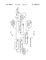
- FIG. 3 is a block diagram of an improved time-shifted system that uses an uncompressed digital video input.
- FIG. 4 is a block diagram of an improved time-shifted system that uses a compressed digital video input.
- FIG. 5 is a flow diagram.
- FIG. 6 is a block diagram of a buffer configuration.
- FIG. 7 is a block diagram of a single-chip configuration.
- incoming uncompressed video is stored in a frame buffer 29 and used to provide real-time uncompressed video 31 for display through a switch 23 .
- the same incoming uncompressed video 12 is used to generate a time-shifted uncompressed output 28 (in a manner similar to FIG. 1 ) that may also be delivered through switch 23 .
- a second video decoder 34 is added to supplement the existing video decoder 18 of FIG. 2 .
- Decoder 18 delivers a time-shifted decoded output 28 like the one generated by decoder 18 in FIG. 1 with a timing T 3 that is delayed relative to T 1 by a delay d.
- Delay d can be as large as the number of frames in the storage buffer (e.g., if the viewer has chosen to play back the oldest available frames) and as small as the minimum combined delay of the storage system and the decoder 18 (e.g., if the viewer is viewing the most recently stored frames).
- FIGS. 3 and 4 have essentially two display modes, real-time and time-shifted.
- the displayed output will be switched between “time-shifted” and “near real-time” outputs as needed, using “near real-time” when viewing the live broadcast and during channel changes and “time-shifted” when doing trick modes or when viewing recorded material.
- the system operates much as a conventional receiver, delivering the incoming uncompressed digital video signal directly from buffer 29 to the output for display through switch 23 .
- a compressed version of the incoming video is continually generated by encoder 14 and stored in buffer 24 but the video stored there is not used for the output during real-time display.
- the display will remain in real-time mode until a trick play is requested. If the viewer commands the system to pause, the system continues to display the frame that was in the frame buffer 29 at the time the pause was invoked. The paused frame is marked with an indicator (stamp), and is encoded normally. While the real-time video is paused, encoding and storage continue to occur. The decoder decodes the stream until the marked frame is reached and then pauses on the next frame. The display is still showing the paused frame buffer 29 at this stage.
- the time-shifted decoder 18 When the time-shifted decoder 18 encounters the paused frame (identified by the stamp), it effectively queues up the next frame by not advancing to process any subsequent frame in the buffer. As soon as the next-after-paused frame is queued, the host controller can switch the display output to the time-shift decoder when a single step or slow motion command is sent.
- the display transition from the frame buffer 29 to time-shifted material will be seamless to the viewer. Any other trick play command after pause will also cause the display output to switch, but only once the new frame or stream is queued. Doing a seamless switch in this case is not required.
- the host controller identifies the initial frame that is to be displayed to effect the trick feature, and the time-shift decoder queues up that frame. The display then switches the output video to the time-shift decoder.
- the time-shifted decoder resumes normal Decoding and the system enters the time-shift mode.
- the system will remain in time-shift display mode until a channel change command, or if the viewer selects to display the live broadcast and view the program in real time.
- the encode and storage process continues uninterrupted during all mode changes.
- two frame buffers 80 , 88 are used to buffer and process incoming uncompressed video and outgoing digital video frames.
- the encoder frame buffer 80 includes an area 83 that stores successive incoming uncompressed digital video frames F 1 . . . Fn and an area 84 that stores compressed (e.g., MPEG) frames that are generated by an (MPEG) encoder 82 based on the stored video frames in area 83 .
- compressed e.g., MPEG
- the decoder frame buffer 88 similarly has an area 86 that holds compressed frames and an area 92 that holds uncompressed video frames that are generated by time-shifted video decoder 18 from the compressed frames.
- the time-shifted decoded output 28 is displayed from the video frame area 92 .
- the real-time output 31 is displayed from area 83 of buffer 80 .
- the following paragraphs describe an internal implementation of a single CODEC solution for real-Time viewing and seamless switching to time-shifted material.
- the CODEC in this implementation is capable of sharing its memory between the encode and decode operations.
- the incoming digital video frames 78 are buffered into the encoder frame buffer area of the memory 80 before they are encoded.
- the number of frames buffered will depend on the compression method used. For MPEG2 IBBP, for example, at least enough frames must be stored to encode the next P frame.
- Each frame is encoded by encoder 82 in the order prescribed by the compression algorithm used, then stored as a compressed frame 84 in the frame buffer ready for transfer to the host.
- decoding In decoding, the process is reversed. Compressed video frames are first transferred into a decoder compressed frame buffer area 88 of the memory. The frames are decoded by decoder 18 , and the uncompressed frames are written to the decoder's video data buffer area of the memory 92 for display.
- the display output of switch 23 is set to the real-time output 31 , which is continually displaying the memory buffer containing the latest fully captured frame of video.
- the decoder 18 in this mode can be idle since nothing is displayed from its frame buffer 88 .
- This mode is indicated in block 201 of FIG. 5 .
- the display output 31 of the codec chip will be paused by reserving this memory area and keeping the display window set to the last captured frame in the encoder frame buffer 205 .
- the decoder output is not being viewed during this mode, it is possible to reclaim some of the decoder frame buffer 88 for use by the encoder. This is required since one frame area is locked in the pause mode but the encoder 82 still must continue encoding and needs all of its normally prescribed memory space.
- the same encoded frame must also be queued and ready to display at the output of the decoder.
- the pause function is invoked, the paused frame is encoded, marked, and stored normally 207 .
- the resulting video stream is then read back to the decoder, decoded, but not written to the display buffer 83 (now used by the encoder).
- the decoded result is written to the decoder frame buffer 88 , ready for display 209 .
- the output display is switched 211 as soon as the frame has been decoded and ready for display, and the locked memory area that was being used for the freeze frame is released back to the decoder.
- the display remains in time-shifted view 213 as long as it is not required to switch back to live (e.g., channel change 215 ).
- An alternative way to implement the switch to time-shift is to queue up the frame following the marked frame, and only switch once the next command is issued.
- a second decoder is required to provide the “real-time” view and the flow chart of FIG. 5 would be generally the same.
- the minimum delay in the system of FIG. 3 of the time-shifted signal would be D E +D S +D D
- the minimum delay in the system of FIG. 4 would be only D S +D D .
- the real-time output has a delay of one frame compared to the input (caused by the frame buffer) while in FIG. 4 , the delay is D D frames
- An efficient way to implement the system of FIG. 4 is to use a single codec chip of a kind that has the capability to decode (decompress) two incoming digital video signals simultaneously to perform the functions of both decoders 18 and 34 .
- such a single chip codec 108 when combined with a common memory 106 , may be used to implement a time-shifted system 100 that can handle both incoming compressed and incoming uncompressed video signals 104 , 102 .
- Memory 106 serves the functions of both of the buffers 80 , 88 of FIG. 6 .
- the resulting digital video output 111 is controlled by the host controller to be either real-time or time-shifted as needed.
- the paused frame may be marked by inserting the mark in the bitstream or the frame header, or by indexing in the system software.
- the paused frame may be marked by inserting the mark in the bitstream or the frame header, or by indexing in the system software.
- no marking is possible since the stream is not being manipulated, however, methods such as reading back the presentation time stamp from the decoder 34 can be used to queue up decoder 18 to the frame being paused.
- the invention can be implemented in a set-top box which is capable of handling either a compressed video input, an uncompressed video input, or both.
Abstract
Description
Claims (23)
Priority Applications (2)
| Application Number | Priority Date | Filing Date | Title |
|---|---|---|---|
| US09/390,090 US7020892B2 (en) | 1999-09-03 | 1999-09-03 | Time-shifted video signal processing |
| MXPA00008659A MXPA00008659A (en) | 1999-09-03 | 2000-09-04 | Time-shifted video signal processing. |
Applications Claiming Priority (1)
| Application Number | Priority Date | Filing Date | Title |
|---|---|---|---|
| US09/390,090 US7020892B2 (en) | 1999-09-03 | 1999-09-03 | Time-shifted video signal processing |
Publications (2)
| Publication Number | Publication Date |
|---|---|
| US20030170003A1 US20030170003A1 (en) | 2003-09-11 |
| US7020892B2 true US7020892B2 (en) | 2006-03-28 |
Family
ID=27789191
Family Applications (1)
| Application Number | Title | Priority Date | Filing Date |
|---|---|---|---|
| US09/390,090 Expired - Lifetime US7020892B2 (en) | 1999-09-03 | 1999-09-03 | Time-shifted video signal processing |
Country Status (2)
| Country | Link |
|---|---|
| US (1) | US7020892B2 (en) |
| MX (1) | MXPA00008659A (en) |
Cited By (98)
| Publication number | Priority date | Publication date | Assignee | Title |
|---|---|---|---|---|
| US20020172494A1 (en) * | 2001-05-15 | 2002-11-21 | Shouji Ueoka | Reproducing system |
| US20030097662A1 (en) * | 2000-11-14 | 2003-05-22 | Russ Samuel H. | Networked subscriber television distribution |
| US20030192047A1 (en) * | 2002-03-22 | 2003-10-09 | Gaul Michael A. | Exporting data from a digital home communication terminal to a client device |
| US20030226150A1 (en) * | 2000-01-27 | 2003-12-04 | Berberet Suzanne M. | System and method for providing broadcast programming, a virtual vcr, and a video scrapbook to programming subscribers |
| US20040068747A1 (en) * | 2002-10-02 | 2004-04-08 | Robertson Neil C. | Networked multimedia system |
| US20040068744A1 (en) * | 2000-11-14 | 2004-04-08 | Claussen Paul J. | Proximity detection using wireless connectivity in a communications system |
| US20040068752A1 (en) * | 2002-10-02 | 2004-04-08 | Parker Leslie T. | Systems and methods for providing television signals to multiple televisions located at a customer premises |
| US20040133911A1 (en) * | 2002-10-04 | 2004-07-08 | Russ Samuel H. | Subscriber network in a satellite system |
| US20050030910A1 (en) * | 2003-01-15 | 2005-02-10 | Robertson Neil C. | Full duplex wideband communications system for a local coaxial network |
| US20050125832A1 (en) * | 2003-12-03 | 2005-06-09 | Jost Arthur P. | Method and apparatus for cost effective central transcoding of video streams in a video on demand system |
| US20050155052A1 (en) * | 2002-10-04 | 2005-07-14 | Barbara Ostrowska | Parental control for a networked multiroom system |
| US20060010481A1 (en) * | 2002-10-04 | 2006-01-12 | Scientific-Atlanta, Inc. | Multiroom point of deployment module |
| US20060015922A1 (en) * | 2004-07-19 | 2006-01-19 | Lg Electronics Inc. | Method of processing files for data broadcasting |
| US20060095472A1 (en) * | 2004-06-07 | 2006-05-04 | Jason Krikorian | Fast-start streaming and buffering of streaming content for personal media player |
| US20060117354A1 (en) * | 2004-11-29 | 2006-06-01 | Mark Schutte | Consolidating video-on-demand (VOD) services with multi-room personal video recording (MR-PVR) services |
| US20060174262A1 (en) * | 2003-03-19 | 2006-08-03 | Koninklijke Philips Electronics N. V. | Method for transmitting a user-specific program |
| US20060253417A1 (en) * | 2005-05-06 | 2006-11-09 | Starz Entertainment Group Llc | Local context navigation system |
| US20060253887A1 (en) * | 2005-05-06 | 2006-11-09 | Starz Entertainment Group Llc | Methods for entertainment-programming distribution |
| US20070028290A1 (en) * | 2005-07-28 | 2007-02-01 | Ess Technology, Inc. | Method and device for timeshifting using external memory card |
| US20070089147A1 (en) * | 2002-05-03 | 2007-04-19 | Urdang Erik G | Technique for synchronizing deliveries of information and entertainment in a communications network |
| US7228559B1 (en) * | 1999-10-13 | 2007-06-05 | Starz Encore Group Llc | Programming distribution and notification system |
| US20080024679A1 (en) * | 2006-07-27 | 2008-01-31 | Samsung Electronics Co., Ltd | Method for changing channel according to status of image signal and image display apparatus adopting the method |
| US20080072275A1 (en) * | 2006-09-15 | 2008-03-20 | Samsung Electronics Co., Ltd | Video apparatus having exterior recording function and interior time shift function and broadcast processing method thereof |
| US20090282444A1 (en) * | 2001-12-04 | 2009-11-12 | Vixs Systems, Inc. | System and method for managing the presentation of video |
| US20100091985A1 (en) * | 2003-12-22 | 2010-04-15 | Aol Llc | System and method for using a streaming protocol |
| US7702952B2 (en) | 2005-06-30 | 2010-04-20 | Sling Media, Inc. | Firmware update for consumer electronic device |
| US7725912B2 (en) | 1999-05-26 | 2010-05-25 | Sling Media, Inc. | Method for implementing a remote display system with transcoding |
| US20100129051A1 (en) * | 2008-11-24 | 2010-05-27 | Mediatek Inc. | Multimedia recording apparatus and method |
| US7769756B2 (en) | 2004-06-07 | 2010-08-03 | Sling Media, Inc. | Selection and presentation of context-relevant supplemental content and advertising |
| US7870584B2 (en) | 2002-08-02 | 2011-01-11 | Russ Samuel H | Interactive program guide with selectable updating |
| US7876998B2 (en) | 2005-10-05 | 2011-01-25 | Wall William E | DVD playback over multi-room by copying to HDD |
| US20110035669A1 (en) * | 2009-08-10 | 2011-02-10 | Sling Media Pvt Ltd | Methods and apparatus for seeking within a media stream using scene detection |
| US20110069178A1 (en) * | 2009-09-23 | 2011-03-24 | At&T Intellectual Property I, L.P. | Multimedia interactive simulator |
| US7917932B2 (en) | 2005-06-07 | 2011-03-29 | Sling Media, Inc. | Personal video recorder functionality for placeshifting systems |
| US7950040B2 (en) | 1999-10-13 | 2011-05-24 | Starz Entertainment, Llc | Programming distribution system |
| US20110150432A1 (en) * | 2009-12-23 | 2011-06-23 | Sling Media Inc. | Systems and methods for remotely controlling a media server via a network |
| US7975062B2 (en) | 2004-06-07 | 2011-07-05 | Sling Media, Inc. | Capturing and sharing media content |
| US8060609B2 (en) | 2008-01-04 | 2011-11-15 | Sling Media Inc. | Systems and methods for determining attributes of media items accessed via a personal media broadcaster |
| US8060904B1 (en) | 2008-02-25 | 2011-11-15 | Qurio Holdings, Inc. | Dynamic load based ad insertion |
| US8099755B2 (en) | 2004-06-07 | 2012-01-17 | Sling Media Pvt. Ltd. | Systems and methods for controlling the encoding of a media stream |
| US8136133B2 (en) | 2007-11-13 | 2012-03-13 | Walker Digital, Llc | Methods and systems for broadcasting modified live media |
| US8171148B2 (en) | 2009-04-17 | 2012-05-01 | Sling Media, Inc. | Systems and methods for establishing connections between devices communicating over a network |
| US8266657B2 (en) | 2001-03-15 | 2012-09-11 | Sling Media Inc. | Method for effectively implementing a multi-room television system |
| US8312487B1 (en) | 2008-12-31 | 2012-11-13 | Qurio Holdings, Inc. | Method and system for arranging an advertising schedule |
| US8314893B2 (en) | 2009-08-28 | 2012-11-20 | Sling Media Pvt. Ltd. | Remote control and method for automatically adjusting the volume output of an audio device |
| US8346605B2 (en) | 2004-06-07 | 2013-01-01 | Sling Media, Inc. | Management of shared media content |
| US8350971B2 (en) | 2007-10-23 | 2013-01-08 | Sling Media, Inc. | Systems and methods for controlling media devices |
| US8381310B2 (en) | 2009-08-13 | 2013-02-19 | Sling Media Pvt. Ltd. | Systems, methods, and program applications for selectively restricting the placeshifting of copy protected digital media content |
| US8406431B2 (en) | 2009-07-23 | 2013-03-26 | Sling Media Pvt. Ltd. | Adaptive gain control for digital audio samples in a media stream |
| US8438602B2 (en) | 2009-01-26 | 2013-05-07 | Sling Media Inc. | Systems and methods for linking media content |
| US8477793B2 (en) | 2007-09-26 | 2013-07-02 | Sling Media, Inc. | Media streaming device with gateway functionality |
| US8532472B2 (en) | 2009-08-10 | 2013-09-10 | Sling Media Pvt Ltd | Methods and apparatus for fast seeking within a media stream buffer |
| US8626879B2 (en) | 2009-12-22 | 2014-01-07 | Sling Media, Inc. | Systems and methods for establishing network connections using local mediation services |
| US8627385B2 (en) | 2002-10-04 | 2014-01-07 | David B. Davies | Systems and methods for operating a peripheral record playback device in a networked multimedia system |
| US8667279B2 (en) | 2008-07-01 | 2014-03-04 | Sling Media, Inc. | Systems and methods for securely place shifting media content |
| US8667163B2 (en) | 2008-09-08 | 2014-03-04 | Sling Media Inc. | Systems and methods for projecting images from a computer system |
| US8799408B2 (en) | 2009-08-10 | 2014-08-05 | Sling Media Pvt Ltd | Localization systems and methods |
| US8799485B2 (en) | 2009-12-18 | 2014-08-05 | Sling Media, Inc. | Methods and apparatus for establishing network connections using an inter-mediating device |
| US8856349B2 (en) | 2010-02-05 | 2014-10-07 | Sling Media Inc. | Connection priority services for data communication between two devices |
| US8938763B2 (en) | 2007-02-28 | 2015-01-20 | Time Warner Cable Enterprises Llc | Personal content server apparatus and methods |
| US8966101B2 (en) | 2009-08-10 | 2015-02-24 | Sling Media Pvt Ltd | Systems and methods for updating firmware over a network |
| US9015225B2 (en) | 2009-11-16 | 2015-04-21 | Echostar Technologies L.L.C. | Systems and methods for delivering messages over a network |
| US9021535B2 (en) | 2006-06-13 | 2015-04-28 | Time Warner Cable Enterprises Llc | Methods and apparatus for providing virtual content over a network |
| US9160974B2 (en) | 2009-08-26 | 2015-10-13 | Sling Media, Inc. | Systems and methods for transcoding and place shifting media content |
| US9191610B2 (en) | 2008-11-26 | 2015-11-17 | Sling Media Pvt Ltd. | Systems and methods for creating logical media streams for media storage and playback |
| US9275054B2 (en) | 2009-12-28 | 2016-03-01 | Sling Media, Inc. | Systems and methods for searching media content |
| US9325710B2 (en) | 2006-05-24 | 2016-04-26 | Time Warner Cable Enterprises Llc | Personal content server apparatus and methods |
| US9386327B2 (en) | 2006-05-24 | 2016-07-05 | Time Warner Cable Enterprises Llc | Secondary content insertion apparatus and methods |
| US9479737B2 (en) | 2009-08-06 | 2016-10-25 | Echostar Technologies L.L.C. | Systems and methods for event programming via a remote media player |
| US9503027B2 (en) | 2014-10-27 | 2016-11-22 | Cirrus Logic, Inc. | Systems and methods for dynamic range enhancement using an open-loop modulator in parallel with a closed-loop modulator |
| US9503691B2 (en) | 2008-02-19 | 2016-11-22 | Time Warner Cable Enterprises Llc | Methods and apparatus for enhanced advertising and promotional delivery in a network |
| US9525940B1 (en) | 2014-03-05 | 2016-12-20 | Cirrus Logic, Inc. | Multi-path analog front end and analog-to-digital converter for a signal processing system |
| US9525838B2 (en) | 2009-08-10 | 2016-12-20 | Sling Media Pvt. Ltd. | Systems and methods for virtual remote control of streamed media |
| US9543975B1 (en) | 2015-12-29 | 2017-01-10 | Cirrus Logic, Inc. | Multi-path analog front end and analog-to-digital converter for a signal processing system with low-pass filter between paths |
| US9584911B2 (en) | 2015-03-27 | 2017-02-28 | Cirrus Logic, Inc. | Multichip dynamic range enhancement (DRE) audio processing methods and apparatuses |
| US9596537B2 (en) | 2014-09-11 | 2017-03-14 | Cirrus Logic, Inc. | Systems and methods for reduction of audio artifacts in an audio system with dynamic range enhancement |
| US9648358B2 (en) | 2001-02-21 | 2017-05-09 | Rovi Guides, Inc. | Systems and methods for interactive program guides with personal video recording features |
| US9680488B2 (en) | 2014-04-14 | 2017-06-13 | Cirrus Logic, Inc. | Switchable secondary playback path |
| US9762255B1 (en) | 2016-09-19 | 2017-09-12 | Cirrus Logic, Inc. | Reconfiguring paths in a multiple path analog-to-digital converter |
| US9774342B1 (en) * | 2014-03-05 | 2017-09-26 | Cirrus Logic, Inc. | Multi-path analog front end and analog-to-digital converter for a signal processing system |
| US9780800B1 (en) | 2016-09-19 | 2017-10-03 | Cirrus Logic, Inc. | Matching paths in a multiple path analog-to-digital converter |
| US9813814B1 (en) | 2016-08-23 | 2017-11-07 | Cirrus Logic, Inc. | Enhancing dynamic range based on spectral content of signal |
| US9831843B1 (en) | 2013-09-05 | 2017-11-28 | Cirrus Logic, Inc. | Opportunistic playback state changes for audio devices |
| US9880802B2 (en) | 2016-01-21 | 2018-01-30 | Cirrus Logic, Inc. | Systems and methods for reducing audio artifacts from switching between paths of a multi-path signal processing system |
| US9917557B1 (en) | 2017-04-17 | 2018-03-13 | Cirrus Logic, Inc. | Calibration for amplifier with configurable final output stage |
| US9929703B1 (en) | 2016-09-27 | 2018-03-27 | Cirrus Logic, Inc. | Amplifier with configurable final output stage |
| US9955254B2 (en) | 2015-11-25 | 2018-04-24 | Cirrus Logic, Inc. | Systems and methods for preventing distortion due to supply-based modulation index changes in an audio playback system |
| US9959856B2 (en) | 2015-06-15 | 2018-05-01 | Cirrus Logic, Inc. | Systems and methods for reducing artifacts and improving performance of a multi-path analog-to-digital converter |
| US9967665B2 (en) | 2016-10-05 | 2018-05-08 | Cirrus Logic, Inc. | Adaptation of dynamic range enhancement based on noise floor of signal |
| US9998826B2 (en) | 2016-06-28 | 2018-06-12 | Cirrus Logic, Inc. | Optimization of performance and power in audio system |
| US9998802B2 (en) | 2004-06-07 | 2018-06-12 | Sling Media LLC | Systems and methods for creating variable length clips from a media stream |
| US10008992B1 (en) | 2017-04-14 | 2018-06-26 | Cirrus Logic, Inc. | Switching in amplifier with configurable final output stage |
| US10263630B2 (en) | 2016-08-11 | 2019-04-16 | Cirrus Logic, Inc. | Multi-path analog front end with adaptive path |
| US10298643B1 (en) * | 2018-01-17 | 2019-05-21 | Hulu, LLC | Live edge detection during video playback |
| US10321230B2 (en) | 2017-04-07 | 2019-06-11 | Cirrus Logic, Inc. | Switching in an audio system with multiple playback paths |
| US10545561B2 (en) | 2016-08-10 | 2020-01-28 | Cirrus Logic, Inc. | Multi-path digitation based on input signal fidelity and output requirements |
| US10785568B2 (en) | 2014-06-26 | 2020-09-22 | Cirrus Logic, Inc. | Reducing audio artifacts in a system for enhancing dynamic range of audio signal path |
| US11076203B2 (en) | 2013-03-12 | 2021-07-27 | Time Warner Cable Enterprises Llc | Methods and apparatus for providing and uploading content to personalized network storage |
Families Citing this family (24)
| Publication number | Priority date | Publication date | Assignee | Title |
|---|---|---|---|---|
| US8024767B1 (en) * | 1999-09-14 | 2011-09-20 | Ati Technologies Ulc | Method and apparatus for receiving digital video signals |
| CA2394352C (en) * | 1999-12-14 | 2008-07-15 | Scientific-Atlanta, Inc. | System and method for adaptive decoding of a video signal with coordinated resource allocation |
| US7023924B1 (en) * | 2000-12-28 | 2006-04-04 | Emc Corporation | Method of pausing an MPEG coded video stream |
| US7174085B2 (en) * | 2001-08-20 | 2007-02-06 | Broadcom Corporation | Apparatus and method of seamless switching between a live DTV decoding and a PVR playback |
| US7274857B2 (en) | 2001-12-31 | 2007-09-25 | Scientific-Atlanta, Inc. | Trick modes for compressed video streams |
| CN100484213C (en) * | 2002-12-20 | 2009-04-29 | 皇家飞利浦电子股份有限公司 | More user friendly time-shift buffer |
| KR100564452B1 (en) * | 2003-04-03 | 2006-03-29 | 엘지전자 주식회사 | Video recording/playback apparatus and method |
| US7966642B2 (en) * | 2003-09-15 | 2011-06-21 | Nair Ajith N | Resource-adaptive management of video storage |
| US7394974B2 (en) | 2004-01-26 | 2008-07-01 | Sony Corporation | System and method for associating presented digital content within recorded digital stream and method for its playback from precise location |
| US8600217B2 (en) | 2004-07-14 | 2013-12-03 | Arturo A. Rodriguez | System and method for improving quality of displayed picture during trick modes |
| KR100714692B1 (en) * | 2005-05-18 | 2007-05-04 | 삼성전자주식회사 | Method for providing time shift function in audio/video network and apparatus for the same |
| JP5082209B2 (en) | 2005-06-27 | 2012-11-28 | 株式会社日立製作所 | Transmission device, reception device, and video signal transmission / reception system |
| US20070081789A1 (en) * | 2005-10-06 | 2007-04-12 | Lockheed Martin Corporation | Time shifting for video |
| US20070153826A1 (en) * | 2005-12-30 | 2007-07-05 | Gady Studnitz | Method and apparatus for international media content delivery |
| US20070263980A1 (en) * | 2006-05-09 | 2007-11-15 | Jaan-Huei Chen | Method of transitioning from time shifted multimedia playback to live multimedia playback and multimedia playback device thereof |
| US20080086743A1 (en) * | 2006-10-06 | 2008-04-10 | Infovalue Computing, Inc. | Enhanced personal video recorder |
| US20090033791A1 (en) * | 2007-07-31 | 2009-02-05 | Scientific-Atlanta, Inc. | Video processing systems and methods |
| WO2009052760A1 (en) * | 2007-10-19 | 2009-04-30 | Huawei Technologies Co., Ltd. | A method, a system and a device for establishing the time-shifted tv service in broadcast service |
| US8300696B2 (en) * | 2008-07-25 | 2012-10-30 | Cisco Technology, Inc. | Transcoding for systems operating under plural video coding specifications |
| US8327407B2 (en) * | 2009-10-27 | 2012-12-04 | Sling Media, Inc. | Determination of receiving live versus time-shifted media content at a communication device |
| CN102026020A (en) * | 2010-11-02 | 2011-04-20 | 深圳市佳创视讯技术股份有限公司 | Bidirectional set-top box system with time shifting on-demand service |
| CN102572551B (en) * | 2011-12-28 | 2014-10-29 | 深圳市同洲电子股份有限公司 | Source server, next generation on demand (NGOD)-based time-shifted program on demand method and system |
| US9998750B2 (en) | 2013-03-15 | 2018-06-12 | Cisco Technology, Inc. | Systems and methods for guided conversion of video from a first to a second compression format |
| KR102499033B1 (en) * | 2018-01-31 | 2023-02-13 | 삼성전자주식회사 | Image sensor and electronic device including the image sensor |
Citations (17)
| Publication number | Priority date | Publication date | Assignee | Title |
|---|---|---|---|---|
| US5241428A (en) * | 1991-03-12 | 1993-08-31 | Goldwasser Eric P | Variable-delay video recorder |
| US5311317A (en) * | 1991-04-19 | 1994-05-10 | Sony Corporation | Video signal processing apparatus for displaying stored video signal during channel selection |
| US5317399A (en) * | 1990-05-09 | 1994-05-31 | Canon Kabushiki Kaisha | Image reproducing apparatus capable of freezing a displayed image |
| US5329320A (en) * | 1992-12-03 | 1994-07-12 | Aharon Yifrach | TV receiver and buffer system therefor |
| US5400076A (en) * | 1991-11-30 | 1995-03-21 | Sony Corporation | Compressed motion picture signal expander with error concealment |
| US5452023A (en) * | 1991-07-08 | 1995-09-19 | Samsung Electronics Co., Ltd. | Apparatus and method for stabilizing a picture of an image system |
| US5510840A (en) * | 1991-12-27 | 1996-04-23 | Sony Corporation | Methods and devices for encoding and decoding frame signals and recording medium therefor |
| US5701383A (en) * | 1994-05-20 | 1997-12-23 | Gemstar Development Corporation | Video time-shifting apparatus |
| US5933192A (en) * | 1997-06-18 | 1999-08-03 | Hughes Electronics Corporation | Multi-channel digital video transmission receiver with improved channel-changing response |
| US5990881A (en) * | 1994-08-31 | 1999-11-23 | Sony Corporation | Near video-on-demand signal receiver |
| US6018612A (en) * | 1992-10-19 | 2000-01-25 | U.S. Philips Corporation | Arrangement for storing an information signal in a memory and for retrieving the information signal from said memory |
| US6169842B1 (en) * | 1996-09-16 | 2001-01-02 | U.S. Philips Corporation | Recording and reproducing system for simultaneous recording and reproduction via an information carrier |
| US6226447B1 (en) * | 1995-08-18 | 2001-05-01 | Matsushita Electric Industrial Co., Ltd. | Video signal recording and reproducing apparatus |
| US6240244B1 (en) * | 1997-03-19 | 2001-05-29 | Kabushiki Kaisha Toshiba | Disk apparatus having a single recording head and capable of simultaneous recording and reproducing |
| US6300981B1 (en) * | 1997-06-13 | 2001-10-09 | Lg Electronics Inc. | Image data storage/display apparatus and method for television receiver having viewer's screen display function |
| US6349410B1 (en) * | 1999-08-04 | 2002-02-19 | Intel Corporation | Integrating broadcast television pause and web browsing |
| US6480667B1 (en) * | 1997-12-23 | 2002-11-12 | Intel Corporation | Method of time shifting to simultaneously record and play a data stream |
-
1999
- 1999-09-03 US US09/390,090 patent/US7020892B2/en not_active Expired - Lifetime
-
2000
- 2000-09-04 MX MXPA00008659A patent/MXPA00008659A/en active IP Right Grant
Patent Citations (17)
| Publication number | Priority date | Publication date | Assignee | Title |
|---|---|---|---|---|
| US5317399A (en) * | 1990-05-09 | 1994-05-31 | Canon Kabushiki Kaisha | Image reproducing apparatus capable of freezing a displayed image |
| US5241428A (en) * | 1991-03-12 | 1993-08-31 | Goldwasser Eric P | Variable-delay video recorder |
| US5311317A (en) * | 1991-04-19 | 1994-05-10 | Sony Corporation | Video signal processing apparatus for displaying stored video signal during channel selection |
| US5452023A (en) * | 1991-07-08 | 1995-09-19 | Samsung Electronics Co., Ltd. | Apparatus and method for stabilizing a picture of an image system |
| US5400076A (en) * | 1991-11-30 | 1995-03-21 | Sony Corporation | Compressed motion picture signal expander with error concealment |
| US5510840A (en) * | 1991-12-27 | 1996-04-23 | Sony Corporation | Methods and devices for encoding and decoding frame signals and recording medium therefor |
| US6018612A (en) * | 1992-10-19 | 2000-01-25 | U.S. Philips Corporation | Arrangement for storing an information signal in a memory and for retrieving the information signal from said memory |
| US5329320A (en) * | 1992-12-03 | 1994-07-12 | Aharon Yifrach | TV receiver and buffer system therefor |
| US5701383A (en) * | 1994-05-20 | 1997-12-23 | Gemstar Development Corporation | Video time-shifting apparatus |
| US5990881A (en) * | 1994-08-31 | 1999-11-23 | Sony Corporation | Near video-on-demand signal receiver |
| US6226447B1 (en) * | 1995-08-18 | 2001-05-01 | Matsushita Electric Industrial Co., Ltd. | Video signal recording and reproducing apparatus |
| US6169842B1 (en) * | 1996-09-16 | 2001-01-02 | U.S. Philips Corporation | Recording and reproducing system for simultaneous recording and reproduction via an information carrier |
| US6240244B1 (en) * | 1997-03-19 | 2001-05-29 | Kabushiki Kaisha Toshiba | Disk apparatus having a single recording head and capable of simultaneous recording and reproducing |
| US6300981B1 (en) * | 1997-06-13 | 2001-10-09 | Lg Electronics Inc. | Image data storage/display apparatus and method for television receiver having viewer's screen display function |
| US5933192A (en) * | 1997-06-18 | 1999-08-03 | Hughes Electronics Corporation | Multi-channel digital video transmission receiver with improved channel-changing response |
| US6480667B1 (en) * | 1997-12-23 | 2002-11-12 | Intel Corporation | Method of time shifting to simultaneously record and play a data stream |
| US6349410B1 (en) * | 1999-08-04 | 2002-02-19 | Intel Corporation | Integrating broadcast television pause and web browsing |
Non-Patent Citations (1)
| Title |
|---|
| Harry Newton, Newton's Telecom Dictionary, Jan. 1998, Telecom Books and Flatiron Publishing, Thirteenth Expanded and Updated Edition, p. 198. * |
Cited By (171)
| Publication number | Priority date | Publication date | Assignee | Title |
|---|---|---|---|---|
| US9491523B2 (en) | 1999-05-26 | 2016-11-08 | Echostar Technologies L.L.C. | Method for effectively implementing a multi-room television system |
| US9781473B2 (en) | 1999-05-26 | 2017-10-03 | Echostar Technologies L.L.C. | Method for effectively implementing a multi-room television system |
| US9584757B2 (en) | 1999-05-26 | 2017-02-28 | Sling Media, Inc. | Apparatus and method for effectively implementing a wireless television system |
| US7992176B2 (en) | 1999-05-26 | 2011-08-02 | Sling Media, Inc. | Apparatus and method for effectively implementing a wireless television system |
| US7725912B2 (en) | 1999-05-26 | 2010-05-25 | Sling Media, Inc. | Method for implementing a remote display system with transcoding |
| US7950040B2 (en) | 1999-10-13 | 2011-05-24 | Starz Entertainment, Llc | Programming distribution system |
| US7228559B1 (en) * | 1999-10-13 | 2007-06-05 | Starz Encore Group Llc | Programming distribution and notification system |
| US20110197216A1 (en) * | 1999-10-13 | 2011-08-11 | Starz Entertainment Llc | Programming distribbution system |
| US20030226150A1 (en) * | 2000-01-27 | 2003-12-04 | Berberet Suzanne M. | System and method for providing broadcast programming, a virtual vcr, and a video scrapbook to programming subscribers |
| US8584182B2 (en) * | 2000-01-27 | 2013-11-12 | Time Warner Cable Enterprises Llc | System and method for providing broadcast programming, a virtual VCR, and a video scrapbook to programming subscribers |
| US20040068744A1 (en) * | 2000-11-14 | 2004-04-08 | Claussen Paul J. | Proximity detection using wireless connectivity in a communications system |
| US8127326B2 (en) | 2000-11-14 | 2012-02-28 | Claussen Paul J | Proximity detection using wireless connectivity in a communications system |
| US7861272B2 (en) | 2000-11-14 | 2010-12-28 | Russ Samuel H | Networked subscriber television distribution |
| US20030097662A1 (en) * | 2000-11-14 | 2003-05-22 | Russ Samuel H. | Networked subscriber television distribution |
| US7849486B2 (en) * | 2000-11-14 | 2010-12-07 | Russ Samuel H | Networked subscriber television distribution |
| US8549567B2 (en) | 2000-11-14 | 2013-10-01 | Samuel H. Russ | Media content sharing over a home network |
| US9930374B2 (en) | 2001-02-21 | 2018-03-27 | Rovi Guides, Inc. | Systems and methods for interactive program guides with personal video recording features |
| US9648358B2 (en) | 2001-02-21 | 2017-05-09 | Rovi Guides, Inc. | Systems and methods for interactive program guides with personal video recording features |
| US8266657B2 (en) | 2001-03-15 | 2012-09-11 | Sling Media Inc. | Method for effectively implementing a multi-room television system |
| US7187841B2 (en) * | 2001-05-15 | 2007-03-06 | Fujitsu Ten Limited | Reproducing system |
| US20020172494A1 (en) * | 2001-05-15 | 2002-11-21 | Shouji Ueoka | Reproducing system |
| US20090282444A1 (en) * | 2001-12-04 | 2009-11-12 | Vixs Systems, Inc. | System and method for managing the presentation of video |
| US20030192047A1 (en) * | 2002-03-22 | 2003-10-09 | Gaul Michael A. | Exporting data from a digital home communication terminal to a client device |
| US20070089147A1 (en) * | 2002-05-03 | 2007-04-19 | Urdang Erik G | Technique for synchronizing deliveries of information and entertainment in a communications network |
| US7614070B2 (en) * | 2002-05-03 | 2009-11-03 | Time Warner Interactive Video Group, Inc. | Technique for synchronizing deliveries of information and entertainment in a communications network |
| US7870584B2 (en) | 2002-08-02 | 2011-01-11 | Russ Samuel H | Interactive program guide with selectable updating |
| US20040068747A1 (en) * | 2002-10-02 | 2004-04-08 | Robertson Neil C. | Networked multimedia system |
| US7908625B2 (en) | 2002-10-02 | 2011-03-15 | Robertson Neil C | Networked multimedia system |
| US20040068752A1 (en) * | 2002-10-02 | 2004-04-08 | Parker Leslie T. | Systems and methods for providing television signals to multiple televisions located at a customer premises |
| US20060010481A1 (en) * | 2002-10-04 | 2006-01-12 | Scientific-Atlanta, Inc. | Multiroom point of deployment module |
| US8966550B2 (en) | 2002-10-04 | 2015-02-24 | Cisco Technology, Inc. | Home communication systems |
| US20040133911A1 (en) * | 2002-10-04 | 2004-07-08 | Russ Samuel H. | Subscriber network in a satellite system |
| US8046806B2 (en) | 2002-10-04 | 2011-10-25 | Wall William E | Multiroom point of deployment module |
| US8627385B2 (en) | 2002-10-04 | 2014-01-07 | David B. Davies | Systems and methods for operating a peripheral record playback device in a networked multimedia system |
| US20050155052A1 (en) * | 2002-10-04 | 2005-07-14 | Barbara Ostrowska | Parental control for a networked multiroom system |
| US9762970B2 (en) | 2002-10-04 | 2017-09-12 | Tech 5 | Access of stored video from peer devices in a local network |
| US8230470B2 (en) | 2003-01-15 | 2012-07-24 | Robertson Neil C | Full duplex wideband communications system for a local coaxial network |
| US8094640B2 (en) | 2003-01-15 | 2012-01-10 | Robertson Neil C | Full duplex wideband communications system for a local coaxial network |
| US20050030910A1 (en) * | 2003-01-15 | 2005-02-10 | Robertson Neil C. | Full duplex wideband communications system for a local coaxial network |
| US20060174262A1 (en) * | 2003-03-19 | 2006-08-03 | Koninklijke Philips Electronics N. V. | Method for transmitting a user-specific program |
| US20050125832A1 (en) * | 2003-12-03 | 2005-06-09 | Jost Arthur P. | Method and apparatus for cost effective central transcoding of video streams in a video on demand system |
| US9184916B2 (en) | 2003-12-22 | 2015-11-10 | Aol Inc. | System and method for using a streaming protocol |
| US8634552B2 (en) * | 2003-12-22 | 2014-01-21 | Aol Inc. | System and method for using a streaming protocol |
| US9674254B2 (en) | 2003-12-22 | 2017-06-06 | Aol Inc. | System and method for using a streaming protocol |
| US20100091985A1 (en) * | 2003-12-22 | 2010-04-15 | Aol Llc | System and method for using a streaming protocol |
| US9716910B2 (en) | 2004-06-07 | 2017-07-25 | Sling Media, L.L.C. | Personal video recorder functionality for placeshifting systems |
| US8099755B2 (en) | 2004-06-07 | 2012-01-17 | Sling Media Pvt. Ltd. | Systems and methods for controlling the encoding of a media stream |
| US7975062B2 (en) | 2004-06-07 | 2011-07-05 | Sling Media, Inc. | Capturing and sharing media content |
| US7921446B2 (en) | 2004-06-07 | 2011-04-05 | Sling Media, Inc. | Fast-start streaming and buffering of streaming content for personal media player |
| US9106723B2 (en) | 2004-06-07 | 2015-08-11 | Sling Media, Inc. | Fast-start streaming and buffering of streaming content for personal media player |
| US9253241B2 (en) | 2004-06-07 | 2016-02-02 | Sling Media Inc. | Personal media broadcasting system with output buffer |
| US20060095472A1 (en) * | 2004-06-07 | 2006-05-04 | Jason Krikorian | Fast-start streaming and buffering of streaming content for personal media player |
| US8904455B2 (en) | 2004-06-07 | 2014-12-02 | Sling Media Inc. | Personal video recorder functionality for placeshifting systems |
| US8051454B2 (en) | 2004-06-07 | 2011-11-01 | Sling Media, Inc. | Personal media broadcasting system with output buffer |
| US9356984B2 (en) | 2004-06-07 | 2016-05-31 | Sling Media, Inc. | Capturing and sharing media content |
| US8060909B2 (en) | 2004-06-07 | 2011-11-15 | Sling Media, Inc. | Personal media broadcasting system |
| US10123067B2 (en) | 2004-06-07 | 2018-11-06 | Sling Media L.L.C. | Personal video recorder functionality for placeshifting systems |
| US8819750B2 (en) | 2004-06-07 | 2014-08-26 | Sling Media, Inc. | Personal media broadcasting system with output buffer |
| US7707614B2 (en) | 2004-06-07 | 2010-04-27 | Sling Media, Inc. | Personal media broadcasting system with output buffer |
| US7877776B2 (en) | 2004-06-07 | 2011-01-25 | Sling Media, Inc. | Personal media broadcasting system |
| US8365236B2 (en) | 2004-06-07 | 2013-01-29 | Sling Media, Inc. | Personal media broadcasting system with output buffer |
| US9998802B2 (en) | 2004-06-07 | 2018-06-12 | Sling Media LLC | Systems and methods for creating variable length clips from a media stream |
| US8799969B2 (en) | 2004-06-07 | 2014-08-05 | Sling Media, Inc. | Capturing and sharing media content |
| US7769756B2 (en) | 2004-06-07 | 2010-08-03 | Sling Media, Inc. | Selection and presentation of context-relevant supplemental content and advertising |
| US7647614B2 (en) * | 2004-06-07 | 2010-01-12 | Sling Media, Inc. | Fast-start streaming and buffering of streaming content for personal media player |
| US20100191860A1 (en) * | 2004-06-07 | 2010-07-29 | Sling Media Inc. | Personal media broadcasting system with output buffer |
| US8621533B2 (en) | 2004-06-07 | 2013-12-31 | Sling Media, Inc. | Fast-start streaming and buffering of streaming content for personal media player |
| US8346605B2 (en) | 2004-06-07 | 2013-01-01 | Sling Media, Inc. | Management of shared media content |
| US20100100915A1 (en) * | 2004-06-07 | 2010-04-22 | Sling Media Inc. | Fast-start streaming and buffering of streaming content for personal media player |
| US20060015922A1 (en) * | 2004-07-19 | 2006-01-19 | Lg Electronics Inc. | Method of processing files for data broadcasting |
| US20060117354A1 (en) * | 2004-11-29 | 2006-06-01 | Mark Schutte | Consolidating video-on-demand (VOD) services with multi-room personal video recording (MR-PVR) services |
| US20060253417A1 (en) * | 2005-05-06 | 2006-11-09 | Starz Entertainment Group Llc | Local context navigation system |
| US8037501B2 (en) | 2005-05-06 | 2011-10-11 | Starz Entertainment, Llc | Methods for entertainment-programming distribution |
| US8584171B2 (en) | 2005-05-06 | 2013-11-12 | Starz Entertainment Group Llc | Local context navigation system |
| US20060253887A1 (en) * | 2005-05-06 | 2006-11-09 | Starz Entertainment Group Llc | Methods for entertainment-programming distribution |
| US7917932B2 (en) | 2005-06-07 | 2011-03-29 | Sling Media, Inc. | Personal video recorder functionality for placeshifting systems |
| US9237300B2 (en) | 2005-06-07 | 2016-01-12 | Sling Media Inc. | Personal video recorder functionality for placeshifting systems |
| US7702952B2 (en) | 2005-06-30 | 2010-04-20 | Sling Media, Inc. | Firmware update for consumer electronic device |
| US8041988B2 (en) | 2005-06-30 | 2011-10-18 | Sling Media Inc. | Firmware update for consumer electronic device |
| US20070028290A1 (en) * | 2005-07-28 | 2007-02-01 | Ess Technology, Inc. | Method and device for timeshifting using external memory card |
| US8280229B2 (en) | 2005-10-05 | 2012-10-02 | Wall William E | DVD playback over multi-room by copying to HDD |
| US7876998B2 (en) | 2005-10-05 | 2011-01-25 | Wall William E | DVD playback over multi-room by copying to HDD |
| US9325710B2 (en) | 2006-05-24 | 2016-04-26 | Time Warner Cable Enterprises Llc | Personal content server apparatus and methods |
| US9832246B2 (en) | 2006-05-24 | 2017-11-28 | Time Warner Cable Enterprises Llc | Personal content server apparatus and methods |
| US10623462B2 (en) | 2006-05-24 | 2020-04-14 | Time Warner Cable Enterprises Llc | Personal content server apparatus and methods |
| US9386327B2 (en) | 2006-05-24 | 2016-07-05 | Time Warner Cable Enterprises Llc | Secondary content insertion apparatus and methods |
| US11082723B2 (en) | 2006-05-24 | 2021-08-03 | Time Warner Cable Enterprises Llc | Secondary content insertion apparatus and methods |
| US9021535B2 (en) | 2006-06-13 | 2015-04-28 | Time Warner Cable Enterprises Llc | Methods and apparatus for providing virtual content over a network |
| US10129576B2 (en) | 2006-06-13 | 2018-11-13 | Time Warner Cable Enterprises Llc | Methods and apparatus for providing virtual content over a network |
| US11388461B2 (en) | 2006-06-13 | 2022-07-12 | Time Warner Cable Enterprises Llc | Methods and apparatus for providing virtual content over a network |
| US20080024679A1 (en) * | 2006-07-27 | 2008-01-31 | Samsung Electronics Co., Ltd | Method for changing channel according to status of image signal and image display apparatus adopting the method |
| US20080072275A1 (en) * | 2006-09-15 | 2008-03-20 | Samsung Electronics Co., Ltd | Video apparatus having exterior recording function and interior time shift function and broadcast processing method thereof |
| US8938763B2 (en) | 2007-02-28 | 2015-01-20 | Time Warner Cable Enterprises Llc | Personal content server apparatus and methods |
| US9769513B2 (en) | 2007-02-28 | 2017-09-19 | Time Warner Cable Enterprises Llc | Personal content server apparatus and methods |
| US8477793B2 (en) | 2007-09-26 | 2013-07-02 | Sling Media, Inc. | Media streaming device with gateway functionality |
| US8350971B2 (en) | 2007-10-23 | 2013-01-08 | Sling Media, Inc. | Systems and methods for controlling media devices |
| US8958019B2 (en) | 2007-10-23 | 2015-02-17 | Sling Media, Inc. | Systems and methods for controlling media devices |
| US8136133B2 (en) | 2007-11-13 | 2012-03-13 | Walker Digital, Llc | Methods and systems for broadcasting modified live media |
| US8060609B2 (en) | 2008-01-04 | 2011-11-15 | Sling Media Inc. | Systems and methods for determining attributes of media items accessed via a personal media broadcaster |
| US9503691B2 (en) | 2008-02-19 | 2016-11-22 | Time Warner Cable Enterprises Llc | Methods and apparatus for enhanced advertising and promotional delivery in a network |
| US8739204B1 (en) | 2008-02-25 | 2014-05-27 | Qurio Holdings, Inc. | Dynamic load based ad insertion |
| US8060904B1 (en) | 2008-02-25 | 2011-11-15 | Qurio Holdings, Inc. | Dynamic load based ad insertion |
| US9549212B2 (en) | 2008-02-25 | 2017-01-17 | Qurio Holdings, Inc. | Dynamic load based ad insertion |
| US9143827B2 (en) | 2008-07-01 | 2015-09-22 | Sling Media, Inc. | Systems and methods for securely place shifting media content |
| US8667279B2 (en) | 2008-07-01 | 2014-03-04 | Sling Media, Inc. | Systems and methods for securely place shifting media content |
| US9942587B2 (en) | 2008-07-01 | 2018-04-10 | Sling Media L.L.C. | Systems and methods for securely streaming media content |
| US9510035B2 (en) | 2008-07-01 | 2016-11-29 | Sling Media, Inc. | Systems and methods for securely streaming media content |
| US8966658B2 (en) | 2008-08-13 | 2015-02-24 | Sling Media Pvt Ltd | Systems, methods, and program applications for selectively restricting the placeshifting of copy protected digital media content |
| US9600222B2 (en) | 2008-09-08 | 2017-03-21 | Sling Media Inc. | Systems and methods for projecting images from a computer system |
| US8667163B2 (en) | 2008-09-08 | 2014-03-04 | Sling Media Inc. | Systems and methods for projecting images from a computer system |
| US20100129051A1 (en) * | 2008-11-24 | 2010-05-27 | Mediatek Inc. | Multimedia recording apparatus and method |
| US8948574B2 (en) | 2008-11-24 | 2015-02-03 | Mediatek Inc. | Multimedia recording apparatus and method |
| US9191610B2 (en) | 2008-11-26 | 2015-11-17 | Sling Media Pvt Ltd. | Systems and methods for creating logical media streams for media storage and playback |
| US8312487B1 (en) | 2008-12-31 | 2012-11-13 | Qurio Holdings, Inc. | Method and system for arranging an advertising schedule |
| US8438602B2 (en) | 2009-01-26 | 2013-05-07 | Sling Media Inc. | Systems and methods for linking media content |
| US8171148B2 (en) | 2009-04-17 | 2012-05-01 | Sling Media, Inc. | Systems and methods for establishing connections between devices communicating over a network |
| US8838810B2 (en) | 2009-04-17 | 2014-09-16 | Sling Media, Inc. | Systems and methods for establishing connections between devices communicating over a network |
| US9225785B2 (en) | 2009-04-17 | 2015-12-29 | Sling Media, Inc. | Systems and methods for establishing connections between devices communicating over a network |
| US9491538B2 (en) | 2009-07-23 | 2016-11-08 | Sling Media Pvt Ltd. | Adaptive gain control for digital audio samples in a media stream |
| US8406431B2 (en) | 2009-07-23 | 2013-03-26 | Sling Media Pvt. Ltd. | Adaptive gain control for digital audio samples in a media stream |
| US9479737B2 (en) | 2009-08-06 | 2016-10-25 | Echostar Technologies L.L.C. | Systems and methods for event programming via a remote media player |
| US8966101B2 (en) | 2009-08-10 | 2015-02-24 | Sling Media Pvt Ltd | Systems and methods for updating firmware over a network |
| US20110035669A1 (en) * | 2009-08-10 | 2011-02-10 | Sling Media Pvt Ltd | Methods and apparatus for seeking within a media stream using scene detection |
| US9565479B2 (en) | 2009-08-10 | 2017-02-07 | Sling Media Pvt Ltd. | Methods and apparatus for seeking within a media stream using scene detection |
| US10620827B2 (en) | 2009-08-10 | 2020-04-14 | Sling Media Pvt Ltd | Systems and methods for virtual remote control of streamed media |
| US9525838B2 (en) | 2009-08-10 | 2016-12-20 | Sling Media Pvt. Ltd. | Systems and methods for virtual remote control of streamed media |
| US8799408B2 (en) | 2009-08-10 | 2014-08-05 | Sling Media Pvt Ltd | Localization systems and methods |
| US8532472B2 (en) | 2009-08-10 | 2013-09-10 | Sling Media Pvt Ltd | Methods and apparatus for fast seeking within a media stream buffer |
| US8381310B2 (en) | 2009-08-13 | 2013-02-19 | Sling Media Pvt. Ltd. | Systems, methods, and program applications for selectively restricting the placeshifting of copy protected digital media content |
| US9160974B2 (en) | 2009-08-26 | 2015-10-13 | Sling Media, Inc. | Systems and methods for transcoding and place shifting media content |
| US10230923B2 (en) | 2009-08-26 | 2019-03-12 | Sling Media LLC | Systems and methods for transcoding and place shifting media content |
| US8314893B2 (en) | 2009-08-28 | 2012-11-20 | Sling Media Pvt. Ltd. | Remote control and method for automatically adjusting the volume output of an audio device |
| US20110069178A1 (en) * | 2009-09-23 | 2011-03-24 | At&T Intellectual Property I, L.P. | Multimedia interactive simulator |
| US10021073B2 (en) | 2009-11-16 | 2018-07-10 | Sling Media L.L.C. | Systems and methods for delivering messages over a network |
| US9015225B2 (en) | 2009-11-16 | 2015-04-21 | Echostar Technologies L.L.C. | Systems and methods for delivering messages over a network |
| US8799485B2 (en) | 2009-12-18 | 2014-08-05 | Sling Media, Inc. | Methods and apparatus for establishing network connections using an inter-mediating device |
| US8626879B2 (en) | 2009-12-22 | 2014-01-07 | Sling Media, Inc. | Systems and methods for establishing network connections using local mediation services |
| US9178923B2 (en) | 2009-12-23 | 2015-11-03 | Echostar Technologies L.L.C. | Systems and methods for remotely controlling a media server via a network |
| US20110150432A1 (en) * | 2009-12-23 | 2011-06-23 | Sling Media Inc. | Systems and methods for remotely controlling a media server via a network |
| US10097899B2 (en) | 2009-12-28 | 2018-10-09 | Sling Media L.L.C. | Systems and methods for searching media content |
| US9275054B2 (en) | 2009-12-28 | 2016-03-01 | Sling Media, Inc. | Systems and methods for searching media content |
| US8856349B2 (en) | 2010-02-05 | 2014-10-07 | Sling Media Inc. | Connection priority services for data communication between two devices |
| US11076203B2 (en) | 2013-03-12 | 2021-07-27 | Time Warner Cable Enterprises Llc | Methods and apparatus for providing and uploading content to personalized network storage |
| US9831843B1 (en) | 2013-09-05 | 2017-11-28 | Cirrus Logic, Inc. | Opportunistic playback state changes for audio devices |
| US9774342B1 (en) * | 2014-03-05 | 2017-09-26 | Cirrus Logic, Inc. | Multi-path analog front end and analog-to-digital converter for a signal processing system |
| US9525940B1 (en) | 2014-03-05 | 2016-12-20 | Cirrus Logic, Inc. | Multi-path analog front end and analog-to-digital converter for a signal processing system |
| US9680488B2 (en) | 2014-04-14 | 2017-06-13 | Cirrus Logic, Inc. | Switchable secondary playback path |
| US10785568B2 (en) | 2014-06-26 | 2020-09-22 | Cirrus Logic, Inc. | Reducing audio artifacts in a system for enhancing dynamic range of audio signal path |
| US9596537B2 (en) | 2014-09-11 | 2017-03-14 | Cirrus Logic, Inc. | Systems and methods for reduction of audio artifacts in an audio system with dynamic range enhancement |
| US9998823B2 (en) | 2014-09-11 | 2018-06-12 | Cirrus Logic, Inc. | Systems and methods for reduction of audio artifacts in an audio system with dynamic range enhancement |
| US9503027B2 (en) | 2014-10-27 | 2016-11-22 | Cirrus Logic, Inc. | Systems and methods for dynamic range enhancement using an open-loop modulator in parallel with a closed-loop modulator |
| US10720888B2 (en) | 2014-10-27 | 2020-07-21 | Cirrus Logic, Inc. | Systems and methods for dynamic range enhancement using an open-loop modulator in parallel with a closed-loop modulator |
| US9584911B2 (en) | 2015-03-27 | 2017-02-28 | Cirrus Logic, Inc. | Multichip dynamic range enhancement (DRE) audio processing methods and apparatuses |
| US9959856B2 (en) | 2015-06-15 | 2018-05-01 | Cirrus Logic, Inc. | Systems and methods for reducing artifacts and improving performance of a multi-path analog-to-digital converter |
| US9955254B2 (en) | 2015-11-25 | 2018-04-24 | Cirrus Logic, Inc. | Systems and methods for preventing distortion due to supply-based modulation index changes in an audio playback system |
| US9543975B1 (en) | 2015-12-29 | 2017-01-10 | Cirrus Logic, Inc. | Multi-path analog front end and analog-to-digital converter for a signal processing system with low-pass filter between paths |
| US9807504B2 (en) | 2015-12-29 | 2017-10-31 | Cirrus Logic, Inc. | Multi-path analog front end and analog-to-digital converter for a signal processing system with low-pass filter between paths |
| US9880802B2 (en) | 2016-01-21 | 2018-01-30 | Cirrus Logic, Inc. | Systems and methods for reducing audio artifacts from switching between paths of a multi-path signal processing system |
| US9998826B2 (en) | 2016-06-28 | 2018-06-12 | Cirrus Logic, Inc. | Optimization of performance and power in audio system |
| US10545561B2 (en) | 2016-08-10 | 2020-01-28 | Cirrus Logic, Inc. | Multi-path digitation based on input signal fidelity and output requirements |
| US10263630B2 (en) | 2016-08-11 | 2019-04-16 | Cirrus Logic, Inc. | Multi-path analog front end with adaptive path |
| US9813814B1 (en) | 2016-08-23 | 2017-11-07 | Cirrus Logic, Inc. | Enhancing dynamic range based on spectral content of signal |
| US9762255B1 (en) | 2016-09-19 | 2017-09-12 | Cirrus Logic, Inc. | Reconfiguring paths in a multiple path analog-to-digital converter |
| US9780800B1 (en) | 2016-09-19 | 2017-10-03 | Cirrus Logic, Inc. | Matching paths in a multiple path analog-to-digital converter |
| US9929703B1 (en) | 2016-09-27 | 2018-03-27 | Cirrus Logic, Inc. | Amplifier with configurable final output stage |
| US9967665B2 (en) | 2016-10-05 | 2018-05-08 | Cirrus Logic, Inc. | Adaptation of dynamic range enhancement based on noise floor of signal |
| US10321230B2 (en) | 2017-04-07 | 2019-06-11 | Cirrus Logic, Inc. | Switching in an audio system with multiple playback paths |
| US10008992B1 (en) | 2017-04-14 | 2018-06-26 | Cirrus Logic, Inc. | Switching in amplifier with configurable final output stage |
| US9917557B1 (en) | 2017-04-17 | 2018-03-13 | Cirrus Logic, Inc. | Calibration for amplifier with configurable final output stage |
| US10298643B1 (en) * | 2018-01-17 | 2019-05-21 | Hulu, LLC | Live edge detection during video playback |
| US10666699B2 (en) | 2018-01-17 | 2020-05-26 | Hulu, LLC | Live edge detection during video playback |
Also Published As
| Publication number | Publication date |
|---|---|
| MXPA00008659A (en) | 2002-12-16 |
| US20030170003A1 (en) | 2003-09-11 |
Similar Documents
| Publication | Publication Date | Title |
|---|---|---|
| US7020892B2 (en) | Time-shifted video signal processing | |
| US8457478B2 (en) | Method and apparatus for receiving, storing, and presenting multimedia programming without indexing prior to storage | |
| EP1387579B1 (en) | Methods and systems for processing digital data rate and playback direction changes | |
| CA2432170C (en) | Method and apparatus for storing a stream of video data on a storage medium | |
| CN101427579B (en) | Time-shifted presentation of media streams | |
| EP1239674B1 (en) | Recording broadcast data | |
| US8275247B2 (en) | Method and apparatus for normal reverse playback | |
| US8260109B2 (en) | System for digital time shifting and method thereof | |
| JP4398987B2 (en) | Multi-decoder device and method | |
| KR20050118197A (en) | Cpi data for stream buffer channels | |
| US6891547B2 (en) | Multimedia data decoding apparatus and method capable of varying capacity of buffers therein | |
| US6961384B2 (en) | Still picture processing for MPEG-2 video | |
| US7164844B1 (en) | Method and apparatus for facilitating reverse playback | |
| US20070201819A1 (en) | Apparatus and method for variable speed playback of digital broadcasting stream | |
| US20030219235A1 (en) | Recording device, recording method, and computer-readable program | |
| JP2004153791A (en) | Moving image/sound recording apparatus and moving image/sound recording method | |
| KR20050006181A (en) | Circuit, apparatus and method for storing audiovisual data | |
| JP2004153793A (en) | Motion picture/sound recording apparatus and motion picture/sound reproducing apparatus | |
| US8249432B2 (en) | Video and audio playback apparatus and video and audio playback method | |
| JP2000228759A (en) | Hd/sd compatible decoder | |
| JP3634697B2 (en) | Digital television receiver | |
| KR19980059960A (en) | Digital Broadcast Transport Transport Decoder and Replay Method Using the Same | |
| EP1534005A2 (en) | Method and apparatus for recording broadcast data | |
| Eerenberg et al. | System design of advanced video navigation reinforced with audible sound in personal video recording |
Legal Events
| Date | Code | Title | Description |
|---|---|---|---|
| AS | Assignment |
Owner name: C-CUBE MICROYSTEMS, CALIFORNIA Free format text: ASSIGNMENT OF ASSIGNORS INTEREST;ASSIGNORS:LEVESQUE, ALAIN P.;VEHLING, TIM;JIN, SONG;AND OTHERS;REEL/FRAME:010224/0968;SIGNING DATES FROM 19990831 TO 19990901 |
|
| AS | Assignment |
Owner name: C-CUBE SEMICONDUCTOR II, INC., CALIFORNIA Free format text: ASSIGNMENT OF ASSIGNORS INTEREST;ASSIGNOR:C-CUBE MICROSYSTEMS, INC.;REEL/FRAME:010804/0353 Effective date: 20000424 |
|
| AS | Assignment |
Owner name: LSI LOGIC CORPORATION, CALIFORNIA Free format text: MERGER;ASSIGNORS:C-CUBE MICROSYSTEMS, INC.;C-CUBE SEMICONDUCTOR II INC.;LSI LOGIC CORPORATION;REEL/FRAME:015035/0213 Effective date: 20020826 |
|
| STCF | Information on status: patent grant |
Free format text: PATENTED CASE |
|
| FEPP | Fee payment procedure |
Free format text: PAYOR NUMBER ASSIGNED (ORIGINAL EVENT CODE: ASPN); ENTITY STATUS OF PATENT OWNER: LARGE ENTITY |
|
| FPAY | Fee payment |
Year of fee payment: 4 |
|
| FPAY | Fee payment |
Year of fee payment: 8 |
|
| AS | Assignment |
Owner name: DEUTSCHE BANK AG NEW YORK BRANCH, AS COLLATERAL AG Free format text: PATENT SECURITY AGREEMENT;ASSIGNORS:LSI CORPORATION;AGERE SYSTEMS LLC;REEL/FRAME:032856/0031 Effective date: 20140506 |
|
| AS | Assignment |
Owner name: LSI CORPORATION, CALIFORNIA Free format text: CHANGE OF NAME;ASSIGNOR:LSI LOGIC CORPORATION;REEL/FRAME:033102/0270 Effective date: 20070406 |
|
| AS | Assignment |
Owner name: AVAGO TECHNOLOGIES GENERAL IP (SINGAPORE) PTE. LTD Free format text: ASSIGNMENT OF ASSIGNORS INTEREST;ASSIGNOR:LSI CORPORATION;REEL/FRAME:035058/0248 Effective date: 20140804 |
|
| AS | Assignment |
Owner name: AGERE SYSTEMS LLC, PENNSYLVANIA Free format text: TERMINATION AND RELEASE OF SECURITY INTEREST IN PATENT RIGHTS (RELEASES RF 032856-0031);ASSIGNOR:DEUTSCHE BANK AG NEW YORK BRANCH, AS COLLATERAL AGENT;REEL/FRAME:037684/0039 Effective date: 20160201 Owner name: LSI CORPORATION, CALIFORNIA Free format text: TERMINATION AND RELEASE OF SECURITY INTEREST IN PATENT RIGHTS (RELEASES RF 032856-0031);ASSIGNOR:DEUTSCHE BANK AG NEW YORK BRANCH, AS COLLATERAL AGENT;REEL/FRAME:037684/0039 Effective date: 20160201 |
|
| AS | Assignment |
Owner name: BANK OF AMERICA, N.A., AS COLLATERAL AGENT, NORTH CAROLINA Free format text: PATENT SECURITY AGREEMENT;ASSIGNOR:AVAGO TECHNOLOGIES GENERAL IP (SINGAPORE) PTE. LTD.;REEL/FRAME:037808/0001 Effective date: 20160201 Owner name: BANK OF AMERICA, N.A., AS COLLATERAL AGENT, NORTH Free format text: PATENT SECURITY AGREEMENT;ASSIGNOR:AVAGO TECHNOLOGIES GENERAL IP (SINGAPORE) PTE. LTD.;REEL/FRAME:037808/0001 Effective date: 20160201 |
|
| AS | Assignment |
Owner name: AVAGO TECHNOLOGIES GENERAL IP (SINGAPORE) PTE. LTD., SINGAPORE Free format text: TERMINATION AND RELEASE OF SECURITY INTEREST IN PATENTS;ASSIGNOR:BANK OF AMERICA, N.A., AS COLLATERAL AGENT;REEL/FRAME:041710/0001 Effective date: 20170119 Owner name: AVAGO TECHNOLOGIES GENERAL IP (SINGAPORE) PTE. LTD Free format text: TERMINATION AND RELEASE OF SECURITY INTEREST IN PATENTS;ASSIGNOR:BANK OF AMERICA, N.A., AS COLLATERAL AGENT;REEL/FRAME:041710/0001 Effective date: 20170119 |
|
| MAFP | Maintenance fee payment |
Free format text: PAYMENT OF MAINTENANCE FEE, 12TH YEAR, LARGE ENTITY (ORIGINAL EVENT CODE: M1553) Year of fee payment: 12 |
|
| AS | Assignment |
Owner name: AVAGO TECHNOLOGIES INTERNATIONAL SALES PTE. LIMITE Free format text: MERGER;ASSIGNOR:AVAGO TECHNOLOGIES GENERAL IP (SINGAPORE) PTE. LTD.;REEL/FRAME:047196/0097 Effective date: 20180509 |
|
| AS | Assignment |
Owner name: AVAGO TECHNOLOGIES INTERNATIONAL SALES PTE. LIMITE Free format text: CORRECTIVE ASSIGNMENT TO CORRECT THE EXECUTION DATE PREVIOUSLY RECORDED AT REEL: 047196 FRAME: 0097. ASSIGNOR(S) HEREBY CONFIRMS THE MERGER;ASSIGNOR:AVAGO TECHNOLOGIES GENERAL IP (SINGAPORE) PTE. LTD.;REEL/FRAME:048555/0510 Effective date: 20180905 |