US7011897B2 - Organic light emitting materials and devices - Google Patents
Organic light emitting materials and devices Download PDFInfo
- Publication number
- US7011897B2 US7011897B2 US10/643,413 US64341303A US7011897B2 US 7011897 B2 US7011897 B2 US 7011897B2 US 64341303 A US64341303 A US 64341303A US 7011897 B2 US7011897 B2 US 7011897B2
- Authority
- US
- United States
- Prior art keywords
- group
- aryl
- heteroaryl
- alkyl
- light emitting
- Prior art date
- Legal status (The legal status is an assumption and is not a legal conclusion. Google has not performed a legal analysis and makes no representation as to the accuracy of the status listed.)
- Expired - Lifetime
Links
- 0 [2*]C1=C2C3=C(C)C(C)=C(C)C(C)=N3C(C)([Y])C2=C([5*])C([4*])=C1[3*] Chemical compound [2*]C1=C2C3=C(C)C(C)=C(C)C(C)=N3C(C)([Y])C2=C([5*])C([4*])=C1[3*] 0.000 description 29
- GZZAVDKERVNXND-UHFFFAOYSA-N CC(C)(C)C.CC(C)[Y] Chemical compound CC(C)(C)C.CC(C)[Y] GZZAVDKERVNXND-UHFFFAOYSA-N 0.000 description 7
- MQYFQIUIWUPHOY-UHFFFAOYSA-N CC(C)(C)C.CC(C)(C)[Y] Chemical compound CC(C)(C)C.CC(C)(C)[Y] MQYFQIUIWUPHOY-UHFFFAOYSA-N 0.000 description 4
- MZYDBGLUVPLRKR-UHFFFAOYSA-N C1=CC=C2C(=C1)C1=C(C=CC=C1)N2C1=CC=CC(N2C3=CC=CC=C3C3=C2C=CC=C3)=C1 Chemical compound C1=CC=C2C(=C1)C1=C(C=CC=C1)N2C1=CC=CC(N2C3=CC=CC=C3C3=C2C=CC=C3)=C1 MZYDBGLUVPLRKR-UHFFFAOYSA-N 0.000 description 2
- ZECRITDIYSZEJE-UHFFFAOYSA-N C1=CC=NC=C1.CC.CC.CC1=NC=CC=C1 Chemical compound C1=CC=NC=C1.CC.CC.CC1=NC=CC=C1 ZECRITDIYSZEJE-UHFFFAOYSA-N 0.000 description 1
- CBBPWTMLUMUMAV-UHFFFAOYSA-N C1=CC=NC=C1.CC.CC.CC1=NC=CC=C1.CN(C)CCO Chemical compound C1=CC=NC=C1.CC.CC.CC1=NC=CC=C1.CN(C)CCO CBBPWTMLUMUMAV-UHFFFAOYSA-N 0.000 description 1
- INYMWSVLCPHRDH-UHFFFAOYSA-N CC1([Y])C2=CC=CC=C2C2=CC=CC=N21 Chemical compound CC1([Y])C2=CC=CC=C2C2=CC=CC=N21 INYMWSVLCPHRDH-UHFFFAOYSA-N 0.000 description 1
- CZLJJUSRXYMGCC-UHFFFAOYSA-N CC1=C(C)N(C2=CC=C(C3=CC=C(N4C(C)=C(C)C5=C4C=CC=C5)C=C3)C=C2)C2=CC=CC=C21 Chemical compound CC1=C(C)N(C2=CC=C(C3=CC=C(N4C(C)=C(C)C5=C4C=CC=C5)C=C3)C=C2)C2=CC=CC=C21 CZLJJUSRXYMGCC-UHFFFAOYSA-N 0.000 description 1
- NGJAFQFGUQAMOH-NGRACOLPSA-N CO/C(=C\C(=O/C)C(C)(C)C)C(C)(C)C.CO/C(C)=C\C(C)=O/C.COC(=O)C1=N(C)C=CC=C1 Chemical compound CO/C(=C\C(=O/C)C(C)(C)C)C(C)(C)C.CO/C(C)=C\C(C)=O/C.COC(=O)C1=N(C)C=CC=C1 NGJAFQFGUQAMOH-NGRACOLPSA-N 0.000 description 1
- ZWZHDEAUEJVEMN-UHFFFAOYSA-O FC1=CC=C(Br)C(F)=C1.NC(=O)C1=C(F)C=CC(Br)=C1F.O=C(O)C1=C(F)C=CC(Br)=C1F.[C-]#[N+]C1=C(F)C=CC(Br)=C1F.[H+] Chemical compound FC1=CC=C(Br)C(F)=C1.NC(=O)C1=C(F)C=CC(Br)=C1F.O=C(O)C1=C(F)C=CC(Br)=C1F.[C-]#[N+]C1=C(F)C=CC(Br)=C1F.[H+] ZWZHDEAUEJVEMN-UHFFFAOYSA-O 0.000 description 1
- LBWUIEMCUYSDTN-UHFFFAOYSA-M [H]C1=C([H])C([H])=N2C(=C1[H])C1=C(F)C([H])=C(F)C([H])=C1[Ir]21OC(=O)C2=CC=CC=N21 Chemical compound [H]C1=C([H])C([H])=N2C(=C1[H])C1=C(F)C([H])=C(F)C([H])=C1[Ir]21OC(=O)C2=CC=CC=N21 LBWUIEMCUYSDTN-UHFFFAOYSA-M 0.000 description 1
Images


Classifications
-
- C—CHEMISTRY; METALLURGY
- C09—DYES; PAINTS; POLISHES; NATURAL RESINS; ADHESIVES; COMPOSITIONS NOT OTHERWISE PROVIDED FOR; APPLICATIONS OF MATERIALS NOT OTHERWISE PROVIDED FOR
- C09K—MATERIALS FOR MISCELLANEOUS APPLICATIONS, NOT PROVIDED FOR ELSEWHERE
- C09K11/00—Luminescent, e.g. electroluminescent, chemiluminescent materials
- C09K11/06—Luminescent, e.g. electroluminescent, chemiluminescent materials containing organic luminescent materials
-
- C—CHEMISTRY; METALLURGY
- C07—ORGANIC CHEMISTRY
- C07F—ACYCLIC, CARBOCYCLIC OR HETEROCYCLIC COMPOUNDS CONTAINING ELEMENTS OTHER THAN CARBON, HYDROGEN, HALOGEN, OXYGEN, NITROGEN, SULFUR, SELENIUM OR TELLURIUM
- C07F15/00—Compounds containing elements of Groups 8, 9, 10 or 18 of the Periodic System
- C07F15/0006—Compounds containing elements of Groups 8, 9, 10 or 18 of the Periodic System compounds of the platinum group
- C07F15/0033—Iridium compounds
- C07F15/004—Iridium compounds without a metal-carbon linkage
-
- H—ELECTRICITY
- H05—ELECTRIC TECHNIQUES NOT OTHERWISE PROVIDED FOR
- H05B—ELECTRIC HEATING; ELECTRIC LIGHT SOURCES NOT OTHERWISE PROVIDED FOR; CIRCUIT ARRANGEMENTS FOR ELECTRIC LIGHT SOURCES, IN GENERAL
- H05B33/00—Electroluminescent light sources
- H05B33/12—Light sources with substantially two-dimensional radiating surfaces
- H05B33/14—Light sources with substantially two-dimensional radiating surfaces characterised by the chemical or physical composition or the arrangement of the electroluminescent material, or by the simultaneous addition of the electroluminescent material in or onto the light source
-
- H—ELECTRICITY
- H10—SEMICONDUCTOR DEVICES; ELECTRIC SOLID-STATE DEVICES NOT OTHERWISE PROVIDED FOR
- H10K—ORGANIC ELECTRIC SOLID-STATE DEVICES
- H10K85/00—Organic materials used in the body or electrodes of devices covered by this subclass
- H10K85/30—Coordination compounds
- H10K85/341—Transition metal complexes, e.g. Ru(II)polypyridine complexes
- H10K85/342—Transition metal complexes, e.g. Ru(II)polypyridine complexes comprising iridium
-
- C—CHEMISTRY; METALLURGY
- C09—DYES; PAINTS; POLISHES; NATURAL RESINS; ADHESIVES; COMPOSITIONS NOT OTHERWISE PROVIDED FOR; APPLICATIONS OF MATERIALS NOT OTHERWISE PROVIDED FOR
- C09K—MATERIALS FOR MISCELLANEOUS APPLICATIONS, NOT PROVIDED FOR ELSEWHERE
- C09K2211/00—Chemical nature of organic luminescent or tenebrescent compounds
- C09K2211/10—Non-macromolecular compounds
- C09K2211/1003—Carbocyclic compounds
- C09K2211/1007—Non-condensed systems
-
- C—CHEMISTRY; METALLURGY
- C09—DYES; PAINTS; POLISHES; NATURAL RESINS; ADHESIVES; COMPOSITIONS NOT OTHERWISE PROVIDED FOR; APPLICATIONS OF MATERIALS NOT OTHERWISE PROVIDED FOR
- C09K—MATERIALS FOR MISCELLANEOUS APPLICATIONS, NOT PROVIDED FOR ELSEWHERE
- C09K2211/00—Chemical nature of organic luminescent or tenebrescent compounds
- C09K2211/10—Non-macromolecular compounds
- C09K2211/1003—Carbocyclic compounds
- C09K2211/1011—Condensed systems
-
- C—CHEMISTRY; METALLURGY
- C09—DYES; PAINTS; POLISHES; NATURAL RESINS; ADHESIVES; COMPOSITIONS NOT OTHERWISE PROVIDED FOR; APPLICATIONS OF MATERIALS NOT OTHERWISE PROVIDED FOR
- C09K—MATERIALS FOR MISCELLANEOUS APPLICATIONS, NOT PROVIDED FOR ELSEWHERE
- C09K2211/00—Chemical nature of organic luminescent or tenebrescent compounds
- C09K2211/10—Non-macromolecular compounds
- C09K2211/1018—Heterocyclic compounds
- C09K2211/1025—Heterocyclic compounds characterised by ligands
- C09K2211/1029—Heterocyclic compounds characterised by ligands containing one nitrogen atom as the heteroatom
-
- C—CHEMISTRY; METALLURGY
- C09—DYES; PAINTS; POLISHES; NATURAL RESINS; ADHESIVES; COMPOSITIONS NOT OTHERWISE PROVIDED FOR; APPLICATIONS OF MATERIALS NOT OTHERWISE PROVIDED FOR
- C09K—MATERIALS FOR MISCELLANEOUS APPLICATIONS, NOT PROVIDED FOR ELSEWHERE
- C09K2211/00—Chemical nature of organic luminescent or tenebrescent compounds
- C09K2211/18—Metal complexes
- C09K2211/185—Metal complexes of the platinum group, i.e. Os, Ir, Pt, Ru, Rh or Pd
-
- H—ELECTRICITY
- H10—SEMICONDUCTOR DEVICES; ELECTRIC SOLID-STATE DEVICES NOT OTHERWISE PROVIDED FOR
- H10K—ORGANIC ELECTRIC SOLID-STATE DEVICES
- H10K2101/00—Properties of the organic materials covered by group H10K85/00
- H10K2101/10—Triplet emission
-
- H—ELECTRICITY
- H10—SEMICONDUCTOR DEVICES; ELECTRIC SOLID-STATE DEVICES NOT OTHERWISE PROVIDED FOR
- H10K—ORGANIC ELECTRIC SOLID-STATE DEVICES
- H10K50/00—Organic light-emitting devices
- H10K50/10—OLEDs or polymer light-emitting diodes [PLED]
- H10K50/11—OLEDs or polymer light-emitting diodes [PLED] characterised by the electroluminescent [EL] layers
-
- Y—GENERAL TAGGING OF NEW TECHNOLOGICAL DEVELOPMENTS; GENERAL TAGGING OF CROSS-SECTIONAL TECHNOLOGIES SPANNING OVER SEVERAL SECTIONS OF THE IPC; TECHNICAL SUBJECTS COVERED BY FORMER USPC CROSS-REFERENCE ART COLLECTIONS [XRACs] AND DIGESTS
- Y10—TECHNICAL SUBJECTS COVERED BY FORMER USPC
- Y10S—TECHNICAL SUBJECTS COVERED BY FORMER USPC CROSS-REFERENCE ART COLLECTIONS [XRACs] AND DIGESTS
- Y10S428/00—Stock material or miscellaneous articles
- Y10S428/917—Electroluminescent
Definitions
- organic includes polymeric materials as well as small molecule organic materials that may be used to fabricate organic opto-electronic devices.
- Small molecule refers to any organic material that is not a polymer, and “small molecules” may actually be quite large. Small molecules may include repeat units in some circumstances. For example, using a long chain alkyl group as a substituent does not remove a molecule from the “small molecule” class. Small molecules may also be incorporated into polymers, for example as a pendent group on a polymer backbone or as a part of the backbone. Small molecules may also serve as the core moiety of a dendrimer, which consists of a series of chemical shells built on the core moiety. The core moiety of a dendrimer may be an fluorescent or phosphorescent small molecule emitter. A dendrimer may be a “small molecule,” and it is believed that all dendrimers currently used in the field of OLEDs are small molecules.
- m is an integer from 1 to 4
- n is an integer from 1 to 3
- Phosphorescence may be preceded by a transition from a triplet excited state to an intermediate non-triplet state from which the emissive decay occurs.
- organic molecules coordinated to lanthanide elements often phosphoresce from excited states localized on the lanthanide metal.
- such materials do not phosphoresce directly from a triplet excited state but instead emit from an atomic excited state centered on the lanthanide metal ion.
- the europium diketonate complexes illustrate one group of these types of species.
- a hole injection layer may comprise a solution deposited material, such as a spin-coated polymer, e.g., PEDOT:PSS, or it may be a vapor deposited small molecule material, e.g., CuPc or MTDATA.
- a solution deposited material such as a spin-coated polymer, e.g., PEDOT:PSS, or it may be a vapor deposited small molecule material, e.g., CuPc or MTDATA.
- OLEDs comprised of polymeric materials (PLEDs) such as disclosed in U.S. Pat. No. 5,247,190, Friend et al., which is incorporated by reference in its entirety.
- PLEDs polymeric materials
- OLEDs having a single organic layer may be used.
- OLEDs may be stacked, for example as described in U.S. Pat. No. 5,707,745 to Forrest et al, which is incorporated by reference in its entirety.
- the OLED structure may deviate from the simple layered structure illustrated in FIGS. 1 and 2 .
- the substrate may include an angled reflective surface to improve out-coupling, such as a mesa structure as described in U.S. Pat. No. 6,091,195 to Forrest et al., and/or a pit structure as described in U.S. Pat. No. 5,834,893 to Bulovic et al., which are incorporated by reference in their entireties.
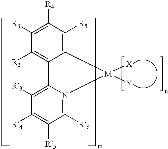
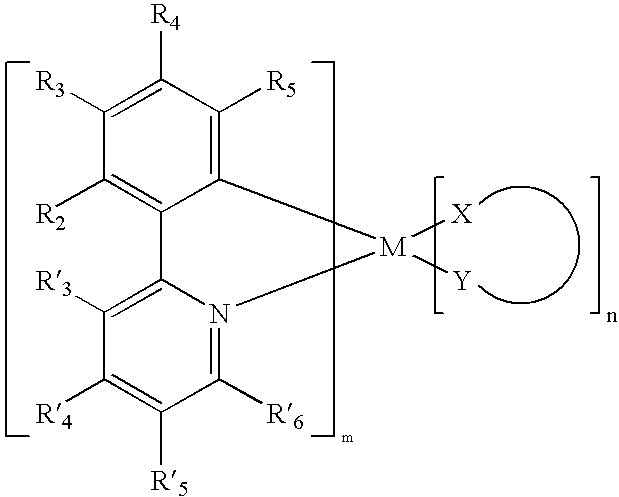
- the present invention comprises a light emitting device including an emissive layer comprising a organometallic compound represented by the following general structure, wherein M is a metal and at least one of R 3 and R 5 is either an electron withdrawing group or an electron donating group, wherein m is an integer from 1 to 4 and n is an integer from 1 to 3, and wherein R′ 4 is an electron withdrawing or an electron donating group such that when neither R 3 or R 5 is an electron withdrawing group then R′ 4 is an electron withdrawing group and when neither R 3 or R 5 is an electron donating group then R! 4 is an electron donating group.
- M is a metal and at least one of R 3 and R 5 is either an electron withdrawing group or an electron donating group
- m is an integer from 1 to 4
- n is an integer from 1 to 3
- R′ 4 is an electron withdrawing or an electron donating group such that when neither R 3 or R 5 is an electron withdrawing group then R′ 4 is an electron withdrawing group and when neither R 3 or R 5 is
- the energy difference between the lowest triplet excited state of the organometallic compound of the present invention and a corresponding relaxed state of the organometallic compound corresponds with a wavelength of less than approximately 520 nm. More preferably the energy difference between the lowest triplet excited state of the organometallic compound of the present invention and a corresponding relaxed state of the organometallic compound corresponds with a wavelength of between approximately 420 nm and approximately 480 nm.
- Alkyl alone or in combination includes linear or branched alkyl groups, preferably C 1 to C 6 alkyl groups, more preferably C 1 to C 3 alkyl groups.
- ITO indium tin oxide
- NPD N,N′-diphenyl-N-N′-di(1-naphthyl)-benzidine
- TPD N,N′-diphenyl-N,N′-di(3-toly)-benzidine
- BAlq aluminum(III)bis(2-methyl-8-quinolinato)4-phenyl- phenolate
- mCP 1,3-N,N-dicarbazole-benzene
- DCM 4-(dicyanoethylene)-6-(4-dimethylaminostyryl-2- methyl)-4H-pyran
- DMQA N,N′-dimethylquinacridone
- PEDOT PSS: an aqueous dispersion of poly(3,4-ethylenedioxythio- phene) with polystyrenesulfonate (PSS)
- the dichlorobridge dimers represented by graphic formula VI can be reacted with a variety of mono-anionic coordinating ligands, e.g. acetonacetyl (acac), picolinic acid, 4-dimethylaminopicolinic acid (DMAPic) and mono-anionic metal-carbon coordination ligands e.g., substituted 2-phenylpyridines, etc and is denoted by X and Y.
- mono-anionic coordinating ligands e.g. acetonacetyl (acac)
- picolinic acid e.g., picolinic acid
- DMAPic 4-dimethylaminopicolinic acid
- mono-anionic metal-carbon coordination ligands e.g., substituted 2-phenylpyridines, etc.
- the final isolated products represented by graphic VII are purified by standard techniques.
- the organic stack consists of, from the anode to the cathode, 100 ⁇ of copper phthalocyanine (CuPc), 300 ⁇ of 4,4′-bis[N-(1-naphthyl)-N-phenylamino]biphenyl ( ⁇ -NPD), 300 ⁇ of Compound C doped with 6 wt % of Compound 11 as the emissive layer (EML), and 300 ⁇ of aluminum(III)bis(2-methyl-8-quinolinato)4-phenylphenolate (BAlq).
- CuPc copper phthalocyanine
- ⁇ -NPD 4,4′-bis[N-(1-naphthyl)-N-phenylamino]biphenyl
- EML emissive layer
- BAlq aluminum(III)bis(2-methyl-8-quinolinato)4-phenylphenolate
- the organic stack consists of, from the anode to the cathode, 100 ⁇ of copper phthalocyanine (CuPc), 450 ⁇ of 4,4′-bis[N-(1-naphthyl)-N-phenylamino]biphenyl ( ⁇ -NPD), 300 ⁇ of compound C doped with 6 wt % of Compound 28 as the emissive layer (EML), and 400 ⁇ of aluminum(III)bis(2-methyl-8-quinolinato)4-phenylphenolate (BAlq).
- CuPc copper phthalocyanine
- ⁇ -NPD 4,4′-bis[N-(1-naphthyl)-N-phenylamino]biphenyl
- EML emissive layer
- BAlq aluminum(III)bis(2-methyl-8-quinolinato)4-phenylphenolate
Abstract

wherein each of the variables are defined herein.
Description

wherein M is a heavy metal with an atomic weight of greater than 40;
- each of R2 through R5 and R′3 through R′6 are independently selected from the group consisting of H, halogens, CN, CF3, CnF2n+1, trifluorovinyl, NO2, CO2R, C(O)R, S(O)R, SO2R, SO3R, P(O)R, PO2R, PO3R, C≡CR, alkyl, alkenyl, aryl, heteroaryl, aryl or heteroaryl groups substituted with halogens, CN, CF3, CnF2n+1, trifluorovinyl, NO2, CO2R, C(O)R, S(O)R, SO2R, SO3R, P(O)R, PO2R, or PO3R, OR, SR, NR2 (including cyclic-amino), PR2 (including cyclic-phosphino), where R is hydrogen, an alkyl group, an aryl group or a heteroaryl group;
- at least one of R3 and R5 is either an electron withdrawing group or an electron donating group;
- m is at least 1, n is at least 0 and X-Y is an ancillary ligand.

is a monoanionic ligand, preferably a non carbon coordinating ligand.

wherein M is a heavy metal with an atomic weight of greater than or equal to 40; m is at least 1; n is at least 0; X-Y is an ancillary ligand; R2 and R4 are both F; R3 is a substituent having a Hammett value less than about −0.17, between about −0.15 and 0.05, or greater than about 0.07; and each of R3, R5 and R′3 through R′6 are independently selected from the group consisting of H, halogens, CN, CF3, CnF2n+1, trifluorovinyl, NO2, CO2R, C(O)R, S(O)R, SO2R, SO3R, P(O)R, PO2R, PO3R, C≡CR, alkyl, alkenyl, aryl, heteroaryl, aryl or heteroaryl groups substituted with halogens, CN, CF3, C,F2n+1, trifluorovinyl, NO2, CO2R, C(O)R, S(O)R, SO2R, SO3R, P(O)R, PO2R, or PO3R; OR, SR, NR2 (including cyclic-amino), PR2 (including cyclic-phosphino), where R is hydrogen, an alkyl group, an aryl group or a heteroaryl group


wherein M is a heavy metal with an atomic weight of greater than 40;
- each of R2 through R5 and R′3 through R′6 are independently selected from the group consisting of H, halogens, CN, CF3, CnF2n+1, trifluorovinyl, NO2, CO2R, C(O)R, S(O)R, SO2R, SO3R, P(O)R, PO2R, PO3R, C≡CR, alkyl, alkenyl, aryl, heteroaryl, aryl or heteroaryl groups substituted with halogens, CN, CF3, CnF2n+1, trifluorovinyl, NO2, CO2R, C(O)R, S(O)R, SO2R, SO3R, P(O)R, PO2R, or PO3R, OR, SR, NR2 (including cyclic-amino), PR2 (including cyclic-phosphino), where R is hydrogen, an alkyl group, an aryl group or a heteroaryl group;
- at least one of R3 and R5 is either an electron withdrawing group or an electron donating group;
- m is at least 1,
- n is at least 0; and,
- X-Y may be an ancillary ligand.

is a monoanionic non carbon coordinating ligand. In this embodiment, the metal is bound to at least one mono-anionic, bidentate, carbon-coordination ligand substituted with electron donating and/or electron withdrawing substituents that shift the emission, relative to the un-substituted ligand, to either the blue, green or red region of the visible spectrum. Further, in this embodiment, the at least one mono-anionic, bidentate, carbon-coordination ligand is substituted with at least one electron withdrawing or electron donating substituent at the R3 or R5 position and the metal is bound to at least one other monoanionic, preferably, non-carbon coordinating ancillary ligand that is different than the first mono-anionic, bidentate, carbon coordination ligand. Preferred ancillary ligands are include those described for formula 2.

wherein M is a metal and at least one of R3 and R5 is either an electron withdrawing group or an electron donating group and wherein m is an integer between 1 and 4 and n is an integer between 1 and 3,; R4 not being F. More specifically, R4 is an electron withdrawing group selected from H, halogens, CN, CF3, CnF2n+1, trifluorovinyl, NO2, CO2R, C(O)R, S(O)R, SO2R, SO3R, P(O)R, PO2R, PO3R, C≡CR, alkyl, alkenyl, aryl, heteroaryl, aryl or heteroaryl groups substituted with halogens, CN, CF3, CnF2n+1, trifluorovinyl, NO2, CO2R, C(O)R, S(O)R, SO2R, SO3R, P(O)R, PO2R, or PO3R or an electron donating group selected from OR, SR, NR2 (including cyclic-amino), PR2 (including cyclic-phosphino), where R is hydrogen, an alkyl group, an aryl group or a heteroaryl group. In preferred embodiments,

is a monoanionic non carbon coordinating ligand

wherein M is a metal and at least one of R3 and R5 is either an electron withdrawing group or an electron donating group, wherein m is an integer from 1 to 4 and n is an integer from 1 to 3, and wherein R′4 is an electron withdrawing or an electron donating group such that when neither R3 or R5 is an electron withdrawing group then R′4 is an electron withdrawing group and when neither R3 or R5 is an electron donating group then R!4 is an electron donating group. In a further preferred embodiment,

is a monoanionic non carbon coordinating ligand

wherein M is a metal and at least one of R3 and R5 is selected from the group consisting of H, halogens, CN, CF3, CnF2n+1, trifluorovinyl, NO2, CO2R, C(O)R, S(O)R, SO2R, SO3R, P(O)R, PO2R, PO3R, C≡CR, alkyl, alkenyl, aryl, heteroaryl, aryl or heteroaryl groups substituted with halogens, CN, CF3, CnF2n+1, trifluorovinyl, NO2, CO2R, C(O)R, S(O)R, SO2R, SO3R, P(O)R, PO2R, or PO3R and wherein m is an integer between 1 and 4 and n is an integer between 1 and 3. In a further preferred embodiment,

is a monoanionic non carbon coordinating ligand.
| CBP: | 4,4′-N,N-dicarbazole-biphenyl |
| m-MTDATA | 4,4′,4″-tris(3-methylphenylphenlyamino)triphenylamine |
| Alq3: | 8-tris-hydroxyquinoline aluminum |
| Bphen: | 4,7-diphenyl-1,10-phenanthroline |
| n-BPhen: | n-doped BPhen (doped with lithium) |
| F4-TCNQ: | tetrafluoro-tetracyano-quinodimethane |
| p-MTDATA: | p-doped m-MTDATA (doped with F4-TCNQ) |
| Ir(ppy)3: | tris(2-phenylpyridine)-iridium |
| Ir(ppz)3: | tris(1-phenylpyrazoloto,N,C(2′)iridium(III) |
| BCP: | 2,9-dimethyl-4,7-diphenyl-1,10-phenanthroline |
| TAZ: | 3-phenyl-4-(1′-naphthyl)-5-phenyl-1,2,4-triazole |
| CuPc: | copper phthalocyanine. |
| ITO: | indium tin oxide |
| NPD: | N,N′-diphenyl-N-N′-di(1-naphthyl)-benzidine |
| TPD: | N,N′-diphenyl-N,N′-di(3-toly)-benzidine |
| BAlq: | aluminum(III)bis(2-methyl-8-quinolinato)4-phenyl- |
| phenolate | |
| mCP: | 1,3-N,N-dicarbazole-benzene |
| DCM: | 4-(dicyanoethylene)-6-(4-dimethylaminostyryl-2- |
| methyl)-4H-pyran | |
| DMQA: | N,N′-dimethylquinacridone |
| PEDOT:PSS: | an aqueous dispersion of poly(3,4-ethylenedioxythio- |
| phene) with polystyrenesulfonate (PSS) | |


| TABLE 1 | |||||||||||||||
| OLED | |||||||||||||||
| max | |||||||||||||||
| (X) | CIE | Emission | efficiency | ||||||||||||
| Example | Device | M | R2 | R3 | R4 | R5 | R′4 | R′5 | R′6 | Ligand | coordinates | (nm) | m | n | (cd/A) |
| A | A | Ir | H | H | H | H | H | H | H | AcAc | (0.33, 0.61) | 520 | 2 | 1 | 20 |
| 1 | 1 | Ir | H | CF3 | H | CF3 | H | H | H | AcAc | (0.19, 0.39) | 472 | 2 | 1 | 17 |
| 2 | Ir | H | CF3 | H | CF3 | H | H | H | Pic | (0.19, 0.39) | 470 | 2 | 1 | ||
| 3 | 3 | Ir | F | H | F | CF3 | H | H | H | AcAc | (0.17, 0.27) | 458 | 2 | 1 | 8.5 |
| 4 | Ir | F | H | F | CF3 | H | H | H | Pic | (0.17, 0.31) | 457 | 2 | 1 | ||
| 5 | Ir | H | CF3 | H | CF3 | OCH3 | H | H | AcAc | (0.17, 0.37) | 468 | 2 | 1 | ||
| 6 | Ir | H | CF3 | H | CF3 | OCH3 | H | H | Pic | (0.18, 0.36) | 466 | 2 | 1 | ||
| 7 | Ir | H | CF3 | H | H | H | H | H | AcAc | (0.31, 0.53) | 510 | 2 | 1 | ||
| 8 | Ir | H | CF3 | H | H | H | H | H | Pic | (0.23, 0.51) | 484 | 2 | 1 | ||
| 9 | Ir | H | H | H | H | H | H | OCH3 | Pic | (0.34, 0.58) | 520 | 2 | 1 | ||
| 10 | Ir | H | CF3 | H | CF3 | N(CH3)2 | H | H | AcAc | (0.18, 0.31) | 463 | 2 | 1 | ||
| 11 | 11 | Ir | H | CF3 | H | CF3 | pyrrolidon | H | H | AcAc | (0.18, 0.29) | 462 | 2 | 1 | 2.7 |
| 12 | Ir | H | CF3 | H | CF3 | pyrrolidon | H | H | DMAPic | (0.21, 0.31) | 456 | 2 | 1 | ||
| 13 | Ir | F | H | F | CF3 | N(CH3)2 | H | H | DMAPic | (0.16, 0.22) | 450 | 2 | 1 | ||
| 14 | Ir | H | CN | H | H | H | H | H | AcAc | (0.26, 0.56) | 500 | 2 | 1 | ||
| 15 | Ir | H | CN | H | H | H | H | H | Pic | (0.22, 0.49) | 482 | 2 | 1 | ||
| 16 | Ir | F | H | H | CF3 | H | H | H | AcAc | (0.19, 0.35) | 468 | 2 | 1 | ||
| 17 | Ir | F | CN | F | H | H | H | H | Pic | 0.15, 0.38 | 452 | 2 | 1 | 11 | |
The organic stack consists of, from the anode to the cathode, 100 Å of copper phthalocyanine (CuPc), 450 Å of 4,4′-bis[N-(1-naphthyl)-N-phenylamino]biphenyl (α-NPD), 300 Å of Compound B doped with 6 wt % of Compound 1 as the emissive layer (EML), and 400 Å of aluminum(III)bis(2-methyl-8-quinolinato)4-phenylphenolate (BAlq).


Alternatively, in Reaction K shown below, one could prepare compounds represented by graphic formula XIV where R3 is a cyano group by the following method. A compound represented by graphic formula XV shown in Reaction K below is reacted at low temperatures with an appropriate base such as lithium diisopropyl amide (LDA) and quenched with carbon dioxide (CO2). Compound XVI is reacted with thionyl chloride and ammonium hydroxide to give X as the carboxamide. Compound XVII is then reacted under dehydrating conditions i.e. acid (H+) to give XVIII. The compound represented by graphic formula XVIII is then converted to the photoactive ligand by replacing XVIII for XI in Reaction H to give III where R3 is now substituted with a cyano substituent.


| TABLE 2 | ||||||
| Peak | OLED | |||||
| ancil- | emis- | maximum | ||||
| Com- | De- | lary | sion | efficiency | ||
| pound | vice | R3 | ligand | (nm) | PL CIE | (cd/A) |
| 18 | 31 | CO2Me | none | 460 | 0.16, 0.29 | 14 |
| (tris) | ||||||
| 19 | 19 | Ph | pic | 474 | 0.17, 0.38 | 12 |
| 20 | 4-CF3Ph | pic | 470 | 0.16, 0.33 | ||
| 21 | 2-pyridine | acac | 482 | 0.17, 0.45 | ||
| 22 | 2-pyridine | pic | 468 | 0.17, 0.34 | ||
| 23 | 2-pyrimidine | acac | 484 | 0.18, 0.46 | ||
| 24 | 2-pyrimidine | pic | 467 | 0.17, 0.33 | ||
| 25 | 4-pyridine | acac | 480 | 0.15, 0.39 | ||
| 26 | 4-pyridine | pic | 468 | 0.17, 0.33 | ||
| 27 | 3-pyridine | pic | 470 | 0.17, 0.33 | ||
| 28 | 28 | CN | pic | 452 | 0.15, 0.19 | 11 |
| 29 | 29 | CN | none | 450 | 0.17, 0.19 | 7 |
| (tris) | ||||||
| 30 | 30 | H | pic | 468 | 0.17, 0.32 | 12 |
| (FIrpic) | ||||||

Claims (73)


Priority Applications (1)
| Application Number | Priority Date | Filing Date | Title |
|---|---|---|---|
| US10/643,413 US7011897B2 (en) | 2002-08-16 | 2003-08-18 | Organic light emitting materials and devices |
Applications Claiming Priority (3)
| Application Number | Priority Date | Filing Date | Title |
|---|---|---|---|
| US40421302P | 2002-08-16 | 2002-08-16 | |
| US10/288,785 US6916554B2 (en) | 2002-11-06 | 2002-11-06 | Organic light emitting materials and devices |
| US10/643,413 US7011897B2 (en) | 2002-08-16 | 2003-08-18 | Organic light emitting materials and devices |
Related Parent Applications (1)
| Application Number | Title | Priority Date | Filing Date |
|---|---|---|---|
| US10/288,785 Continuation-In-Part US6916554B2 (en) | 2002-08-16 | 2002-11-06 | Organic light emitting materials and devices |
Publications (2)
| Publication Number | Publication Date |
|---|---|
| US20040121184A1 US20040121184A1 (en) | 2004-06-24 |
| US7011897B2 true US7011897B2 (en) | 2006-03-14 |
Family
ID=31890991
Family Applications (1)
| Application Number | Title | Priority Date | Filing Date |
|---|---|---|---|
| US10/643,413 Expired - Lifetime US7011897B2 (en) | 2002-08-16 | 2003-08-18 | Organic light emitting materials and devices |
Country Status (7)
| Country | Link |
|---|---|
| US (1) | US7011897B2 (en) |
| EP (1) | EP1534799A4 (en) |
| JP (1) | JP4343838B2 (en) |
| KR (1) | KR20050052473A (en) |
| CN (1) | CN100340630C (en) |
| AU (1) | AU2003263929A1 (en) |
| WO (1) | WO2004016711A1 (en) |
Cited By (15)
| Publication number | Priority date | Publication date | Assignee | Title |
|---|---|---|---|---|
| US20040197602A1 (en) * | 2001-11-07 | 2004-10-07 | Dobbs Kerwin D. | Electroluminescent platinum compounds and devices made with such compounds |
| US20050037233A1 (en) * | 2000-06-30 | 2005-02-17 | Dobbs Kerwin D. | Electroluminescent iridium compounds with fluorinated phenylpyridine ligands, and devices made with such compounds |
| US20050211974A1 (en) * | 2004-03-26 | 2005-09-29 | Thompson Mark E | Organic photosensitive devices |
| US20050260449A1 (en) * | 2004-05-18 | 2005-11-24 | Robert Walters | Complexes with tridentate ligands |
| US20060133437A1 (en) * | 2004-12-21 | 2006-06-22 | Trustees Of Princeton University | Organic injection laser |
| US20060192482A1 (en) * | 2003-08-04 | 2006-08-31 | Tatsuya Igarashi | Organic electroluminescent device |
| US20070122651A1 (en) * | 2003-09-19 | 2007-05-31 | Tatsuya Igarashi | Organic electroluminescent device |
| US20090092854A1 (en) * | 2007-10-04 | 2009-04-09 | Entire Interest | Complexes with tridentate ligands |
| US20090115322A1 (en) * | 2007-10-04 | 2009-05-07 | Walters Robert W | Complexes with tridentate ligands |
| US20100019669A1 (en) * | 2006-12-27 | 2010-01-28 | Nobuhiko Akino | Metal complex, polymer compound and device containing those |
| US20100132770A1 (en) * | 2006-02-09 | 2010-06-03 | Beatty Paul H J | Device including semiconductor nanocrystals and a layer including a doped organic material and methods |
| US7816016B1 (en) | 2003-02-13 | 2010-10-19 | E. I. Du Pont De Nemours And Company | Electroluminescent iridium compounds and devices made therefrom |
| US8865905B2 (en) | 2009-06-26 | 2014-10-21 | General Electric Company | Organic compounds |
| KR101553590B1 (en) | 2013-03-22 | 2015-09-18 | 주식회사 네패스 | Process for the preparation of ligand of blue phosphorescence |
| US10686146B2 (en) | 2017-02-13 | 2020-06-16 | Feng-wen Yen | Paracyclophane-based iridium complexes for organic electroluminescence device |
Families Citing this family (103)
| Publication number | Priority date | Publication date | Assignee | Title |
|---|---|---|---|---|
| KR100493311B1 (en) * | 2001-02-21 | 2005-06-07 | 엘지전자 주식회사 | Watermark-based copy management system and method for digital media copy protection |
| JP4115788B2 (en) * | 2002-09-17 | 2008-07-09 | 日本放送協会 | ORGANIC LIGHT EMITTING MATERIAL, ORGANIC LIGHT EMITTING ELEMENT AND DISPLAY USING THE SAME |
| JP2004281087A (en) * | 2003-03-12 | 2004-10-07 | Nippon Hoso Kyokai <Nhk> | Organic el device and organic el display |
| JP4655454B2 (en) * | 2003-05-28 | 2011-03-23 | コニカミノルタホールディングス株式会社 | Organic electroluminescence element, lighting device and display device |
| JP4363133B2 (en) * | 2003-09-09 | 2009-11-11 | 東洋インキ製造株式会社 | Organic electroluminescent device material and organic electroluminescent device using the same |
| KR100577235B1 (en) | 2004-03-19 | 2006-05-10 | 엘지전자 주식회사 | organic electroluminescence device |
| KR100565666B1 (en) | 2004-03-22 | 2006-03-29 | 엘지전자 주식회사 | organic electroluminescence device |
| KR100556421B1 (en) * | 2004-04-09 | 2006-03-03 | 엘지전자 주식회사 | organic electroluminescence device for blue phosphorescence |
| WO2005124890A1 (en) * | 2004-06-09 | 2005-12-29 | E.I. Dupont De Nemours And Company | Electrolumineschent iridium complex and devices made with such compound |
| KR100730115B1 (en) * | 2004-06-23 | 2007-06-19 | 삼성에스디아이 주식회사 | Iridium compound and organic electroluminescence display employing the same |
| EP3855519A3 (en) * | 2004-07-07 | 2021-09-22 | Universal Display Corporation | Stable and efficient electroluminescent materials |
| US7402345B2 (en) * | 2004-09-14 | 2008-07-22 | E.I. Du Pont De Nemours And Company | Electroluminescent iridium compounds with fluorinated phenylpyridine ligands, and devices made with such compounds |
| DE102004057072A1 (en) * | 2004-11-25 | 2006-06-01 | Basf Ag | Use of Transition Metal Carbene Complexes in Organic Light Emitting Diodes (OLEDs) |
| JP2006213686A (en) * | 2005-02-07 | 2006-08-17 | Idemitsu Kosan Co Ltd | Metal complex compound and organic electroluminescent device using the same |
| US20090123720A1 (en) * | 2005-03-01 | 2009-05-14 | Zhikuan Chen | Solution processed organometallic complexes and their use in electroluminescent devices |
| JP2006241046A (en) * | 2005-03-02 | 2006-09-14 | Chemiprokasei Kaisha Ltd | Cyanophenylpyridine iridium complex, luminescent material comprising the same and organic el device containing the same |
| WO2006098120A1 (en) * | 2005-03-16 | 2006-09-21 | Konica Minolta Holdings, Inc. | Organic electroluminescent device material and organic electroluminescent device |
| KR101223717B1 (en) * | 2005-04-12 | 2013-01-18 | 삼성디스플레이 주식회사 | Silyl substituted cyclometalated transition metal complex and organic electroluminescence device using the same |
| KR100611885B1 (en) * | 2005-04-21 | 2006-08-11 | 삼성에스디아이 주식회사 | Organic metal compounds which the compound for host and the compound for dopant were connected, organic electroluminescence display devices using the compounds and method for preparation of the devices |
| US8039124B2 (en) * | 2005-06-30 | 2011-10-18 | Koninklijke Philips Electronics N.V. | Electro luminescent metal complexes |
| US20090039771A1 (en) | 2005-07-01 | 2009-02-12 | Konica Minolta Holdings, Inc. | Organic electroluminescent element material, organic electroluminescent element, display device and lighting device |
| KR100729089B1 (en) * | 2005-08-26 | 2007-06-14 | 삼성에스디아이 주식회사 | Organic light emitting display and method for fabricating the same |
| WO2007029466A1 (en) | 2005-09-06 | 2007-03-15 | Konica Minolta Holdings, Inc. | Organic electroluminescent device, display and illuminating device |
| TW200722500A (en) * | 2005-10-07 | 2007-06-16 | Solvay | Light-emitting material |
| WO2007047779A1 (en) * | 2005-10-14 | 2007-04-26 | University Of Florida Research Foundation, Inc. | Method and apparatus for light emission utilizing an oled with a microcavity |
| GB2433509A (en) * | 2005-12-22 | 2007-06-27 | Cambridge Display Tech Ltd | Arylamine polymer |
| EP1803789A1 (en) | 2005-12-28 | 2007-07-04 | Novaled AG | Use of metal complexes as emitters in organic light emitting devices and such a device |
| DE112007000789B4 (en) | 2006-03-30 | 2012-03-15 | Novaled Ag | Use of Bora tetraazepentalene |
| US20070247061A1 (en) * | 2006-04-20 | 2007-10-25 | Vadim Adamovich | Multiple dopant emissive layer OLEDs |
| US9118020B2 (en) * | 2006-04-27 | 2015-08-25 | Global Oled Technology Llc | Electroluminescent devices including organic eil layer |
| EP1860709B1 (en) | 2006-05-24 | 2012-08-08 | Novaled AG | Use of square planar transition metal complexes as dopants |
| DE102006030860A1 (en) | 2006-07-04 | 2008-01-10 | Universität Regensburg | Oligomers of isonitrile metal complexes as triplet emitters for OLED applications |
| DE102006035018B4 (en) | 2006-07-28 | 2009-07-23 | Novaled Ag | Oxazole triplet emitter for OLED applications |
| JP4909695B2 (en) | 2006-09-27 | 2012-04-04 | 富士フイルム株式会社 | Organic electroluminescence device |
| JP2008108709A (en) * | 2006-09-28 | 2008-05-08 | Fujifilm Corp | Organic electroluminescent element |
| DE102006051975B4 (en) | 2006-11-03 | 2012-04-19 | Merck Patent Gmbh | Photophysical OLED efficiency increase |
| US8115378B2 (en) * | 2006-12-28 | 2012-02-14 | E. I. Du Pont De Nemours And Company | Tetra-substituted chrysenes for luminescent applications |
| DE102007002420A1 (en) | 2007-01-17 | 2008-07-24 | Universität Regensburg | Polymeric anions / cations |
| US20080217582A1 (en) * | 2007-03-08 | 2008-09-11 | Yun Chi | Class of luminescent iridium(iii) complexes with 2-(diphenylphosphino)phenolate ligand and organic electroluminescent device thereof |
| US20080284317A1 (en) * | 2007-05-17 | 2008-11-20 | Liang-Sheng Liao | Hybrid oled having improved efficiency |
| US20080284318A1 (en) * | 2007-05-17 | 2008-11-20 | Deaton Joseph C | Hybrid fluorescent/phosphorescent oleds |
| JP5484690B2 (en) | 2007-05-18 | 2014-05-07 | ユー・ディー・シー アイルランド リミテッド | Organic electroluminescence device |
| WO2008150940A1 (en) * | 2007-06-01 | 2008-12-11 | E. I. Du Pont De Nemours And Company | Chrysenes for green luminescent applications |
| JP5466150B2 (en) | 2007-06-01 | 2014-04-09 | イー・アイ・デュポン・ドウ・ヌムール・アンド・カンパニー | Green light emitting material |
| KR101554750B1 (en) * | 2007-06-01 | 2015-09-22 | 이 아이 듀폰 디 네모아 앤드 캄파니 | Chrysenes for deep blue luminescent applications |
| TW200907021A (en) * | 2007-06-01 | 2009-02-16 | Du Pont | Blue luminescent materials |
| US8034465B2 (en) * | 2007-06-20 | 2011-10-11 | Global Oled Technology Llc | Phosphorescent oled having double exciton-blocking layers |
| WO2009026235A2 (en) * | 2007-08-17 | 2009-02-26 | Georgia Tech Research Corporation | Norbornene-based copolymers with iridium complexes and exiton transport groups in their side-chains and use thereof |
| JP5115094B2 (en) * | 2007-08-21 | 2013-01-09 | コニカミノルタホールディングス株式会社 | ORGANIC ELECTROLUMINESCENT ELEMENT MATERIAL, ORGANIC ELECTROLUMINESCENT ELEMENT, DISPLAY DEVICE AND LIGHTING DEVICE |
| JP2009076865A (en) | 2007-08-29 | 2009-04-09 | Fujifilm Corp | Organic electroluminescence device |
| TWI419876B (en) * | 2007-12-06 | 2013-12-21 | Universal Display Corp | Method for the synthesis of iridium (iii) complexes with sterically demanding ligands |
| US20090191427A1 (en) * | 2008-01-30 | 2009-07-30 | Liang-Sheng Liao | Phosphorescent oled having double hole-blocking layers |
| JP2010031250A (en) * | 2008-06-23 | 2010-02-12 | Sumitomo Chemical Co Ltd | Composition and light-emitting element using the composition |
| JP5556063B2 (en) * | 2008-06-23 | 2014-07-23 | 住友化学株式会社 | Composition and light-emitting device using the composition |
| JP5609022B2 (en) * | 2008-06-23 | 2014-10-22 | 住友化学株式会社 | Polymer compound containing residue of metal complex and device using the same |
| WO2010027583A1 (en) * | 2008-09-03 | 2010-03-11 | Universal Display Corporation | Phosphorescent materials |
| TWI555734B (en) * | 2008-09-16 | 2016-11-01 | 環球展覽公司 | Phosphorescent materials |
| DE102008048336A1 (en) | 2008-09-22 | 2010-03-25 | Merck Patent Gmbh | Mononuclear neutral copper (I) complexes and their use for the production of optoelectronic devices |
| US8119037B2 (en) | 2008-10-16 | 2012-02-21 | Novaled Ag | Square planar transition metal complexes and organic semiconductive materials using them as well as electronic or optoelectric components |
| DE102008053121A1 (en) | 2008-10-24 | 2010-04-29 | Merck Patent Gmbh | Double complex salts as emitters in OLED devices |
| US20110215715A1 (en) * | 2008-11-19 | 2011-09-08 | E.I. Du Pont De Nemours And Company | Chrysene compounds for blue or green luminescent applications |
| JP5591822B2 (en) * | 2008-12-12 | 2014-09-17 | イー・アイ・デュポン・ドウ・ヌムール・アンド・カンパニー | Photoactive composition and electronic device formed with the composition |
| US8263973B2 (en) * | 2008-12-19 | 2012-09-11 | E I Du Pont De Nemours And Company | Anthracene compounds for luminescent applications |
| US8932733B2 (en) * | 2008-12-19 | 2015-01-13 | E I Du Pont De Nemours And Company | Chrysene derivative host materials |
| US8531100B2 (en) | 2008-12-22 | 2013-09-10 | E I Du Pont De Nemours And Company | Deuterated compounds for luminescent applications |
| JP2012517422A (en) | 2009-02-06 | 2012-08-02 | ソルヴェイ(ソシエテ アノニム) | Phosphorescent luminescent iridium complexes containing pyridyltriazole ligands |
| US8759818B2 (en) | 2009-02-27 | 2014-06-24 | E I Du Pont De Nemours And Company | Deuterated compounds for electronic applications |
| WO2010114583A1 (en) * | 2009-04-03 | 2010-10-07 | E. I. Du Pont De Nemours And Company | Electroactive materials |
| KR101610226B1 (en) | 2009-04-22 | 2016-04-08 | 한국생산기술연구원 | Metal complex containing carbazoles connected Phenyl-pyridine, it's preparation method and it's applications |
| KR101610235B1 (en) | 2009-05-06 | 2016-04-08 | 한국생산기술연구원 | Metal complex containing phenyl-pyridines connected to carbazoles, it's preparation method and it's applications |
| EP2669351A1 (en) | 2009-05-19 | 2013-12-04 | E. I. du Pont de Nemours and Company | Chrysene compounds for luminescent applications |
| DE102009030475A1 (en) | 2009-06-24 | 2011-01-05 | Hartmut Prof. Dr. Yersin | Copper complexes for optoelectronic applications |
| CN102471677A (en) | 2009-07-01 | 2012-05-23 | E.I.内穆尔杜邦公司 | Chrysene compounds for luminescent applications |
| US8968883B2 (en) * | 2009-08-13 | 2015-03-03 | E I Du Pont De Nemours And Company | Chrysene derivative materials |
| US8993754B2 (en) | 2009-08-27 | 2015-03-31 | National Institute Of Advanced Industrial Science And Technology | Iridium complex and light emitting material formed from same |
| KR101790854B1 (en) * | 2009-09-29 | 2017-10-26 | 이 아이 듀폰 디 네모아 앤드 캄파니 | Deuterated compounds for luminescent applications |
| TW201114771A (en) | 2009-10-29 | 2011-05-01 | Du Pont | Deuterated compounds for electronic applications |
| CN102648203B (en) * | 2009-11-30 | 2015-09-30 | 三星电子株式会社 | Iridium complex, organic electroluminescent device and uses thereof |
| JP5596966B2 (en) | 2009-12-08 | 2014-09-24 | キヤノン株式会社 | Novel iridium complex and organic light emitting device having the same |
| JP2011121876A (en) | 2009-12-08 | 2011-06-23 | Canon Inc | New iridium complex and organic light-emitting device containing the same |
| US8617720B2 (en) | 2009-12-21 | 2013-12-31 | E I Du Pont De Nemours And Company | Electroactive composition and electronic device made with the composition |
| US9175211B2 (en) * | 2010-03-03 | 2015-11-03 | Universal Display Corporation | Phosphorescent materials |
| US9293716B2 (en) | 2010-12-20 | 2016-03-22 | Ei Du Pont De Nemours And Company | Compositions for electronic applications |
| EP2762483A1 (en) | 2011-09-12 | 2014-08-06 | Nippon Steel & Sumikin Chemical Co., Ltd. | Organic electroluminescent element material having silicon-containing four membered ring structure, and organic electroluminescent element |
| JP5914500B2 (en) | 2011-09-12 | 2016-05-11 | 新日鉄住金化学株式会社 | Organic electroluminescence device |
| US9142785B2 (en) | 2011-09-12 | 2015-09-22 | Nippon Steel & Sumikin Chemical Co., Ltd. | Organic electroluminescent element |
| EP2594571A1 (en) | 2011-11-16 | 2013-05-22 | Cynora GmbH | Copper complexes for optoelectronic applications |
| CN102558238A (en) * | 2011-12-06 | 2012-07-11 | 吉林大学 | Iridium complexes containing guanidine group and application of iridium complexes to preparation of electroluminescent devices |
| EP2793280B1 (en) | 2011-12-12 | 2017-03-29 | Nippon Steel & Sumikin Chemical Co., Ltd. | Organic electroluminescent element material and organic electroluminescent element using same |
| US9985219B2 (en) | 2012-03-12 | 2018-05-29 | Nippon Steel & Sumikin Chemical Co., Ltd. | Organic electroluminescent element |
| TW201345917A (en) * | 2012-05-09 | 2013-11-16 | Nat Univ Tsing Hua | Phenylsilyl phosphine and iridium complex made from said phenylsilyl phosphine |
| CN104396042B (en) | 2012-06-28 | 2016-10-12 | 新日铁住金化学株式会社 | Material for organic electroluminescence device and organic electroluminescent device |
| WO2014013936A1 (en) | 2012-07-19 | 2014-01-23 | 新日鉄住金化学株式会社 | Organic electroluminescent element |
| TWI599570B (en) | 2012-09-28 | 2017-09-21 | 新日鐵住金化學股份有限公司 | Compounds for organic electroluminescent devices and organic electroluminescent devices |
| JP6357422B2 (en) | 2012-12-17 | 2018-07-11 | 新日鉄住金化学株式会社 | Organic electroluminescence device |
| KR102153043B1 (en) | 2014-01-07 | 2020-09-07 | 삼성전자주식회사 | Organometallic compound and organic light emitting device including the same |
| WO2016055557A1 (en) | 2014-10-08 | 2016-04-14 | Cynora Gmbh | Metal complexes with tridentate ligands for optoelectronic applications |
| US10153441B2 (en) * | 2015-03-30 | 2018-12-11 | Industrial Technology Research Institute | Organic metal compound, organic light-emitting device, and lighting device employing the same |
| CN111868955A (en) | 2018-03-19 | 2020-10-30 | 日铁化学材料株式会社 | Organic electroluminescent element |
| CN117402190A (en) | 2019-02-01 | 2024-01-16 | 北京夏禾科技有限公司 | Organic luminescent material containing cyano-substituted ligand |
| CN113816996A (en) | 2020-06-20 | 2021-12-21 | 北京夏禾科技有限公司 | Phosphorescent organic metal complex and application thereof |
| CN113816997A (en) | 2020-06-20 | 2021-12-21 | 北京夏禾科技有限公司 | Phosphorescent organic metal complex and application thereof |
| US20220162244A1 (en) | 2020-11-18 | 2022-05-26 | Beijing Summer Sprout Technology Co., Ltd. | Organic electroluminescent material and device thereof |
Citations (22)
| Publication number | Priority date | Publication date | Assignee | Title |
|---|---|---|---|---|
| US4769292A (en) | 1987-03-02 | 1988-09-06 | Eastman Kodak Company | Electroluminescent device with modified thin film luminescent zone |
| US5247190A (en) | 1989-04-20 | 1993-09-21 | Cambridge Research And Innovation Limited | Electroluminescent devices |
| US5703436A (en) | 1994-12-13 | 1997-12-30 | The Trustees Of Princeton University | Transparent contacts for organic devices |
| US5707745A (en) | 1994-12-13 | 1998-01-13 | The Trustees Of Princeton University | Multicolor organic light emitting devices |
| US5834893A (en) | 1996-12-23 | 1998-11-10 | The Trustees Of Princeton University | High efficiency organic light emitting devices with light directing structures |
| US5844363A (en) | 1997-01-23 | 1998-12-01 | The Trustees Of Princeton Univ. | Vacuum deposited, non-polymeric flexible organic light emitting devices |
| US6013982A (en) | 1996-12-23 | 2000-01-11 | The Trustees Of Princeton University | Multicolor display devices |
| US6087196A (en) | 1998-01-30 | 2000-07-11 | The Trustees Of Princeton University | Fabrication of organic semiconductor devices using ink jet printing |
| US6091195A (en) | 1997-02-03 | 2000-07-18 | The Trustees Of Princeton University | Displays having mesa pixel configuration |
| US6097147A (en) | 1998-09-14 | 2000-08-01 | The Trustees Of Princeton University | Structure for high efficiency electroluminescent device |
| US6294398B1 (en) | 1999-11-23 | 2001-09-25 | The Trustees Of Princeton University | Method for patterning devices |
| US6303238B1 (en) | 1997-12-01 | 2001-10-16 | The Trustees Of Princeton University | OLEDs doped with phosphorescent compounds |
| US6337102B1 (en) | 1997-11-17 | 2002-01-08 | The Trustees Of Princeton University | Low pressure vapor phase deposition of organic thin films |
| WO2002002714A2 (en) | 2000-06-30 | 2002-01-10 | E.I. Du Pont De Nemours And Company | Electroluminescent iridium compounds with fluorinated phenylpyridines, phenylpyrimidines, and phenylquinolines and devices made with such compounds |
| WO2002015645A1 (en) | 2000-08-11 | 2002-02-21 | The Trustees Of Princeton University | Organometallic compounds and emission-shifting organic electrophosphorescence |
| US20020024293A1 (en) | 2000-07-17 | 2002-02-28 | Fuji Photo Film Co., Ltd. | Light-emitting element and iridium complex |
| US20020028329A1 (en) | 2000-07-17 | 2002-03-07 | Fuji Photo Film Co., Ltd. | Light emitting element and azole compound |
| EP1191613A2 (en) | 2000-09-26 | 2002-03-27 | Canon Kabushiki Kaisha | Luminescence device, display apparatus and metal coordination compound |
| US20030059646A1 (en) * | 2000-11-30 | 2003-03-27 | Canon Kabushiki Kaisha | Luminescence device and display apparatus |
| US20030108771A1 (en) * | 2001-11-07 | 2003-06-12 | Lecloux Daniel David | Electroluminescent platinum compounds and devices made with such compounds |
| US20030230980A1 (en) | 2002-06-18 | 2003-12-18 | Forrest Stephen R | Very low voltage, high efficiency phosphorescent oled in a p-i-n structure |
| US20040174116A1 (en) | 2001-08-20 | 2004-09-09 | Lu Min-Hao Michael | Transparent electrodes |
Family Cites Families (9)
| Publication number | Priority date | Publication date | Assignee | Title |
|---|---|---|---|---|
| US570436A (en) * | 1896-10-27 | Means for controlling flow of liquids | ||
| JP3445315B2 (en) * | 1992-07-13 | 2003-09-08 | イーストマン コダック カンパニー | Aluminum chelate compound and internal junction type organic electroluminescent device |
| JP4340401B2 (en) * | 2000-07-17 | 2009-10-07 | 富士フイルム株式会社 | Light emitting device and iridium complex |
| JP4285947B2 (en) * | 2001-06-15 | 2009-06-24 | 三洋電機株式会社 | Luminescent organometallic compound and light emitting device |
| JP2003123982A (en) * | 2001-08-07 | 2003-04-25 | Fuji Photo Film Co Ltd | Light emitting element and novel iridium complex |
| JP2003073387A (en) * | 2001-09-04 | 2003-03-12 | Canon Inc | Metal coordination compound and organic luminescent element |
| JP5135660B2 (en) * | 2001-09-27 | 2013-02-06 | コニカミノルタホールディングス株式会社 | Organic electroluminescence device |
| JP2003253128A (en) * | 2002-02-28 | 2003-09-10 | Jsr Corp | Luminescent composition |
| DE10215010A1 (en) * | 2002-04-05 | 2003-10-23 | Covion Organic Semiconductors | Rhodium and iridium complexes |
-
2003
- 2003-08-18 WO PCT/US2003/025938 patent/WO2004016711A1/en active Application Filing
- 2003-08-18 KR KR1020057002654A patent/KR20050052473A/en not_active Application Discontinuation
- 2003-08-18 AU AU2003263929A patent/AU2003263929A1/en not_active Abandoned
- 2003-08-18 JP JP2004529129A patent/JP4343838B2/en not_active Expired - Lifetime
- 2003-08-18 US US10/643,413 patent/US7011897B2/en not_active Expired - Lifetime
- 2003-08-18 EP EP03788646A patent/EP1534799A4/en not_active Withdrawn
- 2003-08-18 CN CNB038223813A patent/CN100340630C/en not_active Expired - Lifetime
Patent Citations (24)
| Publication number | Priority date | Publication date | Assignee | Title |
|---|---|---|---|---|
| US4769292A (en) | 1987-03-02 | 1988-09-06 | Eastman Kodak Company | Electroluminescent device with modified thin film luminescent zone |
| US5247190A (en) | 1989-04-20 | 1993-09-21 | Cambridge Research And Innovation Limited | Electroluminescent devices |
| US5703436A (en) | 1994-12-13 | 1997-12-30 | The Trustees Of Princeton University | Transparent contacts for organic devices |
| US5707745A (en) | 1994-12-13 | 1998-01-13 | The Trustees Of Princeton University | Multicolor organic light emitting devices |
| US5834893A (en) | 1996-12-23 | 1998-11-10 | The Trustees Of Princeton University | High efficiency organic light emitting devices with light directing structures |
| US6013982A (en) | 1996-12-23 | 2000-01-11 | The Trustees Of Princeton University | Multicolor display devices |
| US5844363A (en) | 1997-01-23 | 1998-12-01 | The Trustees Of Princeton Univ. | Vacuum deposited, non-polymeric flexible organic light emitting devices |
| US6091195A (en) | 1997-02-03 | 2000-07-18 | The Trustees Of Princeton University | Displays having mesa pixel configuration |
| US6337102B1 (en) | 1997-11-17 | 2002-01-08 | The Trustees Of Princeton University | Low pressure vapor phase deposition of organic thin films |
| US6303238B1 (en) | 1997-12-01 | 2001-10-16 | The Trustees Of Princeton University | OLEDs doped with phosphorescent compounds |
| US6087196A (en) | 1998-01-30 | 2000-07-11 | The Trustees Of Princeton University | Fabrication of organic semiconductor devices using ink jet printing |
| US6097147A (en) | 1998-09-14 | 2000-08-01 | The Trustees Of Princeton University | Structure for high efficiency electroluminescent device |
| US6294398B1 (en) | 1999-11-23 | 2001-09-25 | The Trustees Of Princeton University | Method for patterning devices |
| US6468819B1 (en) | 1999-11-23 | 2002-10-22 | The Trustees Of Princeton University | Method for patterning organic thin film devices using a die |
| US20020121638A1 (en) * | 2000-06-30 | 2002-09-05 | Vladimir Grushin | Electroluminescent iridium compounds with fluorinated phenylpyridines, phenylpyrimidines, and phenylquinolines and devices made with such compounds |
| WO2002002714A2 (en) | 2000-06-30 | 2002-01-10 | E.I. Du Pont De Nemours And Company | Electroluminescent iridium compounds with fluorinated phenylpyridines, phenylpyrimidines, and phenylquinolines and devices made with such compounds |
| US20020024293A1 (en) | 2000-07-17 | 2002-02-28 | Fuji Photo Film Co., Ltd. | Light-emitting element and iridium complex |
| US20020028329A1 (en) | 2000-07-17 | 2002-03-07 | Fuji Photo Film Co., Ltd. | Light emitting element and azole compound |
| WO2002015645A1 (en) | 2000-08-11 | 2002-02-21 | The Trustees Of Princeton University | Organometallic compounds and emission-shifting organic electrophosphorescence |
| EP1191613A2 (en) | 2000-09-26 | 2002-03-27 | Canon Kabushiki Kaisha | Luminescence device, display apparatus and metal coordination compound |
| US20030059646A1 (en) * | 2000-11-30 | 2003-03-27 | Canon Kabushiki Kaisha | Luminescence device and display apparatus |
| US20040174116A1 (en) | 2001-08-20 | 2004-09-09 | Lu Min-Hao Michael | Transparent electrodes |
| US20030108771A1 (en) * | 2001-11-07 | 2003-06-12 | Lecloux Daniel David | Electroluminescent platinum compounds and devices made with such compounds |
| US20030230980A1 (en) | 2002-06-18 | 2003-12-18 | Forrest Stephen R | Very low voltage, high efficiency phosphorescent oled in a p-i-n structure |
Non-Patent Citations (13)
| Title |
|---|
| A.J. Bridges et al., "A Dramatic Solvent Effect during Aromatic Halogen-Metal Exchanges. Different Products from Lithlation of Polyfluorobromobenzenes in Ether and THF", J. Org. Chem., vol. 55, pp. 773-775, Jan. 5, 1990. |
| C. Adachi et al., "Nearly 100% internal phosphorescence efficiency in an organic light emitting device", J. Appl. Phys. 90, pp. 5048-5051 (Nov. 2001). |
| C. Hansch, et al., "A Survey of Hammett Substituent Constants and Resonance and Field Parameters", Chem. Rev. 1991, 91, pp. 165-195. |
| D. Cuperly et al., "First Direct C-2-Lithiation of 4-DMAP. Convenient Access to Reactive Functional Derivatives and Ligands", J. Org. Chem. 2002, vol. 67, No. 1, pp. 238-241, Jan. 11, 2002. |
| H, J, A, Dartnall, J.K. Bowmaker, and J.D. Mollon, Proc. Roy. Soc. B. (London), 1983, 220, 115-130. |
| H. Zollinger, "Color Chemistry" VCH Publishers, 1991. |
| M.A. Baldo et al., "Highly efficient phosphorescent emission from organic Electroluminescent devices," Nature, Sep. 1998, vol. 395, pp. 151-154. |
| M.A. Baldo et al., "Very high-efficiency green organic light-emitting devices based on electrophosphorescence", Applied Physics Letters, vol. 75, No., 1, pp. 4-6, Jul. 5, 1999. |
| N. Miyaura, et al., "Palladium-Catalyzed Cross-Coupling Reactions of Organoboron Compounds", Chem, Rev. 1995, vol. 95, No. 7, pp. 2457-2483, Nov. 1995. |
| P.L. Coe et al., "The lithiation of fluorinated benzenes and its dependence on solvent and temperature", J. Chem. Soc. Perkin Trans. I, pp. 2729-2737, 1995. |
| Thomas H. Lowry et al., Mechanism and Theory in Organic Chemistry, Third Edition, New York, Harper & Row publishers, pp. 143-151, 1997. |
| U.S. Appl. No. 60/215,362. * |
| U.S. Appl. No. 60/347,910. * |
Cited By (27)
| Publication number | Priority date | Publication date | Assignee | Title |
|---|---|---|---|---|
| US20070292713A9 (en) * | 2000-06-30 | 2007-12-20 | Dobbs Kerwin D | Electroluminescent iridium compounds with fluorinated phenylpyridine ligands, and devices made with such compounds |
| US20050037233A1 (en) * | 2000-06-30 | 2005-02-17 | Dobbs Kerwin D. | Electroluminescent iridium compounds with fluorinated phenylpyridine ligands, and devices made with such compounds |
| US7476452B2 (en) * | 2000-06-30 | 2009-01-13 | E. I. Du Pont De Nemours And Company | Electroluminescent iridium compounds with fluorinated phenylpyridine ligands, and devices made with such compounds |
| US20040197602A1 (en) * | 2001-11-07 | 2004-10-07 | Dobbs Kerwin D. | Electroluminescent platinum compounds and devices made with such compounds |
| US7320833B2 (en) * | 2001-11-07 | 2008-01-22 | E.I. Du Pont De Nemours And Company | Electroluminescent platinum compounds and devices made with such compounds |
| US7816016B1 (en) | 2003-02-13 | 2010-10-19 | E. I. Du Pont De Nemours And Company | Electroluminescent iridium compounds and devices made therefrom |
| US7737624B2 (en) | 2003-08-04 | 2010-06-15 | Fujifilm Corporation | Organic electroluminescent device |
| US20060192482A1 (en) * | 2003-08-04 | 2006-08-31 | Tatsuya Igarashi | Organic electroluminescent device |
| US20070122651A1 (en) * | 2003-09-19 | 2007-05-31 | Tatsuya Igarashi | Organic electroluminescent device |
| US7935432B2 (en) * | 2003-09-19 | 2011-05-03 | Fujifilm Corporation | Organic electroluminescent device |
| US20100000606A1 (en) * | 2004-03-26 | 2010-01-07 | Thompson Mark E | Organic photosensitive devices |
| US20050211974A1 (en) * | 2004-03-26 | 2005-09-29 | Thompson Mark E | Organic photosensitive devices |
| US7279704B2 (en) * | 2004-05-18 | 2007-10-09 | The University Of Southern California | Complexes with tridentate ligands |
| US20050260449A1 (en) * | 2004-05-18 | 2005-11-24 | Robert Walters | Complexes with tridentate ligands |
| US7242703B2 (en) * | 2004-12-21 | 2007-07-10 | The Trustees Of Princeton University | Organic injection laser |
| US20060133437A1 (en) * | 2004-12-21 | 2006-06-22 | Trustees Of Princeton University | Organic injection laser |
| US20100132770A1 (en) * | 2006-02-09 | 2010-06-03 | Beatty Paul H J | Device including semiconductor nanocrystals and a layer including a doped organic material and methods |
| TWI417290B (en) * | 2006-12-27 | 2013-12-01 | Sumitomo Chemical Co | Metal complex, polymer compound, and devices comprising the same |
| US8608986B2 (en) | 2006-12-27 | 2013-12-17 | Sumitomo Chemical Company, Limited | Metal complex, polymer compound and device containing those |
| US20100019669A1 (en) * | 2006-12-27 | 2010-01-28 | Nobuhiko Akino | Metal complex, polymer compound and device containing those |
| US20090115322A1 (en) * | 2007-10-04 | 2009-05-07 | Walters Robert W | Complexes with tridentate ligands |
| US8383249B2 (en) | 2007-10-04 | 2013-02-26 | Universal Display Corporation | Complexes with tridentate ligands |
| US8067100B2 (en) | 2007-10-04 | 2011-11-29 | Universal Display Corporation | Complexes with tridentate ligands |
| US20090092854A1 (en) * | 2007-10-04 | 2009-04-09 | Entire Interest | Complexes with tridentate ligands |
| US8865905B2 (en) | 2009-06-26 | 2014-10-21 | General Electric Company | Organic compounds |
| KR101553590B1 (en) | 2013-03-22 | 2015-09-18 | 주식회사 네패스 | Process for the preparation of ligand of blue phosphorescence |
| US10686146B2 (en) | 2017-02-13 | 2020-06-16 | Feng-wen Yen | Paracyclophane-based iridium complexes for organic electroluminescence device |
Also Published As
| Publication number | Publication date |
|---|---|
| CN1681904A (en) | 2005-10-12 |
| CN100340630C (en) | 2007-10-03 |
| EP1534799A1 (en) | 2005-06-01 |
| JP2006513278A (en) | 2006-04-20 |
| WO2004016711A1 (en) | 2004-02-26 |
| US20040121184A1 (en) | 2004-06-24 |
| EP1534799A4 (en) | 2008-02-27 |
| AU2003263929A8 (en) | 2004-03-03 |
| KR20050052473A (en) | 2005-06-02 |
| AU2003263929A1 (en) | 2004-03-03 |
| JP4343838B2 (en) | 2009-10-14 |
Similar Documents
| Publication | Publication Date | Title |
|---|---|---|
| US7011897B2 (en) | Organic light emitting materials and devices | |
| US20200388773A1 (en) | Phenyl and Fluorenyl Substituted Phenyl-Pyrazole Complexesof Ir | |
| US6916554B2 (en) | Organic light emitting materials and devices | |
| US6858327B2 (en) | Organic light emitting materials and devices | |
| JP5577370B2 (en) | Stable and efficient electroluminescent material | |
| US7429426B2 (en) | Organometallic compounds for use in electroluminescent devices | |
| EP1561240B1 (en) | Organic light emitting materials and devices | |
| EP1711579B1 (en) | Improved electroluminescent stability | |
| US7482451B2 (en) | Organic light emitting materials with anionic ligand | |
| US8449990B2 (en) | Electroluminescent efficiency | |
| US20050170206A1 (en) | OLEDs utilizing multidentate ligand systems | |
| JP2006513278A6 (en) | Organic light emitting materials and devices | |
| US20060008671A1 (en) | Electroluminescent efficiency | |
| KR101275809B1 (en) | Cyclometalated transition metal complex and organic electroluminescence device using the same | |
| Beach et al. | Thompson ct al. |
Legal Events
| Date | Code | Title | Description |
|---|---|---|---|
| AS | Assignment |
Owner name: UNIVERSAL DISPLAY CORPORATION, NEW JERSEY Free format text: ASSIGNMENT OF ASSIGNORS INTEREST;ASSIGNORS:KWONG, RAYMOND;TUNG, YEH-JIUM;KNOWLES, DAVID B.;AND OTHERS;REEL/FRAME:014923/0021;SIGNING DATES FROM 20030102 TO 20031210 Owner name: SOUTHERN CALIFORNIA, UNIVERSITY OF, THE, CALIFORNI Free format text: ASSIGNMENT OF ASSIGNORS INTEREST;ASSIGNORS:THOMPSON, MARK E.;DJUROVICH, PETER;REEL/FRAME:014922/0939;SIGNING DATES FROM 20040109 TO 20040112 |
|
| AS | Assignment |
Owner name: UNIVERSAL DISPLAY CORPORATION, NEW JERSEY Free format text: ASSIGNMENT OF ASSIGNORS INTEREST;ASSIGNOR:MA, BIN;REEL/FRAME:015186/0099 Effective date: 20040315 |
|
| STCF | Information on status: patent grant |
Free format text: PATENTED CASE |
|
| FPAY | Fee payment |
Year of fee payment: 4 |
|
| FEPP | Fee payment procedure |
Free format text: PAYOR NUMBER ASSIGNED (ORIGINAL EVENT CODE: ASPN); ENTITY STATUS OF PATENT OWNER: LARGE ENTITY |
|
| FPAY | Fee payment |
Year of fee payment: 8 |
|
| MAFP | Maintenance fee payment |
Free format text: PAYMENT OF MAINTENANCE FEE, 12TH YEAR, LARGE ENTITY (ORIGINAL EVENT CODE: M1553) Year of fee payment: 12 |