US6940988B1 - Semi-permanent canal hearing device - Google Patents
Semi-permanent canal hearing device Download PDFInfo
- Publication number
- US6940988B1 US6940988B1 US09/199,669 US19966998A US6940988B1 US 6940988 B1 US6940988 B1 US 6940988B1 US 19966998 A US19966998 A US 19966998A US 6940988 B1 US6940988 B1 US 6940988B1
- Authority
- US
- United States
- Prior art keywords
- semi
- hearing device
- assembly
- permanent hearing
- canal
- Prior art date
- Legal status (The legal status is an assumption and is not a legal conclusion. Google has not performed a legal analysis and makes no representation as to the accuracy of the status listed.)
- Expired - Fee Related
Links
Images


Classifications
-
- H—ELECTRICITY
- H04—ELECTRIC COMMUNICATION TECHNIQUE
- H04R—LOUDSPEAKERS, MICROPHONES, GRAMOPHONE PICK-UPS OR LIKE ACOUSTIC ELECTROMECHANICAL TRANSDUCERS; DEAF-AID SETS; PUBLIC ADDRESS SYSTEMS
- H04R25/00—Deaf-aid sets, i.e. electro-acoustic or electro-mechanical hearing aids; Electric tinnitus maskers providing an auditory perception
- H04R25/60—Mounting or interconnection of hearing aid parts, e.g. inside tips, housings or to ossicles
- H04R25/602—Mounting or interconnection of hearing aid parts, e.g. inside tips, housings or to ossicles of batteries
-
- H—ELECTRICITY
- H04—ELECTRIC COMMUNICATION TECHNIQUE
- H04R—LOUDSPEAKERS, MICROPHONES, GRAMOPHONE PICK-UPS OR LIKE ACOUSTIC ELECTROMECHANICAL TRANSDUCERS; DEAF-AID SETS; PUBLIC ADDRESS SYSTEMS
- H04R25/00—Deaf-aid sets, i.e. electro-acoustic or electro-mechanical hearing aids; Electric tinnitus maskers providing an auditory perception
- H04R25/65—Housing parts, e.g. shells, tips or moulds, or their manufacture
- H04R25/652—Ear tips; Ear moulds
- H04R25/656—Non-customized, universal ear tips, i.e. ear tips which are not specifically adapted to the size or shape of the ear or ear canal
-
- H—ELECTRICITY
- H04—ELECTRIC COMMUNICATION TECHNIQUE
- H04R—LOUDSPEAKERS, MICROPHONES, GRAMOPHONE PICK-UPS OR LIKE ACOUSTIC ELECTROMECHANICAL TRANSDUCERS; DEAF-AID SETS; PUBLIC ADDRESS SYSTEMS
- H04R2225/00—Details of deaf aids covered by H04R25/00, not provided for in any of its subgroups
- H04R2225/023—Completely in the canal [CIC] hearing aids
-
- H—ELECTRICITY
- H04—ELECTRIC COMMUNICATION TECHNIQUE
- H04R—LOUDSPEAKERS, MICROPHONES, GRAMOPHONE PICK-UPS OR LIKE ACOUSTIC ELECTROMECHANICAL TRANSDUCERS; DEAF-AID SETS; PUBLIC ADDRESS SYSTEMS
- H04R2225/00—Details of deaf aids covered by H04R25/00, not provided for in any of its subgroups
- H04R2225/31—Aspects of the use of accumulators in hearing aids, e.g. rechargeable batteries or fuel cells
-
- H—ELECTRICITY
- H04—ELECTRIC COMMUNICATION TECHNIQUE
- H04R—LOUDSPEAKERS, MICROPHONES, GRAMOPHONE PICK-UPS OR LIKE ACOUSTIC ELECTROMECHANICAL TRANSDUCERS; DEAF-AID SETS; PUBLIC ADDRESS SYSTEMS
- H04R2460/00—Details of hearing devices, i.e. of ear- or headphones covered by H04R1/10 or H04R5/033 but not provided for in any of their subgroups, or of hearing aids covered by H04R25/00 but not provided for in any of its subgroups
- H04R2460/15—Determination of the acoustic seal of ear moulds or ear tips of hearing devices
-
- H—ELECTRICITY
- H04—ELECTRIC COMMUNICATION TECHNIQUE
- H04R—LOUDSPEAKERS, MICROPHONES, GRAMOPHONE PICK-UPS OR LIKE ACOUSTIC ELECTROMECHANICAL TRANSDUCERS; DEAF-AID SETS; PUBLIC ADDRESS SYSTEMS
- H04R2460/00—Details of hearing devices, i.e. of ear- or headphones covered by H04R1/10 or H04R5/033 but not provided for in any of their subgroups, or of hearing aids covered by H04R25/00 but not provided for in any of its subgroups
- H04R2460/17—Hearing device specific tools used for storing or handling hearing devices or parts thereof, e.g. placement in the ear, replacement of cerumen barriers, repair, cleaning hearing devices
-
- H—ELECTRICITY
- H04—ELECTRIC COMMUNICATION TECHNIQUE
- H04R—LOUDSPEAKERS, MICROPHONES, GRAMOPHONE PICK-UPS OR LIKE ACOUSTIC ELECTROMECHANICAL TRANSDUCERS; DEAF-AID SETS; PUBLIC ADDRESS SYSTEMS
- H04R25/00—Deaf-aid sets, i.e. electro-acoustic or electro-mechanical hearing aids; Electric tinnitus maskers providing an auditory perception
- H04R25/45—Prevention of acoustic reaction, i.e. acoustic oscillatory feedback
- H04R25/456—Prevention of acoustic reaction, i.e. acoustic oscillatory feedback mechanically
-
- H—ELECTRICITY
- H04—ELECTRIC COMMUNICATION TECHNIQUE
- H04R—LOUDSPEAKERS, MICROPHONES, GRAMOPHONE PICK-UPS OR LIKE ACOUSTIC ELECTROMECHANICAL TRANSDUCERS; DEAF-AID SETS; PUBLIC ADDRESS SYSTEMS
- H04R25/00—Deaf-aid sets, i.e. electro-acoustic or electro-mechanical hearing aids; Electric tinnitus maskers providing an auditory perception
- H04R25/55—Deaf-aid sets, i.e. electro-acoustic or electro-mechanical hearing aids; Electric tinnitus maskers providing an auditory perception using an external connection, either wireless or wired
- H04R25/556—External connectors, e.g. plugs or modules
-
- H—ELECTRICITY
- H04—ELECTRIC COMMUNICATION TECHNIQUE
- H04R—LOUDSPEAKERS, MICROPHONES, GRAMOPHONE PICK-UPS OR LIKE ACOUSTIC ELECTROMECHANICAL TRANSDUCERS; DEAF-AID SETS; PUBLIC ADDRESS SYSTEMS
- H04R25/00—Deaf-aid sets, i.e. electro-acoustic or electro-mechanical hearing aids; Electric tinnitus maskers providing an auditory perception
- H04R25/55—Deaf-aid sets, i.e. electro-acoustic or electro-mechanical hearing aids; Electric tinnitus maskers providing an auditory perception using an external connection, either wireless or wired
- H04R25/558—Remote control, e.g. of amplification, frequency
-
- H—ELECTRICITY
- H04—ELECTRIC COMMUNICATION TECHNIQUE
- H04R—LOUDSPEAKERS, MICROPHONES, GRAMOPHONE PICK-UPS OR LIKE ACOUSTIC ELECTROMECHANICAL TRANSDUCERS; DEAF-AID SETS; PUBLIC ADDRESS SYSTEMS
- H04R25/00—Deaf-aid sets, i.e. electro-acoustic or electro-mechanical hearing aids; Electric tinnitus maskers providing an auditory perception
- H04R25/60—Mounting or interconnection of hearing aid parts, e.g. inside tips, housings or to ossicles
- H04R25/603—Mounting or interconnection of hearing aid parts, e.g. inside tips, housings or to ossicles of mechanical or electronic switches or control elements
-
- H—ELECTRICITY
- H04—ELECTRIC COMMUNICATION TECHNIQUE
- H04R—LOUDSPEAKERS, MICROPHONES, GRAMOPHONE PICK-UPS OR LIKE ACOUSTIC ELECTROMECHANICAL TRANSDUCERS; DEAF-AID SETS; PUBLIC ADDRESS SYSTEMS
- H04R25/00—Deaf-aid sets, i.e. electro-acoustic or electro-mechanical hearing aids; Electric tinnitus maskers providing an auditory perception
- H04R25/60—Mounting or interconnection of hearing aid parts, e.g. inside tips, housings or to ossicles
- H04R25/609—Mounting or interconnection of hearing aid parts, e.g. inside tips, housings or to ossicles of circuitry
-
- H—ELECTRICITY
- H04—ELECTRIC COMMUNICATION TECHNIQUE
- H04R—LOUDSPEAKERS, MICROPHONES, GRAMOPHONE PICK-UPS OR LIKE ACOUSTIC ELECTROMECHANICAL TRANSDUCERS; DEAF-AID SETS; PUBLIC ADDRESS SYSTEMS
- H04R25/00—Deaf-aid sets, i.e. electro-acoustic or electro-mechanical hearing aids; Electric tinnitus maskers providing an auditory perception
- H04R25/65—Housing parts, e.g. shells, tips or moulds, or their manufacture
- H04R25/652—Ear tips; Ear moulds
- H04R25/654—Ear wax retarders
-
- H—ELECTRICITY
- H04—ELECTRIC COMMUNICATION TECHNIQUE
- H04R—LOUDSPEAKERS, MICROPHONES, GRAMOPHONE PICK-UPS OR LIKE ACOUSTIC ELECTROMECHANICAL TRANSDUCERS; DEAF-AID SETS; PUBLIC ADDRESS SYSTEMS
- H04R25/00—Deaf-aid sets, i.e. electro-acoustic or electro-mechanical hearing aids; Electric tinnitus maskers providing an auditory perception
- H04R25/65—Housing parts, e.g. shells, tips or moulds, or their manufacture
- H04R25/658—Manufacture of housing parts
Definitions
- the present invention relates to hearing devices, and, more particularly, to hearing devices that are semi-permanently positioned in the ear canal for improved energy efficiency, sound fidelity, and inconspicuous wear.
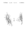
- the external acoustic meatus is generally narrow and tortuous as shown in the coronal view in FIG. 1 .
- the ear canal 10 is approximately 23-29 millimeters (mm) long from the canal aperture 17 to the tympanic membrane 18 (eardrum).
- the lateral part, a cartilaginous region 11 is relatively soft due to the underlying cartilaginous tissue.
- the cartilaginous region 11 of the ear canal 10 deforms and moves in response to the mandibular (jaw) motions, which occur during talking, yawning, eating, etc. Hair 12 is primarily present in the cartilaginous region.
- the medial part a bony region 13 proximal to the tympanic membrane, is rigid due to the underlying bony tissue.
- the skin 14 in the bony region 13 is thin (relative to the skin 16 in the cartilaginous region) and is sensitive to touch or pressure.
- a characteristic bend 15 roughly occurring at the bony-cartilaginous junction 19 separates the cartilaginous and bony regions 11 and 13 , respectively. The magnitude of this bend varies significantly among individuals.
- a cross-sectional view of the typical ear canal 10 ( FIG. 2 ) reveals generally an oval shape with a long diameter D L in the vertical axis and a short diameter D S in the horizontal axis. Canal dimensions vary significantly among individuals as shown below in the section titled Experiment-A.
- the long/short ratio (D L /D S ) ranges from 1:1 to 2:1.
- the diameter ranges from as little as 4 mm (D S in the bony region 13 in small canals) to as much as 12 mm (D L in the cartilaginous region 11 in large canals).
- Physiological debris 4 in the ear canal is primarily produced in the cartilaginous region 11 , and includes cerumen (earwax), sweat, and oils produced by the various glands underneath the skin in the lateral portion of the cartilaginous region.
- Cerumen is naturally extruded from the ear canal by the process of lateral epithelial cell migration (see, e.g., Ballachanda, The Human Ear Canal , Singular Publishing, 1950, pp. 195).
- the ear canal 10 terminates medially with the tympanic membrane 18 .
- Externally and lateral to the ear canal are the concha cavity 2 and the auricle 3 .
- Hearing loss naturally occurs beginning at higher frequencies (4000 Hz and above) and increasingly spreads to lower frequencies with age.
- CIC Completely-In-the-Canal
- CIC devices require frequent insertion and removal from the ear canal. Manufacturers often recommend daily removal for cleaning and maintenance of the CIC device (see, e.g., Users's Instructions, SENSO CIC and Mini Canal , Widex Hearing Aid Co. February 97, pp. 11, 16; and General Information for Hearing aid Users , Siemens Hearing Instruments, Inc. March 98, p. 8). Frequent removal of conventional CICs is also required for relieving the ear from the pressures of the device occluding the cartilaginous region. Furthermore, CIC hearing aid removal is also required in order to replace its battery, typically lasting from 1 to 2 weeks. The manual dexterity required to handle a CIC hearing device frequently poses a serious challenge to the many hearing impaired persons represented by the elderly. These individuals typically suffer from arthritis, tremors, or other neurologic problems that limit their ability to handle a miniature hearing aid.
- Acoustic feedback occurs when a portion of the sound output, typically from a receiver (speaker), leaks to the input of a sound system such as a microphone of a hearing aid. This leakage often causes a sustained oscillation, which is manifested by “whistling” or “squealing”. Feedback is not only annoying to hearing aid users but also interferes with their communication. Feedback is typically alleviated by occluding (sealing) the ear canal tightly, particularly at the cartilaginous region 11 , as illustrated with the CIC hearing device in FIG. 3 .
- CIC devices are custom made according to an impression taken from the ear of the individual.
- the device housing 22 (FIG. 3 ), known as a shell, is custom fabricated according to the impression, to accurately assume the shape of the individual ear canal.
- Customizing a conventional CIC is required in order to minimize feedback and to improve comfort of wear. But custom manufacturing is time consuming and results in considerable cost overhead for the manufacturer, ultimately reflected in the price of the CIC device to the consumer (user). Furthermore, impression taking is often uncomfortable for the user.
- the efficiency of a hearing device is generally inversely proportional to the distance or residual volume 25 ( FIG. 3 ) between the receiver (speaker) end 23 and the tympanic membrane 18 , the closer the receiver is to the tympanic membrane, the less air mass there is to vibrate, and thus, less energy is required.
- CIC products are typically tapered at their medial end 23 (e.g., Chasin, pp. 9-10) and relatively shallow in their placement in order to avoid substantial contact with the bony portion of the ear canal as shown in FIG. 3 .
- a shell, or main housing is typically made of rigid material such as plastic (e.g. acrylic). Typical thickness for this housing or enclosure of CIC devices is 0.5 to 0.7 mm, which adds considerable dimensions to the conventional CIC. Furthermore, conventional shells enclose the battery along with other components, which makes the overall housing large. This space inefficiency renders the device unsuitable for many individuals with small or highly contoured ear canals who would not be able to comfortably tolerate insertion and wear of a CIC device deep in the ear canal.
- a removal strand 24 ( FIG. 3 ) is generally provided with CIC devices to assist the wearer in the daily removal process. Due to the resultant discomfort and abrasion, hearing devices are frequently returned to the manufacture for improvement of the custom fit and comfort (e.g., Chasin, p. 44). “The long term effects of the hearing aid are generally known, and consist of atrophy of the skin and a gradual remodeling of the bony canal. Chronic pressure on the skin lining the ear canal causes a thinning of this layer, possibly with some loss of skin appendages” (Chasin, p. 58).
- Cerumen impaction (blockage of the ear canal by earwax) may occur when cerumen, produced in the cartilaginous region, is pushed and accumulated deeper in the bony region of ear canal by the frequent insertion of a CIC hearing device (e.g., Chasin, p. 27, pp. 56-57). Cerumen can also build up on the receiver of the hearing device causing frequent malfunction. Cerumen contamination due to frequent insertion is probably the most common factor leading to hearing aid damage and repair (see, e.g., Oliveira, et al, The Wax Problem: Two New Approaches , The Hearing Journal, Vol. 46, No. 8).
- the occlusion effect a common acoustic problem attributable to occlusion of the ear canal by the hearing device, is manifested by the perception of the user's (wearer's) own voice (“self-voice”) being loud and unnatural compared to that with an open (unoccluded) ear canal. This phenomenon is sometimes referred to as the “barrel effect”, since it resembles the experience of talking into a barrel.
- the occlusion effect which may be experienced by plugging the ears with fingers while talking, is generally related to self-voice resonating within the ear canal. For hearing aid users, the occlusion effect is inversely proportional to the residual volume 25 ( FIG.
- Cirillo in U.S. Pat. No. 4,830,139 discloses means for holding a speaker mold (16 in Cirillo's FIG. 1) in the ear canal via a sealant made of flexible gelatinous water-soluble material.
- the mold is attached to a wire (18) extending to the outside of the ear canal, and therefore, Cirillo's proposal is presumably also for hearing devices that are positioned outside the ear canal. It does not deal with devices that are completely positioned in the ear canal.
- the sealant is water-soluble, it can also be assumed to be suitable only for short-term use as it will deteriorate with moisture exposure (e.g., as will occur when the wearer is taking a shower or is caught in the rain).
- Sauer et al in U.S. Pat. No. 5,654,530 disclose an insert associated with an ITE device (Sauer's FIG. 1) or a BTE device (Sauer's FIG. 2).
- the insert is stated to be a “sealing and mounting element” made of “soft elastic material having slotted outer circumference divided into a plurality of fan-like circumferential segments”.
- the sealing element is positioned at the lateral portion of the ear canal as shown in Sauer's figures.
- the insert is for ITEs and BTEs only, not for inconspicuous hearing devices that are deeply and completely inserted in the ear canal.
- the insert as disclosed is used in the cartilaginous area, thus occluding the ear canal in the region of hair, cerumen and sweat production. Clearly, long term use (without daily removal) will interfere in the natural production of physiologic debris.
- a hearing device 10 in Garcia's FIG. 1
- the device 10 comprises hearing aid components (i.e., microphone 12, receiver 15 and battery 16, etc., as shown by Garcia) which are contained within a single “unitary” housing 20.
- the device 10 is not likely to fit deeply and comfortably in many small and contoured canals due to the space inefficiency associated with the unitary housing 20.
- the device 10 occludes the ear canal in the cartilaginous region as shown in Garcia's FIG. 2.
- Weiss et al. in U.S. Pat. Nos. 3,783,201 and 3,865,998 disclose an alternate hearing device configuration which fits partially in the ear canal (FIG. 1 in both the Weiss '201 and '998 patents) with a separate microphone 14 and receiver 18.
- the main housing, enclosing battery and amplifier, is designed to fit in the concha area outside the ear canal as shown.
- the microphone 14 is positioned in the pinna completely outside the ear canal. The device is clearly visible to the casual observer.
- Geib in U.S. Pat. No. 3,527,901 discloses a hearing device with housing made of soft resilient material, which encloses the entire body of the device. This approach eliminates conventional rigid enclosures, and is presumably more comfortable to wear. However, the unitary flexible enclosure provides no improvement in space efficiency and also poses serious concerns regarding the reliability of interconnects, and of the device in general, during frequent handling.
- the disclosed hearing device was not designed to fit entirely in the ear canal, Geib stating that “the hearing aid makes a much better fit within the concha and ear canal of the user thereby providing a more effective seal and reducing the problems of direct acoustic feedback” (col 2, lines 40-43).
- Voroba et al in U.S. Pat. No. 4,870,688 also disclose a mass-producible hearing aid, which includes a solid shell core (20 in Veroba's FIGS. 1 and 2) with a flexible covering 30 affixed to its exterior.
- the rigid core represents a unitary enclosure for all major hearing aid components, and thus, is space-inefficient for deep canal fittings.
- Hartl et al. in U.S. Pat. No. 4,639,556 disclose a hearing aid with a flexible printed circuit board attached to a face-plate.
- the flexible circuit board and major hearing aid components are also enclosed in a unitary housing (1 in Hartl's FIG. 1). Similarly, this leads to a space-inefficient design for deep canal fittings.
- the receiver portion insertable into the ear canal with the main part occupying the concha (McCarrel's FIG. 2, Geib's FIG. 10, and Adelman's FIG. 3B).
- This placement facilitates access to the device for insertion and removal.
- the aforementioned main part contains all the major components of the hearing device, including among others the battery, amplifier and microphone, except the receiver. Therefore, this main part is not sufficiently space-efficient to fit past the aperture of the ear canal for most individuals.
- Shennib et al in U.S. Pat. No. 5,701,348 disclose an articulated hearing device with flexibly connecting modules, stating that “the main module 12 includes all of the typical components found in hearing devices, except for the receiver” (col. 6, lines 64-66).
- the main module includes a battery 16, a battery compartment 15, circuit 17 (amplifier) and microphone 14. Because if its articulated design and assorted soft acoustic seal 43, the hearing device disclosed by Shennib is suitable to fit a variety of ear canals without resorting to custom manufacturing, and thus can be mass-producible as disclosed.
- a CIC configuration is disclosed (see Shennib's FIG.
- the depth of insertion is severely limited by the design of the main module 12 which contains the power source (battery) along with other major components (e.g., the microphone).
- the device substantially occludes the ear canal in the cartilaginous region, which would interfere with hair and the natural production of physiologic debris.
- the disclosed CIC configuration is designed for insertion and removal by a wearer with good dexterity (col. 11, lines 18-20). Therefore, the disclosed CIC device would be unsuitable for continuous long-term use in the ear canal, particularly for persons lacking such dexterity.
- Another objective is to provide a design for a hearing device which is mass-producible, and which requires neither custom manufacture nor the taking of individual ear canal impressions.
- a further objective of the invention is to provide a hearing device which occludingly seals the ear canal in the bony region, but not at the cartilaginous region, and thus does not interfere with hair and the natural production and elimination of physiologic debris in the ear canal.
- Yet another objective is to provide a semi-permanent hearing device which is inserted by a physician, or by other professionals under the supervision of a physician, for long-term use in the ear canal.
- Semi-permanent, or alternatively long-term use is defined herein as continuous placement and use of the hearing device within the ear canal without any removal, daily or otherwise, for at least a month.
- the invention provides a semi-permanent hearing device which is completely positioned within the ear canal of an individual for long-term use.
- the device comprises a sealing retainer substantially positioned in the bony region of the ear canal and a core assembly comprising a receiver assembly coaxially positioned within the sealing retainer.
- the core assembly extends from the sealing retainer to the cartilaginous region in a non-occluding fashion, thus minimizing interference with hair and earwax production present in the cartilaginous part of the ear canal.
- the core assembly includes a battery assembly including a battery and a thin enclosure having substantially the shape and dimensions of the battery which is encapsulated therein.
- a connector having the shape of thin ribbon film provides electrical and flexible mechanical connectivity between the receiver assembly, centrally positioned battery assembly, and microphone assembly positioned in the cartilaginous region.
- the invention is characterized by the absence of a unitary enclosure or main housing which typically encloses the battery and other components in prior art hearing device designs.
- the hearing device is mass-producible and accommodates a variety of canal shapes and sizes without need for custom manufacturing or canal impressions. This desirable objective is accomplished by virtue of the flexibility of the universal core assembly and conformity of the assorted sealing retainer.
- the hearing device of the invention is preferably inserted by a physician, or by another professional under the supervision of a physician, for placement entirely within the ear canal and exceptionally close to the eardrum.
- the space and energy efficient design allows for a comfortable continuous use within the ear canal for extended periods of time, exceeding one month, without the requirement of daily removal as with conventional CICs.
- the device is remotely switched on/off by a remote control for optionally conserving the battery energy while the device remains in the ear canal during sleep or non-use.
- the invention eliminates the need for manual insertion and removal by the wearer and is therefore particularly suited for hearing impaired persons of poor manual dexterity.
- FIG. 1 is a side view of the external ear canal, described above;
- FIG. 2 is a cross-sectional view of the ear canal at the bony-cartilaginous junction for (a) small canal, (b) average size canal and (c) large canal, showing the relative dimensions of standard button cell hearing aid batteries, sizes 10A and 312;
- FIG. 3 is a side view of the ear canal occluded by a conventional CIC hearing aid positioned therein, described above;
- FIG. 4 is a side view of the ear canal showing an embodiment of the semi-permanent canal device of the present invention positioned completely therein, in which the cartilaginous region is unoccluded and the body region is occluded with a sealing retainer;
- FIG. 5 is a detailed side view of the semi-permanent canal device of FIG. 4 , further illustrating replaceable debris guards for the microphone and receiver;
- FIGS. 6 a and 6 b are cross-sectional views of the ear canal showing the non-occlusive microphone assembly of an embodiment of the canal device of the present invention positioned in the cartilaginous region, providing substantial air-space and no contact with the walls of the ear canal ( FIG. 6 a ), and substantial air-space and minimal contact with the walls or physiologic debris of the ear canal ( FIG. 6 b );
- FIGS. 7 a and 7 b are cross-sectional views of the ear canal showing the receiver assembly and sealing retainer of an embodiment of the canal device of the invention positioned in the bony region with occlusion thereof ( FIG. 7 a ), and with venting incorporated in the sealing retainer ( FIG. 7 b );
- FIG. 8 is an electrical schematic diagram of a prototype embodiment of the canal device of the invention.
- FIG. 9 is a graph of the acoustic response of the prototype embodiment of FIG. 8 showing the acoustic effect with and without the moisture-proof debris guards placed on the microphone and the receiver of the prototype embodiment;
- FIG. 10 is a detailed exploded side view of the flexible connector, battery, microphone and receiver parts of an embodiment of the canal device of the present invention, showing the parts unassembled;
- FIG. 11 is a cross-sectional view of the ear canal showing the battery assembly of an embodiment of the canal device of the invention positioned therein, with flexible connector, battery and battery enclosure;
- FIG. 12 is a side view of the ear canal showing a programmable embodiment of the canal device of the invention positioned in the ear canal with sealing retainer extending substantially over the battery, and also illustrating a probe tube system with probe tube and external amplifier according to the invention;
- FIG. 13 is a side view of the ear canal showing an embodiment of the canal device of the invention positioned in the ear canal with a latchable magnetic switch and an external control magnet;
- FIG. 14 a is a detailed view of a moisture-proof debris guard in the form of an adhesive pad showing the adhesive layer and receiver sound port for an embodiment of the canal device of the invention
- FIG. 14 b is a perspective view of the moisture-proof adhesive pad of FIG. 14 a showing the adhesive layer and adhesive-free area
- FIG. 15 is a side view of the ear canal showing an alternate embodiment of the canal device of the invention positioned entirely in the ear canal and substantially in the bony region thereof;
- FIGS. 16 a and 16 b are perspective views of a preferred embodiment of the sealing retainer of the canal device, taken respectively from the side ( FIG. 16 a ) and from the lateral end ( FIG. 16 b ), showing a lateral cavity which partially accommodates the battery assembly indicated by the dotted circle;
- FIG. 17 is a side view of the ear canal showing the central location of the three regions representing the cartilaginous region (C), the bony-cartilaginous junction region (J) and the bony region (B).
- the present invention provides a semi-permanent hearing device which is adapted to be entirely positioned in the ear canal for long term use.
- a semi-permanent hearing device which is adapted to be entirely positioned in the ear canal for long term use.
- Hearing device 30 generally comprises a core assembly 35 and a sealing retainer 70 constructed and adapted to be positioned substantially in the bony region 13 of the ear canal.
- the core assembly 35 includes a receiver (speaker) assembly 60 , which is coaxially positioned within the sealing retainer 70 .
- the core assembly 35 extends to the cartilaginous region 11 in a non-occluding fashion, thus minimizing interference with hair and earwax production present in the cartilaginous part of the ear canal 10 .
- the core assembly 35 also includes a battery assembly 50 having a shape and dimensions substantially equivalent to those of the enclosed battery 51 , recognizing that battery assembly 50 has a slightly larger size to accommodate snug enclosure of the battery 51 therein.
- a connector 53 in the shape of thin circuit film or ribbon cable, provides electrical and mechanical connectivity between the receiver assembly 60 , the battery assembly 50 , and a microphone assembly 40 , the latter being positioned in the cartilaginous region 11 when the hearing device is fully inserted and seated in the ear canal for normal use.
- the connector 53 is enclosed within the thin enclosure 52 of the battery assembly 50 and extends to the microphone assembly 40 and receiver assembly 60 for connection thereto.
- the sealing retainer 70 is adapted to be positioned, as shown, substantially in the bony region 13 concentrically or coaxially over the receiver assembly 60 .
- the sealing retainer 70 is configured to provide the primary support for the device 30 within the ear canal 10 .
- sealing retainer 70 substantially conforms to the shape of walls 14 of the ear canal in the bony region 13 and retains the device securely within the ear canal 10 .
- the microphone assembly 40 including a microphone 43 therein, is non-occludingly positioned in the cartilaginous region 11 with little or no contact with the walls of the ear canal, thus allowing for a substantial air space 49 therebetween as shown in FIGS.
- This minimal contact of the microphone assembly 40 allows for natural production and lateral migration of cerumen (earwax) and other debris in the cartilaginous region 11 .
- the receiver assembly 60 in contrast, occludes the ear canal in the bony region 13 via the associated sealing retainer 70 , as shown in FIG. 7 .
- the microphone assembly 40 , battery assembly 50 , and receiver assembly 60 each having an individual thin encapsulation 45 ( FIGS. 6 a , 6 b ), 52 ( FIG. 11 ) and 62 ( FIGS. 7 a , 7 b ), respectively.
- the encapsulation preferably comprises a moisture-proof material or coating such as silicone, paralene or acrylic.
- the thin encapsulation may be made soft, such as soft silicone, or rigid, such as hard acrylic. Any exposed part of connector 53 extending from battery assembly 50 must be moisture-proofed in order to protect the hearing device from the damaging affects of moisture produced within or outside the ear canal.
- the connector 53 and battery 51 are encapsulated by a thin disposable enclosure 52 according to the disclosure of the '741 patent.
- the battery assembly 50 minimally occludes the ear canal and is preferably positioned substantially at or beyond the bony-cartilaginous junction 19 ( FIG. 1 ; see, also, J of FIG. 17 ).
- microphone debris guard 42 ( FIG. 5 ) and receiver debris guard 67 are placed on microphone and receiver ports 46 and 63 , respectively.
- the microphone guard 42 in the embodiments of FIGS. 4 and 5 is in the form of a replaceable cap with a cap body 48 ( FIG. 5 ) fitted over the microphone port 46 (in the direction of arrow 31 ) and guard member 47 made of a thin membrane or screen material that is substantially transparent to sound.
- receiver guard 67 FIG. 5
- receiver guard 67 may also be in the form of a replaceable cap with cap body 65 fitted over the receiver in the direction of arrow 32 with guard member 65 ′′ positioned over receiver sound port 63 .
- the microphone assembly 40 When the hearing device 30 is fully inserted in its normal position in the ear canal 10 , the microphone assembly 40 is positioned at the cartilaginous region 11 with a substantial air-space 49 all around the microphone assembly ( FIGS. 6 a , 6 b ), between the enclosure 45 of the microphone assembly and the canal skin 16 (walls). The microphone assembly 40 is positioned substantially clear from hair 12 and physiologic debris 4 produced in the cartilaginous region 11 .
- the alternate ear canal 10 ′ of FIG. 6 b is depicted as being relatively narrow, and although a substantial air-space 49 is also present, the microphone assembly 40 makes minimal contact with the wall of the canal or with physiologic debris 4 therein at the contact area 5 .
- connector 53 which is flexibly connected to battery assembly 50 in the preferred embodiment, allows microphone assembly 40 freedom to move along the cross-section of the ear canal in response to pressure from physiologic debris 4 production or canal deformations associated with jaw movements.
- the receiver assembly 60 is positioned in ear canal 10 at bony area 13 , with sealing retainer 70 in direct contact with canal skin 14 (walls), thus occluding the bony area of the canal.
- a vent 61 ( FIGS. 5 and 7 a ) is provided for pressure equalization during insertion and removal or during changes in atmosphere pressure. The vent may alternatively be provided across the sealing retainer 70 ( FIG. 7 b ). The vent 61 is also provided to minimize occlusion effects described above.
- the microphone assembly 40 in the preferred embodiment of FIGS. 4-6 comprises a microphone 43 , a control element 41 (i.e., volume trimmer as shown in FIG. 5 ) and switch assembly 44 .
- the switch assembly 44 comprises a latchable read-switch assembly (RS in FIG. 8 ), which is remotely activated by a remote magnet (e.g., 120 in FIG. 13 ) according to the disclosure in the '533 application.
- the microphone 43 comprises a microphone transducer with an integrated signal processing amplifier (for example, series FI-33XX manufactured by Knowles Electronics of Itasca, Ill.). This integration reduces the size of the microphone assembly, which further reduces occlusion effects within the ear canal at the cartilaginous region.
- the signal processing amplifier may be a separate component, as shown at 28 in the embodiment of FIG. 12 .
- FIG. 8 A schematic diagram of an electroacoustic circuit of the embodiment of FIGS. 4-7 is shown in FIG. 8 .
- the microphone M comprising a microphone transducer and signal processing amplifier integrated therein, picks up acoustic signals S M entering the ear canal and produces amplified electrical signal at terminal OUT of microphone M.
- the electrical signal is then delivered to input (IN) terminal of the receiver R via coupling capacitors C 1 and C 2 .
- the receiver R then produces amplified acoustic signal S R for delivery to the tympanic membrane 18 (FIG. 4 ).
- Volume trimmer R G connecting the output (OUT) and feedback (FB) terminals of the microphone M, is adjusted to set the gain (volume) of the electroacoustic circuit.
- Jumper J 1 (also shown in FIG. 5 ) may be removed (by cutting for example) to reduce the coupling capacitance, thus altering the frequency response of the hearing device as known to those skilled in the art of electronics.
- Other jumpers (not shown) may also be incorporated in order to increase the range of adjustable parameters of the hearing device.
- a capacitor C R is employed to stabilize the supply voltage (V+) across the supply terminals (+ and ⁇ ) of the receiver R.
- the connector 53 in the preferred embodiment shown in more detail in FIG. 10 , comprises a flexible film 54 with circuit wires 55 , 56 , 57 and 58 , which electrically interconnect the microphone 43 , receiver 64 , battery 51 , volume trimmer 41 , and other components (which are not shown, for the sake of clarity), such as switch assembly 44 (shown in FIG. 5 ) and capacitors.
- the microphone 43 (shown unassembled) is soldered to the connector 53 via solder terminals 81 on the lateral section 83 of the flexible film 54 and solder terminals 81 ′ on the microphone 43 .
- the receiver 64 is soldered to the connector 53 via solder terminals 82 on the medial section 85 of the flexible film 54 and solder terminals 82 ′ on the receiver 64 .
- Conductive pads 91 and 92 on the connector provide power connectivity from the positive 94 and negative 97 ( FIG. 11 ) terminals, respectively, of the battery 51 .
- Volume trimmer 41 is also connected to solder terminals 81 via trimmer solder terminals 41 ′.
- the lateral and medial sections 83 and 85 respectively of film 54 are flexibly bendable with respect to the main section 87 , thus allowing the connected microphone assembly 40 and receiver assembly 60 to articulate within the ear canal during insertion and removal of the hearing device.
- a crossing section 88 of the connector 53 also bends in the direction of arrow 93 (into the paper) in order to connect conductive pad 92 to the negative terminal 97 ( FIG. 11 ) of the battery.
- the flexible film 54 is provided with relief notches 84 , 86 and 89 which increase the flexibility of the sections 83 , 85 and 88 , respectively.
- the battery 51 , main section 87 , and crossing section 88 are encapsulated by thin disposable battery encapsulation 52 ( FIG.
- the main section 87 includes a vent hole 95 for allowing air circulation to battery hole 96 , typically available in air-zinc hearing aid batteries.
- the battery encapsulation 52 must allow for the necessary aeration of the battery enclosed therein.
- FIG. 11 shows a cross sectional view of the battery assembly 50 in the ear canal 10 showing main section 87 of connector 53 , battery 51 and battery encapsulation 52 .
- the crossing section 88 extending from main section 87 is also shown crossing to the negative terminal 97 of the button cell battery 51 .
- Circuit wires 55 , 56 and 57 are also shown.
- the battery encapsulation 52 is thin and substantially conforms to the shape of the battery, thus adding negligible dimensions to the enclosed battery.
- the battery enclosure should be less than 0.3 mm in thickness in order for the battery assembly to minimally occlude the ear canal and to fit comfortably in the vicinity of the bony-cartilaginous area for most individuals.
- the hearing device 100 has a microphone assembly 40 , which extends substantially laterally in the cartilaginous area 11 as shown.
- the sealing retainer 70 although remaining substantially in the bony region 13 , is concentrically positioned over both the receiver assembly 60 and the battery assembly 50 .
- the receiver assembly 60 protrudes from the sealing retainer medially towards the tympanic membrane 18 .
- the hearing device 100 is also shown as being programmable with a programming receptacle 101 for receiving programming signals from a programming connector 102 .
- the programming connector comprises programming pins 103 which are temporarily inserted into the programming receptacle 101 during the programming of the hearing device 100 .
- hearing device 100 to be electronically adjusted via an external programming device 105 (P) and its associated programming cable 106 .
- P external programming device
- Other means for remotely programming or adjusting a hearing device are well known in the field of hearing aids and include the use of sound, ultrasound, radio-frequency (RF), infra-red (IR) and electromagnetic (EM) signals.
- RF radio-frequency
- IR infra-red
- EM electromagnetic
- FIG. 12 also shows a probe tube system 110 for the measurement of sound pressure level (SPL) produced by the hearing device 100 in the ear canal.
- the probe tube system comprises a probe tube 111 , a microphone 112 and amplifier (A) 113 .
- Electrical cable 116 connects the microphone 112 to the amplifier 113 .
- the probe tube 111 is inserted in the ear canal with its tip 115 past the receiver assembly 60 near the tympanic membrane 18 . Probe tube measurements in the ear canal are employed during the fitting process for the in-situ (while in the ear canal) electroacoustic adjustment and verification of the fitted hearing device.
- Removal handle 107 may be provided for the removal of the hearing device 100 , particularly during an emergency situation, such as infection of the ear canal or irritation therein.
- the hearing device 30 comprises a latchable reed-switch assembly 44 (RS) for remotely powering the hearing device ON/OFF via an external control magnet 120 which is positioned by the wearer (user) at the vicinity of the concha 2 .
- the control magnet 120 in the preferred embodiment has two opposing polarities; a north (N) pole 121 and south (S) pole 122 , across the length of the control magnet 120 as shown.
- the flux lines 123 emanating from the north pole towards the south pole affect the lateral (nearer) lead 44 ′ of latchable reed-switch assembly 44 .
- Flux lines 123 either latch on or off the reed-switch assembly 44 according to the polarity of the control magnet 120 nearest to lead 44 ′.
- the read-switch assembly 44 comprises a latching magnet (not shown) as disclosed in greater detail in the aforementioned '533 application, and allows hearing device 30 to be turned off to conserve battery power during sleep and other non-use periods while the device remains in the ear canal for long-term use.
- the encapsulations 45 and 62 of the microphone receiver assemblies 40 and 60 are each made of thin protective material that substantially conforms to the shape of the components encapsulated therein.
- the thickness of each encapsulation is preferably less than 0.3 mm in order to minimize occlusion of the microphone assembly 40 (see FIGS. 6 a and 6 b ) in the ear canal and to maximize the relative dimension of the conforming sealing retainer 70 in the bony region 13 (see FIGS. 7 a and 7 b ). Since the semi-permanent hearing device of the invention is handled relatively infrequently, the thickness of the encapsulation can be safely made substantially thinner than conventional enclosures of CIC devices which are typically in the range of 0.5-0.7 mm.
- the debris guard 67 is made in the form of an adhesive pad.
- the receiver debris guard is composed of an acoustically-transparent material 65 with an adhesive layer 69 on its lateral surface for attachment to the medial surface 63 ′ of receiver assembly 60 .
- the receiver assembly's medial surface 63 ′ includes the receiver sound port 63 which emits receiver sound S R that passes through the debris guard 67 as illustrated by the arrow.
- the adhesive layer 69 is partially relieved from adhesive material in the adhesive-free area 65 ′ corresponding to or mating with receiver sound port 63 .
- the adhesive-free area 65 ′ is necessary since adhesives are generally not acoustically transparent, and thus will adversely alter the frequency response of the receiver 64 if applied directly over the sound port 63 .
- the adhesive pad configuration of the debris guard is equally applicable for both the microphone and receiver sound ports, as shown at 42 and 67 , respectively, in FIGS. 12-15 .
- the adhesive pad is preferably replaceable and disposable.
- the present invention shown with button cell batteries in the above embodiments, is equally suited to accommodate other battery shapes and configurations as they are likely to be available in future hearing aid applications.
- the thin enclosure of the battery assembly of the present invention regardless of the type of battery used, conforms substantially to the shape of the enclosed battery with encapsulation thickness not to exceed 0.3 mm for the preferred embodiments of the invention.
- a cylindrical battery 51 is employed with a hearing device 130 substantially positioned in the bony region 13 of the ear canal 10 .
- the microphone end 132 of the core assembly 35 extends laterally and non-occlusively in the cartilaginous region 11 .
- the receiver end 133 is coaxially positioned within sealing retainer 70 , which acoustically seals and conforms in the bony region 13 .
- a thin encapsulation 131 not exceeding 0.3 mm, protects the entire core assembly 35 , which comprises the microphone 43 , battery 51 and receiver 64 therein.
- the sealing retainer 70 shown in greater detail in FIG. 16 , comprises a soft compressible and conforming material such as polyurethane foam or like material (a polymer) or silicone or like material.
- the sealing retainer 70 must provide significant acoustic attenuation in order to seal and prevent feedback.
- a polyurethane foam sealing retainer was molded from a mixture of 1-part aqueous solution (Polymer component Type 1A, manufactured by Hamshire Chemicals, Lexington, Mass.) and 2-part prepolymer (HYPOLTM 2002 also manufactured by Hamshire Chemicals). The mixture was poured into a silicone mold (REDU-ITTM manufactured by American Dental Supply Co. of Easten, Pa.) and allowed to heat cure at approximately 195° F. for about 15 minutes prior to removing from the silicone mold at room temperature.
- REDU-ITTM manufactured by American Dental Supply Co. of Easten, Pa.
- the molded sealing retainer 70 did not include any rigid core material therein in order to maximize the fit and comfort within the bony region of the ear canal.
- the sealing retainer 70 was made oval with long diameter D L approximately 1.6 times that of the short diameter D S .
- the inferior (lower) portion 74 is relatively pointed to match the shape of typical ear canals in the bony region.
- the sealing retainer 70 is substantially hollow with air-space 72 between the body 73 of the sealing retainer and the receiver assembly 60 when inserted therein.
- the medial opening 71 of the sealing retainer is stretchable and is made smaller than the diameter of the receiver assembly 60 in order to provide a tight fit for sealing and securing the receiver assembly and the associated hearing device within the ear canal.
- cavities 75 and 76 extend medially from the lateral end of the sealing retainer 70 . These cavities, in conjunction with the internal air-space 72 , increase the compressibility and conformity of the sealing retainer so that it can be worn more comfortably in the bony region 13 which is known for being extremely sensitive to pressure. Furthermore, the cavities 75 and 76 allow for partial enclosure of the battery assembly (dotted circle) 50 therein as shown in FIG. 16 a.
- the sealing retainer 70 made of polyurethane foam material for example as described above, is compressible and subsequently expandable with time, thus allowing for a temporary compression state prior to and during insertion into the ear canal and a subsequent expansion to conform to the ear canal and seal therein.
- the sealing retainer 70 was fabricated in an assortment of four sizes (small, medium, large and extra-large) to accommodate the broadest range of ear canals among the population studied.
- the dimensions of such fabricated assortment are tabulated in Table 1 below. The dimensions were partially derived from measurements of actual ear canal dimensions obtained from cadaver impressions as explained below in the section titled Experiment-A.
- the sealing retainer may be produced in an assortment of other sizes and shapes as needed to accommodate an even wider diversity of ear canals when studied.
- the sealing retainer is preferably disposable and must be biocompatible and hypoallergenic for a safe prolonged wear in the ear canal.
- the sealing retainer may incorporate a vent 6 as shown in FIG. 7 b . This vent may created by inserting or molding a narrow-diameter silicone tube therein, for example.
- the sealing retainer may be separately inserted, without the core assembly, for a period of time sufficient to assess comfort and appropriateness of wear prior to inserting the entire hearing device semi-permanently. This may represent a “trial wear” for an individual who may be reluctant to wear or purchase the device for whatever reason.
- the semi-permanent hearing device of the present invention comprises a disposable battery, disposable battery enclosure, or alternatively a disposable battery assembly with combined battery and enclosure.
- the preferred embodiment may be that of a disposable core assembly with assorted sealing retainers as described above.
- the cross-sectional dimensions of ear canals were measured from 10 canal impressions obtained from adult cadaver ears.
- the long (vertical) and short (horizontal) diameters, D L and D S respectively, of cross sections at the center of three regions in the ear canal were measured and tabulated. These regions represent the cartilaginous (C), the bony-cartilaginous junction (J), and the bony (B) regions.
- the diameters where measured across the widest points of each cadaver impression at each region. All measurements were taken by a digital caliper (model CD-6′′CS manufactured by Mitutoyo).
- impression material used was low viscosity Hydrophilic Vinyl Polysiloxane (manufactured by Densply/Caulk) using a dispensing system (model Quixx manufactured by Caulk). Measurements are set forth in Table 2, below.
- the diameter dimensions of the ear canal vary significantly among adult individuals. In general, variations occur more so across the short (horizontal) diameters. Furthermore, the ear canal is slightly narrower (long/short ratio) in the bony region than in the other two regions. Although not apparent from the above measurements, the cartilaginous region is expandable which facilitates insertion of wider objects through it towards the deeper region, if necessary.
- a test of insertion fit of the semi-permanent canal device was performed using the battery assembly of the invention.
- the battery assembly was selected because it represents the largest of all assemblies in the hearing device according to the present invention.
- 10 actual-size ear canal models were fabricated by dip-forming clear acrylic material (Audacryl-acrylic manufactured by Esschem).
- Two battery assemblies according to the embodiment of FIGS. 10-11 were fabricated and inserted in each of the 10 ear canal models up to the bony-cartilaginous junction area.
- the first assembly comprised a size-10A battery and the second comprised size-312 battery (each is a standard button cell hearing aid battery; see FIG. 2 ).
- Each battery assembly included a thin flexible connector and was encapsulated with silicone conformal coating (model MED 10-6605 manufactured by NuSil). The thickness of the coating measured approximately 0.05 mm, thus adding negligible dimensions to the battery assembly and flexible connector thereof.
- the diameter (D) and height (H) of each assembly was measured across the widest points as tabulated in Table 3, below.
- the thickness of several shells of conventional hearing devices were also measured by comparison analysis (measuring between 0.5 mm and 0.7 mm).
- the added dimensions of (1) the shell (0.5 mm or more, adding a minimum of 1 mm to the dimensions) and (2) other enclosed components prohibit insertion of the device at the bony-cartilaginous junction (J) area for at least 5 of the above ear canals (2-R, 2-L, 3-R, 3-L and 7-L).
- J bony-cartilaginous junction
- This is further exacerbated by the fact that ear canals are often tortuously contoured, thus making it painful if not impossible to insert the conventional CIC device too deeply in seeking to gain access to the bony region of the ear canal.
- conventional CIC devices with size-312 battery larger than 10-A
- deep fitting is only likely for very large ear canals, such as 1-R and 1-L.
- the first battery assembly (size-10A) was successfully inserted up to the bony-cartilaginous junction (J) region in 9 of the 10 ear canal models, excepting 2-R which has dimensions of 4.0 ⁇ 8.9 mm (D S ⁇ D L ) as shown in FIG. 2 .
- the second battery assembly (size-312) was successfully inserted up to the bony-cartilaginous junction in 5 of the 10 ear canal models. This is particularly significant, since size-312 batteries are virtually excluded from conventional CIC devices due to their excessive size in conjunction with conventional CIC designs.
- a prototype of the semi-permanent hearing device according to the embodiment of FIGS. 4-10 was fabricated and positioned by an otolaryngologist (ear-nose-throat physician) in the left ear canal of a 55 year old male subject who suffered a moderate level of high frequency hearing loss.
- the circuit of FIG. 8 was implemented with a miniature microphone/amplifier (model FI-3342 manufactured by Knowles Electronics of Itasca, Ill.), class-D receiver (model FS3379 also manufactured by Knowles Electronics), and miniature 250K ohm volume trimmer R G (model PJ-62 manufactured by Microtronics A/S of Denmark).
- Miniature capacitors C 1 , C 2 and C R with values of 2.2 nF, 0.01 uF and 2.2 uF, respectively were employed.
- a reed switch assembly (RS) employing a miniature reed-switch (model HSR-003DT, manufactured by Hermetic Switch, Inc. of Chickasha, Okla.) and a miniature Neudymium Iron Boron (NdFeB) magnet for latching the reed-switch.
- RS reed switch assembly
- the microphone assembly comprising microphone amplifier M, reed-switch assembly RS, volume trimmer R G , and lateral section 83 of flexible connector 53 were glued together using cyanoacrylate (#20269, manufactured by Loctite Corp. of Rocky Hill, Ct.). The microphone assembly was then encapsulated by thin moisture proofing silicone material (E41 manufactured by Wacker, Werk Burghausen of Germany). The receiver assembly, comprising receiver and C R capacitor was similarly encapsulated by silicone material and was flexibly connected to the Kapton tape connector.
- the moisture-proof debris guard for the microphone and receiver ports employed Gore-TexTM material (#VE00105 manufactured by W.L. Gore & Associates of Elkton, Md.) for guard member and polypropylene plastic (#100-8932 distributed by Henry Schein/ZAHN of Esschem of Port Washington, N.Y.) for the body of the guard cap.
- Gore-TexTM material #VE00105 manufactured by W.L. Gore & Associates of Elkton, Md.
- polypropylene plastic #1100-8932 distributed by Henry Schein/ZAHN of Esschem of Port Washington, N.Y.
- the guard member material was approximately 0.2 mm in thickness.
- a large-sized sealing retainer was fabricated using the above mentioned polymer foam material and fabrication process.
- the device excluding the retainer seal, weighed 0.73 grams, including the 10A battery which weighed 0.29 grams alone.
- the subject was provided with a control magnet, in the shape of a bar, for remotely switching the device on or off as desired.
- the moisture-proofing provided by the debris guards and enclosures according to the invention can even afford the wearer the opportunity to engage in normal swimming without fear of damage to or loss of fidelity of the hearing device. It would not be recommended that the wearer engage in diving or prolonged underwater swimming, however.
- the sealing retainer provides acoustic sealing of the bony region to prevent feedback, and the lateral extension of the core assembly avoids substantial interference with hair and production of cerumen and debris in the cartilaginous region.
Abstract
Description
| TABLE 1 | ||
| Size | Short Diameter (DL) in mm | Large Diameter (DL) in mm |
| Small | 4.5 | 7.25 |
| Medium | 5.75 | 9.35 |
| Large | 7.3 | 12 |
| Ex-Large | 9.0 | 15 |
| TABLE 2 | ||||
| C-Region | ||||
| Diameters | ||||
| in mm | J-Region Diameters | B-Region Diameters | ||
| Sample | Short | Long | in mm | in mm |
| # | (DS) | (DL) | Short (DS) | Long (DL) | Short (DS) | Long (DL) |
| 1-R | 7.8 | 10.3 | 8.1 | 10.7 | 8.0 | 10.5 |
| 1-L | 7.8 | 11.9 | 8.3 | 12.2 | 8.1 | 11.2 |
| 2-R | 3.8 | 8.9 | 4.0 | 8.9 | 4.2 | 8.9 |
| 2-L | 5.3 | 8.1 | 4.4 | 8.8 | 4.3 | 8.6 |
| 3-R | 5.5 | 6.3 | 4.7 | 6.7 | 5.0 | 7.7 |
| 3-L | 4.9 | 6.5 | 4.9 | 6.5 | 4.9 | 7.3 |
| 4-R | 6.9 | 9.2 | 6.5 | 9.6 | 6.7 | 10.4 |
| 5-R | 6.9 | 9.2 | 7.2 | 8.4 | 7.5 | 9.5 |
| 5-L | 6.8 | 8.2 | 7.6 | 9.4 | 7.5 | 8.7 |
| 7-L | 6.3 | 7.0 | 5.1 | 6.7 | 4.9 | 6.7 |
| Average | 6.2 | 8.6 | 6.1 | 8.8 | 6.1 | 9.0 |
Results and Conclusion
| TABLE 3 | ||
| Battery | Height (H) | Diameter (D) |
| Assembly | in mm | in |
| 10A Bat. | 4.4 (H) | 6.5 (D) |
| 312 Bat. | 4.5 (H) | 8.0 (D) |
Results and Conclusion
Claims (49)
Priority Applications (14)
| Application Number | Priority Date | Filing Date | Title |
|---|---|---|---|
| US09/199,669 US6940988B1 (en) | 1998-11-25 | 1998-11-25 | Semi-permanent canal hearing device |
| PCT/US1999/026021 WO2000032009A2 (en) | 1998-11-25 | 1999-11-24 | Semi-permanent canal hearing device |
| AU19083/00A AU773468B2 (en) | 1998-11-25 | 1999-11-24 | Semi-permanent canal hearing device |
| JP2000584719A JP4384360B2 (en) | 1998-11-25 | 1999-11-24 | Canal type hearing device that can be worn semi-permanently |
| EP99962690A EP1151636B1 (en) | 1998-11-25 | 1999-11-24 | Semi-permanent canal hearing device |
| DK99962690.6T DK1151636T3 (en) | 1998-11-25 | 1999-11-24 | Semi-permanent in-ear hearing aid |
| CA002352145A CA2352145A1 (en) | 1998-11-25 | 1999-11-24 | Semi-permanent canal hearing device |
| US10/693,628 US7310426B2 (en) | 1998-11-25 | 2003-10-25 | Inconspicuous semi-permanent hearing device |
| US11/115,907 US7424124B2 (en) | 1998-11-25 | 2005-04-26 | Semi-permanent canal hearing device |
| US11/238,154 US7664282B2 (en) | 1998-11-25 | 2005-09-27 | Sealing retainer for extended wear hearing devices |
| US11/452,610 US7580537B2 (en) | 1998-11-25 | 2006-06-13 | Sealing retainer for extended wear hearing devices |
| US11/453,279 US20060291683A1 (en) | 1998-11-25 | 2006-06-13 | Sealing retainer for extended wear hearing devices |
| US12/032,421 US8538055B2 (en) | 1998-11-25 | 2008-02-15 | Semi-permanent canal hearing device and insertion method |
| US12/646,740 US8503707B2 (en) | 1998-11-25 | 2009-12-23 | Sealing retainer for extended wear hearing devices |
Applications Claiming Priority (1)
| Application Number | Priority Date | Filing Date | Title |
|---|---|---|---|
| US09/199,669 US6940988B1 (en) | 1998-11-25 | 1998-11-25 | Semi-permanent canal hearing device |
Related Child Applications (3)
| Application Number | Title | Priority Date | Filing Date |
|---|---|---|---|
| US09/327,717 Continuation US6473513B1 (en) | 1998-11-25 | 1999-06-08 | Extended wear canal hearing device |
| US10/693,628 Continuation US7310426B2 (en) | 1998-11-25 | 2003-10-25 | Inconspicuous semi-permanent hearing device |
| US11/115,907 Continuation US7424124B2 (en) | 1998-11-25 | 2005-04-26 | Semi-permanent canal hearing device |
Publications (1)
| Publication Number | Publication Date |
|---|---|
| US6940988B1 true US6940988B1 (en) | 2005-09-06 |
Family
ID=22738522
Family Applications (4)
| Application Number | Title | Priority Date | Filing Date |
|---|---|---|---|
| US09/199,669 Expired - Fee Related US6940988B1 (en) | 1998-11-25 | 1998-11-25 | Semi-permanent canal hearing device |
| US10/693,628 Expired - Fee Related US7310426B2 (en) | 1998-11-25 | 2003-10-25 | Inconspicuous semi-permanent hearing device |
| US11/115,907 Expired - Fee Related US7424124B2 (en) | 1998-11-25 | 2005-04-26 | Semi-permanent canal hearing device |
| US12/032,421 Expired - Fee Related US8538055B2 (en) | 1998-11-25 | 2008-02-15 | Semi-permanent canal hearing device and insertion method |
Family Applications After (3)
| Application Number | Title | Priority Date | Filing Date |
|---|---|---|---|
| US10/693,628 Expired - Fee Related US7310426B2 (en) | 1998-11-25 | 2003-10-25 | Inconspicuous semi-permanent hearing device |
| US11/115,907 Expired - Fee Related US7424124B2 (en) | 1998-11-25 | 2005-04-26 | Semi-permanent canal hearing device |
| US12/032,421 Expired - Fee Related US8538055B2 (en) | 1998-11-25 | 2008-02-15 | Semi-permanent canal hearing device and insertion method |
Country Status (7)
| Country | Link |
|---|---|
| US (4) | US6940988B1 (en) |
| EP (1) | EP1151636B1 (en) |
| JP (1) | JP4384360B2 (en) |
| AU (1) | AU773468B2 (en) |
| CA (1) | CA2352145A1 (en) |
| DK (1) | DK1151636T3 (en) |
| WO (1) | WO2000032009A2 (en) |
Cited By (100)
| Publication number | Priority date | Publication date | Assignee | Title |
|---|---|---|---|---|
| US20040240695A1 (en) * | 1996-03-14 | 2004-12-02 | Sarnoff Corporation | Hearing aid |
| US20040247149A1 (en) * | 2001-10-12 | 2004-12-09 | Per Kokholm Sorensen | Hearing aid, headset or similar device for delivering a sound signal at the vicinity of the tympanic membrane |
| US20040247147A1 (en) * | 2001-12-07 | 2004-12-09 | Bordewijk Lourens George | Hearing aid assembly |
| US20050190938A1 (en) * | 2004-02-05 | 2005-09-01 | Insound Medical, Inc. | Extended wear canal device with common microphone-battery air cavity |
| US20050286731A1 (en) * | 1998-11-25 | 2005-12-29 | Adnan Shennib | Inconspicuous semi-permanent hearing device |
| US20060050914A1 (en) * | 1998-11-25 | 2006-03-09 | Insound Medical, Inc. | Sealing retainer for extended wear hearing devices |
| US20060210104A1 (en) * | 1998-10-28 | 2006-09-21 | Insound Medical, Inc. | Remote magnetic activation of hearing devices |
| US20060291683A1 (en) * | 1998-11-25 | 2006-12-28 | Insound Medical, Inc. | Sealing retainer for extended wear hearing devices |
| US20060291682A1 (en) * | 1998-11-25 | 2006-12-28 | Insound Medical, Inc. | Sealing retainer for extended wear hearing devices |
| US20070009128A1 (en) * | 2000-03-13 | 2007-01-11 | Samoff Corporation | Flexible hearing aid tip with an integral receiver |
| US20070036379A1 (en) * | 2005-08-12 | 2007-02-15 | Insound Medical, Inc. | Flexible joint for extended wear hearing device |
| US20070177749A1 (en) * | 2006-01-30 | 2007-08-02 | Sjursen Walter P | Hearing aid circuit with integrated switch and battery |
| US20070189563A1 (en) * | 2006-01-30 | 2007-08-16 | Sjursen Walter P | Hearing aid with tuned microphone cavity |
| US20080056526A1 (en) * | 2006-09-01 | 2008-03-06 | Etymotic Research, Inc. | Antenna For Miniature Wireless Devices And Improved Wireless Earphones Supported Entirely By The Ear Canal |
| US20080187159A1 (en) * | 2006-10-23 | 2008-08-07 | Klipsch, Llc | Ear tip |
| US20080213664A1 (en) * | 2007-03-02 | 2008-09-04 | Front Edge Technology, Inc. | Thin film battery and manufacturing method |
| US20080240476A1 (en) * | 2007-03-30 | 2008-10-02 | Siemens Audiologische Technik Gmbh | In situ measurement |
| US20080247580A1 (en) * | 2004-06-24 | 2008-10-09 | Soon-Suck Jang | Hearing Aid Using Printed Circuit Board |
| US20090010462A1 (en) * | 2007-07-02 | 2009-01-08 | Front Edge Technology, Inc. | Compact rechargeable thin film battery system for hearing aid |
| US20090057136A1 (en) * | 2007-09-04 | 2009-03-05 | Front Edge Technology, Inc. | Manufacturing method for thin film battery |
| US20090074220A1 (en) * | 2007-08-14 | 2009-03-19 | Insound Medical, Inc. | Combined microphone and receiver assembly for extended wear canal hearing devices |
| US20090154748A1 (en) * | 2007-06-20 | 2009-06-18 | Baker Lawrence K | Cartilage displacing bead, ridge, or key projection |
| US20090208671A1 (en) * | 2008-02-18 | 2009-08-20 | Front Edge Technology, Inc. | Thin film battery fabrication using laser shaping |
| USD611929S1 (en) | 2008-05-29 | 2010-03-16 | Klipsch, Llc | Headphone ear tips |
| US20100069705A1 (en) * | 2008-09-17 | 2010-03-18 | Schumaier Daniel R | Hearing assistance device having reduced mechanical feedback |
| US20100067725A1 (en) * | 2008-09-17 | 2010-03-18 | Schumaier Daniel R | Connector for hearing assistance device having reduced mechanical feedback |
| US20100142739A1 (en) * | 2008-12-04 | 2010-06-10 | Schindler Robert A | Insertion Device for Deep-in-the-Canal Hearing Devices |
| US20100239112A1 (en) * | 2009-03-20 | 2010-09-23 | Insound Medical Inc. | Tool for insertion and removal of in-canal hearing devices |
| US20100322452A1 (en) * | 2004-02-05 | 2010-12-23 | Insound Medical, Inc. | Contamination resistant ports for hearing devices |
| US7862627B2 (en) | 2007-04-27 | 2011-01-04 | Front Edge Technology, Inc. | Thin film battery substrate cutting and fabrication process |
| US20110058697A1 (en) * | 2009-09-10 | 2011-03-10 | iHear Medical, Inc. | Canal Hearing Device with Disposable Battery Module |
| DE102010021473A1 (en) | 2010-05-25 | 2012-02-16 | Siemens Medical Instruments Pte. Ltd. | Hearing device for wearing in the ear, comprises a housing, where a foamed silicone material is arranged on the outside of the housing, to reduce nerve irritation when wearing the hearing device in the ear |
| US8340335B1 (en) | 2009-08-18 | 2012-12-25 | iHear Medical, Inc. | Hearing device with semipermanent canal receiver module |
| US20130051590A1 (en) * | 2011-08-31 | 2013-02-28 | Patrick Slater | Hearing Enhancement and Protective Device |
| WO2013077932A1 (en) | 2011-11-23 | 2013-05-30 | Ag Phonak | Cic hearing device |
| US8475955B2 (en) | 2005-03-25 | 2013-07-02 | Front Edge Technology, Inc. | Thin film battery with electrical connector connecting battery cells |
| DE102012201216A1 (en) * | 2012-01-27 | 2013-08-01 | Siemens Medical Instruments Pte. Ltd. | Ear canal insert for detachable connection with hearing aid, has outer dome made of foam material which is softer than material of connecting piece, and is permanently connected with connecting piece |
| US8502494B2 (en) | 2009-08-28 | 2013-08-06 | Front Edge Technology, Inc. | Battery charging apparatus and method |
| US8679674B2 (en) | 2005-03-25 | 2014-03-25 | Front Edge Technology, Inc. | Battery with protective packaging |
| US8682016B2 (en) | 2011-11-23 | 2014-03-25 | Insound Medical, Inc. | Canal hearing devices and batteries for use with same |
| US8693719B2 (en) | 2010-10-08 | 2014-04-08 | Starkey Laboratories, Inc. | Adjustment and cleaning tool for a hearing assistance device |
| US8753724B2 (en) | 2012-09-26 | 2014-06-17 | Front Edge Technology Inc. | Plasma deposition on a partially formed battery through a mesh screen |
| US8761423B2 (en) | 2011-11-23 | 2014-06-24 | Insound Medical, Inc. | Canal hearing devices and batteries for use with same |
| US8798301B2 (en) | 2012-05-01 | 2014-08-05 | iHear Medical, Inc. | Tool for removal of canal hearing device from ear canal |
| US20140270293A1 (en) * | 2011-12-09 | 2014-09-18 | Sophono,Inc. | Systems, Devices, Components and Methods for Providing Acoustic Isolation Between Microphones and Transducers in Bone Conduction Magnetic Hearing Aids |
| US8855345B2 (en) | 2012-03-19 | 2014-10-07 | iHear Medical, Inc. | Battery module for perpendicular docking into a canal hearing device |
| US8867768B2 (en) | 2012-11-30 | 2014-10-21 | iHear Medical, Inc. | Earpiece assembly with foil clip |
| US8864954B2 (en) | 2011-12-23 | 2014-10-21 | Front Edge Technology Inc. | Sputtering lithium-containing material with multiple targets |
| US8865340B2 (en) | 2011-10-20 | 2014-10-21 | Front Edge Technology Inc. | Thin film battery packaging formed by localized heating |
| US9002046B2 (en) | 2012-06-29 | 2015-04-07 | iHear Medical, Inc. | Method and system for transcutaneous proximity wireless control of a canal hearing device |
| US9031247B2 (en) | 2013-07-16 | 2015-05-12 | iHear Medical, Inc. | Hearing aid fitting systems and methods using sound segments representing relevant soundscape |
| US9060233B2 (en) | 2013-03-06 | 2015-06-16 | iHear Medical, Inc. | Rechargeable canal hearing device and systems |
| US9078075B2 (en) | 2012-11-30 | 2015-07-07 | iHear Medical, Inc. | Tool for insertion of canal hearing device into the ear canal |
| US9077000B2 (en) | 2012-03-29 | 2015-07-07 | Front Edge Technology, Inc. | Thin film battery and localized heat treatment |
| US9088852B2 (en) | 2013-03-06 | 2015-07-21 | iHear Medical, Inc. | Disengagement tool for a modular canal hearing device and systems including same |
| US9088846B2 (en) | 2013-08-14 | 2015-07-21 | Klipsch Group, Inc. | Oval variable wall earbud |
| US9107016B2 (en) | 2013-07-16 | 2015-08-11 | iHear Medical, Inc. | Interactive hearing aid fitting system and methods |
| US20150271609A1 (en) * | 2014-03-18 | 2015-09-24 | Earlens Corporation | High Fidelity and Reduced Feedback Contact Hearing Apparatus and Methods |
| US9185504B2 (en) | 2012-11-30 | 2015-11-10 | iHear Medical, Inc. | Dynamic pressure vent for canal hearing devices |
| US9257695B2 (en) | 2012-03-29 | 2016-02-09 | Front Edge Technology, Inc. | Localized heat treatment of battery component films |
| US9326706B2 (en) | 2013-07-16 | 2016-05-03 | iHear Medical, Inc. | Hearing profile test system and method |
| US9356320B2 (en) | 2012-10-15 | 2016-05-31 | Front Edge Technology Inc. | Lithium battery having low leakage anode |
| US9369792B2 (en) | 2013-08-14 | 2016-06-14 | Klipsch Group, Inc. | Round variable wall earbud |
| US9439008B2 (en) | 2013-07-16 | 2016-09-06 | iHear Medical, Inc. | Online hearing aid fitting system and methods for non-expert user |
| US9584895B2 (en) | 2013-08-14 | 2017-02-28 | Klipsch Group, Inc. | Teardrop variable wall earbud |
| US9769577B2 (en) | 2014-08-22 | 2017-09-19 | iHear Medical, Inc. | Hearing device and methods for wireless remote control of an appliance |
| US9788126B2 (en) | 2014-09-15 | 2017-10-10 | iHear Medical, Inc. | Canal hearing device with elongate frequency shaping sound channel |
| US9805590B2 (en) | 2014-08-15 | 2017-10-31 | iHear Medical, Inc. | Hearing device and methods for wireless remote control of an appliance |
| US9807524B2 (en) | 2014-08-30 | 2017-10-31 | iHear Medical, Inc. | Trenched sealing retainer for canal hearing device |
| US9887429B2 (en) | 2011-12-21 | 2018-02-06 | Front Edge Technology Inc. | Laminated lithium battery |
| US9905895B2 (en) | 2012-09-25 | 2018-02-27 | Front Edge Technology, Inc. | Pulsed mode apparatus with mismatched battery |
| US9924276B2 (en) | 2014-11-26 | 2018-03-20 | Earlens Corporation | Adjustable venting for hearing instruments |
| US9930458B2 (en) | 2014-07-14 | 2018-03-27 | Earlens Corporation | Sliding bias and peak limiting for optical hearing devices |
| US9949035B2 (en) | 2008-09-22 | 2018-04-17 | Earlens Corporation | Transducer devices and methods for hearing |
| US9949039B2 (en) | 2005-05-03 | 2018-04-17 | Earlens Corporation | Hearing system having improved high frequency response |
| US9961454B2 (en) | 2008-06-17 | 2018-05-01 | Earlens Corporation | Optical electro-mechanical hearing devices with separate power and signal components |
| US10008739B2 (en) | 2015-02-23 | 2018-06-26 | Front Edge Technology, Inc. | Solid-state lithium battery with electrolyte |
| US10045128B2 (en) | 2015-01-07 | 2018-08-07 | iHear Medical, Inc. | Hearing device test system for non-expert user at home and non-clinical settings |
| US10085678B2 (en) | 2014-12-16 | 2018-10-02 | iHear Medical, Inc. | System and method for determining WHO grading of hearing impairment |
| US10097933B2 (en) | 2014-10-06 | 2018-10-09 | iHear Medical, Inc. | Subscription-controlled charging of a hearing device |
| US10154352B2 (en) | 2007-10-12 | 2018-12-11 | Earlens Corporation | Multifunction system and method for integrated hearing and communication with noise cancellation and feedback management |
| US10178483B2 (en) | 2015-12-30 | 2019-01-08 | Earlens Corporation | Light based hearing systems, apparatus, and methods |
| US10284964B2 (en) | 2010-12-20 | 2019-05-07 | Earlens Corporation | Anatomically customized ear canal hearing apparatus |
| US10292601B2 (en) | 2015-10-02 | 2019-05-21 | Earlens Corporation | Wearable customized ear canal apparatus |
| US10341790B2 (en) | 2015-12-04 | 2019-07-02 | iHear Medical, Inc. | Self-fitting of a hearing device |
| CN110136560A (en) * | 2019-05-31 | 2019-08-16 | 山东交通学院 | The bionical bat ear loudspeaker model functional device of slope-intercept form and experimental method |
| US10412511B2 (en) | 2015-05-29 | 2019-09-10 | Sris Tech Limited | Hearing aid |
| US10489833B2 (en) | 2015-05-29 | 2019-11-26 | iHear Medical, Inc. | Remote verification of hearing device for e-commerce transaction |
| US10492010B2 (en) | 2015-12-30 | 2019-11-26 | Earlens Corporations | Damping in contact hearing systems |
| US11102594B2 (en) | 2016-09-09 | 2021-08-24 | Earlens Corporation | Contact hearing systems, apparatus and methods |
| US11115519B2 (en) | 2014-11-11 | 2021-09-07 | K/S Himpp | Subscription-based wireless service for a hearing device |
| US11166114B2 (en) | 2016-11-15 | 2021-11-02 | Earlens Corporation | Impression procedure |
| US11212626B2 (en) | 2018-04-09 | 2021-12-28 | Earlens Corporation | Dynamic filter |
| US11331008B2 (en) | 2014-09-08 | 2022-05-17 | K/S Himpp | Hearing test system for non-expert user with built-in calibration and method |
| US11336982B1 (en) * | 2020-12-26 | 2022-05-17 | Sonova Ag | Hearing device seal modules, modular hearing devices including the same and associated methods |
| US11350226B2 (en) | 2015-12-30 | 2022-05-31 | Earlens Corporation | Charging protocol for rechargeable hearing systems |
| US20220303663A1 (en) * | 2019-01-05 | 2022-09-22 | Shenzhen Shokz Co., Ltd. | Loudspeaker apparatus |
| US11516603B2 (en) | 2018-03-07 | 2022-11-29 | Earlens Corporation | Contact hearing device and retention structure materials |
| US11678126B1 (en) | 2021-12-09 | 2023-06-13 | Sonova Ag | Hearing device seal modules, modular hearing devices including the same and associated methods |
| EP3668119B1 (en) | 2018-12-13 | 2023-06-28 | Sivantos Pte. Ltd. | Hearing aid and method of manufacturing a hearing aid |
Families Citing this family (49)
| Publication number | Priority date | Publication date | Assignee | Title |
|---|---|---|---|---|
| US6473513B1 (en) * | 1999-06-08 | 2002-10-29 | Insonus Medical, Inc. | Extended wear canal hearing device |
| US6724902B1 (en) | 1999-04-29 | 2004-04-20 | Insound Medical, Inc. | Canal hearing device with tubular insert |
| WO2002005590A1 (en) * | 2000-06-30 | 2002-01-17 | Cochlear Limited | Cochlear implant |
| CA2709385C (en) | 2001-11-08 | 2011-07-12 | Phonak Ag | Hearing device and set of such devices |
| EP1535489A4 (en) * | 2002-07-18 | 2007-01-24 | Insound Medical Inc | Canal hearing device with tubular insert |
| JP2007522774A (en) * | 2004-02-13 | 2007-08-09 | インサウンド メディカル, インコーポレイテッド | Perforated cap for hearing aid |
| US7477756B2 (en) * | 2006-03-02 | 2009-01-13 | Knowles Electronics, Llc | Isolating deep canal fitting earphone |
| US8096383B2 (en) * | 2006-03-21 | 2012-01-17 | Siemens Hearing Instruments Inc. | Tapered vent for a hearing instrument |
| US8027638B2 (en) * | 2006-03-29 | 2011-09-27 | Micro Ear Technology, Inc. | Wireless communication system using custom earmold |
| WO2007140403A2 (en) * | 2006-05-30 | 2007-12-06 | Knowles Electronics, Llc. | Personal listening device |
| WO2007147415A1 (en) | 2006-06-23 | 2007-12-27 | Gn Resound A/S | A hearing aid with a removably connected elongate member |
| US8374367B2 (en) | 2006-06-23 | 2013-02-12 | Gn Resound A/S | Hearing aid with a flexible elongated member |
| US8111839B2 (en) * | 2007-04-09 | 2012-02-07 | Personics Holdings Inc. | Always on headwear recording system |
| US8199950B2 (en) * | 2007-10-22 | 2012-06-12 | Sony Ericsson Mobile Communications Ab | Earphone and a method for providing an improved sound experience |
| DE102007052648A1 (en) * | 2007-11-05 | 2009-05-07 | Siemens Medical Instruments Pte. Ltd. | Hearing aid, in particular BTE hearing aid |
| DE202007016881U1 (en) * | 2007-12-03 | 2009-04-09 | Sennheiser Electronic Gmbh & Co. Kg | receiver |
| US20090182399A1 (en) * | 2008-01-11 | 2009-07-16 | Diana Sylvestre | Auricular thermoregulation system for appetite suppression |
| EP2443842B1 (en) * | 2009-06-16 | 2017-12-20 | Sivantos Pte. Ltd. | Hearing aid with a replaceable insertion cap |
| EP3355594B1 (en) | 2009-07-22 | 2022-10-05 | Eargo, Inc. | Open ear canal hearing aid |
| US10097936B2 (en) | 2009-07-22 | 2018-10-09 | Eargo, Inc. | Adjustable securing mechanism |
| US10334370B2 (en) | 2009-07-25 | 2019-06-25 | Eargo, Inc. | Apparatus, system and method for reducing acoustic feedback interference signals |
| US9826322B2 (en) | 2009-07-22 | 2017-11-21 | Eargo, Inc. | Adjustable securing mechanism |
| US10284977B2 (en) | 2009-07-25 | 2019-05-07 | Eargo, Inc. | Adjustable securing mechanism |
| US8422719B2 (en) * | 2009-10-05 | 2013-04-16 | Sonomax Technologies Inc. | Miniaturized receiver assembly for in-ear noise-isolating earphones |
| KR101612851B1 (en) * | 2010-02-01 | 2016-04-18 | 삼성전자주식회사 | Small hearing aid |
| CN102271304B (en) * | 2010-07-13 | 2014-05-28 | 江苏贝泰福医疗科技有限公司 | General flexible in-ear hearing aid |
| US8885859B2 (en) * | 2010-07-16 | 2014-11-11 | Sonion Nederland Bv | Semi-permanent hearing aid |
| EP2601795B1 (en) * | 2010-08-03 | 2019-10-09 | Sonova AG | Receiver system for a hearing instrument |
| DE102011078675B4 (en) * | 2011-07-05 | 2014-01-02 | Siemens Medical Instruments Pte. Ltd. | Impression structure for a hearing device |
| US9313588B2 (en) * | 2011-07-05 | 2016-04-12 | Sivantos Pte. Ltd. | Molding structure for a hearing apparatus, hearing apparatus, and method of producing the molding structure |
| DE102011083209B3 (en) * | 2011-09-22 | 2013-01-17 | Siemens Medical Instruments Pte. Ltd. | IDO hearing instrument with programming socket |
| EP2595413B1 (en) * | 2011-11-17 | 2015-07-01 | Oticon A/S | Hearing aid fixture |
| US9408004B2 (en) | 2012-05-07 | 2016-08-02 | Starkey Laboratories, Inc. | Flex connector for a hearing assistance device |
| JP6025244B2 (en) * | 2012-06-22 | 2016-11-16 | フォスター電機株式会社 | Earpad and earphone using the earpad |
| WO2014044292A1 (en) | 2012-09-18 | 2014-03-27 | Phonak Ag | Method for charging a nimh battery, a battery charger and a system comprising a battery charger and a hearing device |
| EP3008922A1 (en) | 2013-06-13 | 2016-04-20 | Sonova AG | A rechargable hearing device, a battery charger for charging such a hearing device, and a method of charging such a hearing device |
| US20160165367A1 (en) | 2013-07-22 | 2016-06-09 | Sonova Ag | A rechargeable hearing device and a battery charger for charging the hearing device |
| WO2015039707A1 (en) | 2013-09-23 | 2015-03-26 | Phonak Ag | A rechargable hearing device, a hearing device charging system and a method for charging a hearing device |
| EP2930944A1 (en) * | 2014-04-07 | 2015-10-14 | Oticon A/s | Hearing aid comprising a flexible connection member |
| US10264370B2 (en) * | 2015-04-20 | 2019-04-16 | Oticon A/S | Hearing device configured to be placed in the ear canal of a user |
| EP3104626A1 (en) * | 2015-06-11 | 2016-12-14 | Sonova AG | Hearing aid having a magnetic switch integrated into a microphone |
| EP3113520A1 (en) * | 2015-06-30 | 2017-01-04 | Oticon A/s | Insert member for a hearing device |
| US10242657B2 (en) * | 2016-05-09 | 2019-03-26 | Snorehammer, Inc. | Snoring active noise-cancellation, masking, and suppression |
| EP4061015A3 (en) * | 2016-07-12 | 2023-02-22 | Oticon A/s | Hearing aid |
| US11388501B2 (en) | 2016-09-01 | 2022-07-12 | Zoku Limited | Earpiece with actuator |
| GB2553518B (en) * | 2016-09-01 | 2022-03-09 | Third Skin Ltd | An earpiece |
| RU192488U1 (en) * | 2017-12-20 | 2019-09-19 | Михаил Викторович Кучеренко | IN-CHANNEL HEADPHONE |
| EP3570561A1 (en) * | 2018-05-17 | 2019-11-20 | Oticon A/s | Wax filter for a speaker of hearing aid |
| EP4061013A1 (en) * | 2021-03-19 | 2022-09-21 | Xiamen Retone Hearing Technology Co., Ltd. | Completely-in-canal hearing aid |
Citations (54)
| Publication number | Priority date | Publication date | Assignee | Title |
|---|---|---|---|---|
| US3061689A (en) | 1957-05-27 | 1962-10-30 | Beltone Hearing Aid Company | Hearing aid |
| USRE26258E (en) | 1964-04-02 | 1967-08-29 | In-the-ear hearing aid | |
| US3414685A (en) | 1965-09-23 | 1968-12-03 | Dahlberg Electronics | In-the-ear hearing aid |
| US3527901A (en) | 1967-03-28 | 1970-09-08 | Dahlberg Electronics | Hearing aid having resilient housing |
| US3594514A (en) | 1970-01-02 | 1971-07-20 | Medtronic Inc | Hearing aid with piezoelectric ceramic element |
| US3764748A (en) | 1972-05-19 | 1973-10-09 | J Branch | Implanted hearing aids |
| US3783201A (en) | 1970-12-02 | 1974-01-01 | Beltone Electronics Corp | Miniature hearing aid structure |
| US3865998A (en) | 1970-12-02 | 1975-02-11 | Beltone Electronics Corp | Ear seal |
| US3870832A (en) | 1972-07-18 | 1975-03-11 | John M Fredrickson | Implantable electromagnetic hearing aid |
| US3882285A (en) | 1973-10-09 | 1975-05-06 | Vicon Instr Company | Implantable hearing aid and method of improving hearing |
| US4539440A (en) * | 1983-05-16 | 1985-09-03 | Michael Sciarra | In-canal hearing aid |
| US4606329A (en) | 1985-05-22 | 1986-08-19 | Xomed, Inc. | Implantable electromagnetic middle-ear bone-conduction hearing aid device |
| US4607720A (en) | 1984-08-06 | 1986-08-26 | Viennatone Gesellschaft M.B.H. | Hearing aid |
| US4628907A (en) | 1984-03-22 | 1986-12-16 | Epley John M | Direct contact hearing aid apparatus |
| US4639556A (en) | 1983-10-05 | 1987-01-27 | Siemens Aktiengesellschaft | Hearing aid with a flexible printed circuit board |
| US4680799A (en) | 1983-06-27 | 1987-07-14 | Siemens Aktiengesellschaft | Hearing aid |
| US4756312A (en) | 1984-03-22 | 1988-07-12 | Advanced Hearing Technology, Inc. | Magnetic attachment device for insertion and removal of hearing aid |
| US4776322A (en) | 1985-05-22 | 1988-10-11 | Xomed, Inc. | Implantable electromagnetic middle-ear bone-conduction hearing aid device |
| US4817607A (en) | 1986-03-07 | 1989-04-04 | Richards Medical Company | Magnetic ossicular replacement prosthesis |
| US4830139A (en) | 1986-08-04 | 1989-05-16 | Cirillo Evelyn J | Hearing aid holding means and method of using same |
| US4840178A (en) | 1986-03-07 | 1989-06-20 | Richards Metal Company | Magnet for installation in the middle ear |
| US4870688A (en) | 1986-05-27 | 1989-09-26 | Barry Voroba | Mass production auditory canal hearing aid |
| US4880076A (en) | 1986-12-05 | 1989-11-14 | Minnesota Mining And Manufacturing Company | Hearing aid ear piece having disposable compressible polymeric foam sleeve |
| US4937876A (en) | 1988-09-26 | 1990-06-26 | U.S. Philips Corporation | In-the-ear hearing aid |
| US4957478A (en) | 1988-10-17 | 1990-09-18 | Maniglia Anthony J | Partially implantable hearing aid device |
| US5002151A (en) | 1986-12-05 | 1991-03-26 | Minnesota Mining And Manufacturing Company | Ear piece having disposable, compressible polymeric foam sleeve |
| US5015225A (en) | 1985-05-22 | 1991-05-14 | Xomed, Inc. | Implantable electromagnetic middle-ear bone-conduction hearing aid device |
| US5015224A (en) | 1988-10-17 | 1991-05-14 | Maniglia Anthony J | Partially implantable hearing aid device |
| US5163957A (en) | 1991-09-10 | 1992-11-17 | Smith & Nephew Richards, Inc. | Ossicular prosthesis for mounting magnet |
| US5220918A (en) | 1988-11-16 | 1993-06-22 | Smith & Nephew Richards, Inc. | Trans-tympanic connector for magnetic induction hearing aid |
| US5259032A (en) | 1990-11-07 | 1993-11-02 | Resound Corporation | contact transducer assembly for hearing devices |
| US5282858A (en) | 1991-06-17 | 1994-02-01 | American Cyanamid Company | Hermetically sealed implantable transducer |
| US5338287A (en) | 1991-12-23 | 1994-08-16 | Miller Gale W | Electromagnetic induction hearing aid device |
| US5390254A (en) | 1991-01-17 | 1995-02-14 | Adelman; Roger A. | Hearing apparatus |
| US5425104A (en) | 1991-04-01 | 1995-06-13 | Resound Corporation | Inconspicuous communication method utilizing remote electromagnetic drive |
| US5456654A (en) | 1993-07-01 | 1995-10-10 | Ball; Geoffrey R. | Implantable magnetic hearing aid transducer |
| US5531787A (en) | 1993-01-25 | 1996-07-02 | Lesinski; S. George | Implantable auditory system with micromachined microsensor and microactuator |
| US5554096A (en) | 1993-07-01 | 1996-09-10 | Symphonix | Implantable electromagnetic hearing transducer |
| US5624376A (en) | 1993-07-01 | 1997-04-29 | Symphonix Devices, Inc. | Implantable and external hearing systems having a floating mass transducer |
| US5654530A (en) | 1995-02-10 | 1997-08-05 | Siemens Audiologische Technik Gmbh | Auditory canal insert for hearing aids |
| US5659621A (en) * | 1994-08-31 | 1997-08-19 | Argosy Electronics, Inc. | Magnetically controllable hearing aid |
| US5682020A (en) | 1991-12-09 | 1997-10-28 | Oliveira; Robert J. | Sealing of hearing aid to ear canal |
| US5701348A (en) | 1994-12-29 | 1997-12-23 | Decibel Instruments, Inc. | Articulated hearing device |
| US5742692A (en) * | 1994-04-08 | 1998-04-21 | U.S. Philips Corporation | In-the-ear hearing aid with flexible seal |
| US5833626A (en) | 1996-05-10 | 1998-11-10 | Implex Gmbh Spezialhorgerate | Device for electromechanical stimulation and testing of hearing |
| US6058198A (en) * | 1996-03-26 | 2000-05-02 | Sarnoff Corporation | Battery and circuitry assembly |
| US6208741B1 (en) * | 1998-11-12 | 2001-03-27 | Insonus Medical, Inc. | Battery enclosure for canal hearing devices |
| US6212283B1 (en) * | 1997-09-03 | 2001-04-03 | Decibel Instruments, Inc. | Articulation assembly for intracanal hearing devices |
| US6408081B1 (en) | 1999-05-10 | 2002-06-18 | Peter V. Boesen | Bone conduction voice transmission apparatus and system |
| US6595796B1 (en) * | 1997-03-31 | 2003-07-22 | The Whitaker Corporation | Flexible film circuit connector |
| US6620110B2 (en) | 2000-12-29 | 2003-09-16 | Phonak Ag | Hearing aid implant mounted in the ear and hearing aid implant |
| US6643378B2 (en) | 2001-03-02 | 2003-11-04 | Daniel R. Schumaier | Bone conduction hearing aid |
| US6648813B2 (en) | 2000-06-17 | 2003-11-18 | Alfred E. Mann Foundation For Scientific Research | Hearing aid system including speaker implanted in middle ear |
| US6658126B1 (en) | 1999-04-07 | 2003-12-02 | Ericsson Inc. | Hearing aid compatible piezoelectric speaker |
Family Cites Families (33)
| Publication number | Priority date | Publication date | Assignee | Title |
|---|---|---|---|---|
| CH528198A (en) | 1971-12-30 | 1972-09-15 | Elektroakustik Ag F | Hearing aid |
| US3967224A (en) | 1975-04-25 | 1976-06-29 | The United States Of America As Represented By The Secretary Of The Navy | Coated magnetically biased reed switch |
| US4039985A (en) | 1975-09-08 | 1977-08-02 | Shlesinger Jr B Edward | Magnetic reed switch |
| DE3431584A1 (en) | 1984-08-28 | 1986-03-13 | Siemens AG, 1000 Berlin und 8000 München | HOERHILFEGERAET |
| GB8424471D0 (en) | 1984-09-27 | 1984-10-31 | Bordewijk L G | Remote control system for hearing-aid |
| US4947432B1 (en) | 1986-02-03 | 1993-03-09 | Programmable hearing aid | |
| US4716985A (en) * | 1986-05-16 | 1988-01-05 | Siemens Aktiengesellschaft | In-the-ear hearing aid |
| US5128641A (en) | 1987-06-08 | 1992-07-07 | Hermetic Switch, Inc. | Magnetic switches |
| US5233322A (en) | 1987-06-08 | 1993-08-03 | Hermetic Switch, Inc. | Magnetic switches |
| US4803458A (en) | 1987-08-28 | 1989-02-07 | Wilbrecht Electronics, Inc. | Control switch and potentiometer for hearing aids and the like |
| US5201007A (en) * | 1988-09-15 | 1993-04-06 | Epic Corporation | Apparatus and method for conveying amplified sound to ear |
| US5303306A (en) | 1989-06-06 | 1994-04-12 | Audioscience, Inc. | Hearing aid with programmable remote and method of deriving settings for configuring the hearing aid |
| US5166659A (en) * | 1990-11-09 | 1992-11-24 | Navarro Marvin R | Hearing aid with cerumen collection cavity |
| AT400653B (en) | 1991-08-14 | 1996-02-26 | Viennatone Gmbh | REMOTE CONTROL DEVICE |
| CA2052423A1 (en) * | 1991-09-26 | 1993-03-27 | Manfred Karl Garbe | Hearing aid wax guard with integral bridge |
| US5887070A (en) * | 1992-05-08 | 1999-03-23 | Etymotic Research, Inc. | High fidelity insert earphones and methods of making same |
| US5293523A (en) | 1993-06-25 | 1994-03-08 | Hermetic Switch, Inc. | Unidirectional magnetic proximity detector |
| AU1928395A (en) * | 1994-02-22 | 1995-09-04 | Knowles Electronics, Inc. | Miniaturized acoustic hearing aid module for emplacement completely within an ear canal |
| US5553152A (en) * | 1994-08-31 | 1996-09-03 | Argosy Electronics, Inc. | Apparatus and method for magnetically controlling a hearing aid |
| US5572594A (en) | 1994-09-27 | 1996-11-05 | Devoe; Lambert | Ear canal device holder |
| US5784470A (en) * | 1995-06-07 | 1998-07-21 | Resistance Technology, Inc. | Battery door and faceplate arrangement for a completely in the canal hearing aid device |
| DK1061772T3 (en) | 1995-08-03 | 2007-06-11 | Hans-Dieter Borowsky | Pipe body for sound transmission, especially for a hearing aid |
| US5796254A (en) | 1995-11-20 | 1998-08-18 | Hermetic Switch, Inc. | Reed switch having trilubular bars for surface mounting |
| US5804109A (en) * | 1996-11-08 | 1998-09-08 | Resound Corporation | Method of producing an ear canal impression |
| US5811896A (en) | 1996-12-06 | 1998-09-22 | Boris Grad | Switching device |
| US5757933A (en) * | 1996-12-11 | 1998-05-26 | Micro Ear Technology, Inc. | In-the-ear hearing aid with directional microphone system |
| US5979589A (en) * | 1997-05-02 | 1999-11-09 | Sarnoff Corporation | Flexible hearing aid |
| US6022311A (en) | 1997-12-18 | 2000-02-08 | General Hearing Instrument, Inc. | Apparatus and method for a custom soft-solid hearing aid |
| US6105713A (en) * | 1998-09-17 | 2000-08-22 | Sonic Innovations, Inc. | Cover movable by rotation forming a cerumen barrier in a hearing aid |
| US7016511B1 (en) | 1998-10-28 | 2006-03-21 | Insound Medical, Inc. | Remote magnetic activation of hearing devices |
| US6940988B1 (en) * | 1998-11-25 | 2005-09-06 | Insound Medical, Inc. | Semi-permanent canal hearing device |
| US7379555B2 (en) * | 1999-06-08 | 2008-05-27 | Insound Medical, Inc. | Precision micro-hole for extended life batteries |
| WO2005076991A2 (en) * | 2004-02-05 | 2005-08-25 | Insound Medical, Inc. | Extended wear canal device with common microphone-battery air cavity |
-
1998
- 1998-11-25 US US09/199,669 patent/US6940988B1/en not_active Expired - Fee Related
-
1999
- 1999-11-24 AU AU19083/00A patent/AU773468B2/en not_active Ceased
- 1999-11-24 JP JP2000584719A patent/JP4384360B2/en not_active Expired - Fee Related
- 1999-11-24 CA CA002352145A patent/CA2352145A1/en not_active Abandoned
- 1999-11-24 DK DK99962690.6T patent/DK1151636T3/en active
- 1999-11-24 WO PCT/US1999/026021 patent/WO2000032009A2/en active IP Right Grant
- 1999-11-24 EP EP99962690A patent/EP1151636B1/en not_active Expired - Lifetime
-
2003
- 2003-10-25 US US10/693,628 patent/US7310426B2/en not_active Expired - Fee Related
-
2005
- 2005-04-26 US US11/115,907 patent/US7424124B2/en not_active Expired - Fee Related
-
2008
- 2008-02-15 US US12/032,421 patent/US8538055B2/en not_active Expired - Fee Related
Patent Citations (54)
| Publication number | Priority date | Publication date | Assignee | Title |
|---|---|---|---|---|
| US3061689A (en) | 1957-05-27 | 1962-10-30 | Beltone Hearing Aid Company | Hearing aid |
| USRE26258E (en) | 1964-04-02 | 1967-08-29 | In-the-ear hearing aid | |
| US3414685A (en) | 1965-09-23 | 1968-12-03 | Dahlberg Electronics | In-the-ear hearing aid |
| US3527901A (en) | 1967-03-28 | 1970-09-08 | Dahlberg Electronics | Hearing aid having resilient housing |
| US3594514A (en) | 1970-01-02 | 1971-07-20 | Medtronic Inc | Hearing aid with piezoelectric ceramic element |
| US3783201A (en) | 1970-12-02 | 1974-01-01 | Beltone Electronics Corp | Miniature hearing aid structure |
| US3865998A (en) | 1970-12-02 | 1975-02-11 | Beltone Electronics Corp | Ear seal |
| US3764748A (en) | 1972-05-19 | 1973-10-09 | J Branch | Implanted hearing aids |
| US3870832A (en) | 1972-07-18 | 1975-03-11 | John M Fredrickson | Implantable electromagnetic hearing aid |
| US3882285A (en) | 1973-10-09 | 1975-05-06 | Vicon Instr Company | Implantable hearing aid and method of improving hearing |
| US4539440A (en) * | 1983-05-16 | 1985-09-03 | Michael Sciarra | In-canal hearing aid |
| US4680799A (en) | 1983-06-27 | 1987-07-14 | Siemens Aktiengesellschaft | Hearing aid |
| US4639556A (en) | 1983-10-05 | 1987-01-27 | Siemens Aktiengesellschaft | Hearing aid with a flexible printed circuit board |
| US4628907A (en) | 1984-03-22 | 1986-12-16 | Epley John M | Direct contact hearing aid apparatus |
| US4756312A (en) | 1984-03-22 | 1988-07-12 | Advanced Hearing Technology, Inc. | Magnetic attachment device for insertion and removal of hearing aid |
| US4607720A (en) | 1984-08-06 | 1986-08-26 | Viennatone Gesellschaft M.B.H. | Hearing aid |
| US4606329A (en) | 1985-05-22 | 1986-08-19 | Xomed, Inc. | Implantable electromagnetic middle-ear bone-conduction hearing aid device |
| US4776322A (en) | 1985-05-22 | 1988-10-11 | Xomed, Inc. | Implantable electromagnetic middle-ear bone-conduction hearing aid device |
| US5015225A (en) | 1985-05-22 | 1991-05-14 | Xomed, Inc. | Implantable electromagnetic middle-ear bone-conduction hearing aid device |
| US4817607A (en) | 1986-03-07 | 1989-04-04 | Richards Medical Company | Magnetic ossicular replacement prosthesis |
| US4840178A (en) | 1986-03-07 | 1989-06-20 | Richards Metal Company | Magnet for installation in the middle ear |
| US4870688A (en) | 1986-05-27 | 1989-09-26 | Barry Voroba | Mass production auditory canal hearing aid |
| US4830139A (en) | 1986-08-04 | 1989-05-16 | Cirillo Evelyn J | Hearing aid holding means and method of using same |
| US5002151A (en) | 1986-12-05 | 1991-03-26 | Minnesota Mining And Manufacturing Company | Ear piece having disposable, compressible polymeric foam sleeve |
| US4880076A (en) | 1986-12-05 | 1989-11-14 | Minnesota Mining And Manufacturing Company | Hearing aid ear piece having disposable compressible polymeric foam sleeve |
| US4937876A (en) | 1988-09-26 | 1990-06-26 | U.S. Philips Corporation | In-the-ear hearing aid |
| US5015224A (en) | 1988-10-17 | 1991-05-14 | Maniglia Anthony J | Partially implantable hearing aid device |
| US4957478A (en) | 1988-10-17 | 1990-09-18 | Maniglia Anthony J | Partially implantable hearing aid device |
| US5220918A (en) | 1988-11-16 | 1993-06-22 | Smith & Nephew Richards, Inc. | Trans-tympanic connector for magnetic induction hearing aid |
| US5259032A (en) | 1990-11-07 | 1993-11-02 | Resound Corporation | contact transducer assembly for hearing devices |
| US5390254A (en) | 1991-01-17 | 1995-02-14 | Adelman; Roger A. | Hearing apparatus |
| US5425104A (en) | 1991-04-01 | 1995-06-13 | Resound Corporation | Inconspicuous communication method utilizing remote electromagnetic drive |
| US5282858A (en) | 1991-06-17 | 1994-02-01 | American Cyanamid Company | Hermetically sealed implantable transducer |
| US5163957A (en) | 1991-09-10 | 1992-11-17 | Smith & Nephew Richards, Inc. | Ossicular prosthesis for mounting magnet |
| US5682020A (en) | 1991-12-09 | 1997-10-28 | Oliveira; Robert J. | Sealing of hearing aid to ear canal |
| US5338287A (en) | 1991-12-23 | 1994-08-16 | Miller Gale W | Electromagnetic induction hearing aid device |
| US5531787A (en) | 1993-01-25 | 1996-07-02 | Lesinski; S. George | Implantable auditory system with micromachined microsensor and microactuator |
| US5624376A (en) | 1993-07-01 | 1997-04-29 | Symphonix Devices, Inc. | Implantable and external hearing systems having a floating mass transducer |
| US5456654A (en) | 1993-07-01 | 1995-10-10 | Ball; Geoffrey R. | Implantable magnetic hearing aid transducer |
| US5554096A (en) | 1993-07-01 | 1996-09-10 | Symphonix | Implantable electromagnetic hearing transducer |
| US5742692A (en) * | 1994-04-08 | 1998-04-21 | U.S. Philips Corporation | In-the-ear hearing aid with flexible seal |
| US5659621A (en) * | 1994-08-31 | 1997-08-19 | Argosy Electronics, Inc. | Magnetically controllable hearing aid |
| US5701348A (en) | 1994-12-29 | 1997-12-23 | Decibel Instruments, Inc. | Articulated hearing device |
| US5654530A (en) | 1995-02-10 | 1997-08-05 | Siemens Audiologische Technik Gmbh | Auditory canal insert for hearing aids |
| US6058198A (en) * | 1996-03-26 | 2000-05-02 | Sarnoff Corporation | Battery and circuitry assembly |
| US5833626A (en) | 1996-05-10 | 1998-11-10 | Implex Gmbh Spezialhorgerate | Device for electromechanical stimulation and testing of hearing |
| US6595796B1 (en) * | 1997-03-31 | 2003-07-22 | The Whitaker Corporation | Flexible film circuit connector |
| US6212283B1 (en) * | 1997-09-03 | 2001-04-03 | Decibel Instruments, Inc. | Articulation assembly for intracanal hearing devices |
| US6208741B1 (en) * | 1998-11-12 | 2001-03-27 | Insonus Medical, Inc. | Battery enclosure for canal hearing devices |
| US6658126B1 (en) | 1999-04-07 | 2003-12-02 | Ericsson Inc. | Hearing aid compatible piezoelectric speaker |
| US6408081B1 (en) | 1999-05-10 | 2002-06-18 | Peter V. Boesen | Bone conduction voice transmission apparatus and system |
| US6648813B2 (en) | 2000-06-17 | 2003-11-18 | Alfred E. Mann Foundation For Scientific Research | Hearing aid system including speaker implanted in middle ear |
| US6620110B2 (en) | 2000-12-29 | 2003-09-16 | Phonak Ag | Hearing aid implant mounted in the ear and hearing aid implant |
| US6643378B2 (en) | 2001-03-02 | 2003-11-04 | Daniel R. Schumaier | Bone conduction hearing aid |
Non-Patent Citations (9)
| Title |
|---|
| B. Ballachanda, The Human Ear Canal, p. 195. |
| Chasin, Marshall, CIC Handbook, Singular Publishing Group, Inc. (1997), pp. 12-14, 17-18, 27-28, 44, 56-58, and 65-66. |
| M. Chasin, CIC Handbook, pp. 5, 9-14, 27-28, 44, 56-58. |
| M. Valente, Strategies for Selecting and Verifying Hearing Aid Fittings (1994), pp. 255-256. |
| Oliviera, Robert J., and Navarro, Richard, "The Wax Problem: Two New Approaches," The Hearing Journal (Aug. 1993) vol. 46, No. 8, pp. 41-46. |
| R. Oliveira et al., The Wax Problem: Two New Approaches, Hearing J. (v.46, n.8, 1993) pp. 42, 44-46, 48. |
| Siemens General Information for Hearing Aid Users, pp. 1-14. |
| US 5,730,699, 3/1998, Adams et al. (withdrawn) |
| Widex User's Instructions SENSO CIC and Mini Canal, pp. 2-27. |
Cited By (186)
| Publication number | Priority date | Publication date | Assignee | Title |
|---|---|---|---|---|
| US20040240695A1 (en) * | 1996-03-14 | 2004-12-02 | Sarnoff Corporation | Hearing aid |
| US20060210104A1 (en) * | 1998-10-28 | 2006-09-21 | Insound Medical, Inc. | Remote magnetic activation of hearing devices |
| US20060291682A1 (en) * | 1998-11-25 | 2006-12-28 | Insound Medical, Inc. | Sealing retainer for extended wear hearing devices |
| US20100098281A1 (en) * | 1998-11-25 | 2010-04-22 | Insound Medical, Inc. | Sealing retainer for extended wear hearing devices |
| US20050286731A1 (en) * | 1998-11-25 | 2005-12-29 | Adnan Shennib | Inconspicuous semi-permanent hearing device |
| US20060050914A1 (en) * | 1998-11-25 | 2006-03-09 | Insound Medical, Inc. | Sealing retainer for extended wear hearing devices |
| US7310426B2 (en) * | 1998-11-25 | 2007-12-18 | Insound Medical, Inc. | Inconspicuous semi-permanent hearing device |
| US20060291683A1 (en) * | 1998-11-25 | 2006-12-28 | Insound Medical, Inc. | Sealing retainer for extended wear hearing devices |
| US8503707B2 (en) | 1998-11-25 | 2013-08-06 | Insound Medical, Inc. | Sealing retainer for extended wear hearing devices |
| US7580537B2 (en) | 1998-11-25 | 2009-08-25 | Insound Medical, Inc. | Sealing retainer for extended wear hearing devices |
| US7664282B2 (en) | 1998-11-25 | 2010-02-16 | Insound Medical, Inc. | Sealing retainer for extended wear hearing devices |
| US8538055B2 (en) | 1998-11-25 | 2013-09-17 | Insound Medical, Inc. | Semi-permanent canal hearing device and insertion method |
| US20080137892A1 (en) * | 1998-11-25 | 2008-06-12 | Insound Medical, Inc. | Semi-permanent canal hearing device and insertion method |
| US20070009128A1 (en) * | 2000-03-13 | 2007-01-11 | Samoff Corporation | Flexible hearing aid tip with an integral receiver |
| US7454027B2 (en) * | 2001-10-12 | 2008-11-18 | Oticon A/S | Hearing aid, headset or similar device for delivering a sound signal at the vicinity of the tympanic membrane |
| US20040247149A1 (en) * | 2001-10-12 | 2004-12-09 | Per Kokholm Sorensen | Hearing aid, headset or similar device for delivering a sound signal at the vicinity of the tympanic membrane |
| US7359524B2 (en) * | 2001-12-07 | 2008-04-15 | Koninlijke Philips Electronics N.V. | Hearing aid assembly |
| US20040247147A1 (en) * | 2001-12-07 | 2004-12-09 | Bordewijk Lourens George | Hearing aid assembly |
| US20080031482A1 (en) * | 2004-02-05 | 2008-02-07 | Insound Medical, Inc. | Extended wear canal device with common microphone-battery air cavity |
| US7298857B2 (en) | 2004-02-05 | 2007-11-20 | Insound Medical, Inc. | Extended wear canal device with common microphone-battery air cavity |
| US8457336B2 (en) | 2004-02-05 | 2013-06-04 | Insound Medical, Inc. | Contamination resistant ports for hearing devices |
| US20100322452A1 (en) * | 2004-02-05 | 2010-12-23 | Insound Medical, Inc. | Contamination resistant ports for hearing devices |
| US8036407B2 (en) | 2004-02-05 | 2011-10-11 | Insound Medical, Inc. | Extended wear canal device with common microphone-battery air cavity |
| US20050190938A1 (en) * | 2004-02-05 | 2005-09-01 | Insound Medical, Inc. | Extended wear canal device with common microphone-battery air cavity |
| US7545947B2 (en) * | 2004-06-24 | 2009-06-09 | Algorkorea Co., Ltd. | Hearing aid using printed circuit board |
| US20080247580A1 (en) * | 2004-06-24 | 2008-10-09 | Soon-Suck Jang | Hearing Aid Using Printed Circuit Board |
| US8475955B2 (en) | 2005-03-25 | 2013-07-02 | Front Edge Technology, Inc. | Thin film battery with electrical connector connecting battery cells |
| US8679674B2 (en) | 2005-03-25 | 2014-03-25 | Front Edge Technology, Inc. | Battery with protective packaging |
| US9949039B2 (en) | 2005-05-03 | 2018-04-17 | Earlens Corporation | Hearing system having improved high frequency response |
| US20070036379A1 (en) * | 2005-08-12 | 2007-02-15 | Insound Medical, Inc. | Flexible joint for extended wear hearing device |
| US7720242B2 (en) | 2005-08-12 | 2010-05-18 | Insound Medical, Inc. | Flexible joint for extended wear hearing device |
| US20100119094A1 (en) * | 2006-01-30 | 2010-05-13 | Songbird Hearing, Inc. | Hearing aid |
| US20070189563A1 (en) * | 2006-01-30 | 2007-08-16 | Sjursen Walter P | Hearing aid with tuned microphone cavity |
| US20070177749A1 (en) * | 2006-01-30 | 2007-08-02 | Sjursen Walter P | Hearing aid circuit with integrated switch and battery |
| US7756285B2 (en) | 2006-01-30 | 2010-07-13 | Songbird Hearing, Inc. | Hearing aid with tuned microphone cavity |
| US8121327B2 (en) | 2006-01-30 | 2012-02-21 | K/S Himpp | Hearing aid |
| US7756284B2 (en) | 2006-01-30 | 2010-07-13 | Songbird Hearing, Inc. | Hearing aid circuit with integrated switch and battery |
| US20100098280A1 (en) * | 2006-01-30 | 2010-04-22 | Songbird Hearing, Inc. | Hearing aid |
| US8121326B2 (en) | 2006-01-30 | 2012-02-21 | K/S Himpp | Hearing aid |
| WO2007103742A3 (en) * | 2006-03-02 | 2008-09-04 | Insound Medical Inc | Remote magnetic activation of hearing devices |
| WO2007103742A2 (en) * | 2006-03-02 | 2007-09-13 | Insound Medical, Inc. | Remote magnetic activation of hearing devices |
| US20080056526A1 (en) * | 2006-09-01 | 2008-03-06 | Etymotic Research, Inc. | Antenna For Miniature Wireless Devices And Improved Wireless Earphones Supported Entirely By The Ear Canal |
| US7555134B2 (en) * | 2006-09-01 | 2009-06-30 | Etymotic Research, Inc. | Antenna for miniature wireless devices and improved wireless earphones supported entirely by the ear canal |
| US20100084217A1 (en) * | 2006-10-23 | 2010-04-08 | Klipsch, Llc | Ear tip |
| US7681577B2 (en) | 2006-10-23 | 2010-03-23 | Klipsch, Llc | Ear tip |
| US20080187159A1 (en) * | 2006-10-23 | 2008-08-07 | Klipsch, Llc | Ear tip |
| US8201561B2 (en) | 2006-10-23 | 2012-06-19 | Klipsch Group, Inc. | Ear tip |
| US20080213664A1 (en) * | 2007-03-02 | 2008-09-04 | Front Edge Technology, Inc. | Thin film battery and manufacturing method |
| US7862927B2 (en) | 2007-03-02 | 2011-01-04 | Front Edge Technology | Thin film battery and manufacturing method |
| US8433071B2 (en) * | 2007-03-30 | 2013-04-30 | Siemens Audiologische Technik Gmbh | In situ measurement |
| US20080240476A1 (en) * | 2007-03-30 | 2008-10-02 | Siemens Audiologische Technik Gmbh | In situ measurement |
| US8728176B2 (en) | 2007-04-27 | 2014-05-20 | Front Edge Technology, Inc. | Pulsed laser cutting of thin film battery |
| US7862627B2 (en) | 2007-04-27 | 2011-01-04 | Front Edge Technology, Inc. | Thin film battery substrate cutting and fabrication process |
| US7822219B2 (en) * | 2007-06-20 | 2010-10-26 | Baker Lawrence K | Cartilage displacing bead, ridge, or key projection |
| US20090154748A1 (en) * | 2007-06-20 | 2009-06-18 | Baker Lawrence K | Cartilage displacing bead, ridge, or key projection |
| US20090010462A1 (en) * | 2007-07-02 | 2009-01-08 | Front Edge Technology, Inc. | Compact rechargeable thin film battery system for hearing aid |
| US20090074220A1 (en) * | 2007-08-14 | 2009-03-19 | Insound Medical, Inc. | Combined microphone and receiver assembly for extended wear canal hearing devices |
| US9071914B2 (en) | 2007-08-14 | 2015-06-30 | Insound Medical, Inc. | Combined microphone and receiver assembly for extended wear canal hearing devices |
| US20090057136A1 (en) * | 2007-09-04 | 2009-03-05 | Front Edge Technology, Inc. | Manufacturing method for thin film battery |
| US8628645B2 (en) | 2007-09-04 | 2014-01-14 | Front Edge Technology, Inc. | Manufacturing method for thin film battery |
| US11483665B2 (en) | 2007-10-12 | 2022-10-25 | Earlens Corporation | Multifunction system and method for integrated hearing and communication with noise cancellation and feedback management |
| US10863286B2 (en) | 2007-10-12 | 2020-12-08 | Earlens Corporation | Multifunction system and method for integrated hearing and communication with noise cancellation and feedback management |
| US10516950B2 (en) | 2007-10-12 | 2019-12-24 | Earlens Corporation | Multifunction system and method for integrated hearing and communication with noise cancellation and feedback management |
| US10154352B2 (en) | 2007-10-12 | 2018-12-11 | Earlens Corporation | Multifunction system and method for integrated hearing and communication with noise cancellation and feedback management |
| US20090208671A1 (en) * | 2008-02-18 | 2009-08-20 | Front Edge Technology, Inc. | Thin film battery fabrication using laser shaping |
| US8870974B2 (en) | 2008-02-18 | 2014-10-28 | Front Edge Technology, Inc. | Thin film battery fabrication using laser shaping |
| USD611929S1 (en) | 2008-05-29 | 2010-03-16 | Klipsch, Llc | Headphone ear tips |
| USD624901S1 (en) | 2008-05-29 | 2010-10-05 | Klipsch Group, Inc. | Headphone ear tips |
| US9961454B2 (en) | 2008-06-17 | 2018-05-01 | Earlens Corporation | Optical electro-mechanical hearing devices with separate power and signal components |
| US11310605B2 (en) | 2008-06-17 | 2022-04-19 | Earlens Corporation | Optical electro-mechanical hearing devices with separate power and signal components |
| US10516949B2 (en) | 2008-06-17 | 2019-12-24 | Earlens Corporation | Optical electro-mechanical hearing devices with separate power and signal components |
| US8023674B2 (en) | 2008-09-17 | 2011-09-20 | Daniel R. Schumaier | Connector for hearing assistance device having reduced mechanical feedback |
| US8379897B2 (en) | 2008-09-17 | 2013-02-19 | Daniel R. Schumaier | Hearing assistance device having reduced mechanical feedback |
| US20100067725A1 (en) * | 2008-09-17 | 2010-03-18 | Schumaier Daniel R | Connector for hearing assistance device having reduced mechanical feedback |
| US20100069705A1 (en) * | 2008-09-17 | 2010-03-18 | Schumaier Daniel R | Hearing assistance device having reduced mechanical feedback |
| US10237663B2 (en) | 2008-09-22 | 2019-03-19 | Earlens Corporation | Devices and methods for hearing |
| US9949035B2 (en) | 2008-09-22 | 2018-04-17 | Earlens Corporation | Transducer devices and methods for hearing |
| US10511913B2 (en) | 2008-09-22 | 2019-12-17 | Earlens Corporation | Devices and methods for hearing |
| US10516946B2 (en) | 2008-09-22 | 2019-12-24 | Earlens Corporation | Devices and methods for hearing |
| US10743110B2 (en) | 2008-09-22 | 2020-08-11 | Earlens Corporation | Devices and methods for hearing |
| US11057714B2 (en) | 2008-09-22 | 2021-07-06 | Earlens Corporation | Devices and methods for hearing |
| US8155361B2 (en) | 2008-12-04 | 2012-04-10 | Insound Medical, Inc. | Insertion device for deep-in-the-canal hearing devices |
| US20100142739A1 (en) * | 2008-12-04 | 2010-06-10 | Schindler Robert A | Insertion Device for Deep-in-the-Canal Hearing Devices |
| US8767991B2 (en) | 2009-03-20 | 2014-07-01 | Insound Medical, Inc. | Tool for insertion and removal of in-canal hearing devices |
| US8184842B2 (en) | 2009-03-20 | 2012-05-22 | Insound Medical, Inc. | Tool for insertion and removal of in-canal hearing devices |
| US20100239112A1 (en) * | 2009-03-20 | 2010-09-23 | Insound Medical Inc. | Tool for insertion and removal of in-canal hearing devices |
| US8340335B1 (en) | 2009-08-18 | 2012-12-25 | iHear Medical, Inc. | Hearing device with semipermanent canal receiver module |
| US8502494B2 (en) | 2009-08-28 | 2013-08-06 | Front Edge Technology, Inc. | Battery charging apparatus and method |
| US20110058697A1 (en) * | 2009-09-10 | 2011-03-10 | iHear Medical, Inc. | Canal Hearing Device with Disposable Battery Module |
| US8467556B2 (en) | 2009-09-10 | 2013-06-18 | iHear Medical, Inc. | Canal hearing device with disposable battery module |
| DE102010021473A1 (en) | 2010-05-25 | 2012-02-16 | Siemens Medical Instruments Pte. Ltd. | Hearing device for wearing in the ear, comprises a housing, where a foamed silicone material is arranged on the outside of the housing, to reduce nerve irritation when wearing the hearing device in the ear |
| US8848956B2 (en) | 2010-10-08 | 2014-09-30 | Starkey Laboratories, Inc. | Standard fit hearing assistance device with removable sleeve |
| US9002049B2 (en) | 2010-10-08 | 2015-04-07 | Starkey Laboratories, Inc. | Housing for a standard fit hearing assistance device |
| US8693719B2 (en) | 2010-10-08 | 2014-04-08 | Starkey Laboratories, Inc. | Adjustment and cleaning tool for a hearing assistance device |
| US11153697B2 (en) | 2010-12-20 | 2021-10-19 | Earlens Corporation | Anatomically customized ear canal hearing apparatus |
| US10609492B2 (en) | 2010-12-20 | 2020-03-31 | Earlens Corporation | Anatomically customized ear canal hearing apparatus |
| US10284964B2 (en) | 2010-12-20 | 2019-05-07 | Earlens Corporation | Anatomically customized ear canal hearing apparatus |
| US11743663B2 (en) | 2010-12-20 | 2023-08-29 | Earlens Corporation | Anatomically customized ear canal hearing apparatus |
| US20130051590A1 (en) * | 2011-08-31 | 2013-02-28 | Patrick Slater | Hearing Enhancement and Protective Device |
| US8865340B2 (en) | 2011-10-20 | 2014-10-21 | Front Edge Technology Inc. | Thin film battery packaging formed by localized heating |
| US8761423B2 (en) | 2011-11-23 | 2014-06-24 | Insound Medical, Inc. | Canal hearing devices and batteries for use with same |
| US9060234B2 (en) * | 2011-11-23 | 2015-06-16 | Insound Medical, Inc. | Canal hearing devices and batteries for use with same |
| US8682016B2 (en) | 2011-11-23 | 2014-03-25 | Insound Medical, Inc. | Canal hearing devices and batteries for use with same |
| WO2013077932A1 (en) | 2011-11-23 | 2013-05-30 | Ag Phonak | Cic hearing device |
| US9179228B2 (en) * | 2011-12-09 | 2015-11-03 | Sophono, Inc. | Systems devices, components and methods for providing acoustic isolation between microphones and transducers in bone conduction magnetic hearing aids |
| US20140270293A1 (en) * | 2011-12-09 | 2014-09-18 | Sophono,Inc. | Systems, Devices, Components and Methods for Providing Acoustic Isolation Between Microphones and Transducers in Bone Conduction Magnetic Hearing Aids |
| US9887429B2 (en) | 2011-12-21 | 2018-02-06 | Front Edge Technology Inc. | Laminated lithium battery |
| US8864954B2 (en) | 2011-12-23 | 2014-10-21 | Front Edge Technology Inc. | Sputtering lithium-containing material with multiple targets |
| DE102012201216A1 (en) * | 2012-01-27 | 2013-08-01 | Siemens Medical Instruments Pte. Ltd. | Ear canal insert for detachable connection with hearing aid, has outer dome made of foam material which is softer than material of connecting piece, and is permanently connected with connecting piece |
| US8855345B2 (en) | 2012-03-19 | 2014-10-07 | iHear Medical, Inc. | Battery module for perpendicular docking into a canal hearing device |
| US9257695B2 (en) | 2012-03-29 | 2016-02-09 | Front Edge Technology, Inc. | Localized heat treatment of battery component films |
| US9077000B2 (en) | 2012-03-29 | 2015-07-07 | Front Edge Technology, Inc. | Thin film battery and localized heat treatment |
| US8798301B2 (en) | 2012-05-01 | 2014-08-05 | iHear Medical, Inc. | Tool for removal of canal hearing device from ear canal |
| US9002046B2 (en) | 2012-06-29 | 2015-04-07 | iHear Medical, Inc. | Method and system for transcutaneous proximity wireless control of a canal hearing device |
| EP2898705B1 (en) | 2012-09-18 | 2017-08-23 | Sonova AG | Cic hearing device |
| US20150256941A1 (en) * | 2012-09-18 | 2015-09-10 | Phonak Ag | Cic hearing device |
| US9456285B2 (en) * | 2012-09-18 | 2016-09-27 | Sonova Ag | CIC hearing device |
| US9905895B2 (en) | 2012-09-25 | 2018-02-27 | Front Edge Technology, Inc. | Pulsed mode apparatus with mismatched battery |
| US8753724B2 (en) | 2012-09-26 | 2014-06-17 | Front Edge Technology Inc. | Plasma deposition on a partially formed battery through a mesh screen |
| US9356320B2 (en) | 2012-10-15 | 2016-05-31 | Front Edge Technology Inc. | Lithium battery having low leakage anode |
| US8867768B2 (en) | 2012-11-30 | 2014-10-21 | iHear Medical, Inc. | Earpiece assembly with foil clip |
| US9185504B2 (en) | 2012-11-30 | 2015-11-10 | iHear Medical, Inc. | Dynamic pressure vent for canal hearing devices |
| US9078075B2 (en) | 2012-11-30 | 2015-07-07 | iHear Medical, Inc. | Tool for insertion of canal hearing device into the ear canal |
| US9060233B2 (en) | 2013-03-06 | 2015-06-16 | iHear Medical, Inc. | Rechargeable canal hearing device and systems |
| US9088852B2 (en) | 2013-03-06 | 2015-07-21 | iHear Medical, Inc. | Disengagement tool for a modular canal hearing device and systems including same |
| US9918171B2 (en) | 2013-07-16 | 2018-03-13 | iHear Medical, Inc. | Online hearing aid fitting |
| US9031247B2 (en) | 2013-07-16 | 2015-05-12 | iHear Medical, Inc. | Hearing aid fitting systems and methods using sound segments representing relevant soundscape |
| US9532152B2 (en) | 2013-07-16 | 2016-12-27 | iHear Medical, Inc. | Self-fitting of a hearing device |
| US9107016B2 (en) | 2013-07-16 | 2015-08-11 | iHear Medical, Inc. | Interactive hearing aid fitting system and methods |
| US9439008B2 (en) | 2013-07-16 | 2016-09-06 | iHear Medical, Inc. | Online hearing aid fitting system and methods for non-expert user |
| US9326706B2 (en) | 2013-07-16 | 2016-05-03 | iHear Medical, Inc. | Hearing profile test system and method |
| US9894450B2 (en) | 2013-07-16 | 2018-02-13 | iHear Medical, Inc. | Self-fitting of a hearing device |
| US9088846B2 (en) | 2013-08-14 | 2015-07-21 | Klipsch Group, Inc. | Oval variable wall earbud |
| US9584895B2 (en) | 2013-08-14 | 2017-02-28 | Klipsch Group, Inc. | Teardrop variable wall earbud |
| US9369792B2 (en) | 2013-08-14 | 2016-06-14 | Klipsch Group, Inc. | Round variable wall earbud |
| US11317224B2 (en) | 2014-03-18 | 2022-04-26 | Earlens Corporation | High fidelity and reduced feedback contact hearing apparatus and methods |
| US10034103B2 (en) * | 2014-03-18 | 2018-07-24 | Earlens Corporation | High fidelity and reduced feedback contact hearing apparatus and methods |
| US20150271609A1 (en) * | 2014-03-18 | 2015-09-24 | Earlens Corporation | High Fidelity and Reduced Feedback Contact Hearing Apparatus and Methods |
| US10531206B2 (en) | 2014-07-14 | 2020-01-07 | Earlens Corporation | Sliding bias and peak limiting for optical hearing devices |
| US11800303B2 (en) | 2014-07-14 | 2023-10-24 | Earlens Corporation | Sliding bias and peak limiting for optical hearing devices |
| US9930458B2 (en) | 2014-07-14 | 2018-03-27 | Earlens Corporation | Sliding bias and peak limiting for optical hearing devices |
| US11259129B2 (en) | 2014-07-14 | 2022-02-22 | Earlens Corporation | Sliding bias and peak limiting for optical hearing devices |
| US10242565B2 (en) | 2014-08-15 | 2019-03-26 | iHear Medical, Inc. | Hearing device and methods for interactive wireless control of an external appliance |
| US9805590B2 (en) | 2014-08-15 | 2017-10-31 | iHear Medical, Inc. | Hearing device and methods for wireless remote control of an appliance |
| US11265663B2 (en) | 2014-08-22 | 2022-03-01 | K/S Himpp | Wireless hearing device with physiologic sensors for health monitoring |
| US11265665B2 (en) | 2014-08-22 | 2022-03-01 | K/S Himpp | Wireless hearing device interactive with medical devices |
| US11265664B2 (en) | 2014-08-22 | 2022-03-01 | K/S Himpp | Wireless hearing device for tracking activity and emergency events |
| US9769577B2 (en) | 2014-08-22 | 2017-09-19 | iHear Medical, Inc. | Hearing device and methods for wireless remote control of an appliance |
| US10587964B2 (en) | 2014-08-22 | 2020-03-10 | iHear Medical, Inc. | Interactive wireless control of appliances by a hearing device |
| US9807524B2 (en) | 2014-08-30 | 2017-10-31 | iHear Medical, Inc. | Trenched sealing retainer for canal hearing device |
| US11331008B2 (en) | 2014-09-08 | 2022-05-17 | K/S Himpp | Hearing test system for non-expert user with built-in calibration and method |
| US9788126B2 (en) | 2014-09-15 | 2017-10-10 | iHear Medical, Inc. | Canal hearing device with elongate frequency shaping sound channel |
| US10097933B2 (en) | 2014-10-06 | 2018-10-09 | iHear Medical, Inc. | Subscription-controlled charging of a hearing device |
| US11115519B2 (en) | 2014-11-11 | 2021-09-07 | K/S Himpp | Subscription-based wireless service for a hearing device |
| US10516951B2 (en) | 2014-11-26 | 2019-12-24 | Earlens Corporation | Adjustable venting for hearing instruments |
| US11252516B2 (en) | 2014-11-26 | 2022-02-15 | Earlens Corporation | Adjustable venting for hearing instruments |
| US9924276B2 (en) | 2014-11-26 | 2018-03-20 | Earlens Corporation | Adjustable venting for hearing instruments |
| US10085678B2 (en) | 2014-12-16 | 2018-10-02 | iHear Medical, Inc. | System and method for determining WHO grading of hearing impairment |
| US10045128B2 (en) | 2015-01-07 | 2018-08-07 | iHear Medical, Inc. | Hearing device test system for non-expert user at home and non-clinical settings |
| US10008739B2 (en) | 2015-02-23 | 2018-06-26 | Front Edge Technology, Inc. | Solid-state lithium battery with electrolyte |
| US10412511B2 (en) | 2015-05-29 | 2019-09-10 | Sris Tech Limited | Hearing aid |
| US10489833B2 (en) | 2015-05-29 | 2019-11-26 | iHear Medical, Inc. | Remote verification of hearing device for e-commerce transaction |
| US10292601B2 (en) | 2015-10-02 | 2019-05-21 | Earlens Corporation | Wearable customized ear canal apparatus |
| US11058305B2 (en) | 2015-10-02 | 2021-07-13 | Earlens Corporation | Wearable customized ear canal apparatus |
| US10341790B2 (en) | 2015-12-04 | 2019-07-02 | iHear Medical, Inc. | Self-fitting of a hearing device |
| US10779094B2 (en) | 2015-12-30 | 2020-09-15 | Earlens Corporation | Damping in contact hearing systems |
| US10306381B2 (en) | 2015-12-30 | 2019-05-28 | Earlens Corporation | Charging protocol for rechargable hearing systems |
| US10492010B2 (en) | 2015-12-30 | 2019-11-26 | Earlens Corporations | Damping in contact hearing systems |
| US10178483B2 (en) | 2015-12-30 | 2019-01-08 | Earlens Corporation | Light based hearing systems, apparatus, and methods |
| US11337012B2 (en) | 2015-12-30 | 2022-05-17 | Earlens Corporation | Battery coating for rechargable hearing systems |
| US11070927B2 (en) | 2015-12-30 | 2021-07-20 | Earlens Corporation | Damping in contact hearing systems |
| US11350226B2 (en) | 2015-12-30 | 2022-05-31 | Earlens Corporation | Charging protocol for rechargeable hearing systems |
| US11516602B2 (en) | 2015-12-30 | 2022-11-29 | Earlens Corporation | Damping in contact hearing systems |
| US11102594B2 (en) | 2016-09-09 | 2021-08-24 | Earlens Corporation | Contact hearing systems, apparatus and methods |
| US11540065B2 (en) | 2016-09-09 | 2022-12-27 | Earlens Corporation | Contact hearing systems, apparatus and methods |
| US11166114B2 (en) | 2016-11-15 | 2021-11-02 | Earlens Corporation | Impression procedure |
| US11671774B2 (en) | 2016-11-15 | 2023-06-06 | Earlens Corporation | Impression procedure |
| US11516603B2 (en) | 2018-03-07 | 2022-11-29 | Earlens Corporation | Contact hearing device and retention structure materials |
| US11564044B2 (en) | 2018-04-09 | 2023-01-24 | Earlens Corporation | Dynamic filter |
| US11212626B2 (en) | 2018-04-09 | 2021-12-28 | Earlens Corporation | Dynamic filter |
| EP3668119B1 (en) | 2018-12-13 | 2023-06-28 | Sivantos Pte. Ltd. | Hearing aid and method of manufacturing a hearing aid |
| US20220303663A1 (en) * | 2019-01-05 | 2022-09-22 | Shenzhen Shokz Co., Ltd. | Loudspeaker apparatus |
| US11917358B2 (en) | 2019-01-05 | 2024-02-27 | Shenzhen Shokz Co., Ltd. | Loudspeaker apparatus |
| CN110136560A (en) * | 2019-05-31 | 2019-08-16 | 山东交通学院 | The bionical bat ear loudspeaker model functional device of slope-intercept form and experimental method |
| US11336982B1 (en) * | 2020-12-26 | 2022-05-17 | Sonova Ag | Hearing device seal modules, modular hearing devices including the same and associated methods |
| US11678126B1 (en) | 2021-12-09 | 2023-06-13 | Sonova Ag | Hearing device seal modules, modular hearing devices including the same and associated methods |
Also Published As
| Publication number | Publication date |
|---|---|
| US8538055B2 (en) | 2013-09-17 |
| US20050286731A1 (en) | 2005-12-29 |
| EP1151636B1 (en) | 2012-02-29 |
| WO2000032009A3 (en) | 2000-11-09 |
| DK1151636T3 (en) | 2012-05-29 |
| US20080137892A1 (en) | 2008-06-12 |
| EP1151636A4 (en) | 2007-07-18 |
| US7424124B2 (en) | 2008-09-09 |
| CA2352145A1 (en) | 2000-06-02 |
| US7310426B2 (en) | 2007-12-18 |
| EP1151636A2 (en) | 2001-11-07 |
| WO2000032009A2 (en) | 2000-06-02 |
| AU1908300A (en) | 2000-06-13 |
| JP4384360B2 (en) | 2009-12-16 |
| AU773468B2 (en) | 2004-05-27 |
| US20050196005A1 (en) | 2005-09-08 |
| JP2002531035A (en) | 2002-09-17 |
Similar Documents
| Publication | Publication Date | Title |
|---|---|---|
| US6940988B1 (en) | Semi-permanent canal hearing device | |
| US6473513B1 (en) | Extended wear canal hearing device | |
| US6724902B1 (en) | Canal hearing device with tubular insert | |
| US6208741B1 (en) | Battery enclosure for canal hearing devices | |
| US8416974B2 (en) | Hearing aid with connecting element serving for retention in concha | |
| US7899200B2 (en) | Universal-fit hearing device | |
| US6137889A (en) | Direct tympanic membrane excitation via vibrationally conductive assembly | |
| US8374367B2 (en) | Hearing aid with a flexible elongated member | |
| US8467556B2 (en) | Canal hearing device with disposable battery module | |
| EP2238773B1 (en) | Hearing instrument with a wall formed by a printed circuit board | |
| EP1535489A1 (en) | Canal hearing device with tubular insert | |
| Natalizia et al. | An overview of hearing impairment in older adults: perspectives for rehabilitation with hearing aids. | |
| AU2004325906A1 (en) | A method of preparing a hearing aid, and a hearing aid | |
| WO2001043500A1 (en) | Conformal tip for a hearing aid |
Legal Events
| Date | Code | Title | Description |
|---|---|---|---|
| AS | Assignment |
Owner name: INSONUS MEDICAL, INC., CALIFORNIA Free format text: ASSIGNMENT OF ASSIGNORS INTEREST;ASSIGNOR:SHENNIB, ADNAN;REEL/FRAME:009627/0310 Effective date: 19981123 Owner name: INSONUS MEDICAL, INC., CALIFORNIA Free format text: ASSIGNMENT OF ASSIGNORS INTEREST;ASSIGNOR:URSO, RICHARD C.;REEL/FRAME:009627/0321 Effective date: 19981123 Owner name: INSONUS MEDICAL, INC., CALIFORNIA Free format text: ASSIGNMENT OF ASSIGNORS INTEREST;ASSIGNOR:NGO, DIEP H.;REEL/FRAME:009627/0445 Effective date: 19981123 |
|
| CC | Certificate of correction | ||
| AS | Assignment |
Owner name: INSOUND MEDICAL, INC., CALIFORNIA Free format text: MERGER;ASSIGNOR:INSONUS MEDICAL, INC.;REEL/FRAME:017996/0965 Effective date: 20020125 |
|
| FPAY | Fee payment |
Year of fee payment: 4 |
|
| AS | Assignment |
Owner name: LIGHTHOUSE CAPITAL PARTNERS VI, L.P., CALIFORNIA Free format text: SECURITY AGREEMENT;ASSIGNOR:INSOUND MEDICAL, INC.;REEL/FRAME:023245/0575 Effective date: 20090915 Owner name: LIGHTHOUSE CAPITAL PARTNERS VI, L.P.,CALIFORNIA Free format text: SECURITY AGREEMENT;ASSIGNOR:INSOUND MEDICAL, INC.;REEL/FRAME:023245/0575 Effective date: 20090915 |
|
| FEPP | Fee payment procedure |
Free format text: PAT HOLDER NO LONGER CLAIMS SMALL ENTITY STATUS, ENTITY STATUS SET TO UNDISCOUNTED (ORIGINAL EVENT CODE: STOL); ENTITY STATUS OF PATENT OWNER: LARGE ENTITY |
|
| FPAY | Fee payment |
Year of fee payment: 8 |
|
| REMI | Maintenance fee reminder mailed | ||
| LAPS | Lapse for failure to pay maintenance fees |
Free format text: PATENT EXPIRED FOR FAILURE TO PAY MAINTENANCE FEES (ORIGINAL EVENT CODE: EXP.) |
|
| STCH | Information on status: patent discontinuation |
Free format text: PATENT EXPIRED DUE TO NONPAYMENT OF MAINTENANCE FEES UNDER 37 CFR 1.362 |
|
| FP | Lapsed due to failure to pay maintenance fee |
Effective date: 20170906 |