US6937748B1 - Left hand right hand invariant dynamic finger positioning guide - Google Patents
Left hand right hand invariant dynamic finger positioning guide Download PDFInfo
- Publication number
- US6937748B1 US6937748B1 US09/659,772 US65977200A US6937748B1 US 6937748 B1 US6937748 B1 US 6937748B1 US 65977200 A US65977200 A US 65977200A US 6937748 B1 US6937748 B1 US 6937748B1
- Authority
- US
- United States
- Prior art keywords
- finger
- hand
- post
- place
- properly
- Prior art date
- Legal status (The legal status is an assumption and is not a legal conclusion. Google has not performed a legal analysis and makes no representation as to the accuracy of the status listed.)
- Expired - Fee Related, expires
Links
Images


Classifications
-
- G—PHYSICS
- G06—COMPUTING; CALCULATING OR COUNTING
- G06V—IMAGE OR VIDEO RECOGNITION OR UNDERSTANDING
- G06V40/00—Recognition of biometric, human-related or animal-related patterns in image or video data
- G06V40/10—Human or animal bodies, e.g. vehicle occupants or pedestrians; Body parts, e.g. hands
- G06V40/12—Fingerprints or palmprints
- G06V40/13—Sensors therefor
-
- G—PHYSICS
- G06—COMPUTING; CALCULATING OR COUNTING
- G06V—IMAGE OR VIDEO RECOGNITION OR UNDERSTANDING
- G06V40/00—Recognition of biometric, human-related or animal-related patterns in image or video data
- G06V40/60—Static or dynamic means for assisting the user to position a body part for biometric acquisition
- G06V40/63—Static or dynamic means for assisting the user to position a body part for biometric acquisition by static guides
Definitions
- Inkless fingerprint scanners also known as live scan fingerprint readers or biometric devices, have been widely used for many years. These systems obtain an image of the fingerprint without the use of inks. Once an image is acquired, it is then processed and an identification or verification of the individual's identity is made.
- the use of these systems is a two step process.
- the first step is that the user must enroll into the system.
- the enrollment process scans the individual's finger for the first time and stores it, along with any other pertinent information needed for future use in the identification or verification process.
- the second step is the actual identification or verification process.
- identification the user's identity is now known and it is up to the system to determine the identity. This process is usually referred to as a cold search or a one-to-many.
- the verification process is where the user presents their identity in the form of a token such as a PIN code, ID Card, etc., and it is up to the system to verify the identity using the fingerprint.
- a trained attendant assists the user of the live scan fingerprint reader by guiding the user in the proper placement of the finger with respect to vertical and horizontal position on the platen surface of the live scan fingerprint reader. Proper placement of the finger is absolutely critical to obtain maximum accuracy in the identification or verification process.
- a display such as a computer monitor is used to show the location of the finger on the platen, providing feedback to the user and the attendant as to the position of the finger.
- users often tend to roll the finger to one side or another, thereby not imaging the main portion of the finger but rather the side of the finger. Consequently, the attendant will often assist in ensuring that the finger is flat on the fingerprint platen and not rolled off to one side.
- the user by seeing the finger on the PC Monitor, will tend to slide their finger into position until it is properly located. Because of the friction between the skin and the platen, the sliding effect introduces distortion of the fingerprint, thereby introducing errors in the identification/verification process.
- An overall improvement can be made to all live scan fingerprint readers by providing the automatic guide in accordance with the present invention for properly positioning the finger horizontally, vertically, and without rotation. Doing so will ensure that the user's finger will be in the optimum position of the fingerprint platen, without distortion, thereby enabling the highest possible system accuracy. Furthermore, the system is able to do this without the help of the user, an attendant, or a display such as a PC Monitor. This makes the system user friendly and low cost, thereby enabling the use of these devices in unattended applications.
- the automatic finger guide of the present invention includes an active scan area on the scanner surface upon which one finger rests and a non-active scan area on the scanner surface on which the other finger(s) rest to provide stability, a stop post to indicate how far forward to place the hand, a guide post to assist in positioning the finger left to right or right to left as the case may be, sensors on the post to provide feedback to the user as to when the hand is properly in place and means to determine the position as to where the finger comes to rest on the active scan area.
- FIGS. 1A and 1B are diagrammatic views illustrating the automatic finger guide according to the present invention.
- FIG. 2 is a top plan view, partly diagrammatic, of the finger guide of the present invention for use with one type of scanner;
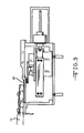
- FIG. 3 is a side elevantional view, with parts removed, of the apparatus of FIG. 2 ;
- FIG. 4 is a perspective view of the finger guide of the present invention for use with another type of scanner
- FIG. 5 is a diagrammatic view further illustrating an alternative form of guide post of the finger guide of the present invention.
- FIGS. 6A-6C are diagrammatic views illustrating alternative finger sensing arrangements for use in the finger guide of the present invention.
- FIG. 7 is a perspective view of the finger guide of the present invention used in another type of scanner
- An overall improvement can be made to all live scan fingerprint readers by providing the automatic guide as shown in FIGS. 1A and 1B for properly positioning the finger horizontally, vertically, and without rotation. Doing so will ensure that the user's finger will be in the optimum position of the fingerprint platen, without distortion, thereby enabling the highest possible system accuracy. Furthermore, the system is able to do this without the help of the user, an attendant, or a display such as a PC Monitor. This makes the system user friendly and low cost, thereby enabling the use of these devices in unattended applications.
- the feedback could be visual such as LEDs, audible, or both.
- the position as to where the finger comes to rest on the platen can then be determined. This can be done manually, or automatically by the system through a variety of image processing techniques.
- the arrangement shown in FIGS. 1A and 1B is provided on the operative surface of a fingerprint scanner, typically the top surface 10 of the scanner.
- the scanner can be any of the types previously mentioned hereinabove.
- the enrollment and verification process would work in the following manner.
- the user places their left or right hand 12 down onto the surface 10 of the fingerprint scanner and ensures proper finger placement against the guide post 14 or 16 and stop post 18 or 20 as indicated by feedback sensors.
- the system scans a large portion of the finger on the scanner platen 26 and determines the location of the tip of the finger.
- the large portion of the finger must only be scanned during the time of enrollment in order to ensure that the tip of the finger is located and the complete fingerprint image is captured. This increased scan time during the enrollment process is not needed during the verification process and would therefore be accepted by the users of the system.
- the system records the fingerprint image or template, the location of the tip of the finger, and any other pertinent information such as PIN code.
- the first approach is ideally suited for fingerprint scanners that scan the finger mechanically, such as the ultrasonic scanner 30 shown in FIGS. 2 and 3 .
- the scanner of FIGS. 2 and 3 is similar to that shown and described in U.S. Pat. No. 5,647,364 issued Jul. 15, 1997, the disclosure of which is hereby incorporated by reference.
- the second approach is ideally suited for scanners 40 that do not scan the finger mechanically as shown in FIG. 4
- the verification process for mechanical scanners is as follows.
- the user enters their token ID such as the PIN code recorded at the time of enrollment.
- the system retrieves the fingerprint information that is to be compared, along with the location of the tip of the finger.
- the system uses a stepper motor or other motion controlling type of device, positions the scan head to the proper position under the platen for that individual in order to scan the finger. Since the scan head is in an optimum position, only a normal size area of the finger needs to be scanned, thereby minimizing the scan time.
- the user places their left or right hand down onto the surface of the fingerprint scanner as they did during enrollment and ensures proper finger placement against the guide post and stop post as indicated by the feedback sensors. The finger is scanned and the identity verification process takes place.
- the verification process for non-mechanical scanners is as follows.
- moving the solid state imaging array to directly under the finger may or may not be feasible.
- the guide post and stop post could be moved and the image array kept stationary. In this manner, the end result is the same in that the tip of the finger rests directly over the imaging sensor.
- the finger guide has in an unattended verification mode of operation, there are even advantages when used in a non-verification mode or operations, i.e., a cold search application.
- the accuracy and speed of identifying an individual is directly related to finger placement on the platen.
- the matching algorithm In order to compare two images, the matching algorithm must allow for translation and rotation. The tighter the control on these two degrees of freedom, the faster a match can be performed, with greater accuracy.
- the enrollment process would store both the fingerprint image and the location on the platen where the finger was found.
- the second parameter, the location on the platen where the finger was found is directly related to the length of the finger as measured from the length of the stop post to the tip of the scanned image. Therefore, it can be used as a discriminator into the large database of fingerprint images.
- the system would not automatically search for the top of the finger and begin scanning. Only the portion of the database associated with that particular length of finger would have to be searched, thereby not only improving accuracy (less images to search), but also decreasing the overall search time.
- FIG. 5 shows an alternative form of guide post provided with a pressure sensitive membrane type switch 52 located along the surface of the guide post which is to be contacted by the finger.
- the arrangement can be elongated and comprising a pair of pads of conductive ink.
- Alternative approaches such as impedance, resistive or capacitive switches and infrared sensitive elements also can be employed.
- FIGS. 6A-6C illustrate alternative finger sensing arrangements for use in the finger guide of the present invention.
- Each of the arrangements is in the form of a membrane switch construction and would be located on a surface of the scanner in relation to the active scan area.
- the arrangement of FIG. 6A includes a series of individual keypad conductive ink buttons 60 , 62 , 64 and 66 along a row or substantially linear path.
- FIG. 6B illustrates a single long continuous strip 70 of conductive ink for sensing any part of the finger.
- FIG. 6C shows an arrangement of many individual strips 74 (circuits) which functions to indicate whether or not the finger is in place and to provide an indication of the finger length. The strips are along a row or substantially linear path.
- FIG. 7 shows the finger guide of the present invention in a portable fingerprint scanner 80 adapted primarily for law enforcement use.
- the finger guide post 82 is located on the top surface 84 of the scanner in relation to the fingerprint scan area.
- the scanner can be of the type shown in the above-referenced U.S. Pat. No. 5,647,364 adapted for battery operation.
- the scanner can be connected to a computer in the law enforcement vehicle either via the hard wire connection or the RF communication link indicated in FIG. 7 . That is for the purpose of storing and processing the fingerprint images down-loaded from the scanner.
- the device is held by the law enforcement officer by means of the handle 90 , the subject places his finger on the scanner including the scan area or platen 92 and when the finger is properly positioned an indication is provided by the LED 94 as previously described, whereupon the scanner is activated by the officer simply by squeezing the trigger 96 and if a fingerprint image is obtained this is indicated by another LED.
Abstract
Description
Claims (7)
Priority Applications (1)
| Application Number | Priority Date | Filing Date | Title |
|---|---|---|---|
| US09/659,772 US6937748B1 (en) | 1999-09-10 | 2000-09-11 | Left hand right hand invariant dynamic finger positioning guide |
Applications Claiming Priority (2)
| Application Number | Priority Date | Filing Date | Title |
|---|---|---|---|
| US15318099P | 1999-09-10 | 1999-09-10 | |
| US09/659,772 US6937748B1 (en) | 1999-09-10 | 2000-09-11 | Left hand right hand invariant dynamic finger positioning guide |
Publications (1)
| Publication Number | Publication Date |
|---|---|
| US6937748B1 true US6937748B1 (en) | 2005-08-30 |
Family
ID=34864196
Family Applications (1)
| Application Number | Title | Priority Date | Filing Date |
|---|---|---|---|
| US09/659,772 Expired - Fee Related US6937748B1 (en) | 1999-09-10 | 2000-09-11 | Left hand right hand invariant dynamic finger positioning guide |
Country Status (1)
| Country | Link |
|---|---|
| US (1) | US6937748B1 (en) |
Cited By (55)
| Publication number | Priority date | Publication date | Assignee | Title |
|---|---|---|---|---|
| US20040057606A1 (en) * | 2002-09-25 | 2004-03-25 | The Hong Kong Polytechnic University | Apparatus for capturing a palmprint image |
| US20040136575A1 (en) * | 2001-05-19 | 2004-07-15 | Moon-Sung Hwang | Fingerprint recognition apparatus with automatic finger contact sensing function |
| US20050244039A1 (en) * | 2004-04-23 | 2005-11-03 | Validity Sensors, Inc. | Methods and apparatus for acquiring a swiped fingerprint image |
| US20060067566A1 (en) * | 2004-09-29 | 2006-03-30 | Nec Corporation | Plain four-finger image determination device, plain four-finger image determination method and plain four-finger determination program |
| US20060115132A1 (en) * | 2004-12-01 | 2006-06-01 | Schneider John K | Fingerprint scanning station |
| US20090123041A1 (en) * | 2007-11-12 | 2009-05-14 | Fujitsu Limited | Guide apparatus, image pickup apparatus, image pickup system, and guide method |
| US20110031504A1 (en) * | 2006-04-20 | 2011-02-10 | Quick Nathaniel R | Apparatus and method for increasing thermal conductivity of a substrate |
| US20110090541A1 (en) * | 2009-10-15 | 2011-04-21 | Jack Harper | Fingerprint scanning systems and methods |
| US8005276B2 (en) | 2008-04-04 | 2011-08-23 | Validity Sensors, Inc. | Apparatus and method for reducing parasitic capacitive coupling and noise in fingerprint sensing circuits |
| US8107212B2 (en) | 2007-04-30 | 2012-01-31 | Validity Sensors, Inc. | Apparatus and method for protecting fingerprint sensing circuitry from electrostatic discharge |
| US8116540B2 (en) | 2008-04-04 | 2012-02-14 | Validity Sensors, Inc. | Apparatus and method for reducing noise in fingerprint sensing circuits |
| US8131026B2 (en) | 2004-04-16 | 2012-03-06 | Validity Sensors, Inc. | Method and apparatus for fingerprint image reconstruction |
| US8165355B2 (en) | 2006-09-11 | 2012-04-24 | Validity Sensors, Inc. | Method and apparatus for fingerprint motion tracking using an in-line array for use in navigation applications |
| US8175345B2 (en) | 2004-04-16 | 2012-05-08 | Validity Sensors, Inc. | Unitized ergonomic two-dimensional fingerprint motion tracking device and method |
| US8204281B2 (en) | 2007-12-14 | 2012-06-19 | Validity Sensors, Inc. | System and method to remove artifacts from fingerprint sensor scans |
| US8224044B2 (en) | 2004-10-04 | 2012-07-17 | Validity Sensors, Inc. | Fingerprint sensing assemblies and methods of making |
| US8229184B2 (en) | 2004-04-16 | 2012-07-24 | Validity Sensors, Inc. | Method and algorithm for accurate finger motion tracking |
| US8278946B2 (en) | 2009-01-15 | 2012-10-02 | Validity Sensors, Inc. | Apparatus and method for detecting finger activity on a fingerprint sensor |
| US8276816B2 (en) | 2007-12-14 | 2012-10-02 | Validity Sensors, Inc. | Smart card system with ergonomic fingerprint sensor and method of using |
| US8290150B2 (en) | 2007-05-11 | 2012-10-16 | Validity Sensors, Inc. | Method and system for electronically securing an electronic device using physically unclonable functions |
| US8331096B2 (en) | 2010-08-20 | 2012-12-11 | Validity Sensors, Inc. | Fingerprint acquisition expansion card apparatus |
| US8358815B2 (en) | 2004-04-16 | 2013-01-22 | Validity Sensors, Inc. | Method and apparatus for two-dimensional finger motion tracking and control |
| US8374407B2 (en) | 2009-01-28 | 2013-02-12 | Validity Sensors, Inc. | Live finger detection |
| US8391568B2 (en) | 2008-11-10 | 2013-03-05 | Validity Sensors, Inc. | System and method for improved scanning of fingerprint edges |
| US8421890B2 (en) | 2010-01-15 | 2013-04-16 | Picofield Technologies, Inc. | Electronic imager using an impedance sensor grid array and method of making |
| US8447077B2 (en) | 2006-09-11 | 2013-05-21 | Validity Sensors, Inc. | Method and apparatus for fingerprint motion tracking using an in-line array |
| CN103189894A (en) * | 2010-11-08 | 2013-07-03 | 日本电气株式会社 | Biometric authentication apparatus and biometric authentication method |
| US8538097B2 (en) | 2011-01-26 | 2013-09-17 | Validity Sensors, Inc. | User input utilizing dual line scanner apparatus and method |
| US8594393B2 (en) | 2011-01-26 | 2013-11-26 | Validity Sensors | System for and method of image reconstruction with dual line scanner using line counts |
| US8600122B2 (en) | 2009-01-15 | 2013-12-03 | Validity Sensors, Inc. | Apparatus and method for culling substantially redundant data in fingerprint sensing circuits |
| US20140086460A1 (en) * | 2004-11-03 | 2014-03-27 | Pen-One, Inc. | Finger guide device with circumscribing ring |
| US8698594B2 (en) | 2008-07-22 | 2014-04-15 | Synaptics Incorporated | System, device and method for securing a user device component by authenticating the user of a biometric sensor by performance of a replication of a portion of an authentication process performed at a remote computing device |
| US8716613B2 (en) | 2010-03-02 | 2014-05-06 | Synaptics Incoporated | Apparatus and method for electrostatic discharge protection |
| US8791792B2 (en) | 2010-01-15 | 2014-07-29 | Idex Asa | Electronic imager using an impedance sensor grid array mounted on or about a switch and method of making |
| US8866347B2 (en) | 2010-01-15 | 2014-10-21 | Idex Asa | Biometric image sensing |
| US9001040B2 (en) | 2010-06-02 | 2015-04-07 | Synaptics Incorporated | Integrated fingerprint sensor and navigation device |
| US9137438B2 (en) | 2012-03-27 | 2015-09-15 | Synaptics Incorporated | Biometric object sensor and method |
| US9152838B2 (en) | 2012-03-29 | 2015-10-06 | Synaptics Incorporated | Fingerprint sensor packagings and methods |
| US9195877B2 (en) | 2011-12-23 | 2015-11-24 | Synaptics Incorporated | Methods and devices for capacitive image sensing |
| US9251329B2 (en) | 2012-03-27 | 2016-02-02 | Synaptics Incorporated | Button depress wakeup and wakeup strategy |
| US9268991B2 (en) | 2012-03-27 | 2016-02-23 | Synaptics Incorporated | Method of and system for enrolling and matching biometric data |
| US9274553B2 (en) | 2009-10-30 | 2016-03-01 | Synaptics Incorporated | Fingerprint sensor and integratable electronic display |
| US9336428B2 (en) | 2009-10-30 | 2016-05-10 | Synaptics Incorporated | Integrated fingerprint sensor and display |
| US9400911B2 (en) | 2009-10-30 | 2016-07-26 | Synaptics Incorporated | Fingerprint sensor and integratable electronic display |
| US9406580B2 (en) | 2011-03-16 | 2016-08-02 | Synaptics Incorporated | Packaging for fingerprint sensors and methods of manufacture |
| US9600709B2 (en) | 2012-03-28 | 2017-03-21 | Synaptics Incorporated | Methods and systems for enrolling biometric data |
| US9665762B2 (en) | 2013-01-11 | 2017-05-30 | Synaptics Incorporated | Tiered wakeup strategy |
| US9666635B2 (en) | 2010-02-19 | 2017-05-30 | Synaptics Incorporated | Fingerprint sensing circuit |
| US9785299B2 (en) | 2012-01-03 | 2017-10-10 | Synaptics Incorporated | Structures and manufacturing methods for glass covered electronic devices |
| US9798917B2 (en) | 2012-04-10 | 2017-10-24 | Idex Asa | Biometric sensing |
| US10043052B2 (en) | 2011-10-27 | 2018-08-07 | Synaptics Incorporated | Electronic device packages and methods |
| US11341348B2 (en) * | 2020-03-23 | 2022-05-24 | Alitheon, Inc. | Hand biometrics system and method using digital fingerprints |
| US11488413B2 (en) | 2019-02-06 | 2022-11-01 | Alitheon, Inc. | Object change detection and measurement using digital fingerprints |
| US11682026B2 (en) | 2016-02-19 | 2023-06-20 | Alitheon, Inc. | Personal history in track and trace system |
| US11922753B2 (en) | 2019-10-17 | 2024-03-05 | Alitheon, Inc. | Securing composite objects using digital fingerprints |
Citations (9)
| Publication number | Priority date | Publication date | Assignee | Title |
|---|---|---|---|---|
| US3576538A (en) * | 1969-04-14 | 1971-04-27 | Identimation Corp | Finger dimension comparison identification system |
| US3584958A (en) * | 1968-09-13 | 1971-06-15 | Indentimation Corp | Identification system |
| US3614737A (en) * | 1969-09-08 | 1971-10-19 | Dactylog Inc | Method and apparatus for individual recognition |
| US3668633A (en) * | 1970-01-29 | 1972-06-06 | Dactylog Co | Orientation and linear scan device for use in an apparatus for individual recognition |
| US3804524A (en) * | 1972-08-31 | 1974-04-16 | G Nanus | Apparatus for controlling fingerprint identification |
| US4357597A (en) * | 1980-08-26 | 1982-11-02 | Palmguard, Inc. | Palm-positioning and system-actuating mechanism |
| US5177802A (en) * | 1990-03-07 | 1993-01-05 | Sharp Kabushiki Kaisha | Fingerprint input apparatus |
| US5483601A (en) * | 1992-02-10 | 1996-01-09 | Keith Faulkner | Apparatus and method for biometric identification using silhouette and displacement images of a portion of a person's hand |
| US6198836B1 (en) * | 1996-08-27 | 2001-03-06 | A-Tronic Mgm Ag | Method and device for recognizing non-unrolled fingerprints |
-
2000
- 2000-09-11 US US09/659,772 patent/US6937748B1/en not_active Expired - Fee Related
Patent Citations (9)
| Publication number | Priority date | Publication date | Assignee | Title |
|---|---|---|---|---|
| US3584958A (en) * | 1968-09-13 | 1971-06-15 | Indentimation Corp | Identification system |
| US3576538A (en) * | 1969-04-14 | 1971-04-27 | Identimation Corp | Finger dimension comparison identification system |
| US3614737A (en) * | 1969-09-08 | 1971-10-19 | Dactylog Inc | Method and apparatus for individual recognition |
| US3668633A (en) * | 1970-01-29 | 1972-06-06 | Dactylog Co | Orientation and linear scan device for use in an apparatus for individual recognition |
| US3804524A (en) * | 1972-08-31 | 1974-04-16 | G Nanus | Apparatus for controlling fingerprint identification |
| US4357597A (en) * | 1980-08-26 | 1982-11-02 | Palmguard, Inc. | Palm-positioning and system-actuating mechanism |
| US5177802A (en) * | 1990-03-07 | 1993-01-05 | Sharp Kabushiki Kaisha | Fingerprint input apparatus |
| US5483601A (en) * | 1992-02-10 | 1996-01-09 | Keith Faulkner | Apparatus and method for biometric identification using silhouette and displacement images of a portion of a person's hand |
| US6198836B1 (en) * | 1996-08-27 | 2001-03-06 | A-Tronic Mgm Ag | Method and device for recognizing non-unrolled fingerprints |
Cited By (89)
| Publication number | Priority date | Publication date | Assignee | Title |
|---|---|---|---|---|
| US20040136575A1 (en) * | 2001-05-19 | 2004-07-15 | Moon-Sung Hwang | Fingerprint recognition apparatus with automatic finger contact sensing function |
| US7266226B2 (en) * | 2001-05-19 | 2007-09-04 | Keico Hightech Inc. | Fingerprint recognition apparatus with automatic finger contact sensing function |
| US20040057606A1 (en) * | 2002-09-25 | 2004-03-25 | The Hong Kong Polytechnic University | Apparatus for capturing a palmprint image |
| US8131026B2 (en) | 2004-04-16 | 2012-03-06 | Validity Sensors, Inc. | Method and apparatus for fingerprint image reconstruction |
| US8315444B2 (en) | 2004-04-16 | 2012-11-20 | Validity Sensors, Inc. | Unitized ergonomic two-dimensional fingerprint motion tracking device and method |
| US8811688B2 (en) | 2004-04-16 | 2014-08-19 | Synaptics Incorporated | Method and apparatus for fingerprint image reconstruction |
| US8358815B2 (en) | 2004-04-16 | 2013-01-22 | Validity Sensors, Inc. | Method and apparatus for two-dimensional finger motion tracking and control |
| US8229184B2 (en) | 2004-04-16 | 2012-07-24 | Validity Sensors, Inc. | Method and algorithm for accurate finger motion tracking |
| US8175345B2 (en) | 2004-04-16 | 2012-05-08 | Validity Sensors, Inc. | Unitized ergonomic two-dimensional fingerprint motion tracking device and method |
| US20050244039A1 (en) * | 2004-04-23 | 2005-11-03 | Validity Sensors, Inc. | Methods and apparatus for acquiring a swiped fingerprint image |
| US8077935B2 (en) * | 2004-04-23 | 2011-12-13 | Validity Sensors, Inc. | Methods and apparatus for acquiring a swiped fingerprint image |
| US20060067566A1 (en) * | 2004-09-29 | 2006-03-30 | Nec Corporation | Plain four-finger image determination device, plain four-finger image determination method and plain four-finger determination program |
| US8224044B2 (en) | 2004-10-04 | 2012-07-17 | Validity Sensors, Inc. | Fingerprint sensing assemblies and methods of making |
| US8867799B2 (en) | 2004-10-04 | 2014-10-21 | Synaptics Incorporated | Fingerprint sensing assemblies and methods of making |
| US20140086460A1 (en) * | 2004-11-03 | 2014-03-27 | Pen-One, Inc. | Finger guide device with circumscribing ring |
| US20160188947A1 (en) * | 2004-11-03 | 2016-06-30 | Pen-One, Inc. | Finger guide device with capacitive sensor |
| US9830493B2 (en) * | 2004-11-03 | 2017-11-28 | Pen-One Acquisition Group, Llc | Finger guide device with capacitive sensor |
| US7558410B2 (en) * | 2004-12-01 | 2009-07-07 | Ultra-Scan Corporation | Fingerprint scanning station |
| US20060115132A1 (en) * | 2004-12-01 | 2006-06-01 | Schneider John K | Fingerprint scanning station |
| US20110031504A1 (en) * | 2006-04-20 | 2011-02-10 | Quick Nathaniel R | Apparatus and method for increasing thermal conductivity of a substrate |
| US8165355B2 (en) | 2006-09-11 | 2012-04-24 | Validity Sensors, Inc. | Method and apparatus for fingerprint motion tracking using an in-line array for use in navigation applications |
| US8693736B2 (en) | 2006-09-11 | 2014-04-08 | Synaptics Incorporated | System for determining the motion of a fingerprint surface with respect to a sensor surface |
| US8447077B2 (en) | 2006-09-11 | 2013-05-21 | Validity Sensors, Inc. | Method and apparatus for fingerprint motion tracking using an in-line array |
| US8107212B2 (en) | 2007-04-30 | 2012-01-31 | Validity Sensors, Inc. | Apparatus and method for protecting fingerprint sensing circuitry from electrostatic discharge |
| US8290150B2 (en) | 2007-05-11 | 2012-10-16 | Validity Sensors, Inc. | Method and system for electronically securing an electronic device using physically unclonable functions |
| US8326005B2 (en) * | 2007-11-12 | 2012-12-04 | Fujitsu Limited | Guide apparatus, image pickup apparatus, image pickup system, and guide method |
| US20090123041A1 (en) * | 2007-11-12 | 2009-05-14 | Fujitsu Limited | Guide apparatus, image pickup apparatus, image pickup system, and guide method |
| US8204281B2 (en) | 2007-12-14 | 2012-06-19 | Validity Sensors, Inc. | System and method to remove artifacts from fingerprint sensor scans |
| US8276816B2 (en) | 2007-12-14 | 2012-10-02 | Validity Sensors, Inc. | Smart card system with ergonomic fingerprint sensor and method of using |
| USRE45650E1 (en) | 2008-04-04 | 2015-08-11 | Synaptics Incorporated | Apparatus and method for reducing parasitic capacitive coupling and noise in fingerprint sensing circuits |
| US8520913B2 (en) | 2008-04-04 | 2013-08-27 | Validity Sensors, Inc. | Apparatus and method for reducing noise in fingerprint sensing circuits |
| US8787632B2 (en) | 2008-04-04 | 2014-07-22 | Synaptics Incorporated | Apparatus and method for reducing noise in fingerprint sensing circuits |
| US8116540B2 (en) | 2008-04-04 | 2012-02-14 | Validity Sensors, Inc. | Apparatus and method for reducing noise in fingerprint sensing circuits |
| US8005276B2 (en) | 2008-04-04 | 2011-08-23 | Validity Sensors, Inc. | Apparatus and method for reducing parasitic capacitive coupling and noise in fingerprint sensing circuits |
| US8698594B2 (en) | 2008-07-22 | 2014-04-15 | Synaptics Incorporated | System, device and method for securing a user device component by authenticating the user of a biometric sensor by performance of a replication of a portion of an authentication process performed at a remote computing device |
| US8391568B2 (en) | 2008-11-10 | 2013-03-05 | Validity Sensors, Inc. | System and method for improved scanning of fingerprint edges |
| US8278946B2 (en) | 2009-01-15 | 2012-10-02 | Validity Sensors, Inc. | Apparatus and method for detecting finger activity on a fingerprint sensor |
| US8593160B2 (en) | 2009-01-15 | 2013-11-26 | Validity Sensors, Inc. | Apparatus and method for finger activity on a fingerprint sensor |
| US8600122B2 (en) | 2009-01-15 | 2013-12-03 | Validity Sensors, Inc. | Apparatus and method for culling substantially redundant data in fingerprint sensing circuits |
| US8374407B2 (en) | 2009-01-28 | 2013-02-12 | Validity Sensors, Inc. | Live finger detection |
| US8331775B2 (en) * | 2009-10-15 | 2012-12-11 | Jack Harper | Fingerprint scanning systems and methods |
| US20110090541A1 (en) * | 2009-10-15 | 2011-04-21 | Jack Harper | Fingerprint scanning systems and methods |
| US9400911B2 (en) | 2009-10-30 | 2016-07-26 | Synaptics Incorporated | Fingerprint sensor and integratable electronic display |
| US9274553B2 (en) | 2009-10-30 | 2016-03-01 | Synaptics Incorporated | Fingerprint sensor and integratable electronic display |
| US9336428B2 (en) | 2009-10-30 | 2016-05-10 | Synaptics Incorporated | Integrated fingerprint sensor and display |
| US8791792B2 (en) | 2010-01-15 | 2014-07-29 | Idex Asa | Electronic imager using an impedance sensor grid array mounted on or about a switch and method of making |
| US8421890B2 (en) | 2010-01-15 | 2013-04-16 | Picofield Technologies, Inc. | Electronic imager using an impedance sensor grid array and method of making |
| US8866347B2 (en) | 2010-01-15 | 2014-10-21 | Idex Asa | Biometric image sensing |
| US10115001B2 (en) | 2010-01-15 | 2018-10-30 | Idex Asa | Biometric image sensing |
| US11080504B2 (en) | 2010-01-15 | 2021-08-03 | Idex Biometrics Asa | Biometric image sensing |
| US9659208B2 (en) | 2010-01-15 | 2017-05-23 | Idex Asa | Biometric image sensing |
| US9600704B2 (en) | 2010-01-15 | 2017-03-21 | Idex Asa | Electronic imager using an impedance sensor grid array and method of making |
| US10592719B2 (en) | 2010-01-15 | 2020-03-17 | Idex Biometrics Asa | Biometric image sensing |
| US9268988B2 (en) | 2010-01-15 | 2016-02-23 | Idex Asa | Biometric image sensing |
| US9666635B2 (en) | 2010-02-19 | 2017-05-30 | Synaptics Incorporated | Fingerprint sensing circuit |
| US8716613B2 (en) | 2010-03-02 | 2014-05-06 | Synaptics Incoporated | Apparatus and method for electrostatic discharge protection |
| US9001040B2 (en) | 2010-06-02 | 2015-04-07 | Synaptics Incorporated | Integrated fingerprint sensor and navigation device |
| US8331096B2 (en) | 2010-08-20 | 2012-12-11 | Validity Sensors, Inc. | Fingerprint acquisition expansion card apparatus |
| CN103189894B (en) * | 2010-11-08 | 2017-03-08 | 日本电气株式会社 | Biological authentication apparatus and biological authentication method |
| US9323971B2 (en) * | 2010-11-08 | 2016-04-26 | Nec Corporation | Biometric authentication apparatus and biometric authentication method |
| US20130182921A1 (en) * | 2010-11-08 | 2013-07-18 | Nec Corporation | Biometric authentication apparatus and biometric authentication method |
| CN103189894A (en) * | 2010-11-08 | 2013-07-03 | 日本电气株式会社 | Biometric authentication apparatus and biometric authentication method |
| US8594393B2 (en) | 2011-01-26 | 2013-11-26 | Validity Sensors | System for and method of image reconstruction with dual line scanner using line counts |
| US8811723B2 (en) | 2011-01-26 | 2014-08-19 | Synaptics Incorporated | User input utilizing dual line scanner apparatus and method |
| US8538097B2 (en) | 2011-01-26 | 2013-09-17 | Validity Sensors, Inc. | User input utilizing dual line scanner apparatus and method |
| US8929619B2 (en) | 2011-01-26 | 2015-01-06 | Synaptics Incorporated | System and method of image reconstruction with dual line scanner using line counts |
| US9406580B2 (en) | 2011-03-16 | 2016-08-02 | Synaptics Incorporated | Packaging for fingerprint sensors and methods of manufacture |
| USRE47890E1 (en) | 2011-03-16 | 2020-03-03 | Amkor Technology, Inc. | Packaging for fingerprint sensors and methods of manufacture |
| US10636717B2 (en) | 2011-03-16 | 2020-04-28 | Amkor Technology, Inc. | Packaging for fingerprint sensors and methods of manufacture |
| US10043052B2 (en) | 2011-10-27 | 2018-08-07 | Synaptics Incorporated | Electronic device packages and methods |
| US9195877B2 (en) | 2011-12-23 | 2015-11-24 | Synaptics Incorporated | Methods and devices for capacitive image sensing |
| US9785299B2 (en) | 2012-01-03 | 2017-10-10 | Synaptics Incorporated | Structures and manufacturing methods for glass covered electronic devices |
| US9268991B2 (en) | 2012-03-27 | 2016-02-23 | Synaptics Incorporated | Method of and system for enrolling and matching biometric data |
| US9137438B2 (en) | 2012-03-27 | 2015-09-15 | Synaptics Incorporated | Biometric object sensor and method |
| US9697411B2 (en) | 2012-03-27 | 2017-07-04 | Synaptics Incorporated | Biometric object sensor and method |
| US9824200B2 (en) | 2012-03-27 | 2017-11-21 | Synaptics Incorporated | Wakeup strategy using a biometric sensor |
| US9251329B2 (en) | 2012-03-27 | 2016-02-02 | Synaptics Incorporated | Button depress wakeup and wakeup strategy |
| US10346699B2 (en) | 2012-03-28 | 2019-07-09 | Synaptics Incorporated | Methods and systems for enrolling biometric data |
| US9600709B2 (en) | 2012-03-28 | 2017-03-21 | Synaptics Incorporated | Methods and systems for enrolling biometric data |
| US9152838B2 (en) | 2012-03-29 | 2015-10-06 | Synaptics Incorporated | Fingerprint sensor packagings and methods |
| US10101851B2 (en) | 2012-04-10 | 2018-10-16 | Idex Asa | Display with integrated touch screen and fingerprint sensor |
| US10114497B2 (en) | 2012-04-10 | 2018-10-30 | Idex Asa | Biometric sensing |
| US10088939B2 (en) | 2012-04-10 | 2018-10-02 | Idex Asa | Biometric sensing |
| US9798917B2 (en) | 2012-04-10 | 2017-10-24 | Idex Asa | Biometric sensing |
| US9665762B2 (en) | 2013-01-11 | 2017-05-30 | Synaptics Incorporated | Tiered wakeup strategy |
| US11682026B2 (en) | 2016-02-19 | 2023-06-20 | Alitheon, Inc. | Personal history in track and trace system |
| US11488413B2 (en) | 2019-02-06 | 2022-11-01 | Alitheon, Inc. | Object change detection and measurement using digital fingerprints |
| US11922753B2 (en) | 2019-10-17 | 2024-03-05 | Alitheon, Inc. | Securing composite objects using digital fingerprints |
| US11341348B2 (en) * | 2020-03-23 | 2022-05-24 | Alitheon, Inc. | Hand biometrics system and method using digital fingerprints |
Similar Documents
| Publication | Publication Date | Title |
|---|---|---|
| US6937748B1 (en) | Left hand right hand invariant dynamic finger positioning guide | |
| US7502497B2 (en) | Method and system for extracting an area of interest from within an image of a biological surface | |
| US9830493B2 (en) | Finger guide device with capacitive sensor | |
| US7103201B2 (en) | Methods for capturing fingerprint images using a moving platen | |
| JP5831018B2 (en) | Biometric authentication device and method for adjusting user's hand position in biometric authentication device | |
| US8391568B2 (en) | System and method for improved scanning of fingerprint edges | |
| US6501847B2 (en) | System for promoting correct finger placement in a fingerprint reader | |
| US8077935B2 (en) | Methods and apparatus for acquiring a swiped fingerprint image | |
| US9280695B2 (en) | Apparatus and method for determining sequencing of fingers in images to a two-finger scanner of fingerprint images | |
| EP1966739B1 (en) | Biometric information detection using sweep-type imager | |
| US20050180619A1 (en) | Biometric imaging system and method | |
| EP1139301A3 (en) | An apparatus for identity verification, a system for identity verification, a card for identity verification and a method for identity verification based on identification by biometrics | |
| GB2400713A (en) | Combined optical fingerprint recogniser and navigation control | |
| AU2005301969A1 (en) | Finger guide device | |
| JP2006285487A (en) | Biological information detection apparatus and biological authentication apparatus | |
| US6917694B1 (en) | Surface shape recognition apparatus and method | |
| CA2582886C (en) | Finger guide device | |
| WO2001018740A1 (en) | Left hand right hand invariant dynamic finger positioning guide | |
| JPH02501684A (en) | fingerprint analysis | |
| US7671976B2 (en) | Systems and methods of using a flexible imaging surface to capture a rolled fingerprint | |
| AU2014262191B2 (en) | Finger guide device | |
| JPS6015779A (en) | Fingerprint collator | |
| JPH1049675A (en) | Individual body confirmation device | |
| JPH01298473A (en) | Pattern picture processor | |
| JPH04359384A (en) | Finger print signal input device |
Legal Events
| Date | Code | Title | Description |
|---|---|---|---|
| AS | Assignment |
Owner name: ULTRA-SCAN CORPORATION, NEW YORK Free format text: ASSIGNMENT OF ASSIGNORS INTEREST;ASSIGNORS:SCHNEIDER, JOHN K.;GOJEVIC, STEPHEN M.;KEENEY, FRANK W.;AND OTHERS;REEL/FRAME:011595/0632;SIGNING DATES FROM 20010201 TO 20010209 |
|
| CC | Certificate of correction | ||
| FPAY | Fee payment |
Year of fee payment: 4 |
|
| FPAY | Fee payment |
Year of fee payment: 8 |
|
| AS | Assignment |
Owner name: QUALCOMM INCORPORATED, CALIFORNIA Free format text: ASSIGNMENT OF ASSIGNORS INTEREST;ASSIGNOR:ULTRA-SCAN CORPORATION;REEL/FRAME:030416/0069 Effective date: 20130507 |
|
| REMI | Maintenance fee reminder mailed | ||
| LAPS | Lapse for failure to pay maintenance fees |
Free format text: PATENT EXPIRED FOR FAILURE TO PAY MAINTENANCE FEES (ORIGINAL EVENT CODE: EXP.) |
|
| STCH | Information on status: patent discontinuation |
Free format text: PATENT EXPIRED DUE TO NONPAYMENT OF MAINTENANCE FEES UNDER 37 CFR 1.362 |
|
| FP | Lapsed due to failure to pay maintenance fee |
Effective date: 20170830 |