US6831678B1 - Autostereoscopic display - Google Patents
Autostereoscopic display Download PDFInfo
- Publication number
- US6831678B1 US6831678B1 US09/446,007 US44600799A US6831678B1 US 6831678 B1 US6831678 B1 US 6831678B1 US 44600799 A US44600799 A US 44600799A US 6831678 B1 US6831678 B1 US 6831678B1
- Authority
- US
- United States
- Prior art keywords
- display
- screen
- image
- dimensional
- liquid crystal
- Prior art date
- Legal status (The legal status is an assumption and is not a legal conclusion. Google has not performed a legal analysis and makes no representation as to the accuracy of the status listed.)
- Expired - Lifetime
Links
- 239000004973 liquid crystal related substance Substances 0.000 claims description 65
- 230000003287 optical effect Effects 0.000 claims description 29
- 239000000463 material Substances 0.000 claims description 12
- 239000011159 matrix material Substances 0.000 claims description 9
- 230000008859 change Effects 0.000 claims description 7
- 239000011344 liquid material Substances 0.000 claims description 2
- 238000003491 array Methods 0.000 description 15
- 230000000694 effects Effects 0.000 description 13
- 238000009987 spinning Methods 0.000 description 11
- 239000005262 ferroelectric liquid crystals (FLCs) Substances 0.000 description 10
- 238000009826 distribution Methods 0.000 description 9
- 230000006870 function Effects 0.000 description 9
- 238000013459 approach Methods 0.000 description 8
- 230000008901 benefit Effects 0.000 description 8
- 210000003128 head Anatomy 0.000 description 8
- 238000000034 method Methods 0.000 description 8
- 238000005516 engineering process Methods 0.000 description 7
- 238000004519 manufacturing process Methods 0.000 description 7
- 238000005286 illumination Methods 0.000 description 6
- 230000008447 perception Effects 0.000 description 6
- 229910021417 amorphous silicon Inorganic materials 0.000 description 5
- 238000002474 experimental method Methods 0.000 description 5
- 230000033001 locomotion Effects 0.000 description 5
- XUIMIQQOPSSXEZ-UHFFFAOYSA-N Silicon Chemical compound [Si] XUIMIQQOPSSXEZ-UHFFFAOYSA-N 0.000 description 4
- 230000006837 decompression Effects 0.000 description 4
- 238000011161 development Methods 0.000 description 4
- 230000018109 developmental process Effects 0.000 description 4
- 239000011521 glass Substances 0.000 description 4
- 238000003384 imaging method Methods 0.000 description 4
- 229910052710 silicon Inorganic materials 0.000 description 4
- 239000010703 silicon Substances 0.000 description 4
- 238000013461 design Methods 0.000 description 3
- 238000010586 diagram Methods 0.000 description 3
- 239000000203 mixture Substances 0.000 description 3
- 238000011160 research Methods 0.000 description 3
- 239000007787 solid Substances 0.000 description 3
- OAICVXFJPJFONN-UHFFFAOYSA-N Phosphorus Chemical compound [P] OAICVXFJPJFONN-UHFFFAOYSA-N 0.000 description 2
- 239000004990 Smectic liquid crystal Substances 0.000 description 2
- 230000009471 action Effects 0.000 description 2
- 230000005540 biological transmission Effects 0.000 description 2
- 230000001427 coherent effect Effects 0.000 description 2
- 239000013078 crystal Substances 0.000 description 2
- 230000001419 dependent effect Effects 0.000 description 2
- 238000001514 detection method Methods 0.000 description 2
- 230000004438 eyesight Effects 0.000 description 2
- 238000001093 holography Methods 0.000 description 2
- 230000001965 increasing effect Effects 0.000 description 2
- 230000002452 interceptive effect Effects 0.000 description 2
- 239000007788 liquid Substances 0.000 description 2
- 238000001459 lithography Methods 0.000 description 2
- 230000007246 mechanism Effects 0.000 description 2
- 239000013307 optical fiber Substances 0.000 description 2
- 230000008569 process Effects 0.000 description 2
- 210000001747 pupil Anatomy 0.000 description 2
- 238000012552 review Methods 0.000 description 2
- 125000006850 spacer group Chemical group 0.000 description 2
- 238000001356 surgical procedure Methods 0.000 description 2
- 230000001360 synchronised effect Effects 0.000 description 2
- 230000002123 temporal effect Effects 0.000 description 2
- 238000012360 testing method Methods 0.000 description 2
- 230000000007 visual effect Effects 0.000 description 2
- 241001465754 Metazoa Species 0.000 description 1
- 206010028813 Nausea Diseases 0.000 description 1
- 239000004988 Nematic liquid crystal Substances 0.000 description 1
- 241000288906 Primates Species 0.000 description 1
- 108091081062 Repeated sequence (DNA) Proteins 0.000 description 1
- 238000010521 absorption reaction Methods 0.000 description 1
- 230000004308 accommodation Effects 0.000 description 1
- 230000004075 alteration Effects 0.000 description 1
- XAGFODPZIPBFFR-UHFFFAOYSA-N aluminium Chemical compound [Al] XAGFODPZIPBFFR-UHFFFAOYSA-N 0.000 description 1
- 229910052782 aluminium Inorganic materials 0.000 description 1
- 239000004411 aluminium Substances 0.000 description 1
- 238000004458 analytical method Methods 0.000 description 1
- 208000003464 asthenopia Diseases 0.000 description 1
- 239000011324 bead Substances 0.000 description 1
- UHYPYGJEEGLRJD-UHFFFAOYSA-N cadmium(2+);selenium(2-) Chemical compound [Se-2].[Cd+2] UHYPYGJEEGLRJD-UHFFFAOYSA-N 0.000 description 1
- 239000000969 carrier Substances 0.000 description 1
- 230000003749 cleanliness Effects 0.000 description 1
- 238000004891 communication Methods 0.000 description 1
- 238000011960 computer-aided design Methods 0.000 description 1
- 229910003460 diamond Inorganic materials 0.000 description 1
- 239000010432 diamond Substances 0.000 description 1
- 238000010894 electron beam technology Methods 0.000 description 1
- 230000000763 evoking effect Effects 0.000 description 1
- 210000000887 face Anatomy 0.000 description 1
- 238000001914 filtration Methods 0.000 description 1
- 230000003760 hair shine Effects 0.000 description 1
- 230000006872 improvement Effects 0.000 description 1
- 230000010354 integration Effects 0.000 description 1
- 230000003993 interaction Effects 0.000 description 1
- 238000005259 measurement Methods 0.000 description 1
- 238000002844 melting Methods 0.000 description 1
- 230000008018 melting Effects 0.000 description 1
- 238000005459 micromachining Methods 0.000 description 1
- 238000002324 minimally invasive surgery Methods 0.000 description 1
- 238000012986 modification Methods 0.000 description 1
- 230000004048 modification Effects 0.000 description 1
- 230000008693 nausea Effects 0.000 description 1
- 239000000382 optic material Substances 0.000 description 1
- 230000002688 persistence Effects 0.000 description 1
- 229910021420 polycrystalline silicon Inorganic materials 0.000 description 1
- 244000062645 predators Species 0.000 description 1
- 230000002028 premature Effects 0.000 description 1
- 238000007639 printing Methods 0.000 description 1
- 238000012545 processing Methods 0.000 description 1
- 230000000135 prohibitive effect Effects 0.000 description 1
- 230000002035 prolonged effect Effects 0.000 description 1
- 238000011158 quantitative evaluation Methods 0.000 description 1
- 229910052701 rubidium Inorganic materials 0.000 description 1
- IGLNJRXAVVLDKE-UHFFFAOYSA-N rubidium atom Chemical compound [Rb] IGLNJRXAVVLDKE-UHFFFAOYSA-N 0.000 description 1
- 238000012216 screening Methods 0.000 description 1
- 239000004065 semiconductor Substances 0.000 description 1
- 238000004088 simulation Methods 0.000 description 1
- 241000894007 species Species 0.000 description 1
- 238000001228 spectrum Methods 0.000 description 1
- 230000003068 static effect Effects 0.000 description 1
- 238000003860 storage Methods 0.000 description 1
- 239000000758 substrate Substances 0.000 description 1
- 238000010408 sweeping Methods 0.000 description 1
- 238000012546 transfer Methods 0.000 description 1
- 238000013519 translation Methods 0.000 description 1
- 230000014616 translation Effects 0.000 description 1
- 239000012780 transparent material Substances 0.000 description 1
- 239000002699 waste material Substances 0.000 description 1
Images


Classifications
-
- G—PHYSICS
- G03—PHOTOGRAPHY; CINEMATOGRAPHY; ANALOGOUS TECHNIQUES USING WAVES OTHER THAN OPTICAL WAVES; ELECTROGRAPHY; HOLOGRAPHY
- G03H—HOLOGRAPHIC PROCESSES OR APPARATUS
- G03H1/00—Holographic processes or apparatus using light, infrared or ultraviolet waves for obtaining holograms or for obtaining an image from them; Details peculiar thereto
- G03H1/22—Processes or apparatus for obtaining an optical image from holograms
- G03H1/2294—Addressing the hologram to an active spatial light modulator
-
- G—PHYSICS
- G03—PHOTOGRAPHY; CINEMATOGRAPHY; ANALOGOUS TECHNIQUES USING WAVES OTHER THAN OPTICAL WAVES; ELECTROGRAPHY; HOLOGRAPHY
- G03H—HOLOGRAPHIC PROCESSES OR APPARATUS
- G03H1/00—Holographic processes or apparatus using light, infrared or ultraviolet waves for obtaining holograms or for obtaining an image from them; Details peculiar thereto
- G03H1/26—Processes or apparatus specially adapted to produce multiple sub- holograms or to obtain images from them, e.g. multicolour technique
- G03H1/30—Processes or apparatus specially adapted to produce multiple sub- holograms or to obtain images from them, e.g. multicolour technique discrete holograms only
-
- G—PHYSICS
- G03—PHOTOGRAPHY; CINEMATOGRAPHY; ANALOGOUS TECHNIQUES USING WAVES OTHER THAN OPTICAL WAVES; ELECTROGRAPHY; HOLOGRAPHY
- G03H—HOLOGRAPHIC PROCESSES OR APPARATUS
- G03H1/00—Holographic processes or apparatus using light, infrared or ultraviolet waves for obtaining holograms or for obtaining an image from them; Details peculiar thereto
- G03H1/22—Processes or apparatus for obtaining an optical image from holograms
- G03H1/2202—Reconstruction geometries or arrangements
- G03H1/2205—Reconstruction geometries or arrangements using downstream optical component
- G03H2001/221—Element having optical power, e.g. field lens
-
- G—PHYSICS
- G03—PHOTOGRAPHY; CINEMATOGRAPHY; ANALOGOUS TECHNIQUES USING WAVES OTHER THAN OPTICAL WAVES; ELECTROGRAPHY; HOLOGRAPHY
- G03H—HOLOGRAPHIC PROCESSES OR APPARATUS
- G03H1/00—Holographic processes or apparatus using light, infrared or ultraviolet waves for obtaining holograms or for obtaining an image from them; Details peculiar thereto
- G03H1/22—Processes or apparatus for obtaining an optical image from holograms
- G03H1/2202—Reconstruction geometries or arrangements
- G03H2001/2236—Details of the viewing window
- G03H2001/2239—Enlarging the viewing window
-
- G—PHYSICS
- G03—PHOTOGRAPHY; CINEMATOGRAPHY; ANALOGOUS TECHNIQUES USING WAVES OTHER THAN OPTICAL WAVES; ELECTROGRAPHY; HOLOGRAPHY
- G03H—HOLOGRAPHIC PROCESSES OR APPARATUS
- G03H1/00—Holographic processes or apparatus using light, infrared or ultraviolet waves for obtaining holograms or for obtaining an image from them; Details peculiar thereto
- G03H1/22—Processes or apparatus for obtaining an optical image from holograms
- G03H1/2202—Reconstruction geometries or arrangements
- G03H2001/2236—Details of the viewing window
- G03H2001/2242—Multiple viewing windows
-
- G—PHYSICS
- G03—PHOTOGRAPHY; CINEMATOGRAPHY; ANALOGOUS TECHNIQUES USING WAVES OTHER THAN OPTICAL WAVES; ELECTROGRAPHY; HOLOGRAPHY
- G03H—HOLOGRAPHIC PROCESSES OR APPARATUS
- G03H1/00—Holographic processes or apparatus using light, infrared or ultraviolet waves for obtaining holograms or for obtaining an image from them; Details peculiar thereto
- G03H1/22—Processes or apparatus for obtaining an optical image from holograms
- G03H1/2249—Holobject properties
- G03H2001/2263—Multicoloured holobject
- G03H2001/2271—RGB holobject
-
- G—PHYSICS
- G03—PHOTOGRAPHY; CINEMATOGRAPHY; ANALOGOUS TECHNIQUES USING WAVES OTHER THAN OPTICAL WAVES; ELECTROGRAPHY; HOLOGRAPHY
- G03H—HOLOGRAPHIC PROCESSES OR APPARATUS
- G03H1/00—Holographic processes or apparatus using light, infrared or ultraviolet waves for obtaining holograms or for obtaining an image from them; Details peculiar thereto
- G03H1/22—Processes or apparatus for obtaining an optical image from holograms
- G03H1/2286—Particular reconstruction light ; Beam properties
- G03H2001/2292—Using scanning means
-
- G—PHYSICS
- G03—PHOTOGRAPHY; CINEMATOGRAPHY; ANALOGOUS TECHNIQUES USING WAVES OTHER THAN OPTICAL WAVES; ELECTROGRAPHY; HOLOGRAPHY
- G03H—HOLOGRAPHIC PROCESSES OR APPARATUS
- G03H1/00—Holographic processes or apparatus using light, infrared or ultraviolet waves for obtaining holograms or for obtaining an image from them; Details peculiar thereto
- G03H1/26—Processes or apparatus specially adapted to produce multiple sub- holograms or to obtain images from them, e.g. multicolour technique
- G03H1/2645—Multiplexing processes, e.g. aperture, shift, or wavefront multiplexing
- G03H2001/2655—Time multiplexing, i.e. consecutive records wherein the period between records is pertinent per se
-
- G—PHYSICS
- G03—PHOTOGRAPHY; CINEMATOGRAPHY; ANALOGOUS TECHNIQUES USING WAVES OTHER THAN OPTICAL WAVES; ELECTROGRAPHY; HOLOGRAPHY
- G03H—HOLOGRAPHIC PROCESSES OR APPARATUS
- G03H2210/00—Object characteristics
- G03H2210/40—Synthetic representation, i.e. digital or optical object decomposition
- G03H2210/42—Synthetic representation, i.e. digital or optical object decomposition from real object, e.g. using 3D scanner
-
- G—PHYSICS
- G03—PHOTOGRAPHY; CINEMATOGRAPHY; ANALOGOUS TECHNIQUES USING WAVES OTHER THAN OPTICAL WAVES; ELECTROGRAPHY; HOLOGRAPHY
- G03H—HOLOGRAPHIC PROCESSES OR APPARATUS
- G03H2222/00—Light sources or light beam properties
- G03H2222/34—Multiple light sources
-
- G—PHYSICS
- G03—PHOTOGRAPHY; CINEMATOGRAPHY; ANALOGOUS TECHNIQUES USING WAVES OTHER THAN OPTICAL WAVES; ELECTROGRAPHY; HOLOGRAPHY
- G03H—HOLOGRAPHIC PROCESSES OR APPARATUS
- G03H2222/00—Light sources or light beam properties
- G03H2222/36—Scanning light beam
-
- G—PHYSICS
- G03—PHOTOGRAPHY; CINEMATOGRAPHY; ANALOGOUS TECHNIQUES USING WAVES OTHER THAN OPTICAL WAVES; ELECTROGRAPHY; HOLOGRAPHY
- G03H—HOLOGRAPHIC PROCESSES OR APPARATUS
- G03H2225/00—Active addressable light modulator
- G03H2225/20—Nature, e.g. e-beam addressed
- G03H2225/25—Optically addressed SLM [OA-SLM]
-
- G—PHYSICS
- G03—PHOTOGRAPHY; CINEMATOGRAPHY; ANALOGOUS TECHNIQUES USING WAVES OTHER THAN OPTICAL WAVES; ELECTROGRAPHY; HOLOGRAPHY
- G03H—HOLOGRAPHIC PROCESSES OR APPARATUS
- G03H2225/00—Active addressable light modulator
- G03H2225/60—Multiple SLMs
Definitions
- This invention relates to the display of three dimensional (3D) video images on a video display.
- the term video is to be taken as the display of successive frames of still images collectively capable of providing a moving image.
- two dimensional displays are most common and are quite cheap to produce, by e.g. photocopying, printing, photography.
- Two dimensional images are provided by displays whose amplitude (amount of darkness and or colour) varies with position within the image.
- True three dimensional still displays can be provided by holographic techniques with photographic plates for example.
- Other 3D effects can be provided by a technique known as autostereo.
- a three dimensional image can be provided in holographic films by variation of amplitude or phase within the hologram.
- An observer sees a slightly different image by each eye and at different positions (distance and angular) from the display.
- a big difference between the two types of display is the amount of information needed, with at least an order of magnitude more data needed for the 3-D case.
- Holographic images have been displayed using liquid crystal devices, but suffer from very narrow fields of view, i.e. the stereoscopic effect is only observed over a narrow range of angles.
- Moving video displays are formed by displaying frames of still images at a high enough rate that an observer can not detect individual frames, and instead sees a seamless movement.
- To display 3-D images with movement requires data rates much higher than is easily and cheaply available, especially for large displays.
- the problem of angle of view is solved by a three dimensional display which includes a spatial light modulator (SLM) on which a repeated sequence of patterns is illuminated by collimated light that scans repeatedly through a series of discrete directions in synchronisation with the holograms.
- SLM spatial light modulator
- pattern is used in this specification to mean a two dimensional variation in phase or amplitude which could comprise the hologram, autostereo distribution or image to be projected.
- a three dimensional video display includes: a screen on which successive frames of patterns can be displayed and means for projecting an array of collimated light beams which can each illuminate the whole screen through a series of discrete directions in synchronism with the display of successive frames;
- said screen includes a layer of liquid crystal material located between a front plate and a rear plate; a layer of light sensitive material, operable to change the voltage on the adjacent layer of liquid crystal material; a reflective layer between the liquid crystal material and the light sensitive material and electrode structures on the inner faces of plates for applying a voltage across the liquid material, the electrodes forming collectively an array of separately addressable segments in the liquid crystal layer and each collimated light beam is arranged to illuminate the whole of front plate.
- the screen may comprise a plurality of separate areas, each independently addressable in field time to form collectively a complete frame of a pattern: for example, the screen could be formed by an optically addressed spatial light modulator having a plurality of separately addressable segments each arranged to receive a sub-pattern in a field time.
- means for projecting patterns on the image is included.
- the means for projecting may include means for projecting a plurality of field patterns in sequence on spatial separate areas (A to P) of the image screen or light sensitive layer to form a complete frame of an image and may further include a digital micro mirror device (DMD) having a matrix of separately addressable pixels collectively providing a pattern or part of a pattern for projection on to the screen.
- DMD digital micro mirror device
- the means for projecting could include a cathode ray tube video display for projecting an image or a part of an image on to the screen.
- the invention may include an optical arrangement wherein the means for projecting an array of collimated light beams is arranged substantially in the focal plane of the optical arrangement.
- each collimated light beams may be laser light and may be of different wavelengths.
- a grating may be included between the projecting means and the screen.
- the images on a video display should be three dimensional like those recorded by holograms so that changes in parallax can be seen as the observer moves closer to or further from the display. and so that the observer can gauge depth by inspecting the image from different viewpoints and by using binocular vision.
- Holograms are merely high resolution displays and it is possible to display a video hologram on a liquid crystal display,
- liquid crystal layers tend to be at least 1.5 microns thick, so the pixels on a liquid crystal tend to be no smaller than 2 or 3 microns, and it follows that the field of view of a hologram on a liquid crystal display is little more than a few degrees.
- the cost of liquid crystal displays scales with resolution in such a way as to make the display of video holograms uneconomic.
- Three dimensional images can also be displayed using autostereoscopic pixellation, where the screen comprises a two dimensional array of pixels each of which rather than being Lambertian (as for the display of two dimensional images) controls the intensity of light as a function of ray direction.
- a simple way of making an autostereoscopic display is to illuminate a liquid crystal display with a continuously scanning spot source of light in the focal plane of a lens. The lens and light source produce rays all travelling in one general direction at any one instant, and if the direction of the rays is synchronised with the display of appropriate views of a solid object on the liquid crystal display, then the eye will integrate a three dimensional image over time.
- the problem here is that in order to avoid the observer seeing flicker, the liquid crystal display must switch quickly and for good quality three dimensional images this is once again uneconomic.
- Small displays with high frame rates can indeed be made cheaply, for example by lacing a layer of ferroelectric liquid crystal on a silicon substrate, or with a digital micromirror device or cathode ray tube. But users want large three dimensional images, and even with devices where a three dimensional image can be displayed, the effect of magnifying the image to a usable size is to make the field of view too narrow.
- light valves or optically addressed liquid crystal displays
- a light valve or optically addressed liquid crystal displays
- a light modulating layer such as liquid crystal.
- a voltage is applied across the light sensitive layer and the light modulating layer together than an image projected onto the light sensitive layer is transferred across to the light modulating layer, and amorphous silicon/ferroelectric liquid crystal light valves have frame rates of several kilohertz.
- the layers in a light valve are in principle unpatterned, so one can get a device which acts as a high resolution, high frame rate liquid crystal display without the cost of high resolution lithography.
- the light valve can be larger than the liquid crystal display so can have higher resolution, but the liquid crystal display can nevertheless address all parts of the light valve if the image of the liquid crystal display is multiplexed across the light valve so that it addresses adjacent areas of the light valve one by one within each light valve frame.
- the magnification associated with projection makes these configurations inappropriate for the display of three dimensional images, but because they are unpatterned, light valves can in principle be made as large as television screens and still be relatively cheap.
- FIG. 1 shows how one can display a 3D image by showing views of the object on a liquid crystal display and illuminating each to an appropriate direction;
- FIG. 2 shows different volumetric 3D displays
- FIG. 3 shows that a 3D array of light emitters cannot display opaque images
- FIG. 4 shows three different holographic 3D displays
- FIG. 5 shows different autostereoscopic 3D displays
- FIG. 6 shows 3D object as seen through a pair of slits, one spinning rapidly, the other slowly;
- FIG. 7 shows that close to the screen a perspective image is seen whose composition can be determined by ray tracing
- FIG. 8 shows that a plot of pixel direction ( ⁇ ) versus pixel position (x) can be used to identify what the viewer sees on the display no matter how distant it is;
- FIG. 9 shows a distant photograph of an autostereoscopic display on which each view comprises a horizontal bar
- FIG. 10 shows a close-up photograph of an autostereoscopic display on which each view comprises a horizontal bar
- FIG. 11 shows that an off-screen spot can be imaged by setting up rays to converge through it
- FIG. 12 shows two views of a cubic array formed by parallel projection.
- the minimum angle ( ⁇ ) between the views required for there to be a distinct difference in view content is that required to make one column of rear pixels fully visible;
- FIG. 13 shows two cameras, in the left hand video camera only the front pixels of the distorted cubic array are visible, while in the right hand camera one column of the rear pixels has become visible.
- RAY 1 and RAY 2 tend towards parallel, so the angle between adjacent views tends to the angle between adjacent pixels;
- FIG. 14 shows a holographic display of the present invention. It shows how an autostereoscopic/holographic display with a wide field of view can be made by time-sequentially illuminating a high resolution liquid crystal display;
- FIG. 15 shows more detail of FIG. 14 .
- FIG. 16 shows a simple 3D imager
- FIG. 17 shows a modification of FIG. 14 arranged to show a large area two dimensional display.
- An image screen 20 is caused to display a data pattern previously recorded.
- a scanning light source e.g. an array 21 of laser emitters, illuminates a lens 22 behind the screen 20 .
- the action of light scanning over the display provides a viewer with a 3D image. This shows that 3D may be provided by projection, as well by reflection described below.
- a display comprises in serial order, a projector 1 , imaging lens 2 , grating 3 , light valve 4 , scanning lens 5 , laser array 6 , and an observer 7 .
- the projector 1 may be one or more video projector(s) which project images onto the light valve 4 .
- the projector 1 may be a ferro electric liquid crystal display capable of being multiplex addressed by a matrix of transistors to give a high speed image which is projected to the light valve.
- DMD digital micromirror device
- the grating 3 may be formed by two linear gratings arranged orthogonally. Each grating has alternate light and opaque lines with a periodicity dependent upon the number of separate images to be projected onto the light valve 4 . As shown the light valve 4 receives a 4 ⁇ 4 matrix of fields, to be described later. For this the wavelength of light divided by grating pitch is approximately equal to the angle between each of the four images on the light valve. The mark space ratio of light to opaque areas of the grating is about 1:3 or 4.
- the light valve 4 is a relatively standard item, such as an optically addressed spatial light modulator (OASLM) sometimes called an optically addressed light valve; samples are available from Hughes Inc., Hamamatsu Japan, and Peterlab Ltd St Petersberg Russia.
- OFAM optically addressed spatial light modulator
- the light valve is formed of a front plate 8 and a rear plate 9 both formed of glass.
- the size of the plates determines the size of observed display.
- the display may be 300 ⁇ 300 mm or more.
- the front plate 8 carries four strip electrodes 10 formed as four column electrodes 10 1-4 .
- the rear plate carries four strip electrodes 11 formed as four row electrodes 11 1-4 .
- the gap between adjacent strip electrodes is about 10 ⁇ m, sufficient not to detectable by an observer 7 .
- the electrodes form a 4 ⁇ 4 matrix of segments or pixel (the term pixel is usually reserved for much smaller areas of displays), but could any other suitable number. For example a 1 ⁇ 2, 2 ⁇ 2, or 25 ⁇ 25 or more array as required.
- a light reflecting layer 14 of aluminium formed by numerous dots.
- a layer 15 of amorphous silicon sensitive to light imaged thereon. The wavelength of light projected onto the layer 15 can be the same or different from that of the lasers 6 .
- Voltages are applied to the row and column electrodes by a control unit 16 , and serve to change the physical arrangement of molecules within the liquid crystal layer 13 .
- the unit 16 also times the loading of patterns, operation of the projector 1 and switching of the lasers 6 .
- the laser array of independently emitting lasers 6 is arranged in the focal plane of the scanning lens 5 .
- Each laser 6 is arranged to illuminate the whole of the front plate 8 .
- An observer 7 will see a holographic image on the front of the light valve 4 when a holographic pattern is illuminated by one of the lasers 6 . Illumination by a sequence of the lasers 6 improves the angle of view, and a sequence of holographic images is observed as a moving holographic three dimensional display.
- a series of pre-recorded holographic patterns may be provided e.g. from a computer store 17 or laser storage disc in a conventional manner.
- a pattern is formed on the ferro electric projector display 1 and imaged through the lens 2 and grating 3 onto the area shown as “A” in the FIG. 14 .
- a voltage is applied to row 1 and column 1 so that a voltage appears across the pixel shown as A.
- the pattern projected is a finely detailed pattern containing phase information as part of a conventional holographic image.
- the light from this image appearing at “A” falls on the light sensitive layer 15 and alters its conductivity which in turn alters the voltage occurring within the pixel A.
- This provides minute variation of voltage and minute variation in physical arrangement of the liquid crystal molecules which gives rise to minute variation in phase information across the pixel. This is a first field.
- a total of sixteen field provides one frame or one complete holographic image within the liquid crystal layer 13 .
- liquid crystal material 13 has been arranged to represent a holographic image when illuminated by one of the lasers 6 .
- a second frame is imaged onto the light valve 4 as in the first frame.
- This second frame is slightly different from the first frame and is illuminated by the second laser 6 .
- a new series or three frames is imaged.
- a succession of different sets of three frames provides a moving three dimensional image to be seen by the observer 7 .
- the display of FIGS. 14, 15 may be simplified to provide a large area two dimensional display as shown in FIG. 17 .
- This is similar to that of FIGS. 14, 15 except that a single light source 6 illuminates the screen 4 and reflects light onto a large area display.
- the screen 4 itself may be made sufficiently large to provide the required size of display.
- This embodiment uses the technique of a small fast switched projector 1 (such as a DMD) forming a plurality of segment patterns or images to give a large size frame of information that can be switched at a slower rate (but still above an observable flicker rate) to observers.
- This technique has been termed tiling.
- a 2D image is imaged onto the screen 4 a 2D image is seen by the observer. If a holographic pattern is imaged onto the screen 4 , then a 3D image can be observed although with a reduced angle of view. Scanning successive patterns provides a moving 3D display as in FIGS. 14, 15 .
- the spot source might comprise a laser beam incident on a translucent screen, and under the action of the lens will illuminate the display with rays which converge to form an image of the source. Since the picture on the display will be visible only if observed from within the confines of the image of the source, the picture will have a restricted field of view, and is set up to be a view of a three dimensional object. Other views of the three dimensional object can be made visible to other areas by deflecting the laser beam to a different position for each view. If this operation is repeated at a rate sufficient to avoid flicker and if the whole of the plane of convergence is illuminated then the result will be a steady three dimensional image even, as will be shown later, if the display is viewed away from the plane of convergence.
- the three dimensional images formed by such a display will be crude because both the amorphous silicon transistors and the nematic liquid crystal typically found in a liquid crystal display switch too slowly to form many views, Furthermore the display will be small because the complexity of liquid crystal displays makes the manufacture of large devices expensive.
- This example conveniently illustrates the problems of three dimensional display. Because of the extra dimension, true three dimensional images require an order of magnitude more data than two dimensional images, and the first challenge faced by the designer is physically to distribute these data across the display's screen at a sufficient rate. Second is that of providing the screen itself with a sufficient space bandwidth product: i.e. enough pixels each switching sufficiently quickly to transfer the data into modulated light. Last is the challenge of enabling the manufacture of a display with these properties without requiring prohibitive precision or cleanliness.
- the fifth section proposes a hybrid of autostereoscopic and holographic pixellation which gives the advantages of both and the sixth section shows how photonic devices make the display of such images possible.
- the paper concludes by evaluating the bandwidth of the latest photonic devices, noting the trend in three dimensional display towards the integration of the display with the computer, and the future dependence of both on advances in gigahertz switches.
- a popular way of screening a three dimensional image is to extend the principle of conventional television to the third dimension by making a device capable of omitting light at any point in a volume (FIG. 2 ). Perhaps the earliest way of doing this was to reflect light from a cathode ray tube off a circular mirror which vibrated like a drum 3,4 . An image of the cathode ray tube formed at varying distances from the mirror thereby sweeping out a three dimensional volume, but the supporting structure was heavy and the field of view limited. Light emitting diode screens 5,6 or laser-scanned displays 7,8 have been used instead of a cathode ray tube, but the depth scanning mechanism remains cumbersome.
- An all but unrestricted field of view can be provided by spinning a two dimensional array of light emitters through a three dimensional volume.
- this has been done with an array of light emitting diodes 9 , with a translucent screen which is scanned by lasers 10,11,12 , and with a phosphor screen which is scanned (inside a vacuum) by electron beams 13 .
- the last has the advantage of a cheap screen and scanning mechanism, but any rotating screen system has a singularity at the axis of rotation.
- An unrestricted field of view without any singularity can be provided by scanning a pair of laser beams across a transparent material which emits light where the laser beams intersect 14,15 .
- An image of approximately one cubic centimetre has been demonstrated, but even a larger image would, like both vibrating mirror and spinning disc displays, provide only for the emission of light and not for its absorption.
- Each of these displays is therefore not able to provide opacity, so while the displayed images are three dimensional they are necessarily translucent (FIG. 3 ).
- volumetric display can provide an unrestricted field of view without excessive data-rates, requiring as it does a data-set of only three dimensions (the alternatives will be shown in effect to require four).
- volumetric displays are not without potential application, for example in air traffic control or battle management. But the ideal is a device free of all optical restrictions, and one which with certainty can display any three dimensional image is the hologram.
- a hologram effectively freezes the optical wave-fronts scattered off a three dimensional object by recording their complex amplitude, and dynamic holograms are often proposed as a way of displaying a three dimensional image 17 (FIG. 4 ).
- a greyscale hologram is merely a high resolution two dimensional image, and conventional liquid crystal displays can be used to display such a hologram, albeit with a narrow (4° at present) field of view 18,19 . Wider fields of view require pixellation too fine for active matrix displays, but ferroelectric liquid crystal displays can be made with high resolution at realistic yields 20 .
- Acousto-optic modulators provide phase modulation and have been used to display colour dynamic holograms 23,24 .
- the difficulties with scanning mirrors and bulk optics can to some extent be avoided 25 , but once again there, is also the difficulty of modulating light at a resolution sufficient to get a wide field of view, which in the case of acousto-optic crystals with their high speed of sound would necessitate gigahertz acoustic waves the generation of which tends to melt the crystals.
- data rates are necessarily high, whatever the pixellation of the image. They can be further limited for example by summing the hologram from a range of independently modulated spatial frequencies, although one is then not so much displaying a true hologram as displaying a three dimensional image holographically.
- Autostereoscopic displays are named after their stereoscopic predecessors which require the user to wear spectacles.
- the spectacles comprise a pair of liquid crystal shutters which are synchronised to a screen that displays alternate left and right-eye pictures, and with a sufficiently high frame, rate the viewer sees a flicker-free image.
- the image provides stereopsis, i.e. the binocular perception of depth, but not kineopsis, which is the monocular perception of depth we accumulate by subconsciously moving our heads around a scene.
- stereopsis is confined mainly to animals such as predators and primates who need to make instant estimates of depth, and it is arguable that even in these species kineopsis is a more relied-upon determinant of depth in static situations.
- Viewers can experience nausea after prolonged viewing of stereoscopic displays 26 and this may be due to subconscious awareness of the lack of kineopsis, but the real problem with stereoscopic displays is that spectacles get lost.
- More than one pair of eyes can in principle be tracked, and if the content of each view is matched to eye position then the display can provide for both stereopsis and kineopsis. Furthermore it might be possible to display views with approximately the right perspective by guessing the distance of each viewer from the screen through measurement of the distance between their eyes, so that almost the only missing depth cue would be accommodation (the ability to focus on off-screen pixels). While the resulting image would therefore be something short of truly three-dimensional, it is unlikely that viewers would notice.
- the lenslet array is perhaps the longest established such autostereoscopic technology 38,39,40,41 , first developed for three dimensional photography and now being applied to displays. Every lenslet covers a pixel from each view, and the lenslets combine to make the pixels comprising each view visible to an exclusive direction. Although lenslets magnify the dead-zone between adjacent sub-pixels this can be smoothed out 42 , but the numerical aperture of simple lenslets restricts the field of view of lenslet displays to approximately 15°, outside this angle the three dimensional image repeats itself which can be irritating.
- Both lenslet arrays and multi-projector systems multiplex the views of a three dimensional image from spatially distinct sub-pixels, but one can also use the persistence of human vision to multiplex video images over time. It is possible to take what amounts to a single lenslet with sub-pixels from a lenslet array display and raster scan it across a screen with spinning mirrors 48 , but it is difficult to see how to multiplex across the screen in this way without moving parts.
- the alternative is to multiplex the views over time, and with the lenticular screen this can be done by replacing the lenticular screen with a low resolution array of slits 49,50 .
- the slits act at any instant like lenslets and with a low resolution display underneath produce a low-resolution three dimensional image.
- By scanning the slits over the underlying display it is possible to time-multiplex the equivalent of a full resolution lenslet array but with no lens aberration and no need for high resolution sub-pixels.
- Slits however waste light and a less wasteful method of getting the same optical effect is to exchange the slit for line illumination 51,52 .
- Similar but perhaps less complex is the time-multiplexed concept described in the introduction 53,54 . Both latter approaches have the great virtue of wasting no more light than a conventional liquid crystal display, but both require a liquid crystal display with a high frame rate.
- Poly-crystalline silicon transistors and ferroelectric liquid crystals each switch an order of magnitude faster than their amorphous silicon and nematic predecessors, and a small liquid crystal display with a frame rate of 1 kHz has been demonstrated 55 .
- Cadmium selenide and amorphous diamond transistors also switch quickly, and fast-switching grey scale modulation is possible with the distorted helix and electroclinic effects, with monostable or domain switching ferroelectric liquid crystals, and with anti-ferroelectric liquid crystals.
- great resources were needed to develop even the existing liquid crystal displays, and greater confidence in the desirability of video three dimensional images will be needed before advanced liquid crystal displays are developed.
- a time multiplexed cousin of the multi-projector system can be constructed by replacing the several projectors with a single large projector whose projection lens covers the whole area filled by the multiple projectors 56 , and placing over the lens a mechanical 57,58,59 or liquid crystal 60 shutter which blocks light from all but one area.
- the projector does the same as one of the projectors in the spatially multiplexed system, but at successive instants different areas of the shutter are made transparent so that each view of the three dimensional image can be projected in turn.
- the hologram as an assemblage of independent slit-sized sub-holograms.
- the results of this experiment would be no different if a raster scanning hole were used instead of a spinning slit, so a hologram can be further considered as a two dimensional array of hole-sized subholograms.
- the sub-holograrns are different from the pixels of a two-dimensional image in that the intensity of light is a function of direction from which the sub-hologram is observed, as well as a function of the sub-hologram's position. Since there are two coordinates of direction (azimuth and elevation) as well as two co-ordinates of position, a four co-ordinate system is required for the true reproduction of a three dimensional image.
- FIG. 7 shows that the angle which the eye subtends to one side of the screen will be, different from the angle which it subtends to the other side of the screen, so the eye will see only part of the view.
- the picture integrated by the eye over time can be determined by following rays backwards from the eye pupil through the display to their source. Tracing rays backwards, a virtual image of the eye pupil will be formed by the lens somewhere behind the illuminators. If rays are now traced forward from this virtual image through the boundary between each illuminator, the rays will outline zones on the liquid crystal display. Each zone will be illuminated only when the illuminator outlined behind it is switched on, and since the liquid crystal display shows a different view for each illuminator, adjacent zones will show slices of different views. The result is a picture seen by each eye which comprises a mosaic of sections from each view, and if the view spacing is too coarse then there will be flaw lines between the view sections.
- FIG. 8 shows this schematically, and rather conveniently it proves possible to synthesise the diagram of FIG.
- each view on an autostereoscopic display by configuring each view to comprise a horizontal bar: the left-most view with the bar at the top of the screen, the right-most with the bar at the bottom, and the remainder spaced evenly between.
- the result is an optical test which calibrates the accuracy of the three dimensional display, and photographs of an 8 view-sequential projection display are shown in FIG. 9 and FIG. 10 .
- the volumetric array is the format in which computer aided design images are usually stored (indeed perhaps this is how our minds memorise three dimensional images) in which case the angle between each view need be no finer than the minimum difference in projection angle needed to render two views of such an array distinct.
- Holograms are physically perfect three dimensional images so have no flaws between views, and in weak moments proponents sometimes claim that all else is mere compromise. But as the previous section demonstrated a hologram is to the eye just an autostereoscopic display where view direction is controlled by diffraction, so holograms will also subtend a measurable angle between views which although too fine to see, will be finite, There will therefore also be a calculable depth of field, even for a hologram.
- FIG. 12 shows that the angle ( ⁇ ) subtended by this distance to the centre front of the array equals the width of one array pixel ( ⁇ x) divided by the depth (z) of the array.
- ⁇ ⁇ ⁇ ⁇ x z ( 1 )
- the effective angle between views of a volumetric display is the reciprocal of the number of depth pixels, and the, angle subtended by each view on an autostereoscopic display must equal this if it is to show a flawless image of equivalent depth.
- Volumetric displays can usually image only finite depths, but in principle autostereoscopic and holographic displays can act as windows into a three dimensional environment. If the environment is infinitely deep, comprising for example an object with mountains in the background, must the angle between views be infinitesimal?
- Equation (3) therefore sets the angle between views on the display, so if a display with a field of view of 60° has VGA resolution views and is to act as an infinitely deep 3D window, it needs approximately 640 views in azimuth.
- equation (3) stipulates that the pixel size cannot be less than 0.4 mm. This is the approximate size of a pixel on a typical VGA monitor, so the restriction placed by diffraction on flawless autostereoscopically pixellated images is remarkably tight.
- the depth of field (z) of an autostereoscopic display is the maximum distance above the screen at which light can be made to converge (as shown in FIG. 11) to form the image of a pixel of diameter ⁇ x.
- this distance approximately equals the pixel diameter divided by the angle of ray divergence: z ⁇ ⁇ ⁇ ⁇ x ⁇ ⁇ ⁇ ⁇ ( 6 )
- Equation (6) is essentially the same rule of geometry as equation (1) but referred to the co-ordinates of the display rather than those of the camera. Combining this with the law of diffraction given by equation (4) gives: z ⁇ ( ⁇ ) 2 ⁇ ( 7 )
- equation (9) reaffirms that the minimum increment in spatial frequencies ⁇ k which can be resolved by each sub-hologram is equal to 2 ⁇ divided by its width ⁇ x.
- the ray divergence does not equal the minimum angle between views because in the far-field a single ray does not comprise a view. Instead if a lens in the far-field is to form a view n x pixels wide, then by conservation of information the lens must image a ray bundle n x pixels wide (or nx/2 if the modulation of the rays is complex).
- the minimum angle of view of a hologram is therefore n x times the minimum ray divergence: ⁇ ⁇ n , ⁇ x ( 11 )
- the lens will have to be moved through this entire angle before it forms a new and independent view, and if it is merely moved part-way between then it will form a superposition of the adjacent views.
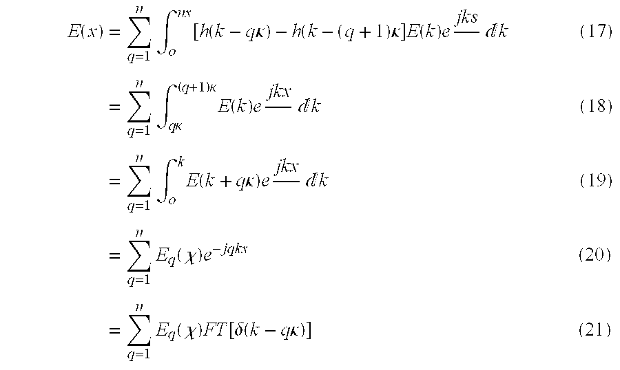
- E(k) of light emitted in any direction to a distance far from the object is proportional to the complex sum from all parts of the object of rays in that direction.
- This far-field distribution should be determined with the necessary angular resolution, approximately equal to the wavelength of light divided by the diameter of the object. It is well-known that the near-field distribution of light is then the spatial Fourier Transform of the far-field distribution 67 .
- E ⁇ ( x ) ⁇ o k ⁇ E ⁇ ( k ) ⁇ e ⁇ ⁇ jkx ⁇ ⁇ ⁇ x ( 15 )
- FT denotes the operation of taking a Fourier Transform
- E q (x) denotes the Fourier Transform of E(k+q ⁇ ) frequency shifted by q ⁇ .
- a lens focuses parallel rays of light so as to produce in its focal plane the distribution of complex amplitude which in the absence of the lens would be the far-field. The lens is therefore said to execute an optical Fourier transform on light travelling from one Fourier plane to the other.
- a spot source of light constitutes the function ⁇ (x), and if this is placed in the focal plane of a lens then parallel wavefronts will appear in the far focal plane with distribution FT[ ⁇ (k-qz)].
- a suitable liquid crystal display will modulate these wavefronts with the function E q (x), and time sequential addressing will sum the series, albeit as a summation of far-field intensifies rather than a sum of complex amplitudes as specified by the algebra. That the result is nevertheless a three dimensional image is because, as ever, the eye is insensitive to phase.
- the frame rate of the liquid crystal display must equal 50 n 0 Hz and the spatial periodicity must equal the reciprocal of ⁇ x, so the space-time periodicity must equal fifty times the field of view divided by the wavelength.
- the space-time periodicity should approximately equal 1 Mbit s ⁇ 1 : cm ⁇ 1 well above the 5 kbit s ⁇ 1 cm ⁇ 1 capabilities of large high resolution liquid crystal displays 66 .
- Hybridising the autostereoscopic and holographic pixellation schemes requires that there be coherence between adjacent pixels, and this is a fundamental property of displays with a single light source and bulk optics.
- the shuttered cathode ray tube system can also display hybrid pixellation images and it has already been noted that the system can screen data at higher rates than that based on liquid crystal displays.
- the two lenses in the shuttered cathode ray tube system can both be considered as effecting optical Fourier transforms 60 .
- Adopting a classical layout the cathode ray tube, should be in the rear focal plane of the rear lens, and the liquid crystal shutter in the focal plane shared by rear and front.
- liquid crystal displays lack the space-time periodicity needed for hybrid pixellation, one device stands out for its lack of complexity and high space-time periodicity: this is the light valve (also known as an optically addressable spatial light modulator).
- Section II notes that video holograms have already been screened by optically addressing such a device with a cathode ray tube but the field of view was narrow. With time multiplexed illumination it is possible to get a wider field of view and the frame rate of the latest light valves makes this possible 68 .
- FIG. 14 shows how the light valve can be addressed by multiplexing the image of an array across its rear, and high frame rate arrays now have the space bandwidth product needed to address light valves over large areas.
- a typical light valve can resolve down to 10 microns, which with a frame rate of 2 kHz gives a space-time periodicity of 2 ⁇ 10 15 m ⁇ 2 s ⁇ 1 .
- ⁇ 2 After dividing by 3 for colour and 60 for flicker, one can estimate the solid angle available for viewing by multiplying by ⁇ 2 , equal approximately to (0.5 ⁇ 10 ⁇ 6 ) 2 m 2 .
- the result is a solid angle of view of 0.025, equivalent to a viewing zone of say 30° in azimuth by 3° in elevation.
- An optical fibre is capable of transmitting data at such rates, and a simple method of scanning its output would be a tremendous prize both for displays and telecommunications.
- Acousto-optic holograms have a successful history but are limited by the speed of sound in acousto-optic materials which at 2 km/s restricts data rates to approximately 4 GHz for an optical wavelength of half a micron. In practice even these rates are difficult because of the melting problems mentioned in section II.
- Cathode ray tubes can be electrostatically scanned at megahertz line rates and providing the deflection angle is narrow and beam intensity not too high the spot size can be kept to a diameter of a few microns. But it is difficult to make such a small spot bright without defocusing, and a way must be found of modulating an electron gun at more than 1 GHz, so while these challenges are not insuperable they remain challenges.
- Laser diode arrays and the other arrays work by de-multiplexing the input to a sufficient resolution that raster scanning is either not required or need be no faster than can be executed by a liquid crystal hologram.
- An 18 ⁇ 1 laser diode array has been operated at 8 ⁇ 1 GHz, and 256 ⁇ 256 arrays have been fabricated offering the tantalising prospect of space bandwidth products far in excess of any alternative.
- Ferroelectric arrays are fast-switching liquid crystal displays where the active matrix transistors are etched in a silicon integrated circuit.
- a 320 ⁇ 240 array with a potential frame rate of 20 kHz has been demonstrated 70 , offering a space bandwidth product of 3.2 GHz. This is just about enough for a 16 cm wide screen, and it is demultiplexed enough for the array's image to be scanned across the light valve at the 20 kHz rates achievable by a one dimensional ferroelectric liquid crystal hologram. Deflection angles would be small (0.5 mm divided by say 20 cm from hologram to screen equalling 1/40 radian) so the resolution of the one dimensional hologram would be a wavelength divided by 1/40 radian, approximately equal to 20 microns.
- Micro-mirror array 71 have the advantage of being comprised entirely of silicon although they require a more intricate lithography. Nevertheless arrays of 2048 ⁇ 1152 pixels potentially offer a space bandwidth product of 5.8 GHz. Details of circuitry aside this offers the potential for a screen over 8 inches wide, and if three, such devices were operated in parallel (which is how they are configured for high definition 2D projection) then one could hope for better quality still. But once again optimistic conclusions are inappropriate, in this case because these devices merely convert data from an electronic form to an optical one: there is still required a source of data.
- Video three dimensional images can be pixellated in three ways: volumetric. holographic and autostereoscopic. While volumetric images use bandwidth efficiently to give all round viewing and holographic displays have high resolution, autostereoscopic displays image opaque objects with the wide fields of view needed for most applications.
- Holographic and time-multiplexed autostereoscopic pixellation schemes can be combined to give a hybrid which has the virtues of both.
- a sequentially illuminated holographic display has the same data content, resolution and depth as a hologram, but the field of view of an autostereoscopic display.
- all that is needed is a liquid crystal display with a space-time periodicity of the order of 1 Mbit s ⁇ 1 cm ⁇ 1 , but this is impractical over large areas at low cost.
- Light valves are simple enough to operate over screen-sized areas at low device cost and the arrays provide a way of spatially distributing data across the light valve which need not be expensive provided they are small. Projecting a small array onto a large light valve therefore gives a display which is cheap and has high resolution for the same reasons that the cathode ray tube does.
- the high frame rate array should be as close as possible to the electronics which decompress the three dimensional image in order to minimise high data rate connections.
- the computational power of the decompression electronics will be comparable to that of most computers, and it is not unlikely that the computer and display systems will therefore come to merge.
- FIG. 1 One can display a three dimensional image by showing views of the object on a liquid crystal display and illuminating each to an appropriate direction
- FIG. 2 Volumetric 3D displays
- FIG. 3 A three dimensional array of light emitters cannot display opaque images
- FIG. 4 Holographic 3D displays
- FIG. 5 Autostereoscopic 3D displays
- FIG. 6 A three dimensional object looks the same when seen through a pair of slits, one spinning rapidly, the other slowly.
- FIG. 7 Close to the screen a perspective image is seen whose composition can be determined by ray tracing.
- FIG. 8 A plot of pixel direction ( ⁇ ) versus pixel position (x) can be used to identify what the viewer sees on the display no matter how distant it is.
- FIG. 9 Distant photograph of an autostereoscopic display on which each view comprises a horizontal bar. Permission for Reprint, courtesy Society for Information Display.
- FIG. 10 Close-up photograph of an autostereoscopic display on which each view comprises a horizontal bar. Permission for Reprint, courtesy Society for Information Display.
- FIG. 11 An off-screen spot can be imaged by setting up rays to converge through it.
- FIG. 12 Two views of a cubic array are formed by parallel projection.
- the minimum angle ( ⁇ ) between the views required for there to be a distinct difference in view content is that required to make one column of rear pixels fully visible,
- FIG. 13 In the left hand video camera only the front pixels of the distorted cubic array are visible, while in the right hand camera one column of the rear pixels has become visible. As the depth of the distorted cubic array tends to infinity, RAY 1 and RAY 2 tend towards parallel, so the angle between adjacent views tends to the angle between adjacent pixels.
- FIG. 14 An autostereoscopic/holographic display with a wide field of view can be made by time-sequentially illuminating a high resolution liquid crystal display.
- a high resolution liquid crystal display can be assembled from a light valve and a high frame rate array.
- the angle per view ( ⁇ ) and depth (z) of the three pixellation schemes can be related by the width of the image (x), the depth of the image in pixels (n z ), the width of the image in pixels (n x ), the field of view of the image ( ⁇ ), the pixel size ( ⁇ x), and the wavelength ( ⁇ ).
Abstract
Description


| TABLE 1 | |||||
| Distorted | Cartesian | ||||
| volumetric | volumetric | Autostereo | Hologram | ||
| Angle per view |
 |
 |
 |
 |
| Depth | ∞ | z = ηzΔz |
 |
 |
Claims (11)
Applications Claiming Priority (3)
| Application Number | Priority Date | Filing Date | Title |
|---|---|---|---|
| GBGB9713658.4A GB9713658D0 (en) | 1997-06-28 | 1997-06-28 | View-sequential holographic display |
| GB9713658 | 1997-06-28 | ||
| PCT/GB1998/001866 WO1999000993A1 (en) | 1997-06-28 | 1998-06-26 | Autostereoscopic display |
Publications (1)
| Publication Number | Publication Date |
|---|---|
| US6831678B1 true US6831678B1 (en) | 2004-12-14 |
Family
ID=10815068
Family Applications (1)
| Application Number | Title | Priority Date | Filing Date |
|---|---|---|---|
| US09/446,007 Expired - Lifetime US6831678B1 (en) | 1997-06-28 | 1998-06-26 | Autostereoscopic display |
Country Status (8)
| Country | Link |
|---|---|
| US (1) | US6831678B1 (en) |
| EP (1) | EP0992163B1 (en) |
| JP (1) | JP4320410B2 (en) |
| KR (1) | KR100560529B1 (en) |
| CN (1) | CN1169379C (en) |
| DE (1) | DE69805073T2 (en) |
| GB (1) | GB9713658D0 (en) |
| WO (1) | WO1999000993A1 (en) |
Cited By (80)
| Publication number | Priority date | Publication date | Assignee | Title |
|---|---|---|---|---|
| US20030193485A1 (en) * | 2002-04-10 | 2003-10-16 | Da Cunha John M. | Active display system |
| US20030222977A1 (en) * | 2002-06-03 | 2003-12-04 | Kazutora Yoshino | Intelligent system and 3D virtual object generator |
| US20040155186A1 (en) * | 1998-08-05 | 2004-08-12 | Microvision, Inc. | Scanned beam display |
| US20040239757A1 (en) * | 2003-05-29 | 2004-12-02 | Alden Ray M. | Time sequenced user space segmentation for multiple program and 3D display |
| US20050099411A1 (en) * | 2003-11-12 | 2005-05-12 | Van Brocklin Andrew L. | Large area display and method of manufacturing same |
| US20050230641A1 (en) * | 2004-04-05 | 2005-10-20 | Won Chun | Data processing for three-dimensional displays |
| US20050280643A1 (en) * | 2004-06-16 | 2005-12-22 | Chuan-Sheng Chen | Graphic image to 3D image conversion device |
| US20060114214A1 (en) * | 2003-08-25 | 2006-06-01 | Dwight Griffin | Image rotation in display systems |
| US20060187530A1 (en) * | 2005-02-23 | 2006-08-24 | Pixtronix, Incorporated | Methods and apparatus for actuating displays |
| US20070064098A1 (en) * | 2005-09-19 | 2007-03-22 | Available For Licensing | Systems and methods for 3D rendering |
| US7269573B1 (en) * | 2000-07-13 | 2007-09-11 | Symbol Technologies, Inc. | Virtual-product presentation system |
| US20080086289A1 (en) * | 2006-10-06 | 2008-04-10 | 3M Innovative Properties Company | Method of designing a matched light guide for a stereoscopic 3d liquid crystal display |
| US20080204548A1 (en) * | 2006-10-27 | 2008-08-28 | Emine Goulanian | Switchable optical imaging system and related 3d/2d image switchable apparatus |
| US20080291268A1 (en) * | 2005-11-04 | 2008-11-27 | Koninklijke Philips Electronics, N.V. | Rendering of Image Data for Multi-View Display |
| US20080297593A1 (en) * | 2007-04-17 | 2008-12-04 | University Of Southern California | Rendering for an Interactive 360 Degree Light Field Display |
| US20090046143A1 (en) * | 2002-02-20 | 2009-02-19 | Martin Gerard Hendrik Hiddink | Autostereoscopic dislpay device |
| WO2009057114A2 (en) * | 2007-10-31 | 2009-05-07 | Ben Gurion University Of The Negev Research And Development Authority | Optical sensor measurement and crosstalk evaluation |
| US20090167846A1 (en) * | 2007-12-26 | 2009-07-02 | Nec Lcd Technologies | Image display device and terminal device |
| US20090190048A1 (en) * | 2007-11-02 | 2009-07-30 | Lg Display Co., Ltd. | Stereoscopic display device using electrically-driven liquid crystal lens |
| US20090251531A1 (en) * | 2008-04-04 | 2009-10-08 | Texas Instruments Incorporated | Coding scheme for digital video signals and an image architecture using the same |
| US7675665B2 (en) | 2005-02-23 | 2010-03-09 | Pixtronix, Incorporated | Methods and apparatus for actuating displays |
| US7742016B2 (en) | 2005-02-23 | 2010-06-22 | Pixtronix, Incorporated | Display methods and apparatus |
| US7746529B2 (en) | 2005-02-23 | 2010-06-29 | Pixtronix, Inc. | MEMS display apparatus |
| US7755582B2 (en) | 2005-02-23 | 2010-07-13 | Pixtronix, Incorporated | Display methods and apparatus |
| US20100202047A1 (en) * | 2007-07-13 | 2010-08-12 | Barco N.V. | Stereo display system with scanning of light valves |
| US20100207961A1 (en) * | 2007-07-23 | 2010-08-19 | Humaneyes Technologies Ltd. | Multi view displays and methods for producing the same |
| US20100259610A1 (en) * | 2009-04-08 | 2010-10-14 | Celsia, Llc | Two-Dimensional Display Synced with Real World Object Movement |
| US7839356B2 (en) | 2005-02-23 | 2010-11-23 | Pixtronix, Incorporated | Display methods and apparatus |
| US7852546B2 (en) | 2007-10-19 | 2010-12-14 | Pixtronix, Inc. | Spacers for maintaining display apparatus alignment |
| US7876489B2 (en) | 2006-06-05 | 2011-01-25 | Pixtronix, Inc. | Display apparatus with optical cavities |
| US7927654B2 (en) | 2005-02-23 | 2011-04-19 | Pixtronix, Inc. | Methods and apparatus for spatial light modulation |
| US20110096145A1 (en) * | 2006-05-23 | 2011-04-28 | See Real Technologies S.A. | Method and Device for Rendering and Generating Computer-Generated Video Holograms |
| US20110102422A1 (en) * | 2009-10-30 | 2011-05-05 | Samsung Electronics Co., Ltd. | Two-dimensional/three-dimensional image display apparatus and method of driving the same |
| US20110149153A1 (en) * | 2009-12-22 | 2011-06-23 | Electronics And Telecommunications Research Institute | Apparatus and method for dtv closed-captioning processing in broadcasting and communication system |
| US20110150276A1 (en) * | 2009-12-23 | 2011-06-23 | Searete Llc, A Limited Liability Corporation Of The State Of Delaware | Identifying a characteristic of an individual utilizing facial recognition and providing a display for the individual |
| US20110150299A1 (en) * | 2009-12-23 | 2011-06-23 | Searete Llc, A Limited Liability Corporation Of The State Of Delaware | Identifying a characteristic of an individual utilizing facial recognition and providing a display for the individual |
| US20110148753A1 (en) * | 2009-12-23 | 2011-06-23 | Searete Llc, A Limited Liability Corporation Of The State Of Delaware | Identifying a characteristic of an individual utilizing facial recognition and providing a display for the individual |
| US20110150297A1 (en) * | 2009-12-23 | 2011-06-23 | Searete Llc, A Limited Liability Corporation Of The State Of Delaware | Identifying a characteristic of an individual utilizing facial recognition and providing a display for the individual |
| US20110150298A1 (en) * | 2009-12-23 | 2011-06-23 | Searete Llc, A Limited Liability Corporation Of The State Of Delaware | Identifying a characteristic of an individual utilizing facial recognition and providing a display for the individual |
| US20110150296A1 (en) * | 2009-12-23 | 2011-06-23 | Searete Llc, A Limited Liability Corporation Of The State Of Delaware | Identifying a characteristic of an individual utilizing facial recognition and providing a display for the individual |
| US20110150294A1 (en) * | 2009-12-23 | 2011-06-23 | Searete Llc, A Limited Liability Corporation Of The State Of Delaware | Identifying a characteristic of an individual utilizing facial recognition and providing a display for the individual |
| US20110150295A1 (en) * | 2009-12-23 | 2011-06-23 | Searete Llc, A Limited Liability Corporation Of The State Of Delaware | Identifying a characteristic of an individual utilizing facial recognition and providing a display for the individual |
| US7978407B1 (en) | 2009-06-27 | 2011-07-12 | Holovisions LLC | Holovision (TM) 3D imaging with rotating light-emitting members |
| US20110206245A1 (en) * | 2009-12-23 | 2011-08-25 | Searete Llc, A Limited Liability Corporation Of The State Of Delaware | Identifying a characteristic of an individual utilizing facial recognition and providing a display for the individual |
| US20110211738A1 (en) * | 2009-12-23 | 2011-09-01 | Searete Llc, A Limited Liability Corporation Of The State Of Delaware | Identifying a characteristic of an individual utilizing facial recognition and providing a display for the individual |
| US20110211739A1 (en) * | 2009-12-23 | 2011-09-01 | Searete Llc, A Limited Liability Corporation Of The State Of Delaware | Identifying a characteristic of an individual utilizing facial recognition and providing a display for the individual |
| US20110228054A1 (en) * | 2010-03-17 | 2011-09-22 | Chunyu Gao | Methods To Eliminate/Reduce The Crosstalk Artifacts Of The Retro-Reflective Auto-Stereoscopic 3D Display |
| US20110310092A1 (en) * | 2010-05-21 | 2011-12-22 | Fraunhofer-Gesellschaft Zur Forderung Der Angewandten Forschung E.V. | Image display device and use thereof |
| US8091290B1 (en) | 2008-08-12 | 2012-01-10 | William Drakes | Geodesic entertainment sphere |
| US20120038634A1 (en) * | 2010-08-16 | 2012-02-16 | Hongrae Cha | Apparatus and method of displaying 3-dimensional image |
| US8159428B2 (en) | 2005-02-23 | 2012-04-17 | Pixtronix, Inc. | Display methods and apparatus |
| US20120113100A1 (en) * | 2010-09-15 | 2012-05-10 | Nlt Technologies, Ltd | Image display apparatus |
| US8248560B2 (en) | 2008-04-18 | 2012-08-21 | Pixtronix, Inc. | Light guides and backlight systems incorporating prismatic structures and light redirectors |
| US8262274B2 (en) | 2006-10-20 | 2012-09-11 | Pitronix, Inc. | Light guides and backlight systems incorporating light redirectors at varying densities |
| US8310442B2 (en) | 2005-02-23 | 2012-11-13 | Pixtronix, Inc. | Circuits for controlling display apparatus |
| US8482496B2 (en) | 2006-01-06 | 2013-07-09 | Pixtronix, Inc. | Circuits for controlling MEMS display apparatus on a transparent substrate |
| US8520285B2 (en) | 2008-08-04 | 2013-08-27 | Pixtronix, Inc. | Methods for manufacturing cold seal fluid-filled display apparatus |
| US8519945B2 (en) | 2006-01-06 | 2013-08-27 | Pixtronix, Inc. | Circuits for controlling display apparatus |
| US8526096B2 (en) | 2006-02-23 | 2013-09-03 | Pixtronix, Inc. | Mechanical light modulators with stressed beams |
| US8587498B2 (en) | 2010-03-01 | 2013-11-19 | Holovisions LLC | 3D image display with binocular disparity and motion parallax |
| US8599463B2 (en) | 2008-10-27 | 2013-12-03 | Pixtronix, Inc. | MEMS anchors |
| US20140293386A1 (en) * | 2013-03-29 | 2014-10-02 | Lg Display Co., Ltd. | Holographic Image Display Device and Method for Driving the Same |
| US20140300536A1 (en) * | 2013-04-09 | 2014-10-09 | Lg Display Co., Ltd. | Stereoscopic image display device and eye-tracking method thereof |
| US8860792B1 (en) | 2010-11-02 | 2014-10-14 | Tommy Lee Bolden | Two dimensional to three dimensional video display system |
| US20150172646A1 (en) * | 2013-12-17 | 2015-06-18 | Disney Enterprises, Inc. | Color display and projection system |
| US9082353B2 (en) | 2010-01-05 | 2015-07-14 | Pixtronix, Inc. | Circuits for controlling display apparatus |
| US9087486B2 (en) | 2005-02-23 | 2015-07-21 | Pixtronix, Inc. | Circuits for controlling display apparatus |
| US9135868B2 (en) | 2005-02-23 | 2015-09-15 | Pixtronix, Inc. | Direct-view MEMS display devices and methods for generating images thereon |
| US9134552B2 (en) | 2013-03-13 | 2015-09-15 | Pixtronix, Inc. | Display apparatus with narrow gap electrostatic actuators |
| US9176318B2 (en) | 2007-05-18 | 2015-11-03 | Pixtronix, Inc. | Methods for manufacturing fluid-filled MEMS displays |
| US9182605B2 (en) | 2014-01-29 | 2015-11-10 | Emine Goulanian | Front-projection autostereoscopic 3D display system |
| US9182606B2 (en) | 2014-01-29 | 2015-11-10 | Emine Goulanian | Rear-projection autostereoscopic 3D display system |
| US9229222B2 (en) | 2005-02-23 | 2016-01-05 | Pixtronix, Inc. | Alignment methods in fluid-filled MEMS displays |
| US9261694B2 (en) | 2005-02-23 | 2016-02-16 | Pixtronix, Inc. | Display apparatus and methods for manufacture thereof |
| US9500853B2 (en) | 2005-02-23 | 2016-11-22 | Snaptrack, Inc. | MEMS-based display apparatus |
| US9563269B2 (en) | 2014-03-25 | 2017-02-07 | Microsoft Technology Licensing, Llc | Scanning liquid-crystal display backlight |
| US20170285357A1 (en) * | 2016-03-30 | 2017-10-05 | Delta Electronics, Inc. | Multi-view display device |
| RU2702918C1 (en) * | 2018-12-20 | 2019-10-14 | Федеральное государственное бюджетное учреждение науки Физический институт им. П.Н. Лебедева Российской академии наук (ФИАН) | Glasses-free stereoscopic video system with liquid crystal remote binocular filter |
| US11100830B2 (en) * | 2020-01-13 | 2021-08-24 | Nvidia Corporation | Method and apparatus for spatiotemporal enhancement of patch scanning displays |
| US20220262064A1 (en) * | 2020-07-16 | 2022-08-18 | Tencent Technology (Shenzhen) Company Limited | Interaction method and apparatus, display device, and storage medium |
Families Citing this family (39)
| Publication number | Priority date | Publication date | Assignee | Title |
|---|---|---|---|---|
| GB0017312D0 (en) | 2000-07-15 | 2000-08-30 | Secr Defence | Bistable liquid crystal devices |
| DE10291111D2 (en) * | 2001-03-16 | 2004-04-15 | Candy Optronic Gmbh | Method and device for displaying picture elements in three-dimensional space |
| WO2002080579A2 (en) * | 2001-03-28 | 2002-10-10 | Dimensional Developments Aps | Self-aligning autostereoscopic 3d display |
| JP3519698B2 (en) * | 2001-04-20 | 2004-04-19 | 照明 與語 | 3D shape measurement method |
| JP3722028B2 (en) | 2001-07-05 | 2005-11-30 | ソニー株式会社 | Image reproduction device and image illumination device |
| KR100878217B1 (en) | 2001-08-28 | 2009-01-14 | 삼성전자주식회사 | Liquid crystal display device and method for driving thereof |
| GB2379351A (en) | 2001-09-04 | 2003-03-05 | Holographic Imaging Llc | Illuminating a computer generated hologram |
| US7839548B2 (en) | 2002-11-13 | 2010-11-23 | Seereal Technologies Gmbh | Video hologram and device for reconstructing video holograms |
| CN1325989C (en) * | 2003-05-13 | 2007-07-11 | 示创科技股份有限公司 | Liquid crystal projector with ferroelectric liquid crystal controller |
| JP4200056B2 (en) * | 2003-06-17 | 2008-12-24 | 有限会社シーフォン | Display device |
| GB2403864A (en) * | 2003-07-10 | 2005-01-12 | Ocuity Ltd | Pixel arrangement for an autostereoscopic display |
| US8619352B2 (en) | 2003-07-29 | 2013-12-31 | Silicon Quest Kabushiki-Kaisha | Projection display system using laser light source |
| GB0329012D0 (en) * | 2003-12-15 | 2004-01-14 | Univ Cambridge Tech | Hologram viewing device |
| DE102005021155B3 (en) * | 2005-04-29 | 2006-11-23 | Seereal Technologies Gmbh | Controllable lighting device |
| CN101263434B (en) * | 2005-09-15 | 2010-06-09 | 富士通株式会社 | Holograph recorder |
| CN1992914B (en) * | 2005-12-26 | 2010-12-29 | 财团法人工业技术研究院 | Automatic display device of stereoscopic image |
| WO2007119064A1 (en) | 2006-04-19 | 2007-10-25 | Setred As | High speed display shutter for autostereoscopic display |
| CN101356832B (en) * | 2006-05-04 | 2011-06-22 | 三星电子株式会社 | High resolution autostereoscopic display apparatus with interlaced image |
| DE102006024356B4 (en) * | 2006-05-19 | 2016-09-29 | Seereal Technologies S.A. | Holographic projection apparatus for reconstructing scenes and methods for holographic reconstruction |
| CN101558655A (en) * | 2006-11-29 | 2009-10-14 | F.珀斯扎特胡有限公司 | Three dimensional projection display |
| EP2115530A1 (en) | 2007-02-05 | 2009-11-11 | F. Poszat HU, L.L.C. | Holographic imaging systems |
| WO2009032339A1 (en) * | 2007-09-06 | 2009-03-12 | Olympus Corporation | Projection display system using laser light source |
| WO2009109785A2 (en) | 2008-03-07 | 2009-09-11 | Javid Khan | A three dimensional holographic volumetric display |
| US8284234B2 (en) | 2009-03-20 | 2012-10-09 | Absolute Imaging LLC | Endoscopic imaging using reflection holographic optical element for autostereoscopic 3-D viewing |
| CN101852982B (en) * | 2010-04-15 | 2012-05-23 | 万事利集团有限公司 | Manufacturing method of four-dimensional vivid photograph |
| EA018398B1 (en) * | 2010-10-28 | 2013-07-30 | Общество С Ограниченной Ответственностью "Мидивисана" | Method and apparatus producing three-dimentional image of an object |
| JP5953311B2 (en) * | 2010-11-08 | 2016-07-20 | シーリアル テクノロジーズ ソシエテ アノニムSeereal Technologies S.A. | Display device |
| CN102087831A (en) * | 2011-02-23 | 2011-06-08 | 南京大学 | LED (light-emitting diode) video device with ultra-high refresh rate for volumetric three-dimensional display |
| US8988474B2 (en) | 2011-07-18 | 2015-03-24 | Microsoft Technology Licensing, Llc | Wide field-of-view virtual image projector |
| CN102361497B (en) * | 2011-11-15 | 2013-10-23 | 南京大学 | Display method and display system for spatial three-dimensional video |
| US8950867B2 (en) * | 2011-11-23 | 2015-02-10 | Magic Leap, Inc. | Three dimensional virtual and augmented reality display system |
| US8754829B2 (en) * | 2012-08-04 | 2014-06-17 | Paul Lapstun | Scanning light field camera and display |
| US10025089B2 (en) | 2012-10-05 | 2018-07-17 | Microsoft Technology Licensing, Llc | Backlight for viewing three-dimensional images from a display from variable viewing angles |
| GB201513333D0 (en) | 2015-07-29 | 2015-09-09 | Khan Javid | Volumetric display |
| EP3537950A4 (en) | 2016-11-10 | 2019-10-30 | Magic Leap, Inc. | Method and system for eye tracking using speckle patterns |
| RU2686576C1 (en) | 2017-11-30 | 2019-04-29 | Самсунг Электроникс Ко., Лтд. | Holographic display compact device |
| TWI632540B (en) * | 2018-01-15 | 2018-08-11 | 友達光電股份有限公司 | Display apparatus and method of switching viewing angle thereof |
| CN108195305B (en) * | 2018-02-09 | 2020-03-31 | 京东方科技集团股份有限公司 | Binocular detection system and depth detection method thereof |
| EP3531213B1 (en) * | 2018-02-22 | 2022-11-16 | IMEC vzw | An optical device, a system and a method for forming a distribution of a three-dimensional light field |
Citations (6)
| Publication number | Priority date | Publication date | Assignee | Title |
|---|---|---|---|---|
| US5132839A (en) * | 1987-07-10 | 1992-07-21 | Travis Adrian R L | Three dimensional display device |
| US5483254A (en) * | 1993-12-28 | 1996-01-09 | Dimensional Displays Inc. | 3D video display devices |
| US5959664A (en) * | 1994-12-29 | 1999-09-28 | Sharp Kabushiki Kaisha | Observer tracking autostereoscopic display and method of tracking an observer |
| US6002458A (en) * | 1996-07-11 | 1999-12-14 | Seiko Epson Corporation | Liquid crystal display device |
| US6049367A (en) * | 1995-05-23 | 2000-04-11 | Colorlink, Inc. | Polarization manipulating device modulator with retarder stack which preconditions light for modulation and isotropic states |
| US6449090B1 (en) * | 1995-01-28 | 2002-09-10 | Sharp Kabushiki Kaisha | Three dimensional display viewable in both stereoscopic and autostereoscopic modes |
-
1997
- 1997-06-28 GB GBGB9713658.4A patent/GB9713658D0/en active Pending
-
1998
- 1998-06-26 JP JP50538199A patent/JP4320410B2/en not_active Expired - Lifetime
- 1998-06-26 CN CNB988086220A patent/CN1169379C/en not_active Expired - Lifetime
- 1998-06-26 DE DE69805073T patent/DE69805073T2/en not_active Expired - Lifetime
- 1998-06-26 EP EP98935109A patent/EP0992163B1/en not_active Expired - Lifetime
- 1998-06-26 KR KR1019997012407A patent/KR100560529B1/en not_active IP Right Cessation
- 1998-06-26 US US09/446,007 patent/US6831678B1/en not_active Expired - Lifetime
- 1998-06-26 WO PCT/GB1998/001866 patent/WO1999000993A1/en active IP Right Grant
Patent Citations (6)
| Publication number | Priority date | Publication date | Assignee | Title |
|---|---|---|---|---|
| US5132839A (en) * | 1987-07-10 | 1992-07-21 | Travis Adrian R L | Three dimensional display device |
| US5483254A (en) * | 1993-12-28 | 1996-01-09 | Dimensional Displays Inc. | 3D video display devices |
| US5959664A (en) * | 1994-12-29 | 1999-09-28 | Sharp Kabushiki Kaisha | Observer tracking autostereoscopic display and method of tracking an observer |
| US6449090B1 (en) * | 1995-01-28 | 2002-09-10 | Sharp Kabushiki Kaisha | Three dimensional display viewable in both stereoscopic and autostereoscopic modes |
| US6049367A (en) * | 1995-05-23 | 2000-04-11 | Colorlink, Inc. | Polarization manipulating device modulator with retarder stack which preconditions light for modulation and isotropic states |
| US6002458A (en) * | 1996-07-11 | 1999-12-14 | Seiko Epson Corporation | Liquid crystal display device |
Cited By (121)
| Publication number | Priority date | Publication date | Assignee | Title |
|---|---|---|---|---|
| US20040155186A1 (en) * | 1998-08-05 | 2004-08-12 | Microvision, Inc. | Scanned beam display |
| US7269573B1 (en) * | 2000-07-13 | 2007-09-11 | Symbol Technologies, Inc. | Virtual-product presentation system |
| US20090046143A1 (en) * | 2002-02-20 | 2009-02-19 | Martin Gerard Hendrik Hiddink | Autostereoscopic dislpay device |
| US20030193485A1 (en) * | 2002-04-10 | 2003-10-16 | Da Cunha John M. | Active display system |
| US20030222977A1 (en) * | 2002-06-03 | 2003-12-04 | Kazutora Yoshino | Intelligent system and 3D virtual object generator |
| US20040239757A1 (en) * | 2003-05-29 | 2004-12-02 | Alden Ray M. | Time sequenced user space segmentation for multiple program and 3D display |
| US20060114214A1 (en) * | 2003-08-25 | 2006-06-01 | Dwight Griffin | Image rotation in display systems |
| US20050099411A1 (en) * | 2003-11-12 | 2005-05-12 | Van Brocklin Andrew L. | Large area display and method of manufacturing same |
| US7286120B2 (en) * | 2003-11-12 | 2007-10-23 | Hewlett-Packard Development Company, L.P. | Large area display and method of manufacturing same |
| US7525541B2 (en) * | 2004-04-05 | 2009-04-28 | Actuality Systems, Inc. | Data processing for three-dimensional displays |
| US20050230641A1 (en) * | 2004-04-05 | 2005-10-20 | Won Chun | Data processing for three-dimensional displays |
| US20050280643A1 (en) * | 2004-06-16 | 2005-12-22 | Chuan-Sheng Chen | Graphic image to 3D image conversion device |
| US7349570B2 (en) * | 2004-06-16 | 2008-03-25 | Chuan-Sheng Chen | Graphic image to 3D image conversion device |
| US9229222B2 (en) | 2005-02-23 | 2016-01-05 | Pixtronix, Inc. | Alignment methods in fluid-filled MEMS displays |
| US9135868B2 (en) | 2005-02-23 | 2015-09-15 | Pixtronix, Inc. | Direct-view MEMS display devices and methods for generating images thereon |
| US20060187530A1 (en) * | 2005-02-23 | 2006-08-24 | Pixtronix, Incorporated | Methods and apparatus for actuating displays |
| US9500853B2 (en) | 2005-02-23 | 2016-11-22 | Snaptrack, Inc. | MEMS-based display apparatus |
| US8310442B2 (en) | 2005-02-23 | 2012-11-13 | Pixtronix, Inc. | Circuits for controlling display apparatus |
| US8519923B2 (en) | 2005-02-23 | 2013-08-27 | Pixtronix, Inc. | Display methods and apparatus |
| US9336732B2 (en) | 2005-02-23 | 2016-05-10 | Pixtronix, Inc. | Circuits for controlling display apparatus |
| US9274333B2 (en) | 2005-02-23 | 2016-03-01 | Pixtronix, Inc. | Alignment methods in fluid-filled MEMS displays |
| US9261694B2 (en) | 2005-02-23 | 2016-02-16 | Pixtronix, Inc. | Display apparatus and methods for manufacture thereof |
| US8159428B2 (en) | 2005-02-23 | 2012-04-17 | Pixtronix, Inc. | Display methods and apparatus |
| US7675665B2 (en) | 2005-02-23 | 2010-03-09 | Pixtronix, Incorporated | Methods and apparatus for actuating displays |
| US9177523B2 (en) | 2005-02-23 | 2015-11-03 | Pixtronix, Inc. | Circuits for controlling display apparatus |
| US7927654B2 (en) | 2005-02-23 | 2011-04-19 | Pixtronix, Inc. | Methods and apparatus for spatial light modulation |
| US7742016B2 (en) | 2005-02-23 | 2010-06-22 | Pixtronix, Incorporated | Display methods and apparatus |
| US7746529B2 (en) | 2005-02-23 | 2010-06-29 | Pixtronix, Inc. | MEMS display apparatus |
| US7755582B2 (en) | 2005-02-23 | 2010-07-13 | Pixtronix, Incorporated | Display methods and apparatus |
| US9158106B2 (en) | 2005-02-23 | 2015-10-13 | Pixtronix, Inc. | Display methods and apparatus |
| US9087486B2 (en) | 2005-02-23 | 2015-07-21 | Pixtronix, Inc. | Circuits for controlling display apparatus |
| US7839356B2 (en) | 2005-02-23 | 2010-11-23 | Pixtronix, Incorporated | Display methods and apparatus |
| US20070064098A1 (en) * | 2005-09-19 | 2007-03-22 | Available For Licensing | Systems and methods for 3D rendering |
| US9532038B2 (en) * | 2005-11-04 | 2016-12-27 | Koninklijke Philips N.V. | Rendering of image data for multi-view display |
| US20080291268A1 (en) * | 2005-11-04 | 2008-11-27 | Koninklijke Philips Electronics, N.V. | Rendering of Image Data for Multi-View Display |
| US8189039B2 (en) * | 2005-12-14 | 2012-05-29 | Koninklijke Philips Electronics N.V. | Autostereoscopic display device |
| US8519945B2 (en) | 2006-01-06 | 2013-08-27 | Pixtronix, Inc. | Circuits for controlling display apparatus |
| US8482496B2 (en) | 2006-01-06 | 2013-07-09 | Pixtronix, Inc. | Circuits for controlling MEMS display apparatus on a transparent substrate |
| US8526096B2 (en) | 2006-02-23 | 2013-09-03 | Pixtronix, Inc. | Mechanical light modulators with stressed beams |
| US9128277B2 (en) | 2006-02-23 | 2015-09-08 | Pixtronix, Inc. | Mechanical light modulators with stressed beams |
| US20110096145A1 (en) * | 2006-05-23 | 2011-04-28 | See Real Technologies S.A. | Method and Device for Rendering and Generating Computer-Generated Video Holograms |
| US7876489B2 (en) | 2006-06-05 | 2011-01-25 | Pixtronix, Inc. | Display apparatus with optical cavities |
| US7677733B2 (en) * | 2006-10-06 | 2010-03-16 | 3M Innovative Properties Company | Method of designing a matched light guide for a stereoscopic 3D liquid crystal display |
| US20080086289A1 (en) * | 2006-10-06 | 2008-04-10 | 3M Innovative Properties Company | Method of designing a matched light guide for a stereoscopic 3d liquid crystal display |
| US8262274B2 (en) | 2006-10-20 | 2012-09-11 | Pitronix, Inc. | Light guides and backlight systems incorporating light redirectors at varying densities |
| US8545084B2 (en) | 2006-10-20 | 2013-10-01 | Pixtronix, Inc. | Light guides and backlight systems incorporating light redirectors at varying densities |
| US8243127B2 (en) | 2006-10-27 | 2012-08-14 | Zecotek Display Systems Pte. Ltd. | Switchable optical imaging system and related 3D/2D image switchable apparatus |
| US20080204548A1 (en) * | 2006-10-27 | 2008-08-28 | Emine Goulanian | Switchable optical imaging system and related 3d/2d image switchable apparatus |
| US9055288B2 (en) | 2006-10-27 | 2015-06-09 | Zecotek Display Systems Ltd Pte | Switchable 3D/2D optical imaging system |
| US20080297593A1 (en) * | 2007-04-17 | 2008-12-04 | University Of Southern California | Rendering for an Interactive 360 Degree Light Field Display |
| US8432436B2 (en) * | 2007-04-17 | 2013-04-30 | University Of Southern California | Rendering for an interactive 360 degree light field display |
| US9176318B2 (en) | 2007-05-18 | 2015-11-03 | Pixtronix, Inc. | Methods for manufacturing fluid-filled MEMS displays |
| US8665518B2 (en) * | 2007-07-13 | 2014-03-04 | Barco N.V. | Stereo display system with scanning of light valves |
| US20100202047A1 (en) * | 2007-07-13 | 2010-08-12 | Barco N.V. | Stereo display system with scanning of light valves |
| US9035968B2 (en) * | 2007-07-23 | 2015-05-19 | Humaneyes Technologies Ltd. | Multi view displays and methods for producing the same |
| US20100207961A1 (en) * | 2007-07-23 | 2010-08-19 | Humaneyes Technologies Ltd. | Multi view displays and methods for producing the same |
| US7852546B2 (en) | 2007-10-19 | 2010-12-14 | Pixtronix, Inc. | Spacers for maintaining display apparatus alignment |
| WO2009057114A3 (en) * | 2007-10-31 | 2010-03-11 | Ben Gurion University Of The Negev Research And Development Authority | Optical sensor measurement and crosstalk evaluation |
| WO2009057114A2 (en) * | 2007-10-31 | 2009-05-07 | Ben Gurion University Of The Negev Research And Development Authority | Optical sensor measurement and crosstalk evaluation |
| US20110031418A1 (en) * | 2007-10-31 | 2011-02-10 | Ben Gurion Univesity of the Negev Research and Development Authority | Optical sensor measurement and crosstalk evaluation |
| US7855756B2 (en) * | 2007-11-02 | 2010-12-21 | Lg Display Co., Ltd. | Stereoscopic display device using electrically-driven liquid crystal lens |
| US20090190048A1 (en) * | 2007-11-02 | 2009-07-30 | Lg Display Co., Ltd. | Stereoscopic display device using electrically-driven liquid crystal lens |
| US8773517B2 (en) * | 2007-12-26 | 2014-07-08 | Nlt Technologies, Ltd. | Image display device and terminal device |
| US20090167846A1 (en) * | 2007-12-26 | 2009-07-02 | Nec Lcd Technologies | Image display device and terminal device |
| US8237779B2 (en) * | 2008-04-04 | 2012-08-07 | Texas Instruments Incorporated | Coding scheme for digital video signals and an image architecture using the same |
| US20090251531A1 (en) * | 2008-04-04 | 2009-10-08 | Texas Instruments Incorporated | Coding scheme for digital video signals and an image architecture using the same |
| US8441602B2 (en) | 2008-04-18 | 2013-05-14 | Pixtronix, Inc. | Light guides and backlight systems incorporating prismatic structures and light redirectors |
| US9243774B2 (en) | 2008-04-18 | 2016-01-26 | Pixtronix, Inc. | Light guides and backlight systems incorporating prismatic structures and light redirectors |
| US8248560B2 (en) | 2008-04-18 | 2012-08-21 | Pixtronix, Inc. | Light guides and backlight systems incorporating prismatic structures and light redirectors |
| US8520285B2 (en) | 2008-08-04 | 2013-08-27 | Pixtronix, Inc. | Methods for manufacturing cold seal fluid-filled display apparatus |
| US8891152B2 (en) | 2008-08-04 | 2014-11-18 | Pixtronix, Inc. | Methods for manufacturing cold seal fluid-filled display apparatus |
| US8091290B1 (en) | 2008-08-12 | 2012-01-10 | William Drakes | Geodesic entertainment sphere |
| US9116344B2 (en) | 2008-10-27 | 2015-08-25 | Pixtronix, Inc. | MEMS anchors |
| US8599463B2 (en) | 2008-10-27 | 2013-12-03 | Pixtronix, Inc. | MEMS anchors |
| US9182587B2 (en) | 2008-10-27 | 2015-11-10 | Pixtronix, Inc. | Manufacturing structure and process for compliant mechanisms |
| US20100259610A1 (en) * | 2009-04-08 | 2010-10-14 | Celsia, Llc | Two-Dimensional Display Synced with Real World Object Movement |
| US7978407B1 (en) | 2009-06-27 | 2011-07-12 | Holovisions LLC | Holovision (TM) 3D imaging with rotating light-emitting members |
| US20110102422A1 (en) * | 2009-10-30 | 2011-05-05 | Samsung Electronics Co., Ltd. | Two-dimensional/three-dimensional image display apparatus and method of driving the same |
| US20110149153A1 (en) * | 2009-12-22 | 2011-06-23 | Electronics And Telecommunications Research Institute | Apparatus and method for dtv closed-captioning processing in broadcasting and communication system |
| US20110150299A1 (en) * | 2009-12-23 | 2011-06-23 | Searete Llc, A Limited Liability Corporation Of The State Of Delaware | Identifying a characteristic of an individual utilizing facial recognition and providing a display for the individual |
| US20110148753A1 (en) * | 2009-12-23 | 2011-06-23 | Searete Llc, A Limited Liability Corporation Of The State Of Delaware | Identifying a characteristic of an individual utilizing facial recognition and providing a display for the individual |
| US9875719B2 (en) | 2009-12-23 | 2018-01-23 | Gearbox, Llc | Identifying a characteristic of an individual utilizing facial recognition and providing a display for the individual |
| US20110150295A1 (en) * | 2009-12-23 | 2011-06-23 | Searete Llc, A Limited Liability Corporation Of The State Of Delaware | Identifying a characteristic of an individual utilizing facial recognition and providing a display for the individual |
| US20110206245A1 (en) * | 2009-12-23 | 2011-08-25 | Searete Llc, A Limited Liability Corporation Of The State Of Delaware | Identifying a characteristic of an individual utilizing facial recognition and providing a display for the individual |
| US20110211738A1 (en) * | 2009-12-23 | 2011-09-01 | Searete Llc, A Limited Liability Corporation Of The State Of Delaware | Identifying a characteristic of an individual utilizing facial recognition and providing a display for the individual |
| US8712110B2 (en) | 2009-12-23 | 2014-04-29 | The Invention Science Fund I, LC | Identifying a characteristic of an individual utilizing facial recognition and providing a display for the individual |
| US20110150298A1 (en) * | 2009-12-23 | 2011-06-23 | Searete Llc, A Limited Liability Corporation Of The State Of Delaware | Identifying a characteristic of an individual utilizing facial recognition and providing a display for the individual |
| US20110150297A1 (en) * | 2009-12-23 | 2011-06-23 | Searete Llc, A Limited Liability Corporation Of The State Of Delaware | Identifying a characteristic of an individual utilizing facial recognition and providing a display for the individual |
| US20110211739A1 (en) * | 2009-12-23 | 2011-09-01 | Searete Llc, A Limited Liability Corporation Of The State Of Delaware | Identifying a characteristic of an individual utilizing facial recognition and providing a display for the individual |
| US20110150276A1 (en) * | 2009-12-23 | 2011-06-23 | Searete Llc, A Limited Liability Corporation Of The State Of Delaware | Identifying a characteristic of an individual utilizing facial recognition and providing a display for the individual |
| US20110150296A1 (en) * | 2009-12-23 | 2011-06-23 | Searete Llc, A Limited Liability Corporation Of The State Of Delaware | Identifying a characteristic of an individual utilizing facial recognition and providing a display for the individual |
| US20110150294A1 (en) * | 2009-12-23 | 2011-06-23 | Searete Llc, A Limited Liability Corporation Of The State Of Delaware | Identifying a characteristic of an individual utilizing facial recognition and providing a display for the individual |
| US9082353B2 (en) | 2010-01-05 | 2015-07-14 | Pixtronix, Inc. | Circuits for controlling display apparatus |
| US8587498B2 (en) | 2010-03-01 | 2013-11-19 | Holovisions LLC | 3D image display with binocular disparity and motion parallax |
| US8411135B2 (en) | 2010-03-17 | 2013-04-02 | Seiko Epson Corporation | Methods to eliminate/reduce the crosstalk artifacts of the retro-reflective auto-stereoscopic 3D display |
| US20110228054A1 (en) * | 2010-03-17 | 2011-09-22 | Chunyu Gao | Methods To Eliminate/Reduce The Crosstalk Artifacts Of The Retro-Reflective Auto-Stereoscopic 3D Display |
| US9319663B2 (en) * | 2010-05-21 | 2016-04-19 | Fraunhofer-Gesellschaft Zur Foerderung Der Angewandten Forschung E. V. | Image display using matrix screen and periodic grating having a fixed period |
| US20110310092A1 (en) * | 2010-05-21 | 2011-12-22 | Fraunhofer-Gesellschaft Zur Forderung Der Angewandten Forschung E.V. | Image display device and use thereof |
| US20120038634A1 (en) * | 2010-08-16 | 2012-02-16 | Hongrae Cha | Apparatus and method of displaying 3-dimensional image |
| US9030534B2 (en) * | 2010-08-16 | 2015-05-12 | Lg Electronics Inc. | Apparatus and method of displaying 3-dimensional image |
| US20120113100A1 (en) * | 2010-09-15 | 2012-05-10 | Nlt Technologies, Ltd | Image display apparatus |
| US8810567B2 (en) * | 2010-09-15 | 2014-08-19 | Nlt Technologies, Ltd. | Image display apparatus |
| US8860792B1 (en) | 2010-11-02 | 2014-10-14 | Tommy Lee Bolden | Two dimensional to three dimensional video display system |
| US9134552B2 (en) | 2013-03-13 | 2015-09-15 | Pixtronix, Inc. | Display apparatus with narrow gap electrostatic actuators |
| US9618903B2 (en) * | 2013-03-29 | 2017-04-11 | Lg Display Co., Ltd. | Holographic image display device and method for driving the same |
| US20140293386A1 (en) * | 2013-03-29 | 2014-10-02 | Lg Display Co., Ltd. | Holographic Image Display Device and Method for Driving the Same |
| US9883177B2 (en) * | 2013-04-09 | 2018-01-30 | Lg Display Co., Ltd. | Stereoscopic image display device and eye-tracking method thereof |
| US20140300536A1 (en) * | 2013-04-09 | 2014-10-09 | Lg Display Co., Ltd. | Stereoscopic image display device and eye-tracking method thereof |
| US20150172646A1 (en) * | 2013-12-17 | 2015-06-18 | Disney Enterprises, Inc. | Color display and projection system |
| US9693048B2 (en) * | 2013-12-17 | 2017-06-27 | Disney Enterprises, Inc. | Color display and projection system |
| US9182606B2 (en) | 2014-01-29 | 2015-11-10 | Emine Goulanian | Rear-projection autostereoscopic 3D display system |
| US9182605B2 (en) | 2014-01-29 | 2015-11-10 | Emine Goulanian | Front-projection autostereoscopic 3D display system |
| US9563269B2 (en) | 2014-03-25 | 2017-02-07 | Microsoft Technology Licensing, Llc | Scanning liquid-crystal display backlight |
| US20170285357A1 (en) * | 2016-03-30 | 2017-10-05 | Delta Electronics, Inc. | Multi-view display device |
| US9958691B2 (en) * | 2016-03-30 | 2018-05-01 | Delta Electronics, Inc. | Multi-view display device |
| RU2702918C1 (en) * | 2018-12-20 | 2019-10-14 | Федеральное государственное бюджетное учреждение науки Физический институт им. П.Н. Лебедева Российской академии наук (ФИАН) | Glasses-free stereoscopic video system with liquid crystal remote binocular filter |
| US11100830B2 (en) * | 2020-01-13 | 2021-08-24 | Nvidia Corporation | Method and apparatus for spatiotemporal enhancement of patch scanning displays |
| US20210350732A1 (en) * | 2020-01-13 | 2021-11-11 | Nvidia Corporation | Method and apparatus for spatiotemporal enhancement of patch scanning displays |
| US11663945B2 (en) * | 2020-01-13 | 2023-05-30 | Nvidia Corporation | Method and apparatus for spatiotemporal enhancement of patch scanning displays |
| US20220262064A1 (en) * | 2020-07-16 | 2022-08-18 | Tencent Technology (Shenzhen) Company Limited | Interaction method and apparatus, display device, and storage medium |
| US11948243B2 (en) * | 2020-07-16 | 2024-04-02 | Tencent Technology (Shenzhen) Company Limited | Three-dimensional virtual object interaction method and apparatus, display device, and storage medium |
Also Published As
| Publication number | Publication date |
|---|---|
| KR100560529B1 (en) | 2006-03-28 |
| CN1169379C (en) | 2004-09-29 |
| DE69805073D1 (en) | 2002-05-29 |
| WO1999000993A1 (en) | 1999-01-07 |
| JP4320410B2 (en) | 2009-08-26 |
| EP0992163B1 (en) | 2002-04-24 |
| JP2002506590A (en) | 2002-02-26 |
| GB9713658D0 (en) | 1997-09-03 |
| DE69805073T2 (en) | 2002-10-31 |
| KR20010014282A (en) | 2001-02-26 |
| EP0992163A1 (en) | 2000-04-12 |
| CN1269103A (en) | 2000-10-04 |
Similar Documents
| Publication | Publication Date | Title |
|---|---|---|
| US6831678B1 (en) | Autostereoscopic display | |
| Travis | The display of three-dimensional video images | |
| Benzie et al. | A survey of 3DTV displays: techniques and technologies | |
| Geng | Three-dimensional display technologies | |
| Son et al. | Methods for displaying three-dimensional images | |
| US6940653B2 (en) | Radiation conditioning system | |
| US6665108B2 (en) | System for the production of a dynamic image for display | |
| JP4576083B2 (en) | Holographic display | |
| US6665100B1 (en) | Autostereoscopic three dimensional display using holographic projection | |
| US7924484B2 (en) | Video hologram and device for reconstructing video holograms with small region encoding | |
| US8075138B2 (en) | System and methods for angular slice true 3-D display | |
| Bove | Display holography's digital second act | |
| US20070242237A1 (en) | System and Methods for Angular Slice True 3-D Display | |
| KR101539668B1 (en) | 3 3-dimensional image display device and method using a hologram optical element | |
| Chen et al. | Coarse integral holography approach for real 3D color video displays | |
| JPH1039255A (en) | Three-dimensional image projecting device | |
| Bove Jr | Holographic television | |
| WO2002033494A2 (en) | Holographic stereogram printing apparatus and a method therefor | |
| Hopper | Reality and surreality of 3-D displays: holodeck and beyond | |
| JP2004272000A (en) | Hologram animation image display system | |
| KR100311910B1 (en) | Stereo movie recording / playback device using volume holographic memory | |
| JP2007221434A (en) | Image reproducing device | |
| Chatterjee et al. | Autostereoscopic, partial pixel, spatially multiplexed, and other 3D display technologies | |
| Schulze | Synthesis of moving holographic stereograms with high-resolution spatial light modulators | |
| Byoungho Lee et al. | THREE-DIMENSIONAL DISPLAY AND INFORMATION PROCESSING BASED ON INTEGRAL IMAGING |
Legal Events
| Date | Code | Title | Description |
|---|---|---|---|
| AS | Assignment |
Owner name: SECRETARY OF STATE FOR DEFENCE, THE, GREAT BRITAIN Free format text: ASSIGNMENT OF ASSIGNORS INTEREST;ASSIGNOR:TRAVIS, ADRIAN R L;REEL/FRAME:010825/0820 Effective date: 19991202 |
|
| AS | Assignment |
Owner name: HOLOGRAPHIC IMAGING LLC, MICHIGAN Free format text: ASSIGNMENT OF ASSIGNORS INTEREST;ASSIGNOR:SECRETARY OF STATE FOR DEFENSE, THE;REEL/FRAME:013661/0169 Effective date: 20001208 |
|
| STCF | Information on status: patent grant |
Free format text: PATENTED CASE |
|
| AS | Assignment |
Owner name: QINETIQ LIMITED, UNITED KINGDOM Free format text: ASSIGNMENT OF ASSIGNORS INTEREST;ASSIGNOR:HOLOGRAPHIC IMAGING LLC;REEL/FRAME:017366/0295 Effective date: 20051212 |
|
| AS | Assignment |
Owner name: F. POSZAT HU, LLC, DELAWARE Free format text: ASSIGNMENT OF ASSIGNORS INTEREST;ASSIGNOR:QINETIQ LIMITED COMPANY;REEL/FRAME:019140/0578 Effective date: 20070327 |
|
| FPAY | Fee payment |
Year of fee payment: 4 |
|
| FPAY | Fee payment |
Year of fee payment: 8 |
|
| FPAY | Fee payment |
Year of fee payment: 12 |
|
| AS | Assignment |
Owner name: HANGER SOLUTIONS, LLC, GEORGIA Free format text: ASSIGNMENT OF ASSIGNORS INTEREST;ASSIGNOR:INTELLECTUAL VENTURES ASSETS 161 LLC;REEL/FRAME:052159/0509 Effective date: 20191206 |
|
| AS | Assignment |
Owner name: INTELLECTUAL VENTURES ASSETS 161 LLC, DELAWARE Free format text: ASSIGNMENT OF ASSIGNORS INTEREST;ASSIGNOR:F. POSZAT HU, L.L.C.;REEL/FRAME:051944/0432 Effective date: 20191126 |