US6697147B2 - Position measurement apparatus and method using laser - Google Patents
Position measurement apparatus and method using laser Download PDFInfo
- Publication number
- US6697147B2 US6697147B2 US10/289,300 US28930002A US6697147B2 US 6697147 B2 US6697147 B2 US 6697147B2 US 28930002 A US28930002 A US 28930002A US 6697147 B2 US6697147 B2 US 6697147B2
- Authority
- US
- United States
- Prior art keywords
- target
- picture
- points
- position measurement
- laser
- Prior art date
- Legal status (The legal status is an assumption and is not a legal conclusion. Google has not performed a legal analysis and makes no representation as to the accuracy of the status listed.)
- Expired - Lifetime
Links
Images


Classifications
-
- G—PHYSICS
- G01—MEASURING; TESTING
- G01C—MEASURING DISTANCES, LEVELS OR BEARINGS; SURVEYING; NAVIGATION; GYROSCOPIC INSTRUMENTS; PHOTOGRAMMETRY OR VIDEOGRAMMETRY
- G01C3/00—Measuring distances in line of sight; Optical rangefinders
-
- G—PHYSICS
- G01—MEASURING; TESTING
- G01C—MEASURING DISTANCES, LEVELS OR BEARINGS; SURVEYING; NAVIGATION; GYROSCOPIC INSTRUMENTS; PHOTOGRAMMETRY OR VIDEOGRAMMETRY
- G01C3/00—Measuring distances in line of sight; Optical rangefinders
- G01C3/02—Details
- G01C3/06—Use of electric means to obtain final indication
- G01C3/08—Use of electric radiation detectors
Definitions
- the present invention relates generally to position measurement, and more particularly to the position measurement of a mobile object relative to a surrounding structure.
- the supersonic wave distance measurement apparatus uses an electromagnetic induction phenomenon or a piezoelectric phenomenon, and includes a wave transmitter and a wave receiver. If the wave transmitter emits supersonic waves, the wave receiver receives the supersonic waves that collide with a target to be measured and are reflected therefrom. In this case, a distance between the target and a mobile object is measured using a velocity of the supersonic waves, and a time taken to receive the supersonic waves from emission. The time taken to receive the supersonic waves from the emission is measured using a flip-flop.
- the flip-flop is set when the wave transmitter emits the supersonic waves, and is reset when the wave receiver detects the reflected supersonic waves, a pulse having a width of time for supersonic waves to be returned after being emitted is generated. By measuring this pulse, the time is obtained.
- the accuracy of the supersonic wave distance measurement apparatus is greatly decreased due to a diffused reflection at a bending surface.
- the supersonic wave distance measurement apparatus is problematic in that it is weak in a noisy environment, and real time measurement of precise distances is difficult.
- the laser distance measurement apparatuses are classified into various types, which use phase variation of reflection waves, pulses, and received light from reflection waves by triangulation.
- the type using the pulses emits a single pulse or a series of pulses, which are coherent light, toward a target. These pulses are scarcely dispersed to such an extent that a diameter of the pulses expands to only about 1 m after the light travels a distance of several kilometers. Once the light reaches the target, it is dispersed in many directions. However, some energy is returned to the laser distance measurement apparatus and detected.
- the laser distance measurement apparatus determines a distance between a mobile object and the target by measuring a time taken for the pulses to be reflected and returned.
- the laser distance measurement type using triangulation is an apparatus that emits laser beams, detects light reflected from a target with a laser light receiving sensor, detects a laser emission angle, and measures a distance between a mobile object and the target via triangulation.
- the laser distance measurement type using the triangulation is problematic in that a laser output must be great, a sensitivity of the light receiving sensor must be excellent, and a circuit construction of the light receiving sensor is extremely complicated, thus increasing cost of products.
- the type using the triangulation is problematic in that it requires extreme caution in handling of the laser distance measurement apparatus, thus it is not practical.
- a position measurement apparatus using laser including a laser generating device to generate three or more laser beams progressing in parallel with each other at regular intervals, an image device to obtain a picture for three or more points formed on a target by the laser beams, and a control unit to calculate a position relative to the target using numbers of pixels between pairs of neighboring ones of the three or more points in the picture.
- a method including generating three or more laser beams progressing in parallel with each other at regular intervals, obtaining a picture for three or more points formed on a target by the laser beams, and calculating an angle between each of the laser beams and the target, and a distance between an image device to obtain the picture and the target using numbers of pixels between pairs of neighboring ones of the three or more points in the picture.
- FIG. 1A is a plan view of a position measurement apparatus using laser, according to an embodiment of the present invention.
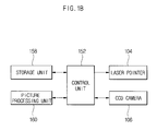
- FIG. 1B is a block diagram of the position measurement apparatus using laser according to the present invention.
- FIG. 2A is a view showing a concept of angle measurement of the position measurement apparatus using laser according to the present invention.
- FIGS. 2B and 2C are views showing pictures obtained to measure an angle in the position measurement apparatus using laser according to the present invention.
- FIG. 3A is a view showing a concept of distance measurement of the position measurement apparatus using laser according to the present invention.
- FIGS. 3B and 3C are views showing pictures obtained to measure a distance in the position measurement apparatus using laser according to the present invention.
- FIG. 4 is a flowchart of a position measurement method performed by the position measurement apparatus using laser according to the present invention.
- FIG. 5 is a view showing an example of a mobile robot employing the position measurement apparatus using laser according to the present invention.
- FIG. 1A is a plan view of a position measurement apparatus using a laser, according to an embodiment of the present invention.
- a laser position measurement apparatus 102 of the present invention includes three laser pointers 104 , and a charged coupled device (CCD) camera 106 .
- the three laser pointers 104 are installed at regular intervals, and generate three laser beams parallel with each other.
- the CCD camera 106 obtains a picture by photographing three points formed by the three laser beams on a surface (not shown).
- the CCD camera 106 is installed such that a point formed by a center one of the three laser pointers 104 is displayed at a center position on a screen (not shown).
- a resolution of the CCD camera 106 is one of many factors used to precisely measure angle and distance. According to the present invention, the resolution of the CCD camera 106 is selected according to required precision.
- FIG. 1B is a block diagram of the position measurement apparatus using the laser according to the present invention.
- a control unit 152 controls the laser pointers 104 to generate the laser beams, and controls the CCD camera 106 to obtain the picture of the points formed by the laser beams on the surface (not shown).
- Data of the picture obtained by the CCD camera 106 are stored in a storage unit 158 and used when the control unit 152 calculates the angle and the distance.
- a picture processing unit 160 extracts only position information of the points formed by the laser beams from the picture by filtering the picture obtained by the CCD camera 106 .
- FIG. 2A is a view showing a concept of angle measurement of the position measurement apparatus using laser according to the present invention.
- the angle between each of the laser beams generated by the position measurement apparatus 102 and a normal of a wall surface 108 is ⁇
- ⁇ the angle between each of the laser beams generated by the position measurement apparatus 102 and a normal of a wall surface 108
- FIGS. 2B and 2C are views showing pictures obtained to measure an angle in the position measurement apparatus using laser according to the present invention.
- a picture is obtained by the CCD camera 106 where ⁇ 0.
- the three laser beams are not perpendicular to the wall surface 108 , distances between pairs of neighboring ones of the three points generated by the laser beams are not the same. That is, on the basis of a center point, a left point is closer to the center point than a right point.
- the picture of FIG. 2B shows that distance a′ is longer than distance a′′.
- the distances a′ and a′′ are values obtained using numbers of pixels in the picture.
- FIG. 3 A is a view showing a concept of distance measurement of the position measurement apparatus using laser according to the present invention.
- an actual distance L between the wall surface 108 and the CCD camera 106 is obtained by emitting the laser beams perpendicularly to the wall surface 108 , and calculating distances between pairs of neighboring ones of three points in the picture obtained by the CCD camera 106 .
- a principle of distance measurement of the above-described position measurement apparatus of the present invention is described with reference to FIGS. 3B and 3C.
- FIGS. 3B and 3C are views showing pictures obtained to measure a distance in the position measurement apparatus using laser according to the present invention.
- FIG. 3B shows a short distance picture
- FIG. 3C shows a long distance picture.
- a distance a′ in the short distance picture of FIG. 3B is longer than the distance a′ in the long distance picture of FIG. 3 C.
- the distance a′ is obtained using the number of pixels of the picture.
- an actual distance between the CCD camera 106 and the wall surface 108 is obtained by the following Equation (1) if an actual distance per unit pixel is known.
- L k ⁇ 1 x - b ( 1 )
- Equation (1) L is the distance between the CCD camera 106 and the wall surface 108 , x is a sum of a′+a′′ of distances between pairs of neighboring points in the picture (or a sum of the numbers of pixels between pairs of neighboring points in the picture), and k and b are constants.
- the constants k and b are values obtained from data based on two or more experiments taken to calculate the actual distance per unit pixel.
- the distance L between the wall surface 108 and the CCD camera 106 is in inverse proportion to the sum a′+a′′ of distances between pairs of neighboring ones of the three points in the picture. That is, as the number of pixels corresponding to the distance a′ in the picture is small, the distance L between the CCD camera 106 and the wall surface 108 is greater. On the contrary, as the number of pixels corresponding to the distance a′ in the picture is large, the distance L between the CCD camera 106 and the wall surface 108 is shorter.
- FIG. 4 is a flowchart of a position measurement method performed by the position measurement apparatus using laser according to the present invention.
- the laser pointers 104 are turned on to generate the laser beams at operation S 402 .
- the picture for three pointers formed on the wall surface 108 by the CCD camera 106 is obtained at operation S 404 .
- the obtained picture is filtered, such that only position information of the three laser points is extracted at operation S 406 .
- the numbers of pixels between pairs of neighboring ones of the three points are detected at operation S 408 , and respective distances a′ and a′′ between neighboring points are compared at operation S 410 .
- FIG. 5 is a view showing an example of a mobile robot employing the position measurement apparatus using laser according to the present invention.
- the laser pointers 104 and the CCD camera 106 are mounted on a mobile robot 500 , and a relative position of the mobile robot 500 to the wall surface 108 is measured, thus enabling position control of a mobile robot in home or industry applications.
- a similar use can be adapted for other applications, such as collision avoidance systems in vehicles (such as automobiles).
- the present invention provides a position measurement apparatus and method using laser, which obtains a relative position of a mobile object to a target by measuring its relative angle and distance to the target, such as, for example, a wall surface.
- the present invention uses laser pointers and a CCD camera which have simple constructions and low prices, so that the position measurement apparatus is handled conveniently and is economical.
- the present invention is advantageous in that, since its position measurement algorithm is simple, the load of an entire position measurement system is reduced. Also, since a position measurement time is shortened due to the reduction of load, position measurement may be performed in real time. Also, the present invention is advantageous in that, since it ascertains positions of points by filtering a picture obtained by photographing laser points, position measurement may be performed at night. Additionally, while disclosed as being parallel, it is understood that the lasers adjacent to a central laser need not be parallel to the central laser but may be angled at roughly equal angels, so that the rotation and actual distance operations are equivalently performed
Abstract
Description

Claims (17)


Applications Claiming Priority (2)
| Application Number | Priority Date | Filing Date | Title |
|---|---|---|---|
| KR2002-37604 | 2002-06-29 | ||
| KR1020020037604A KR100556612B1 (en) | 2002-06-29 | 2002-06-29 | Apparatus and method of localization using laser |
Publications (2)
| Publication Number | Publication Date |
|---|---|
| US20040001197A1 US20040001197A1 (en) | 2004-01-01 |
| US6697147B2 true US6697147B2 (en) | 2004-02-24 |
Family
ID=29774998
Family Applications (1)
| Application Number | Title | Priority Date | Filing Date |
|---|---|---|---|
| US10/289,300 Expired - Lifetime US6697147B2 (en) | 2002-06-29 | 2002-11-07 | Position measurement apparatus and method using laser |
Country Status (4)
| Country | Link |
|---|---|
| US (1) | US6697147B2 (en) |
| JP (1) | JP3659957B2 (en) |
| KR (1) | KR100556612B1 (en) |
| CN (1) | CN1302290C (en) |
Cited By (68)
| Publication number | Priority date | Publication date | Assignee | Title |
|---|---|---|---|---|
| US20020153184A1 (en) * | 2001-04-18 | 2002-10-24 | Jeong-Gon Song | Robot cleaner, robot cleaning system and method for controlling same |
| US6995762B1 (en) * | 2001-09-13 | 2006-02-07 | Symbol Technologies, Inc. | Measurement of dimensions of solid objects from two-dimensional image(s) |
| US20060167608A1 (en) * | 2003-07-03 | 2006-07-27 | Hannu Makela | Arrangement for monitoring the location of a mining vehicle in a mine |
| US20060190133A1 (en) * | 2005-02-18 | 2006-08-24 | Irobot Corporation | Autonomous surface cleaning robot for wet cleaning |
| US20060290781A1 (en) * | 2005-06-28 | 2006-12-28 | Fujitsu Limited | Image obtaining apparatus |
| US7211980B1 (en) | 2006-07-05 | 2007-05-01 | Battelle Energy Alliance, Llc | Robotic follow system and method |
| US20070114975A1 (en) * | 2004-01-21 | 2007-05-24 | Irobot Corporation | Autonomous robot auto-docking and energy management systems and methods |
| CN100352624C (en) * | 2004-07-27 | 2007-12-05 | 朱兴龙 | Multifreedom stereo vision device having laser |
| US20080009964A1 (en) * | 2006-07-05 | 2008-01-10 | Battelle Energy Alliance, Llc | Robotics Virtual Rail System and Method |
| US20080009968A1 (en) * | 2006-07-05 | 2008-01-10 | Battelle Energy Alliance, Llc | Generic robot architecture |
| US20080009966A1 (en) * | 2006-07-05 | 2008-01-10 | Battelle Energy Alliance, Llc | Occupancy Change Detection System and Method |
| US20080009967A1 (en) * | 2006-07-05 | 2008-01-10 | Battelle Energy Alliance, Llc | Robotic Intelligence Kernel |
| US20080009965A1 (en) * | 2006-07-05 | 2008-01-10 | Battelle Energy Alliance, Llc | Autonomous Navigation System and Method |
| US20080009970A1 (en) * | 2006-07-05 | 2008-01-10 | Battelle Energy Alliance, Llc | Robotic Guarded Motion System and Method |
| US7383152B1 (en) | 2006-01-10 | 2008-06-03 | Alliant Techsystems Inc. | Non-contact deviation measurement system |
| US20080140255A1 (en) * | 2005-02-18 | 2008-06-12 | Irobot Corporation | Autonomous surface cleaning robot for wet and dry cleaning |
| US20080282494A1 (en) * | 2005-12-02 | 2008-11-20 | Irobot Corporation | Modular robot |
| US20090122360A1 (en) * | 2007-11-14 | 2009-05-14 | Yasuyuki Tanaka | Reading apparatus, image forming apparatus and image forming method |
| US20090325456A1 (en) * | 2008-05-22 | 2009-12-31 | William Willett | Play sets |
| US20100049365A1 (en) * | 2001-06-12 | 2010-02-25 | Irobot Corporation | Method and System for Multi-Mode Coverage For An Autonomous Robot |
| US7706917B1 (en) | 2004-07-07 | 2010-04-27 | Irobot Corporation | Celestial navigation system for an autonomous robot |
| US7796782B1 (en) * | 2005-09-19 | 2010-09-14 | Manouchehr Motamedi | Remote distance-measurement between any two arbitrary points using laser assisted optics |
| US20110054689A1 (en) * | 2009-09-03 | 2011-03-03 | Battelle Energy Alliance, Llc | Robots, systems, and methods for hazard evaluation and visualization |
| US20110077802A1 (en) * | 2005-12-02 | 2011-03-31 | Halloran Michael J | Robot System |
| US20110131741A1 (en) * | 2002-01-03 | 2011-06-09 | Jones Joseph L | Autonomous Floor-Cleaning Robot |
| US20110242402A1 (en) * | 2005-05-11 | 2011-10-06 | Wernersson Mats Goeran Henry | Digital cameras with triangulation autofocus system |
| US20110273722A1 (en) * | 2007-09-26 | 2011-11-10 | Elbit Systems Ltd | Wide field of view optical tracking system |
| US8073564B2 (en) | 2006-07-05 | 2011-12-06 | Battelle Energy Alliance, Llc | Multi-robot control interface |
| CN102313525A (en) * | 2011-07-26 | 2012-01-11 | 武汉武大卓越科技有限责任公司 | Laser beam parallelism regulating system and regulating method thereof |
| US8239992B2 (en) | 2007-05-09 | 2012-08-14 | Irobot Corporation | Compact autonomous coverage robot |
| US8253368B2 (en) | 2004-01-28 | 2012-08-28 | Irobot Corporation | Debris sensor for cleaning apparatus |
| US20120232697A1 (en) * | 2009-11-17 | 2012-09-13 | Lee Jeihun | Robot cleaner and controlling method thereof |
| US8271132B2 (en) | 2008-03-13 | 2012-09-18 | Battelle Energy Alliance, Llc | System and method for seamless task-directed autonomy for robots |
| US20130027548A1 (en) * | 2011-07-28 | 2013-01-31 | Apple Inc. | Depth perception device and system |
| US8368339B2 (en) | 2001-01-24 | 2013-02-05 | Irobot Corporation | Robot confinement |
| US8380350B2 (en) | 2005-12-02 | 2013-02-19 | Irobot Corporation | Autonomous coverage robot navigation system |
| US8386081B2 (en) | 2002-09-13 | 2013-02-26 | Irobot Corporation | Navigational control system for a robotic device |
| US8396592B2 (en) | 2001-06-12 | 2013-03-12 | Irobot Corporation | Method and system for multi-mode coverage for an autonomous robot |
| US8412377B2 (en) | 2000-01-24 | 2013-04-02 | Irobot Corporation | Obstacle following sensor scheme for a mobile robot |
| US8417383B2 (en) | 2006-05-31 | 2013-04-09 | Irobot Corporation | Detecting robot stasis |
| US8418303B2 (en) | 2006-05-19 | 2013-04-16 | Irobot Corporation | Cleaning robot roller processing |
| US8428778B2 (en) | 2002-09-13 | 2013-04-23 | Irobot Corporation | Navigational control system for a robotic device |
| KR101255194B1 (en) * | 2011-03-28 | 2013-04-23 | 강정수 | Distance measuring method and device |
| US20130204483A1 (en) * | 2012-02-04 | 2013-08-08 | Chulmo Sung | Robot cleaner |
| US8515578B2 (en) | 2002-09-13 | 2013-08-20 | Irobot Corporation | Navigational control system for a robotic device |
| US8600553B2 (en) | 2005-12-02 | 2013-12-03 | Irobot Corporation | Coverage robot mobility |
| US8739355B2 (en) | 2005-02-18 | 2014-06-03 | Irobot Corporation | Autonomous surface cleaning robot for dry cleaning |
| US8788092B2 (en) | 2000-01-24 | 2014-07-22 | Irobot Corporation | Obstacle following sensor scheme for a mobile robot |
| US8800107B2 (en) | 2010-02-16 | 2014-08-12 | Irobot Corporation | Vacuum brush |
| US8885177B2 (en) | 2007-09-26 | 2014-11-11 | Elbit Systems Ltd. | Medical wide field of view optical tracking system |
| US8930023B2 (en) | 2009-11-06 | 2015-01-06 | Irobot Corporation | Localization by learning of wave-signal distributions |
| US8965578B2 (en) | 2006-07-05 | 2015-02-24 | Battelle Energy Alliance, Llc | Real time explosive hazard information sensing, processing, and communication for autonomous operation |
| US8972052B2 (en) | 2004-07-07 | 2015-03-03 | Irobot Corporation | Celestial navigation system for an autonomous vehicle |
| US9008835B2 (en) | 2004-06-24 | 2015-04-14 | Irobot Corporation | Remote control scheduler and method for autonomous robotic device |
| CN105445745A (en) * | 2015-12-04 | 2016-03-30 | 同方威视技术股份有限公司 | Mobile target state monitoring method and apparatus, and vehicle rapid inspection system thereof |
| US9320398B2 (en) | 2005-12-02 | 2016-04-26 | Irobot Corporation | Autonomous coverage robots |
| US10094662B1 (en) | 2017-03-28 | 2018-10-09 | Trimble Inc. | Three-dimension position and heading solution |
| EP3454006A1 (en) | 2017-09-12 | 2019-03-13 | Fundació Institut de Ciències Fotòniques | A method, a system and a computer program for measuring a distance to a target |
| US10300573B2 (en) | 2017-05-24 | 2019-05-28 | Trimble Inc. | Measurement, layout, marking, firestop stick |
| US10341618B2 (en) | 2017-05-24 | 2019-07-02 | Trimble Inc. | Infrastructure positioning camera system |
| US10339670B2 (en) | 2017-08-29 | 2019-07-02 | Trimble Inc. | 3D tool tracking and positioning using cameras |
| US10347008B2 (en) | 2017-08-14 | 2019-07-09 | Trimble Inc. | Self positioning camera system to 3D CAD/BIM model |
| US10406645B2 (en) | 2017-05-24 | 2019-09-10 | Trimble Inc. | Calibration approach for camera placement |
| US10739439B2 (en) | 2018-05-04 | 2020-08-11 | Industrial Technology Research Institute | Laser positioning system and position measuring method using the same |
| US10997747B2 (en) | 2019-05-09 | 2021-05-04 | Trimble Inc. | Target positioning with bundle adjustment |
| US11002541B2 (en) | 2019-07-23 | 2021-05-11 | Trimble Inc. | Target positioning with electronic distance measuring and bundle adjustment |
| US11255663B2 (en) | 2016-03-04 | 2022-02-22 | May Patents Ltd. | Method and apparatus for cooperative usage of multiple distance meters |
| US11644571B2 (en) | 2019-07-01 | 2023-05-09 | Samsung Electronics Co., Ltd. | Electronic apparatus and control method thereof |
Families Citing this family (79)
| Publication number | Priority date | Publication date | Assignee | Title |
|---|---|---|---|---|
| US20040162637A1 (en) | 2002-07-25 | 2004-08-19 | Yulun Wang | Medical tele-robotic system with a master remote station with an arbitrator |
| US7813836B2 (en) | 2003-12-09 | 2010-10-12 | Intouch Technologies, Inc. | Protocol for a remotely controlled videoconferencing robot |
| EP1571584A1 (en) * | 2004-03-03 | 2005-09-07 | Honda Research Institute Europe GmbH | Integrating visual and object information in a pervasive computing environment |
| US8077963B2 (en) | 2004-07-13 | 2011-12-13 | Yulun Wang | Mobile robot with a head-based movement mapping scheme |
| US7164118B2 (en) * | 2004-10-29 | 2007-01-16 | Deere & Company | Method and system for obstacle detection |
| US9198728B2 (en) | 2005-09-30 | 2015-12-01 | Intouch Technologies, Inc. | Multi-camera mobile teleconferencing platform |
| JP5151050B2 (en) * | 2006-03-23 | 2013-02-27 | 日産自動車株式会社 | Vehicle environment recognition apparatus and vehicle environment recognition method |
| KR100735565B1 (en) | 2006-05-17 | 2007-07-04 | 삼성전자주식회사 | Method for detecting an object using structured light and robot using the same |
| US8849679B2 (en) | 2006-06-15 | 2014-09-30 | Intouch Technologies, Inc. | Remote controlled robot system that provides medical images |
| KR100864832B1 (en) | 2007-04-24 | 2008-10-23 | 한국전자통신연구원 | Carmer based positioner and method for near-field antenna measurement, and near-field measurement system |
| US9160783B2 (en) | 2007-05-09 | 2015-10-13 | Intouch Technologies, Inc. | Robot system that operates through a network firewall |
| KR20090025959A (en) * | 2007-09-07 | 2009-03-11 | 삼성전자주식회사 | Distance measuring method and apparatus |
| CN101451833B (en) * | 2007-11-30 | 2010-11-17 | 佛山普立华科技有限公司 | Laser ranging apparatus and method |
| US10875182B2 (en) | 2008-03-20 | 2020-12-29 | Teladoc Health, Inc. | Remote presence system mounted to operating room hardware |
| US8179418B2 (en) | 2008-04-14 | 2012-05-15 | Intouch Technologies, Inc. | Robotic based health care system |
| US8170241B2 (en) | 2008-04-17 | 2012-05-01 | Intouch Technologies, Inc. | Mobile tele-presence system with a microphone system |
| US9193065B2 (en) | 2008-07-10 | 2015-11-24 | Intouch Technologies, Inc. | Docking system for a tele-presence robot |
| US9842192B2 (en) | 2008-07-11 | 2017-12-12 | Intouch Technologies, Inc. | Tele-presence robot system with multi-cast features |
| US8340819B2 (en) | 2008-09-18 | 2012-12-25 | Intouch Technologies, Inc. | Mobile videoconferencing robot system with network adaptive driving |
| US8996165B2 (en) | 2008-10-21 | 2015-03-31 | Intouch Technologies, Inc. | Telepresence robot with a camera boom |
| US9138891B2 (en) | 2008-11-25 | 2015-09-22 | Intouch Technologies, Inc. | Server connectivity control for tele-presence robot |
| US8463435B2 (en) | 2008-11-25 | 2013-06-11 | Intouch Technologies, Inc. | Server connectivity control for tele-presence robot |
| US8849680B2 (en) | 2009-01-29 | 2014-09-30 | Intouch Technologies, Inc. | Documentation through a remote presence robot |
| US8897920B2 (en) | 2009-04-17 | 2014-11-25 | Intouch Technologies, Inc. | Tele-presence robot system with software modularity, projector and laser pointer |
| US8384755B2 (en) | 2009-08-26 | 2013-02-26 | Intouch Technologies, Inc. | Portable remote presence robot |
| US11399153B2 (en) | 2009-08-26 | 2022-07-26 | Teladoc Health, Inc. | Portable telepresence apparatus |
| CN102032895B (en) * | 2009-09-30 | 2013-04-10 | 深圳科奥智能设备有限公司 | Electronic device with ranging function, ranging system and ranging method |
| US20110141345A1 (en) * | 2009-12-11 | 2011-06-16 | Paul Ramsey | Projected Light Scale for Forensic Photography |
| US11154981B2 (en) * | 2010-02-04 | 2021-10-26 | Teladoc Health, Inc. | Robot user interface for telepresence robot system |
| US8670017B2 (en) | 2010-03-04 | 2014-03-11 | Intouch Technologies, Inc. | Remote presence system including a cart that supports a robot face and an overhead camera |
| US10343283B2 (en) | 2010-05-24 | 2019-07-09 | Intouch Technologies, Inc. | Telepresence robot system that can be accessed by a cellular phone |
| US10808882B2 (en) | 2010-05-26 | 2020-10-20 | Intouch Technologies, Inc. | Tele-robotic system with a robot face placed on a chair |
| JP5650942B2 (en) * | 2010-07-08 | 2015-01-07 | トピー工業株式会社 | Inspection system and inspection method |
| CN102445148A (en) * | 2010-09-30 | 2012-05-09 | 西门子公司 | Method, device and system for acquiring position parameters |
| US9264664B2 (en) | 2010-12-03 | 2016-02-16 | Intouch Technologies, Inc. | Systems and methods for dynamic bandwidth allocation |
| CN102095469B (en) * | 2010-12-04 | 2012-08-01 | 沈阳航空航天大学 | Device and method for measuring liquid level in storage tank by utilizing camera |
| US9323250B2 (en) | 2011-01-28 | 2016-04-26 | Intouch Technologies, Inc. | Time-dependent navigation of telepresence robots |
| KR20140040094A (en) | 2011-01-28 | 2014-04-02 | 인터치 테크놀로지스 인코퍼레이티드 | Interfacing with a mobile telepresence robot |
| CN102226684B (en) * | 2011-03-21 | 2014-04-16 | 王辉 | Scene positioning method of vehicle positioning and distance measuring system for automatic coal sample acquisition system |
| CN102226696B (en) * | 2011-03-21 | 2014-01-01 | 王辉 | Measuring method of vehicle positioning ranging system for automatic coal sample acquisition system |
| US10769739B2 (en) | 2011-04-25 | 2020-09-08 | Intouch Technologies, Inc. | Systems and methods for management of information among medical providers and facilities |
| US9098611B2 (en) | 2012-11-26 | 2015-08-04 | Intouch Technologies, Inc. | Enhanced video interaction for a user interface of a telepresence network |
| US20140139616A1 (en) | 2012-01-27 | 2014-05-22 | Intouch Technologies, Inc. | Enhanced Diagnostics for a Telepresence Robot |
| CN102354079B (en) * | 2011-09-23 | 2013-08-07 | 海信集团有限公司 | Projection device and automatic focusing method |
| US8836751B2 (en) | 2011-11-08 | 2014-09-16 | Intouch Technologies, Inc. | Tele-presence system with a user interface that displays different communication links |
| CN103185567B (en) * | 2011-12-27 | 2015-04-29 | 联想(北京)有限公司 | Electronic apparatus and method for measuring distance |
| CN103292779B (en) * | 2012-02-28 | 2015-06-24 | 联想(北京)有限公司 | Method for measuring distance and image acquisition equipment |
| US8902278B2 (en) | 2012-04-11 | 2014-12-02 | Intouch Technologies, Inc. | Systems and methods for visualizing and managing telepresence devices in healthcare networks |
| US9251313B2 (en) | 2012-04-11 | 2016-02-02 | Intouch Technologies, Inc. | Systems and methods for visualizing and managing telepresence devices in healthcare networks |
| US9361021B2 (en) | 2012-05-22 | 2016-06-07 | Irobot Corporation | Graphical user interfaces including touchpad driving interfaces for telemedicine devices |
| EP2852881A4 (en) | 2012-05-22 | 2016-03-23 | Intouch Technologies Inc | Graphical user interfaces including touchpad driving interfaces for telemedicine devices |
| AU2013284446B2 (en) | 2012-06-27 | 2017-07-13 | Pentair Water Pool And Spa, Inc. | Pool cleaner with laser range finder system and method |
| KR102074857B1 (en) | 2012-09-26 | 2020-02-10 | 삼성전자주식회사 | Proximity sensor and proximity sensing method using design vision sensor |
| CN103064085B (en) * | 2012-12-20 | 2015-11-25 | 深圳市华星光电技术有限公司 | Localization method and locating device |
| US10643351B2 (en) | 2013-03-20 | 2020-05-05 | Trimble Inc. | Indoor navigation via multi beam laser projection |
| US10165255B2 (en) * | 2013-03-20 | 2018-12-25 | Trimble Inc. | Indoor navigation via multi-beam laser projection |
| US9188426B2 (en) * | 2013-04-23 | 2015-11-17 | Bradley Allen Safranski | Non-contact visual measurement device |
| TW201500735A (en) * | 2013-06-18 | 2015-01-01 | Nat Applied Res Laboratories | Method of mobile image identification for flow velocity and apparatus thereof |
| DE102013212843A1 (en) * | 2013-07-02 | 2015-01-08 | Continental Automotive Gmbh | Camera arrangement, method and apparatus for operating a camera arrangement |
| CN104279952B (en) * | 2013-11-14 | 2017-06-06 | 沈阳新松机器人自动化股份有限公司 | A kind of robot trajectory's accuracy measurement method |
| JP6176387B2 (en) * | 2014-02-24 | 2017-08-09 | 日産自動車株式会社 | Self-position calculation device and self-position calculation method |
| KR101587352B1 (en) * | 2014-07-01 | 2016-01-21 | 포항공과대학교 산학협력단 | Method and device for mosaicking underwater image |
| KR101523046B1 (en) * | 2014-10-27 | 2015-05-27 | 이주성 | Distance measurement apparatus of an image processing-based |
| CN105004285B (en) * | 2015-05-08 | 2017-10-03 | 中冶赛迪工程技术股份有限公司 | Laser rays apparatus for adjusting position |
| CN105890519B (en) * | 2016-03-24 | 2019-05-07 | 青岛万龙智控科技有限公司 | Sizing material end detection system and method |
| CN105783859B (en) * | 2016-03-31 | 2019-03-05 | 苏州触动电子科技有限公司 | A kind of high-accuracy control method of triaxial movement platform |
| JP6446009B2 (en) * | 2016-09-28 | 2018-12-26 | 本田技研工業株式会社 | Position and orientation estimation method |
| CN106526579A (en) * | 2016-10-31 | 2017-03-22 | 张舒怡 | Obstacle detection sensor for robot |
| CN106546216A (en) * | 2016-11-01 | 2017-03-29 | 广州视源电子科技股份有限公司 | Distance measurement method, device, camera and mobile terminal |
| US11862302B2 (en) | 2017-04-24 | 2024-01-02 | Teladoc Health, Inc. | Automated transcription and documentation of tele-health encounters |
| CN107328358B (en) * | 2017-06-29 | 2019-11-01 | 中国科学院自动化研究所 | The measuring system and measurement method of aluminium cell pose |
| US10483007B2 (en) | 2017-07-25 | 2019-11-19 | Intouch Technologies, Inc. | Modular telehealth cart with thermal imaging and touch screen user interface |
| US11636944B2 (en) | 2017-08-25 | 2023-04-25 | Teladoc Health, Inc. | Connectivity infrastructure for a telehealth platform |
| US10791275B2 (en) * | 2017-09-25 | 2020-09-29 | The Boeing Company | Methods for measuring and inspecting structures using cable-suspended platforms |
| CN108007435B (en) * | 2017-11-15 | 2020-11-20 | 长春理工大学 | Camera positioning device and method for positioning target camera based on four points |
| US10617299B2 (en) | 2018-04-27 | 2020-04-14 | Intouch Technologies, Inc. | Telehealth cart that supports a removable tablet with seamless audio/video switching |
| CN109934034A (en) * | 2019-02-22 | 2019-06-25 | 无锡盈达聚力科技有限公司 | A kind of scanning means and barcode scanning method of Parameter adjustable |
| CN111678431B (en) * | 2020-05-08 | 2022-04-08 | 苏州市朗电机器人有限公司 | Calculation method based on laser induction FPC coordinates |
| CN112815863B (en) * | 2021-01-07 | 2022-12-16 | 中煤航测遥感集团有限公司 | Deformation monitoring system, deformation monitoring method, deformation calculation device and storage medium |
Citations (14)
| Publication number | Priority date | Publication date | Assignee | Title |
|---|---|---|---|---|
| US4751658A (en) * | 1986-05-16 | 1988-06-14 | Denning Mobile Robotics, Inc. | Obstacle avoidance system |
| US4834531A (en) * | 1985-10-31 | 1989-05-30 | Energy Optics, Incorporated | Dead reckoning optoelectronic intelligent docking system |
| FR2630538A1 (en) * | 1988-04-22 | 1989-10-27 | Image Technologie | Method, device and video camera for measuring lengths using video images |
| US4954962A (en) * | 1988-09-06 | 1990-09-04 | Transitions Research Corporation | Visual navigation and obstacle avoidance structured light system |
| US5633718A (en) * | 1995-02-11 | 1997-05-27 | Roke Manor Research Limited | Surface curvature measurement |
| US5731870A (en) * | 1995-05-24 | 1998-03-24 | Fori Automation, Inc. | Intelligent sensor method and apparatus for an optical wheel alignment machine |
| US5929784A (en) * | 1994-02-17 | 1999-07-27 | Fuji Electric Co., Ltd. | Device for determining distance between vehicles |
| US6088106A (en) * | 1997-10-31 | 2000-07-11 | Lap Gmbh Laser Applikationen | Method for the contact-free measurement of the distance of an object according to the principle of laser triangulation |
| US6288774B1 (en) * | 1999-05-27 | 2001-09-11 | Fujitsu Limited | Distance measuring device |
| US6349249B1 (en) * | 1998-04-24 | 2002-02-19 | Inco Limited | Automated guided apparatus suitable for toping applications |
| US6369880B1 (en) | 1998-12-01 | 2002-04-09 | Robert Bosch Gmbh | Device for measuring distance using a semiconductor laser in the visible wavelength range according to the running time method |
| US6392744B1 (en) * | 2000-12-11 | 2002-05-21 | Analog Technologies, Corp. | Range measurement system |
| US6400451B1 (en) * | 1999-02-10 | 2002-06-04 | Anzen Motor Car Co., Ltd. | Non-contact wheel alignment measuring method and system |
| US6483536B2 (en) * | 2000-11-17 | 2002-11-19 | Honda Giken Kogyo Kabushiki Kaisha | Distance measuring apparatus and method employing two image taking devices having different measurement accuracy |
Family Cites Families (2)
| Publication number | Priority date | Publication date | Assignee | Title |
|---|---|---|---|---|
| JP3532644B2 (en) * | 1995-02-03 | 2004-05-31 | 株式会社モリテックス | Distance measuring device |
| JP2902608B2 (en) * | 1997-02-07 | 1999-06-07 | 有限会社プロポート | 3D measurement method |
-
2002
- 2002-06-29 KR KR1020020037604A patent/KR100556612B1/en active IP Right Grant
- 2002-11-07 US US10/289,300 patent/US6697147B2/en not_active Expired - Lifetime
- 2002-11-07 CN CNB021498601A patent/CN1302290C/en not_active Expired - Fee Related
- 2002-12-05 JP JP2002354324A patent/JP3659957B2/en not_active Expired - Lifetime
Patent Citations (14)
| Publication number | Priority date | Publication date | Assignee | Title |
|---|---|---|---|---|
| US4834531A (en) * | 1985-10-31 | 1989-05-30 | Energy Optics, Incorporated | Dead reckoning optoelectronic intelligent docking system |
| US4751658A (en) * | 1986-05-16 | 1988-06-14 | Denning Mobile Robotics, Inc. | Obstacle avoidance system |
| FR2630538A1 (en) * | 1988-04-22 | 1989-10-27 | Image Technologie | Method, device and video camera for measuring lengths using video images |
| US4954962A (en) * | 1988-09-06 | 1990-09-04 | Transitions Research Corporation | Visual navigation and obstacle avoidance structured light system |
| US5929784A (en) * | 1994-02-17 | 1999-07-27 | Fuji Electric Co., Ltd. | Device for determining distance between vehicles |
| US5633718A (en) * | 1995-02-11 | 1997-05-27 | Roke Manor Research Limited | Surface curvature measurement |
| US5731870A (en) * | 1995-05-24 | 1998-03-24 | Fori Automation, Inc. | Intelligent sensor method and apparatus for an optical wheel alignment machine |
| US6088106A (en) * | 1997-10-31 | 2000-07-11 | Lap Gmbh Laser Applikationen | Method for the contact-free measurement of the distance of an object according to the principle of laser triangulation |
| US6349249B1 (en) * | 1998-04-24 | 2002-02-19 | Inco Limited | Automated guided apparatus suitable for toping applications |
| US6369880B1 (en) | 1998-12-01 | 2002-04-09 | Robert Bosch Gmbh | Device for measuring distance using a semiconductor laser in the visible wavelength range according to the running time method |
| US6400451B1 (en) * | 1999-02-10 | 2002-06-04 | Anzen Motor Car Co., Ltd. | Non-contact wheel alignment measuring method and system |
| US6288774B1 (en) * | 1999-05-27 | 2001-09-11 | Fujitsu Limited | Distance measuring device |
| US6483536B2 (en) * | 2000-11-17 | 2002-11-19 | Honda Giken Kogyo Kabushiki Kaisha | Distance measuring apparatus and method employing two image taking devices having different measurement accuracy |
| US6392744B1 (en) * | 2000-12-11 | 2002-05-21 | Analog Technologies, Corp. | Range measurement system |
Cited By (167)
| Publication number | Priority date | Publication date | Assignee | Title |
|---|---|---|---|---|
| US8761935B2 (en) | 2000-01-24 | 2014-06-24 | Irobot Corporation | Obstacle following sensor scheme for a mobile robot |
| US8788092B2 (en) | 2000-01-24 | 2014-07-22 | Irobot Corporation | Obstacle following sensor scheme for a mobile robot |
| US8412377B2 (en) | 2000-01-24 | 2013-04-02 | Irobot Corporation | Obstacle following sensor scheme for a mobile robot |
| US8565920B2 (en) | 2000-01-24 | 2013-10-22 | Irobot Corporation | Obstacle following sensor scheme for a mobile robot |
| US8478442B2 (en) | 2000-01-24 | 2013-07-02 | Irobot Corporation | Obstacle following sensor scheme for a mobile robot |
| US9446521B2 (en) | 2000-01-24 | 2016-09-20 | Irobot Corporation | Obstacle following sensor scheme for a mobile robot |
| US9144361B2 (en) | 2000-04-04 | 2015-09-29 | Irobot Corporation | Debris sensor for cleaning apparatus |
| US9622635B2 (en) | 2001-01-24 | 2017-04-18 | Irobot Corporation | Autonomous floor-cleaning robot |
| US9038233B2 (en) | 2001-01-24 | 2015-05-26 | Irobot Corporation | Autonomous floor-cleaning robot |
| US8686679B2 (en) | 2001-01-24 | 2014-04-01 | Irobot Corporation | Robot confinement |
| US9582005B2 (en) | 2001-01-24 | 2017-02-28 | Irobot Corporation | Robot confinement |
| US8368339B2 (en) | 2001-01-24 | 2013-02-05 | Irobot Corporation | Robot confinement |
| US9167946B2 (en) | 2001-01-24 | 2015-10-27 | Irobot Corporation | Autonomous floor cleaning robot |
| US20020153184A1 (en) * | 2001-04-18 | 2002-10-24 | Jeong-Gon Song | Robot cleaner, robot cleaning system and method for controlling same |
| US6732826B2 (en) * | 2001-04-18 | 2004-05-11 | Samsung Gwangju Electronics Co., Ltd. | Robot cleaner, robot cleaning system and method for controlling same |
| US20100049365A1 (en) * | 2001-06-12 | 2010-02-25 | Irobot Corporation | Method and System for Multi-Mode Coverage For An Autonomous Robot |
| US8396592B2 (en) | 2001-06-12 | 2013-03-12 | Irobot Corporation | Method and system for multi-mode coverage for an autonomous robot |
| US9104204B2 (en) | 2001-06-12 | 2015-08-11 | Irobot Corporation | Method and system for multi-mode coverage for an autonomous robot |
| US8463438B2 (en) | 2001-06-12 | 2013-06-11 | Irobot Corporation | Method and system for multi-mode coverage for an autonomous robot |
| US6995762B1 (en) * | 2001-09-13 | 2006-02-07 | Symbol Technologies, Inc. | Measurement of dimensions of solid objects from two-dimensional image(s) |
| US8516651B2 (en) | 2002-01-03 | 2013-08-27 | Irobot Corporation | Autonomous floor-cleaning robot |
| US8474090B2 (en) | 2002-01-03 | 2013-07-02 | Irobot Corporation | Autonomous floor-cleaning robot |
| US20110131741A1 (en) * | 2002-01-03 | 2011-06-09 | Jones Joseph L | Autonomous Floor-Cleaning Robot |
| US9128486B2 (en) | 2002-01-24 | 2015-09-08 | Irobot Corporation | Navigational control system for a robotic device |
| US8386081B2 (en) | 2002-09-13 | 2013-02-26 | Irobot Corporation | Navigational control system for a robotic device |
| US9949608B2 (en) | 2002-09-13 | 2018-04-24 | Irobot Corporation | Navigational control system for a robotic device |
| US8793020B2 (en) | 2002-09-13 | 2014-07-29 | Irobot Corporation | Navigational control system for a robotic device |
| US8428778B2 (en) | 2002-09-13 | 2013-04-23 | Irobot Corporation | Navigational control system for a robotic device |
| US8515578B2 (en) | 2002-09-13 | 2013-08-20 | Irobot Corporation | Navigational control system for a robotic device |
| US7899599B2 (en) * | 2003-07-03 | 2011-03-01 | Sandvik Mining And Construction Oy | Arrangement for monitoring the location of a mining vehicle in a mine |
| US7725232B2 (en) * | 2003-07-03 | 2010-05-25 | Sandvik Mining And Construction Oy | Arrangement for monitoring the location of a mining vehicle in a mine |
| US20100183422A1 (en) * | 2003-07-03 | 2010-07-22 | Sandvik Mining And Construction Oy | Arrangement for monitoring the location of a mining vehicle in a mine |
| US20060167608A1 (en) * | 2003-07-03 | 2006-07-27 | Hannu Makela | Arrangement for monitoring the location of a mining vehicle in a mine |
| US20070267998A1 (en) * | 2004-01-21 | 2007-11-22 | Irobot Corporation | Autonomous Robot Auto-Docking and Energy Management Systems and Methods |
| US8390251B2 (en) | 2004-01-21 | 2013-03-05 | Irobot Corporation | Autonomous robot auto-docking and energy management systems and methods |
| US8461803B2 (en) | 2004-01-21 | 2013-06-11 | Irobot Corporation | Autonomous robot auto-docking and energy management systems and methods |
| US8854001B2 (en) | 2004-01-21 | 2014-10-07 | Irobot Corporation | Autonomous robot auto-docking and energy management systems and methods |
| US9215957B2 (en) | 2004-01-21 | 2015-12-22 | Irobot Corporation | Autonomous robot auto-docking and energy management systems and methods |
| US20070114975A1 (en) * | 2004-01-21 | 2007-05-24 | Irobot Corporation | Autonomous robot auto-docking and energy management systems and methods |
| US8749196B2 (en) | 2004-01-21 | 2014-06-10 | Irobot Corporation | Autonomous robot auto-docking and energy management systems and methods |
| US8598829B2 (en) | 2004-01-28 | 2013-12-03 | Irobot Corporation | Debris sensor for cleaning apparatus |
| US8456125B2 (en) | 2004-01-28 | 2013-06-04 | Irobot Corporation | Debris sensor for cleaning apparatus |
| US8378613B2 (en) | 2004-01-28 | 2013-02-19 | Irobot Corporation | Debris sensor for cleaning apparatus |
| US8253368B2 (en) | 2004-01-28 | 2012-08-28 | Irobot Corporation | Debris sensor for cleaning apparatus |
| US9486924B2 (en) | 2004-06-24 | 2016-11-08 | Irobot Corporation | Remote control scheduler and method for autonomous robotic device |
| US9008835B2 (en) | 2004-06-24 | 2015-04-14 | Irobot Corporation | Remote control scheduler and method for autonomous robotic device |
| US8972052B2 (en) | 2004-07-07 | 2015-03-03 | Irobot Corporation | Celestial navigation system for an autonomous vehicle |
| US7706917B1 (en) | 2004-07-07 | 2010-04-27 | Irobot Corporation | Celestial navigation system for an autonomous robot |
| US9229454B1 (en) | 2004-07-07 | 2016-01-05 | Irobot Corporation | Autonomous mobile robot system |
| US8594840B1 (en) | 2004-07-07 | 2013-11-26 | Irobot Corporation | Celestial navigation system for an autonomous robot |
| US9223749B2 (en) | 2004-07-07 | 2015-12-29 | Irobot Corporation | Celestial navigation system for an autonomous vehicle |
| US8634956B1 (en) | 2004-07-07 | 2014-01-21 | Irobot Corporation | Celestial navigation system for an autonomous robot |
| US8634958B1 (en) | 2004-07-07 | 2014-01-21 | Irobot Corporation | Celestial navigation system for an autonomous robot |
| US8874264B1 (en) | 2004-07-07 | 2014-10-28 | Irobot Corporation | Celestial navigation system for an autonomous robot |
| CN100352624C (en) * | 2004-07-27 | 2007-12-05 | 朱兴龙 | Multifreedom stereo vision device having laser |
| US8392021B2 (en) | 2005-02-18 | 2013-03-05 | Irobot Corporation | Autonomous surface cleaning robot for wet cleaning |
| US9445702B2 (en) | 2005-02-18 | 2016-09-20 | Irobot Corporation | Autonomous surface cleaning robot for wet and dry cleaning |
| US8985127B2 (en) | 2005-02-18 | 2015-03-24 | Irobot Corporation | Autonomous surface cleaning robot for wet cleaning |
| US8387193B2 (en) | 2005-02-18 | 2013-03-05 | Irobot Corporation | Autonomous surface cleaning robot for wet and dry cleaning |
| US8774966B2 (en) | 2005-02-18 | 2014-07-08 | Irobot Corporation | Autonomous surface cleaning robot for wet and dry cleaning |
| US20060190133A1 (en) * | 2005-02-18 | 2006-08-24 | Irobot Corporation | Autonomous surface cleaning robot for wet cleaning |
| US10470629B2 (en) | 2005-02-18 | 2019-11-12 | Irobot Corporation | Autonomous surface cleaning robot for dry cleaning |
| US8966707B2 (en) | 2005-02-18 | 2015-03-03 | Irobot Corporation | Autonomous surface cleaning robot for dry cleaning |
| US8739355B2 (en) | 2005-02-18 | 2014-06-03 | Irobot Corporation | Autonomous surface cleaning robot for dry cleaning |
| US8670866B2 (en) | 2005-02-18 | 2014-03-11 | Irobot Corporation | Autonomous surface cleaning robot for wet and dry cleaning |
| US20080155768A1 (en) * | 2005-02-18 | 2008-07-03 | Irobot Corporation | Autonomous surface cleaning robot for wet and dry cleaning |
| US20080140255A1 (en) * | 2005-02-18 | 2008-06-12 | Irobot Corporation | Autonomous surface cleaning robot for wet and dry cleaning |
| US8782848B2 (en) | 2005-02-18 | 2014-07-22 | Irobot Corporation | Autonomous surface cleaning robot for dry cleaning |
| US8382906B2 (en) | 2005-02-18 | 2013-02-26 | Irobot Corporation | Autonomous surface cleaning robot for wet cleaning |
| US20110242402A1 (en) * | 2005-05-11 | 2011-10-06 | Wernersson Mats Goeran Henry | Digital cameras with triangulation autofocus system |
| US20060290781A1 (en) * | 2005-06-28 | 2006-12-28 | Fujitsu Limited | Image obtaining apparatus |
| US7800643B2 (en) | 2005-06-28 | 2010-09-21 | Fujitsu Limited | Image obtaining apparatus |
| US7796782B1 (en) * | 2005-09-19 | 2010-09-14 | Manouchehr Motamedi | Remote distance-measurement between any two arbitrary points using laser assisted optics |
| US8600553B2 (en) | 2005-12-02 | 2013-12-03 | Irobot Corporation | Coverage robot mobility |
| US8954192B2 (en) | 2005-12-02 | 2015-02-10 | Irobot Corporation | Navigating autonomous coverage robots |
| US10524629B2 (en) | 2005-12-02 | 2020-01-07 | Irobot Corporation | Modular Robot |
| US9144360B2 (en) | 2005-12-02 | 2015-09-29 | Irobot Corporation | Autonomous coverage robot navigation system |
| US9149170B2 (en) | 2005-12-02 | 2015-10-06 | Irobot Corporation | Navigating autonomous coverage robots |
| US8978196B2 (en) | 2005-12-02 | 2015-03-17 | Irobot Corporation | Coverage robot mobility |
| US8584307B2 (en) | 2005-12-02 | 2013-11-19 | Irobot Corporation | Modular robot |
| US8584305B2 (en) | 2005-12-02 | 2013-11-19 | Irobot Corporation | Modular robot |
| US20110077802A1 (en) * | 2005-12-02 | 2011-03-31 | Halloran Michael J | Robot System |
| US8950038B2 (en) | 2005-12-02 | 2015-02-10 | Irobot Corporation | Modular robot |
| US20080282494A1 (en) * | 2005-12-02 | 2008-11-20 | Irobot Corporation | Modular robot |
| US9320398B2 (en) | 2005-12-02 | 2016-04-26 | Irobot Corporation | Autonomous coverage robots |
| US8380350B2 (en) | 2005-12-02 | 2013-02-19 | Irobot Corporation | Autonomous coverage robot navigation system |
| US8374721B2 (en) | 2005-12-02 | 2013-02-12 | Irobot Corporation | Robot system |
| US8661605B2 (en) | 2005-12-02 | 2014-03-04 | Irobot Corporation | Coverage robot mobility |
| US9392920B2 (en) | 2005-12-02 | 2016-07-19 | Irobot Corporation | Robot system |
| US8761931B2 (en) | 2005-12-02 | 2014-06-24 | Irobot Corporation | Robot system |
| US9599990B2 (en) | 2005-12-02 | 2017-03-21 | Irobot Corporation | Robot system |
| US20080228440A1 (en) * | 2006-01-10 | 2008-09-18 | Alliant Techsystems Inc. | Non-Contact Deviation Measurement System |
| US9134164B2 (en) | 2006-01-10 | 2015-09-15 | Vista Outdoor Operations Llc | Non-contact deviation measurement system |
| US7383152B1 (en) | 2006-01-10 | 2008-06-03 | Alliant Techsystems Inc. | Non-contact deviation measurement system |
| US7983873B2 (en) | 2006-01-10 | 2011-07-19 | Alliant Techsystems Inc. | Non-contact deviation measurement system |
| US9492048B2 (en) | 2006-05-19 | 2016-11-15 | Irobot Corporation | Removing debris from cleaning robots |
| US8528157B2 (en) | 2006-05-19 | 2013-09-10 | Irobot Corporation | Coverage robots and associated cleaning bins |
| US8572799B2 (en) | 2006-05-19 | 2013-11-05 | Irobot Corporation | Removing debris from cleaning robots |
| US8418303B2 (en) | 2006-05-19 | 2013-04-16 | Irobot Corporation | Cleaning robot roller processing |
| US10244915B2 (en) | 2006-05-19 | 2019-04-02 | Irobot Corporation | Coverage robots and associated cleaning bins |
| US9955841B2 (en) | 2006-05-19 | 2018-05-01 | Irobot Corporation | Removing debris from cleaning robots |
| US8417383B2 (en) | 2006-05-31 | 2013-04-09 | Irobot Corporation | Detecting robot stasis |
| US9317038B2 (en) | 2006-05-31 | 2016-04-19 | Irobot Corporation | Detecting robot stasis |
| US8073564B2 (en) | 2006-07-05 | 2011-12-06 | Battelle Energy Alliance, Llc | Multi-robot control interface |
| US9213934B1 (en) | 2006-07-05 | 2015-12-15 | Battelle Energy Alliance, Llc | Real time explosive hazard information sensing, processing, and communication for autonomous operation |
| US20080009966A1 (en) * | 2006-07-05 | 2008-01-10 | Battelle Energy Alliance, Llc | Occupancy Change Detection System and Method |
| US20080009964A1 (en) * | 2006-07-05 | 2008-01-10 | Battelle Energy Alliance, Llc | Robotics Virtual Rail System and Method |
| US7584020B2 (en) | 2006-07-05 | 2009-09-01 | Battelle Energy Alliance, Llc | Occupancy change detection system and method |
| US8965578B2 (en) | 2006-07-05 | 2015-02-24 | Battelle Energy Alliance, Llc | Real time explosive hazard information sensing, processing, and communication for autonomous operation |
| US20080009970A1 (en) * | 2006-07-05 | 2008-01-10 | Battelle Energy Alliance, Llc | Robotic Guarded Motion System and Method |
| US7974738B2 (en) | 2006-07-05 | 2011-07-05 | Battelle Energy Alliance, Llc | Robotics virtual rail system and method |
| US20080009965A1 (en) * | 2006-07-05 | 2008-01-10 | Battelle Energy Alliance, Llc | Autonomous Navigation System and Method |
| US7801644B2 (en) | 2006-07-05 | 2010-09-21 | Battelle Energy Alliance, Llc | Generic robot architecture |
| US7668621B2 (en) | 2006-07-05 | 2010-02-23 | The United States Of America As Represented By The United States Department Of Energy | Robotic guarded motion system and method |
| US7211980B1 (en) | 2006-07-05 | 2007-05-01 | Battelle Energy Alliance, Llc | Robotic follow system and method |
| US7620477B2 (en) | 2006-07-05 | 2009-11-17 | Battelle Energy Alliance, Llc | Robotic intelligence kernel |
| US7587260B2 (en) | 2006-07-05 | 2009-09-08 | Battelle Energy Alliance, Llc | Autonomous navigation system and method |
| US20080009968A1 (en) * | 2006-07-05 | 2008-01-10 | Battelle Energy Alliance, Llc | Generic robot architecture |
| US20080009967A1 (en) * | 2006-07-05 | 2008-01-10 | Battelle Energy Alliance, Llc | Robotic Intelligence Kernel |
| US8239992B2 (en) | 2007-05-09 | 2012-08-14 | Irobot Corporation | Compact autonomous coverage robot |
| US11072250B2 (en) | 2007-05-09 | 2021-07-27 | Irobot Corporation | Autonomous coverage robot sensing |
| US9480381B2 (en) | 2007-05-09 | 2016-11-01 | Irobot Corporation | Compact autonomous coverage robot |
| US10299652B2 (en) | 2007-05-09 | 2019-05-28 | Irobot Corporation | Autonomous coverage robot |
| US10070764B2 (en) | 2007-05-09 | 2018-09-11 | Irobot Corporation | Compact autonomous coverage robot |
| US8726454B2 (en) | 2007-05-09 | 2014-05-20 | Irobot Corporation | Autonomous coverage robot |
| US8839477B2 (en) | 2007-05-09 | 2014-09-23 | Irobot Corporation | Compact autonomous coverage robot |
| US11498438B2 (en) | 2007-05-09 | 2022-11-15 | Irobot Corporation | Autonomous coverage robot |
| US8438695B2 (en) | 2007-05-09 | 2013-05-14 | Irobot Corporation | Autonomous coverage robot sensing |
| US20110273722A1 (en) * | 2007-09-26 | 2011-11-10 | Elbit Systems Ltd | Wide field of view optical tracking system |
| US8885177B2 (en) | 2007-09-26 | 2014-11-11 | Elbit Systems Ltd. | Medical wide field of view optical tracking system |
| US8593647B2 (en) | 2007-09-26 | 2013-11-26 | Elbit Systems Ltd. | Wide field of view optical tracking system |
| US8384912B2 (en) * | 2007-09-26 | 2013-02-26 | Elbit Systems Ltd. | Wide field of view optical tracking system |
| US8358446B2 (en) * | 2007-11-14 | 2013-01-22 | Fuji Xerox Co., Ltd. | Reading apparatus, image forming apparatus and image forming method |
| US20090122360A1 (en) * | 2007-11-14 | 2009-05-14 | Yasuyuki Tanaka | Reading apparatus, image forming apparatus and image forming method |
| US8271132B2 (en) | 2008-03-13 | 2012-09-18 | Battelle Energy Alliance, Llc | System and method for seamless task-directed autonomy for robots |
| US20090325456A1 (en) * | 2008-05-22 | 2009-12-31 | William Willett | Play sets |
| US20110054689A1 (en) * | 2009-09-03 | 2011-03-03 | Battelle Energy Alliance, Llc | Robots, systems, and methods for hazard evaluation and visualization |
| US8355818B2 (en) | 2009-09-03 | 2013-01-15 | Battelle Energy Alliance, Llc | Robots, systems, and methods for hazard evaluation and visualization |
| US8930023B2 (en) | 2009-11-06 | 2015-01-06 | Irobot Corporation | Localization by learning of wave-signal distributions |
| US9429949B2 (en) * | 2009-11-17 | 2016-08-30 | Lg Electronics Inc. | Robot cleaner and controlling method thereof |
| US20120232697A1 (en) * | 2009-11-17 | 2012-09-13 | Lee Jeihun | Robot cleaner and controlling method thereof |
| US8800107B2 (en) | 2010-02-16 | 2014-08-12 | Irobot Corporation | Vacuum brush |
| US11058271B2 (en) | 2010-02-16 | 2021-07-13 | Irobot Corporation | Vacuum brush |
| US10314449B2 (en) | 2010-02-16 | 2019-06-11 | Irobot Corporation | Vacuum brush |
| KR101255194B1 (en) * | 2011-03-28 | 2013-04-23 | 강정수 | Distance measuring method and device |
| CN102313525A (en) * | 2011-07-26 | 2012-01-11 | 武汉武大卓越科技有限责任公司 | Laser beam parallelism regulating system and regulating method thereof |
| CN102313525B (en) * | 2011-07-26 | 2014-03-26 | 武汉武大卓越科技有限责任公司 | Laser beam parallelism regulating system and regulating method thereof |
| US20130027548A1 (en) * | 2011-07-28 | 2013-01-31 | Apple Inc. | Depth perception device and system |
| US20130204483A1 (en) * | 2012-02-04 | 2013-08-08 | Chulmo Sung | Robot cleaner |
| US10495661B2 (en) | 2015-12-04 | 2019-12-03 | Nuctech Company Limited | Method and device for monitoring state of moving object and system for fast inspecting vehicle |
| CN105445745A (en) * | 2015-12-04 | 2016-03-30 | 同方威视技术股份有限公司 | Mobile target state monitoring method and apparatus, and vehicle rapid inspection system thereof |
| US11906290B2 (en) | 2016-03-04 | 2024-02-20 | May Patents Ltd. | Method and apparatus for cooperative usage of multiple distance meters |
| US11255663B2 (en) | 2016-03-04 | 2022-02-22 | May Patents Ltd. | Method and apparatus for cooperative usage of multiple distance meters |
| US10094662B1 (en) | 2017-03-28 | 2018-10-09 | Trimble Inc. | Three-dimension position and heading solution |
| US10341618B2 (en) | 2017-05-24 | 2019-07-02 | Trimble Inc. | Infrastructure positioning camera system |
| US10406645B2 (en) | 2017-05-24 | 2019-09-10 | Trimble Inc. | Calibration approach for camera placement |
| US10300573B2 (en) | 2017-05-24 | 2019-05-28 | Trimble Inc. | Measurement, layout, marking, firestop stick |
| US10646975B2 (en) | 2017-05-24 | 2020-05-12 | Trimble Inc. | Measurement, layout, marking, firestop stick |
| US10347008B2 (en) | 2017-08-14 | 2019-07-09 | Trimble Inc. | Self positioning camera system to 3D CAD/BIM model |
| US10339670B2 (en) | 2017-08-29 | 2019-07-02 | Trimble Inc. | 3D tool tracking and positioning using cameras |
| EP3454006A1 (en) | 2017-09-12 | 2019-03-13 | Fundació Institut de Ciències Fotòniques | A method, a system and a computer program for measuring a distance to a target |
| US20200278203A1 (en) * | 2017-09-12 | 2020-09-03 | Fundació Institut De Ciències Fotòniques | A method, a system and a computer program for measuring a distance to a target |
| WO2019053054A1 (en) | 2017-09-12 | 2019-03-21 | Fundació Institut De Ciències Fotòniques | A method, a system and a computer program for measuring a distance to a target |
| US10739439B2 (en) | 2018-05-04 | 2020-08-11 | Industrial Technology Research Institute | Laser positioning system and position measuring method using the same |
| US10997747B2 (en) | 2019-05-09 | 2021-05-04 | Trimble Inc. | Target positioning with bundle adjustment |
| US11644571B2 (en) | 2019-07-01 | 2023-05-09 | Samsung Electronics Co., Ltd. | Electronic apparatus and control method thereof |
| US11002541B2 (en) | 2019-07-23 | 2021-05-11 | Trimble Inc. | Target positioning with electronic distance measuring and bundle adjustment |
Also Published As
| Publication number | Publication date |
|---|---|
| CN1465988A (en) | 2004-01-07 |
| US20040001197A1 (en) | 2004-01-01 |
| KR100556612B1 (en) | 2006-03-06 |
| JP2004037440A (en) | 2004-02-05 |
| JP3659957B2 (en) | 2005-06-15 |
| KR20040002162A (en) | 2004-01-07 |
| CN1302290C (en) | 2007-02-28 |
Similar Documents
| Publication | Publication Date | Title |
|---|---|---|
| US6697147B2 (en) | Position measurement apparatus and method using laser | |
| US7375801B1 (en) | Video sensor with range measurement capability | |
| CN110573928B (en) | Angular calibration in light detection and ranging systems | |
| US11372089B2 (en) | System and methods for controlling micro-mirror array | |
| EP1760425B1 (en) | Strain measurement method and strain measurement device | |
| US11486988B2 (en) | Method for calibrating the alignment of a moving object sensor | |
| US10223793B1 (en) | Laser distance measuring method and system | |
| CN105068082A (en) | Laser radar scanning detection method and device | |
| CN109828250B (en) | Radar calibration method, calibration device and terminal equipment | |
| Moring et al. | Acquisition of three-dimensional image data by a scanning laser range finder | |
| EP3882659A1 (en) | Method of calculating distance-correction data, range-finding device, and mobile object | |
| JP2019079188A (en) | Object detection device | |
| WO2020129484A1 (en) | Sensing device, moving body system, and sensing method | |
| CN113099120A (en) | Depth information acquisition method and device, readable storage medium and depth camera | |
| WO1999028704A1 (en) | Process for the measurement of three dimensional (3d) profiles by means of structured light projection | |
| US11815605B2 (en) | Distance measuring method and apparatus | |
| KR100895350B1 (en) | Method for determining the position of a target object and radar system operating with said method | |
| Kim et al. | A following system for a specific object using a UWB system | |
| JP2885703B2 (en) | Optical distance measuring device | |
| Steer et al. | Design for navigation | |
| US20210048286A1 (en) | Detection device | |
| US20190318493A1 (en) | Remote distance estimation system and method | |
| Takeno et al. | Stereovision for real-time measurement of the depth of non-contrastive 3-D space by projecting random patterns | |
| Briscoe et al. | Video sensor with range measurement capability | |
| CN111207700A (en) | Method and device for measuring offset degree of flange gasket |
Legal Events
| Date | Code | Title | Description |
|---|---|---|---|
| AS | Assignment |
Owner name: SAMSUNG ELECTRONICS CO., LTD., KOREA, REPUBLIC OF Free format text: ASSIGNMENT OF ASSIGNORS INTEREST;ASSIGNORS:KO, WON-JUN;YANG, SOO-SONG;REEL/FRAME:013466/0826 Effective date: 20021025 |
|
| AS | Assignment |
Owner name: SAMSUNG ELECTRONICS CO., LTD., KOREA, REPUBLIC OF Free format text: CORRECTIVE ASSIGNMENT TO CORRECT THE NAME OF THE ASSIGNOR, FILED ON 11/7/02, RECORDED ON REEL 013466 FRAME 0826;ASSIGNORS:KO, WON-JUN;YANG, SOO-SANG;REEL/FRAME:014239/0202;SIGNING DATES FROM 20021025 TO 20021029 |
|
| FEPP | Fee payment procedure |
Free format text: PAYOR NUMBER ASSIGNED (ORIGINAL EVENT CODE: ASPN); ENTITY STATUS OF PATENT OWNER: LARGE ENTITY |
|
| STCF | Information on status: patent grant |
Free format text: PATENTED CASE |
|
| FPAY | Fee payment |
Year of fee payment: 4 |
|
| FEPP | Fee payment procedure |
Free format text: PAYOR NUMBER ASSIGNED (ORIGINAL EVENT CODE: ASPN); ENTITY STATUS OF PATENT OWNER: LARGE ENTITY Free format text: PAYER NUMBER DE-ASSIGNED (ORIGINAL EVENT CODE: RMPN); ENTITY STATUS OF PATENT OWNER: LARGE ENTITY |
|
| FPAY | Fee payment |
Year of fee payment: 8 |
|
| FPAY | Fee payment |
Year of fee payment: 12 |