US6680782B1 - Method and apparatus of using a raster image processor and interpolator to increase the speed of operation and reduce memory requirements for electronic printing - Google Patents
Method and apparatus of using a raster image processor and interpolator to increase the speed of operation and reduce memory requirements for electronic printing Download PDFInfo
- Publication number
- US6680782B1 US6680782B1 US08/085,605 US8560593A US6680782B1 US 6680782 B1 US6680782 B1 US 6680782B1 US 8560593 A US8560593 A US 8560593A US 6680782 B1 US6680782 B1 US 6680782B1
- Authority
- US
- United States
- Prior art keywords
- image
- bit
- mapped
- resolution
- frame
- Prior art date
- Legal status (The legal status is an assumption and is not a legal conclusion. Google has not performed a legal analysis and makes no representation as to the accuracy of the status listed.)
- Active, expires
Links
Images


Classifications
-
- G—PHYSICS
- G06—COMPUTING; CALCULATING OR COUNTING
- G06K—GRAPHICAL DATA READING; PRESENTATION OF DATA; RECORD CARRIERS; HANDLING RECORD CARRIERS
- G06K15/00—Arrangements for producing a permanent visual presentation of the output data, e.g. computer output printers
- G06K15/02—Arrangements for producing a permanent visual presentation of the output data, e.g. computer output printers using printers
- G06K15/12—Arrangements for producing a permanent visual presentation of the output data, e.g. computer output printers using printers by photographic printing, e.g. by laser printers
- G06K15/128—Arrangements for producing a permanent visual presentation of the output data, e.g. computer output printers using printers by photographic printing, e.g. by laser printers generating or processing printable items, e.g. characters
-
- G—PHYSICS
- G06—COMPUTING; CALCULATING OR COUNTING
- G06K—GRAPHICAL DATA READING; PRESENTATION OF DATA; RECORD CARRIERS; HANDLING RECORD CARRIERS
- G06K15/00—Arrangements for producing a permanent visual presentation of the output data, e.g. computer output printers
- G06K15/02—Arrangements for producing a permanent visual presentation of the output data, e.g. computer output printers using printers
- G06K15/18—Conditioning data for presenting it to the physical printing elements
- G06K15/1848—Generation of the printable image
- G06K15/1856—Generation of the printable image characterized by its workflow
Definitions
- This invention relates to an image processing system which is adapted to electronically edit images such as characters, graphic designs and images to produce and process an image record.
- the invention relates to a raster image processor (RIP) which translates the codes used by a page description language (PDL) into instructions to generate a bitmap page. Then it will execute these instructions to produce the bitmap page, that eventually is printed by the printer.
- the bitmap page contains pixel-by-pixel information of the page and, therefore, it could be very large if the page to be printed is large or if the printer resolution is high.
- a desktop publishing art (DTP) has been gradually realized in a manner of description, but is still less capable and efficient when it comes to handling image art.
- the communications between the printer and host computer and the outside world is usually through a page-description language, i.e., POSTSCRIPT® (registered trademark of Adobe Systems, Inc.).
- POSTSCRIPT® registered trademark of Adobe Systems, Inc.
- the print engines are typically raster-based devices that use a laser as an exposure source.
- Many patents describe the basics of laser printers, i.e., U.S. Pat. Nos. 4,994,827 and 5,047,791 and 5,151,717. All raster-based printers require a steady stream of raster data to be able to print.
- the PDL files are not in raster form and, therefore, the need for raster image processors (RIPs)to translate the codes used by page description language into instructions to generate a bitmap page. Then the RIP will execute these instructions to produce the bit-mapped page, that is eventually printed by the printer.
- RIPs raster image processors
- the physical location of the RIP could be either in the host computer or inside the print engine itself, but wherever located, the function of the RIP is the same—to convert PDL codes to a raster format.
- U.S. Pat. No. 5,125,072 discloses a memory system for a printer with multi-resolution, multi-bit input data.
- two separate frame-stores are used.
- One frame-store is used for text and graphics where the data is stored at one resolution and with 2 bits-per-pixel data depth.
- the other frame-store is used for images only where the data is stored at a different resolution than the first frame-store (usually lower resolution) and with 4 bits-per-pixel depth.
- Extra data processing hardware and band buffers are added to the system to change the data resolutions, combine the different segments of a page and locate the different segments in proper locations.
- the extra hardware must operate at the high printing speed of the exposure subsystem which increases their cost.
- extra addressing and data buses are required to access each of the two frame-stores. The cost of this additional hardware will not be offset by the smaller “overall” memory sizes.
- U.S. Pat. No. 5,125,072 is directed to changing the resolution of images scanned by the scanner to match the resolution of the RIP in order to combine the two data streams for printing. There is no mention of “generating” bit-mapped data by the RIP at low resolution.
- the printer interface generally is responsible to time and position the image data pixel-by-pixel to the laser system. It will keep track of the number of pixels written and left in a line, the number of lines written and left in a separation, the separation color and the separations left to be written, and other printer-specific information.
- This section also contains a one-dimensional look-up table (LUT).
- LUT look-up table
- One of its functions is to modify the tone reproduction of the printed image. If a photograph (in the image) is being printed, it is desirable to use a tone reproduction curve with a slope of 1 (more or less). Whereas, for printing text and graphics, it is generally preferred to have very sharp edges on the characters and lines. Therefore, a steep slope (high contrast) tone reproduction curve is used for texts and graphs.
- bitmap image is always generated by the RIP and is then stored in the frame-store fully before it can be printed. Electrophotographic printers cannot be stopped once they begin printing a page; therefore, the full page must be rasterized and stored in a full-size frame-store in advance. Silver (AgX) based printers and image setters can stop in the middle of a page and, thus do not need full frame storage.
- the transfer of these huge images from the RIP to the frame-store is a very time-consuming task by itself.
- the SCSI channel is designed typically to handle 2-2.5 megabytes per second. That means 27 seconds for transfer of only one separation. This clearly reduces the throughput of the printer which is capable of 3.3 full color pages per minute. This throughput was used in the preferred embodiment, but could be varied using different printer configurations.
- bitmap pages at full resolution of 500 dpi Another problem with storing the bitmap pages at full resolution of 500 dpi is that at the time of printing, data will be moving out of the frame-store at its full bandwidth rate. This translates into exclusive use of a frame-store for printing only. No images could be sent to it for storage when printing is taking place. In other words, we could not interleave image storage and image printing the way it is done for lower resolution images in the frame-store. Again, this further reduces the system throughput.
- a RIP is operated in the low resolution mode thereby generating a low-resolution bit-mapped page.
- This low resolution page can then be transmitted quickly to the frame-store.
- the frame-store image is interpolated by an interpolator from a low resolution image to a higher resolution image or full resolution page for the printer which will print it in real time. Accordingly, the rasterization time is reduced considerably and so is the page transmission time. The need for a large page buffer is eliminated because the page is interpolated or expanded in real time.
- the present invention provides a document generation method providing an output print data having the resolution of the print engine.
- the method comprises the steps of recovering print data containing coded instructions of a page description language and interpreting the coded instructions and producing a bit-mapped image representative of the received print data at a first resolution; storing the produced bit-mapped image and then interpolating the produced bit-mapped image to a second resolution and printing the interpolated bit-mapped image.
- the invention further provides an apparatus for generating documents and providing output print data having the resolution of the print engine.
- the apparatus comprises means for receiving print data containing coded instructions of a page description language.
- Raster image processing means is used for interpreting said coded instructions and producing a bit-mapped image representative of the transmitted image at a first resolution and means for storing the bit-mapped image and means for interpolating the bit-mapped print data to a second resolution. There is also means for printing the interpolated print data at the second resolution.
- FIG. 1 shows a block diagram of the typical printer host configuration
- FIG. 2 is a block diagram of a raster image processor commonly known in the prior art
- FIG. 3 is a schematic diagram of a typical laser print engine for producing a three-color electrophotographic image
- FIG. 4 illustrates schematically the details of the laser exposure portion of the print engine illustrated in FIG. 3;
- FIG. 5 illustrates a block diagram of the present invention
- FIG. 6 illustrates a block diagram of a preferred embodiment of the present invention
- FIG. 7 shows an example of a 2x interpolation with “0” representing the original low resolution data points and “x” are the calculated pixels of the new higher resolution image
- FIG. 8 illustrates graphically how a cascaded two-stage cubic convolution interpolation kernel is used to interpolate both vertically and horizontally;
- FIG. 9 is a block diagram of an interpolator that can be used with the present invention.
- FIG. 10 is a graph showing a cubic convolution interpolation kernel
- FIG. 11 is a graph useful in describing the method of interpolation by cubic convolution
- FIG. 12 is a schematic block diagram showing the arrangement of the interpolation coefficient memory
- FIG. 13 is a graph illustrating a linear interpolation kernel
- FIG. 14 is a graph illustrating replication interpolation kernel.
- FIG. 1 illustrates a typical printer/computer configuration that is used today for printing and publishing applications.
- the communications between the printer and host computer and the outside world is through a page description language, i.e., POSTSCRIPT® (registered trademark of Adobe Systems, Inc.).
- POSTSCRIPT® registered trademark of Adobe Systems, Inc.
- Files created with the page description language (PDL) are sent to the host computer 40 through a computer network 39 connection alternatively they could have been generated by the host computer 40 itself.
- the physical location of the raster image processor (hereinafter referred to as RIP) 50 could be either in the host computer 40 or inside the print engine 60 . But in either case, the function of the RIP 50 is the same and that is to convert PDL codes to a raster format for printing. All the common printers use the concept of storing the bit-mapped images in the resolution of the printer.
- a host computer 40 sends print data, etc., to RIP 50 , which performs the data processing on the print data sent from the host computer 40 and outputs the processed data to a print engine 60 .
- the function of print engine 60 is to print out the print data received from the RIP 50 with a designated format and resolution.
- the RIP 50 shown in greater detail in FIG. 2, is a configuration well known in the art and includes an input unit 51 for receiving the data from the host computer 40 .
- the interpretation unit 52 separates control commands from print data by analyzing the data sent from the host computer 40 through input unit 51 .
- the page buffer memory 53 stores the print data.
- RIP 50 also includes a pattern information storage unit 54 for corresponding print data.
- the development control unit 55 performs pattern development by scaling the patterns and modifying the scaling rules according to the scaling factor.
- the processed pattern data is ready for printing and is stored in frame memory 56 .
- RIP 50 further includes an output control unit 57 for outputting image pattern data from the page buffer memory 57 or image data from memory 53 to print engine 60 .
- data sent from the host computer 40 is received by input unit 51 , and interpretation/storage unit 52 analyzes whether the received data belongs to the category of control commands, or print data.
- the print data is processed in a known fashion and the processed print data is stored in page buffer memory 53 .
- the development control unit 55 reads out the print data stored in page buffer memory 53 reads corresponding printing pattern from pattern information storage unit 54 and producing the print pattern into frame memory 56 .
- the page buffer memory 53 stores both the image data for one page and control information relating to the printing circumstances.
- the output control unit 57 passes the pattern data stored in frame memory 56 to print engine 60 in accordance with the control information, and controls print engine 60 to print the image data out on a recording sheet.
- printing resolution of the printer in print engine 60 based on the control by output control unit 57 is fixed, generally at several hundred dpi (dots per inch).
- a known PDL (page description language) for a known DTP (desktop publishing) system can execute a complex print processor with a high quality and, in fact, can be made to produce a combined image of text information and graphic images on the same page.
- FIG. 3 shows schematically the internal functional parts of a typical laser print engine.
- a three-color electrophotographic machine there is illustrated a three-color electrophotographic machine.
- the subject of the present invention may be applied to any raster based print engine, color or black and white, electrophotographic or otherwise.
- FIG. 3 generally schematically illustrates an electrophotographic color printer capable of producing a plurality of multicolor image frames on a single print receiver sheet.
- the electrophotographic color printer designated generally by the letter P, is basically of the type set forth in the aforementioned U.S. Pat. No. 5,040,026, and is described below in sufficient detail for a complete understanding of this invention.
- the color printer could alternatively be, for example, a color inkjet printer, a color thermal printer, or any other suitable electronic color or black and white printer.
- the electrophotographic color printer P comprises a reusable image recording element, for example, a photoconductive recording member in the form of a drum 1 .
- the drum 1 is rotated by a motor, not shown, in a clockwise direction (as viewed in FIG. 3) past a series of processing stations, all of which are well known in the art.
- These stations include a charging station 2 which operates to uniformly charge the photoconductive surface of the drum 1 , at an exposure station 13 .
- Exposure station 13 imagewise exposes the uniformly charged surface to create developable latent electrostatic images thereon.
- the exposure station may comprise a conventional LED printhead, an ion-depositing head, or as schematically shown, a laser scanner 4 .
- the intensity of the output beam of laser scanner 4 is modulated with color-separated image information data, whereby a series of latent electrostatic images are produced on the drum surface, each representing a color-separated image of the ultimately desired multicolor print.
- the series of electrostatic images on drum 1 is rendered visible with different color marking particles (e.g., cyan, magenta and yellow toner), by development stations 5 , 6 and 7 , respectively, to produce a series of related toner images.
- These color-separated toner images are then transferred in registration to the print receiver sheet 10 carried on the periphery of a transfer drum 8 .
- the photoconductive drum 1 is subsequently cleaned at a cleaning station 9 and recycled through the electrophotographic image-forming process.
- Print receiver sheets 10 are fed, seriatim, from a sheet supply 11 to an image-transfer station 12 defined by the nip between drum 1 and transfer drum 8 .
- an image-transfer station 12 defined by the nip between drum 1 and transfer drum 8 .
- the transfer drum 8 As each sheet approaches the image-transfer station 12 , it is secured to the transfer drum 8 by vacuum means, gripping fingers or other suitable mechanism.
- the leading edge of the sheet can be secured to the transfer drum by vacuum through a row of vacuum ports 14 and the trailing end by vacuum through a row of vacuum ports 16 .
- one color-separated toner image is transferred to a receiver sheet, for example, by heating the receiver sheet to a degree sufficient to soften the toner and tack the toner to the receiver sheet (see, for example, U.S. Pat. No.
- the transfer drum 8 After the transfer drum 8 has made three (four) revolutions and three related color-separated toner images (plus a black image if a fourth revolution is employed) have been transferred, and superimposed registration, to the surface of a print receiver sheet 10 , the leading edge of the receiver sheet is stripped from the transfer drum 8 by stripping mechanism 18 .
- the print receiver sheet 10 is transported by further rotation of the transfer drum 8 onto a sheet transport 24 which carries it to a fusing device 25 where the transferred images are fixed to the sheet by heat and/or pressure, for example.
- the print receiver sheet 10 is then cut by any suitable cutting mechanism 26 to provide a plurality of smaller prints each containing the reproduction from a single multicolor image frame.
- the resultant prints are collected in a tray 27 or more sophisticated print collecting device of any well known type.
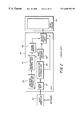
- FIG. 4 illustrates the details of a laser exposure portion of a typical print engine. It includes the normal datapath electronics that drive the laser subsystem. SCSI interface 76 communicates to the front end CPU 74 which separates the image data from command data and sends the image data to the image pipeline which includes RIP 50 , frame-store 61 , laser interface 66 and laser scanner 4 .
- RIP 50 could be incorporated into the host computer 40 or between host computer 40 and print engine 60 .
- the Sun Microsystem NEWS-PRINT system is based on this type of architecture. Alternatively, RIP 50 could reside in the print engine as shown in FIG. 4 .
- the Hewlett-Packard LASER-JET series printer and the Apple LASERWRITER printer follow the second arrangement where the RIP is placed on board the printer.
- the basic elements and the way that the RIP functions is as explained earlier in conjunction with FIG. 2 .
- the commands separated by the front end CPU 74 are either for print engine control or for datapath control. In the former case, they are redirected to the LCU 63 . In the latter case, the commands are executed by the CPU 74 and/or RIP 50 .
- Frame-store 61 stores the bit-mapped information for each color separation of each image.
- U.S. Pat. No. 5,175,628 shows how the frame-store can be used to store and retrieve image color separation in different sequences to allow for printing of multiple images on a single sheet of a receiver. Depending on how many images are put on a single sheet, the final print is referred to 9-up, 4-up, etc.
- the laser interface 66 synchronizes the retrieval of image data from the frame-store 61 to the exposure of data by the laser scanner 4 .
- Each facet of the polygon 35 are detected by laser interface 66 and accordingly, one raster line of data is retrieved from the frame-store 61 .
- Image data is corrected through a look-up table for proper tone reproduction and is sent to the laser diode 34 pixel by pixel.
- the optics of laser sub-system 36 will focus the laser beam 3 onto the photoconductor 29 on drum 1 .
- Laser interface 66 counts the total number of pixels, as they are exposed, until the entire raster line is exposed. It also counts the number of raster lines as they are exposed until the entire image separation is exposed. The same is done for the color image separations. Once the 3 or 4 separations are exposed, the process is repeated with new bit-mapped image data in frame-store 61 for the printed page 2.
- SCSI interface 76 could be combined with input unit 51 .
- front end CPU 74 and interpretation unit 55 frame-store 61 and frame memory 56 and page buffer 53 .
- the frame-store 61 is a key element and usually the most expensive. All electrophotographic printers require a full size frame-store for the page that they print. The reason is that once they begin to expose the photoconductor 29 , they cannot be stopped. Therefore, a full page of raster data must be present inside the frame-store 61 before printing begins.
- bitmap page there are several problems associated with saving the bitmap page at full resolution as practiced in the prior art.
- One is that it forces the RIP to process an increased data load to generate every single pixel of the high resolution bit-mapped page.
- the page memory needs to be of significant size if the pages are large (11 ⁇ 17) and a high resolution printer is used (500 dpi and higher).
- the other possible problem is the slow transfer of the bit-mapped image to the printer.
- a bit-mapped image is generated by the RIP in the computer and then is sent to the printer through serial, parallel, or network ports. The larger the image, the longer it takes to transfer the bit-mapped image for that page.
- the quality of the overall printing is raised so as to correspond to what is needed for the graphic designs that are to be printed.
- a large-capacity storage is required for storing the character pattern.
- a large amount of time is required to produce a character pattern from stored character information because of the high resolution of the character pattern which results in a lowering of the throughput that cannot be avoided.
- a large-capacity RAM is required to provide the frame-store because the entire area of the print image consists of a high-resolution image, which increases the cost of the system.
- FIG. 5 shows the elements of the preferred printing system that eliminates the problems described above.
- interpolator 72 between the frame-store and printer interface, allows for having different resolution print data streams before and after the interpolator. Following the teachings of the present invention, only low resolution print data stream is handled in all the print system elements of FIG. 5 that are to the left of the interpolator. As explained earlier, storing low resolution print data in frame-store 61 translates into the use of a smaller frame-store. It also means shorter time periods to transmit print data from RIP 50 to frame-store 61 . The RIP 50 will also perform considerably fewer computations while generating the bit-mapped print data at a lower resolution. Interpolator 72 will increase the print data stream resolution to the resolution of print engine 60 . The elements in the printing system to the right of the interpolator will function at the higher resolution of the print engine as explained earlier in FIG. 1 .
- FIG. 6 shows the data path for handling the images in the preferred system.
- Files created with the page description language (PDL) are sent to the host computer 40 through a connection to a computer network 39 alternatively they could have been generated by host computer 40 .
- RIP 50 is shown located in the host computer 40 , but as mentioned earlier, could also be located within the printer.
- the image data from the host computer 40 is routed through RIP 50 directly to the SCSI interface 76 in the print engine.
- the SCSI interface 76 provides the proper connection to the CPU 74 which is the electronic front end and distinguishes image data from command information.
- the image information is directed to frame-store 61 for temporary storage, while the command information is sent to the print engine LCU 63 or handled by CPU 74 .
- Image data is stored in frame-store 61 until a proper print format is established (i.e., 4-up, 9-up, etc.). Raster lines of the print are read out of frame-store 61 line-by-line and sent to the interpolator 72 . Interpolator 72 will increase the resolution of the image data so that the proper image size could be reproduced, for example, 9-up is printed on “12 ⁇ 18” paper for nine 4′′ ⁇ 6′′ prints. The interpolated raster lines are then directed to the edge enhancer 70 . The amount of boost or sharpening applied by edge enhancer 70 is controlled by CPU 74 via the boost control command line.
- a proper print format i.e., 4-up, 9-up, etc.
- the amount of boost is based on information received by CPU 74 as to the type of film being scanned by the input scanner and that information is sent as command information by the host computer 40 .
- Film type has a direct effect on the amount of enhancement because it is based on the amount of grain in the film.
- the amount of enhancement is also varied if the page contains only graphic designs and characters.
- Enhanced raster lines are buffered and synchronized through the laser interface 66 to the laser scanner 4 .
- Laser beam 3 is then used to expose photoconductor 29 to form a latent image.
- Plan it is the plan to use the computing power of the host computer 40 for rasterizing the pages.
- Plans were made to use what is referred to as a software RIP.
- a separate dedicated card that can do the RIP work is also optional (hardware RIP).
- the key to the plan is to instruct the RIP to generate the bitmap page for a low resolution printer, i.e., 250 dpi or 200 dpi. This small and low resolution page is transferred quickly to the frame-store.
- the interpolator is instructed to operate at the correct ratio, say, 2 or 2.5, respectively, and the image is printed at a full 500 dpi.
- interpolation ratios can be as high as 6 for images before noticeable image degradation is visible.
- the same type simulation was just undertaken. The initial estimate is that the interpolation ratio could be as high as 3 for text and line art. It is clear that RIP time could be reduced by a factor of 9 (the square of 3) with this concept without significant image quality degradation.
- the size of the frame-store could be reduced by a factor of 9. This is because the size of the bitmap page is reduced by the square of the interpolation ratio. Another significant factor is the reduction in time to transfer the bitmap page from RIP to frame-store over the SCSI channel. Again, this time could be reduced by a factor of 9.
- the frame-store data rate during exposure is reduced by the square ratio of interpolation. For example, if the interpolation ratio is at 3, then the data rate of the frame-store will be ⁇ fraction (1/9) ⁇ of the full resolution case which is the maximum bandwidth of the frame-store. Therefore, we have ⁇ fraction (8/9) ⁇ of the bandwidth available for loading the next image into the frame-store. Thus, we could be processing the next page while printing the present one simultaneously.
- a software RIP can work at any resolution with a mere input command from the host computer, but on the other hand, most traditional hardware RIPs have only one working resolution and cannot readily be changed to a different resolution.
- the interpolator converts the resolution of the stored image in the frame-store to the printer resolution.
- the printer resolution is fixed at 500 dpi.
- the stored image resolution can be any number since the interpolator can interpolate at any ratio (for example, 1.953 or 2.000).
- FIG. 7 shows an example of a 2x interpolation. The point shown with “0” are the original low resolution data points of the image. The points marked “x” are the calculated pixels of the new higher resolution image. Notice how the number of data points has increased considerably by a simple 2x interpolation (interpolation ratio is equal to 2.000).
- FIG. 9 is a schematic block diagram showing an interpolator according to the present invention.
- the interpolator receives digital image pixel data, for example, from a frame-store memory (not shown) one row at a time and produces interpolated digital image data one row at a time which can be supplied to a printer (not shown) or stored for future use, for example, in a frame-store.
- the interpolator includes a logic and control circuit 110 which calculates a horizontal sampling increment h H and a vertical sampling increment h V for the output images and controls the overall operation of the interpolator.
- the sampling increment h is determined by magnification factors that can represent expansion, reduction, or no change in the number of pixels in the image in the horizontal and vertical directions.
- the interpolator includes a row interpolator 112 , a column interpolator 114 , an interpolation kernel look-up table 116 and an output buffer 118 .
- the logic and control unit 110 receives instructions regarding the number and size of input images to be printed on a particular output format, and calculates magnification factors to be applied to each image, based on the number of pixels in the original image, and the number of pixels to be provided in the interpolated output image.
- the row interpolator 112 retrieves pixel values along a row and interpolates pixel values P′ between them by retrieving interpolation coefficients from the one-dimensional interpolation kernel look-up table 116 .
- the row interpolator multiplies the pixel values by their respective interpolation coefficients and sums the product to produce the interpolated values.
- the interpolated pixel values P′ from the row interpolator are supplied upon request to the column interpolator 114 on line 120 .
- the column interpolator 114 requests data on line 122 and when the row interpolator 112 supplies the data, an acknowledgment is supplied on line 124 .
- the column interpolator 114 acquires and stores several rows of interpolated pixel data until it can start performing interpolation in a column direction on the stored data. When sufficient data has been acquired, the column interpolator 114 begins interpolating in a column direction to produce rows of interpolated values P′′ between the rows supplied by the row interpolator 112 .
- the column interpolator 114 interpolates in a column direction by selecting a plurality of pixel values arranged in a column from the acquired rows, retrieving a corresponding plurality of interpolation coefficients from the look-up table 116 and performing multiplication and addition of the products in a manner similar to the row interpolator 112 .
- the coefficients are derived from different interpolation kernels, for example, cubic convolution interpolation kernel 144 and 146 or the linear interpolation kernel 148 or replication kernel 150 , depending on image content.
- the column interpolator 114 provides rows of interpolated pixel values P′′ to the output buffer 118 , which is double buffered so that a row of interpolated pixel values can be read out while the next row is being read into the output buffer 118 .
- Double buffering is produced as is known in the art by a pair of buffers 126 and 128 and multiplex switches 130 and 132 .
- x ⁇ x k is a value of the interpolation kernel at location (x ⁇ x k ); h is the sample increment of the interpolated function, x k represents the location of the samples of input data (also called interpolation nodes) and P k are the values of the input data at the interpolation nodes.
- the interpolation kernel is a continuous function that converts sampled data into a continuous function, the resulting continuous function can then be re-sampled to obtain the interpolated sample values.
- Cubic convolution employs a kernel that is defined by piecewise cubic polynomials defined on the subintervals ( ⁇ 2, ⁇ 1), ( ⁇ 1,0), (0,1) and (1,2). Outside the interval ( ⁇ 2,2) the kernel is zero. Evaluation of equation 1 for the cubic convolution interpolation kernel requires four consecutive data samples from the original image data.
- FIG. 10 is a graph showing the cubic convolution interpolation kernel 134 defined on the interval ( ⁇ 2,2). The scale of the X axis in FIG. 10 is equivalent to the spacing of the data samples in the original image.
- stage I the cubic convolution interpolation kernel is moved horizontally over the original pixels (0's) until all the necessary new pixels (X's) of a line are generated. Then, the cubic convolution interpolation kernel is moved vertically by h amount. As shown in FIG. 8, “h” is the sampling interval and explained by equation (4) of the Kerr patent discussed later. Now another row of new pixels (X's) are generated by repeating the steps explained above and using equation (2).
- Stage II of interpolation i.e., horizontal is done in the lower part of FIG. 8 .
- the steps for vertical interpolation are repeated similarly.
- One difference is that the cubic convolution interpolation kernel is moved over original pixels vertically first to create a new column and then stepped horizontally by step h.
- FIG. 11 illustrates how the cubic convolution interpolation kernel 134 is employed to compute an interpolated value at location x.
- Four consecutive data values from the original image data are shown as A, B, C and D.
- the interpolation kernel 134 is centered at x, and the values of the kernel are calculated at the locations of the original data samples.
- These values C A , C B , C C and C D are the interpolation coefficients.
- the interpolated value at x is:
- a value at any location between original sample points B and C can be computed in this manner.
- the coefficient values are calculated from the piecewise cubic polynomials defining the kernel, and stored in the lookup table 116 (see FIG. 9 ).
- the kernel is evaluated at 1,024 points to 16-bit accuracy.
- the resulting 1,024 coefficients are divided into four groups, representing the four segments of the kernel between ( ⁇ 2, ⁇ 1), ( ⁇ 1,0), (0,1) and (1,2) each group having 256 coefficients.
- the four groups are stored in look-up table 116 which can be simultaneously addressed by a displacement value d that represents the distance from the zero in the kernel ⁇ 1 to the sample B.
- the arrangement of the interpolation kernel lookup tables is shown in FIG. 12 where the first memory bank 136 contains the 256 coefficients that define the kernel on the interval ( ⁇ 2, ⁇ 1). Similarly, the second memory bank 138 contains the groups of coefficients representing the portion of the convolution kernel from ( ⁇ 1,0), and so on for memory banks 140 and 142 .
- a displacement value d is simultaneously applied to all four memory banks to produce coefficients C 1 , C 2 , C 3 and C 4 .
- the interpolation kernel lookup table may contain kernels for any number of other types of interpolation such as linear and replication, in addition to different types of cubic convolution.
- the interpolation lookup table also contains a kernel for linear interpolation 148 and a kernel for replication 150 .
- the kernel for linear interpolation is shown in FIG. 13 and is graphically represented as a triangular waveform in the interval ( ⁇ 1,1) and zero elsewhere.
- the kernel for replication is shown in FIG. 14 and is graphically represented as a step function having a value of one in the interval ( ⁇ 2, ⁇ 1) and zero elsewhere.
- the logic and control circuit 110 selects the lookup table addressed by the interpolators 112 and 114 in response to an operator input specifying the interpolation procedure that is desired. For example, it is known that replication interpolation performs better on binary images such as text, thus the nearest neighbor kernel may be selected for performing interpolation on text portions of an image.
- the sampling increment h is determined by the logic and control unit 110 by first determining a magnification factor M defined as the lesser of the two ratios x′/x, y′/y, where x is the number of pixels in the original image in the horizontal direction, and x is the number of pixels available on the output printer for printing the original image.
- M magnification factor
- the number of available pixels on the output medium is determined by the output format including the width of the output medium and the number of input images to be printed across the page in the output image.
- y represents the number of pixels in an input image in the vertical direction
- y′ represents the number of pixels available to print the image in the vertical direction.
- the lesser of the two ratios is chosen so that the reproduced image will not be cropped.
- the sampling increment h is computed to an accuracy of 24 bits.
- interpolation is done by providing a digital image process for performing two-dimensional interpolation, having an interpolation coefficient memory containing interpolation coefficients representing a one-dimensional interpolation kernel.
- a row interpolator connected to the memory receives image pixel values along a row, retrieves interpolation coefficients from the memory and produces interpolated pixel values by interpolating in the row direction.
- a column interpolator connected to the memory and to the new interpolator receives rows of interpolated pixel values from the row interpolator, retrieves interpolation coefficients from the coefficient memory and produces rows of interpolated pixel values by interpolating in a column direction.
- the interpolation coefficient memory contains a plurality of interpolation kernels for performing different types of interpolation such as cubic convolution, linear and replication, and the interpolator includes a logic and control unit for selecting one of the interpolation kernels in response to an operator input.
- the interpolation coefficients are stored in a plurality of banks in the memory, and the banks are simultaneously addressed to return a plurality of coefficients, one coefficient from each bank.
- the row interpolator includes control means for replicating the first and last pixel in a row in an image so that interpolation values can be computed between the first and second pixels of an image row, and between the last and next to last pixels of a row.
- the column interpolator includes control means for replicating the first and last columns of an image for interpolating between the first and second columns, and between the last and next to last columns of an image.
- U.S. Pat. No. 5,125,042, issued to R. Kerr et al contains detailed information about an interpolator that could be used in conjunction with the present disclosure.
Abstract
Description


Claims (7)
Priority Applications (1)
| Application Number | Priority Date | Filing Date | Title |
|---|---|---|---|
| US08/085,605 US6680782B1 (en) | 1993-06-30 | 1993-06-30 | Method and apparatus of using a raster image processor and interpolator to increase the speed of operation and reduce memory requirements for electronic printing |
Applications Claiming Priority (1)
| Application Number | Priority Date | Filing Date | Title |
|---|---|---|---|
| US08/085,605 US6680782B1 (en) | 1993-06-30 | 1993-06-30 | Method and apparatus of using a raster image processor and interpolator to increase the speed of operation and reduce memory requirements for electronic printing |
Publications (1)
| Publication Number | Publication Date |
|---|---|
| US6680782B1 true US6680782B1 (en) | 2004-01-20 |
Family
ID=29998866
Family Applications (1)
| Application Number | Title | Priority Date | Filing Date |
|---|---|---|---|
| US08/085,605 Active 2026-01-20 US6680782B1 (en) | 1993-06-30 | 1993-06-30 | Method and apparatus of using a raster image processor and interpolator to increase the speed of operation and reduce memory requirements for electronic printing |
Country Status (1)
| Country | Link |
|---|---|
| US (1) | US6680782B1 (en) |
Cited By (10)
| Publication number | Priority date | Publication date | Assignee | Title |
|---|---|---|---|---|
| US20030220759A1 (en) * | 2000-06-13 | 2003-11-27 | Takeshi Katayama | Fail analyzer |
| US20040205603A1 (en) * | 2001-10-03 | 2004-10-14 | Nguyen Truc D. | Method to dynamically perform document layout functions |
| US20060152597A1 (en) * | 2004-12-27 | 2006-07-13 | Casio Computer Co., Ltd. | Pixel interpolation device and camera adapted to perform pixel interpolation of captured image |
| US20070047812A1 (en) * | 2005-08-25 | 2007-03-01 | Czyszczewski Joseph S | Apparatus, system, and method for scanning segmentation |
| US20070052982A1 (en) * | 2005-09-07 | 2007-03-08 | Kabushiki Kaisha Toshiba | Color image forming apparatus and image forming method |
| US20070177204A1 (en) * | 2006-02-02 | 2007-08-02 | Atsushi Kamasuka | Code information printing apparatus, printing method, restoration apparatus, and restoration method |
| US20080211819A1 (en) * | 2007-03-01 | 2008-09-04 | Konica Minolta Systems Laboratory, Inc. | Raster image processor using a self-tuning banding mode |
| US20120019860A1 (en) * | 2010-07-23 | 2012-01-26 | Satoko Fujiwara | Image forming apparatus, method of controlling the same, and image processing apparatus |
| US8681363B2 (en) | 2012-01-31 | 2014-03-25 | Hewlett-Packard Development Company, L.P. | Raster application instances |
| US9361556B1 (en) * | 2006-07-27 | 2016-06-07 | Marvell International Ltd. | Pulse width modulator for a printing device |
Citations (24)
| Publication number | Priority date | Publication date | Assignee | Title |
|---|---|---|---|---|
| US3573789A (en) | 1968-12-13 | 1971-04-06 | Ibm | Method and apparatus for increasing image resolution |
| US4124870A (en) | 1977-03-31 | 1978-11-07 | International Business Machines Corporation | Method for improving print quality of coarse-scan/fine-print character reproduction |
| US4193092A (en) | 1978-06-21 | 1980-03-11 | Xerox Corporation | Image interpolation system |
| US4303947A (en) | 1978-06-21 | 1981-12-01 | Xerox Corporation | Image interpolation system |
| US4384336A (en) | 1980-08-29 | 1983-05-17 | Polaroid Corporation | Method and apparatus for lightness imaging |
| US4549222A (en) | 1982-03-04 | 1985-10-22 | Ing. C. Olivetti & C., S.P.A. | Dot matrix printing method and printer therefor |
| US4595958A (en) | 1984-08-24 | 1986-06-17 | Minnesota Mining And Manufacturing Company | Multiformat image recordation |
| US4610536A (en) | 1985-05-06 | 1986-09-09 | Polaroid Corporation | Laser scanning and printing apparatus |
| US4649568A (en) | 1984-10-22 | 1987-03-10 | Polaroid Corporation | Reconstitution of images |
| US4661987A (en) | 1985-06-03 | 1987-04-28 | The United States Of America As Represented By The Secretary Of The Navy | Video processor |
| US4722064A (en) * | 1984-11-27 | 1988-01-26 | Fuji Xerox Co., Ltd. | Drawing output unit |
| US4881180A (en) * | 1986-03-05 | 1989-11-14 | Minolta Camera Kabushiki Kaisha | Character image generating circuit |
| US5047955A (en) | 1987-06-19 | 1991-09-10 | Eastman Kodak Company | Electronic collation |
| US5097518A (en) | 1990-02-27 | 1992-03-17 | Eastman Kodak Company | Technique for performing digital image scaling by logically combining or replicating pixels in blocks of differing groupsizes |
| US5113494A (en) | 1987-02-27 | 1992-05-12 | Eastman Kodak Company | High speed raster image processor particularly suited for use in an image management system |
| US5113455A (en) | 1990-02-27 | 1992-05-12 | Eastman Kodak Company | Digital image scaling by stepwise pixel movement |
| US5125042A (en) | 1989-06-16 | 1992-06-23 | Eastman Kodak Company | Digital image interpolator using a plurality of interpolation kernals |
| US5125072A (en) | 1989-07-31 | 1992-06-23 | Eastman Kodak Company | Efficient data storage system for gray-scale printers |
| US5146547A (en) * | 1989-08-28 | 1992-09-08 | Lexmark International, Inc. | Printer buffer and rasterization arrangement |
| US5157417A (en) | 1989-09-26 | 1992-10-20 | Canon Kabushiki Kaisha | Printing apparatus |
| US5168375A (en) * | 1991-09-18 | 1992-12-01 | Polaroid Corporation | Image reconstruction by use of discrete cosine and related transforms |
| US5347368A (en) * | 1991-01-31 | 1994-09-13 | Fuji Photo Film Co., Ltd. | Image recording apparatus having a small-capacity frame memory and an image recording method |
| US5351074A (en) * | 1988-01-19 | 1994-09-27 | Canon Kabushiki Kaisha | Apparatus for forming a color image using two memories |
| US5377023A (en) * | 1989-02-02 | 1994-12-27 | Dai Nippon Insatsu Kabushiki Kaisha | Pictorial image processing system |
-
1993
- 1993-06-30 US US08/085,605 patent/US6680782B1/en active Active
Patent Citations (24)
| Publication number | Priority date | Publication date | Assignee | Title |
|---|---|---|---|---|
| US3573789A (en) | 1968-12-13 | 1971-04-06 | Ibm | Method and apparatus for increasing image resolution |
| US4124870A (en) | 1977-03-31 | 1978-11-07 | International Business Machines Corporation | Method for improving print quality of coarse-scan/fine-print character reproduction |
| US4193092A (en) | 1978-06-21 | 1980-03-11 | Xerox Corporation | Image interpolation system |
| US4303947A (en) | 1978-06-21 | 1981-12-01 | Xerox Corporation | Image interpolation system |
| US4384336A (en) | 1980-08-29 | 1983-05-17 | Polaroid Corporation | Method and apparatus for lightness imaging |
| US4549222A (en) | 1982-03-04 | 1985-10-22 | Ing. C. Olivetti & C., S.P.A. | Dot matrix printing method and printer therefor |
| US4595958A (en) | 1984-08-24 | 1986-06-17 | Minnesota Mining And Manufacturing Company | Multiformat image recordation |
| US4649568A (en) | 1984-10-22 | 1987-03-10 | Polaroid Corporation | Reconstitution of images |
| US4722064A (en) * | 1984-11-27 | 1988-01-26 | Fuji Xerox Co., Ltd. | Drawing output unit |
| US4610536A (en) | 1985-05-06 | 1986-09-09 | Polaroid Corporation | Laser scanning and printing apparatus |
| US4661987A (en) | 1985-06-03 | 1987-04-28 | The United States Of America As Represented By The Secretary Of The Navy | Video processor |
| US4881180A (en) * | 1986-03-05 | 1989-11-14 | Minolta Camera Kabushiki Kaisha | Character image generating circuit |
| US5113494A (en) | 1987-02-27 | 1992-05-12 | Eastman Kodak Company | High speed raster image processor particularly suited for use in an image management system |
| US5047955A (en) | 1987-06-19 | 1991-09-10 | Eastman Kodak Company | Electronic collation |
| US5351074A (en) * | 1988-01-19 | 1994-09-27 | Canon Kabushiki Kaisha | Apparatus for forming a color image using two memories |
| US5377023A (en) * | 1989-02-02 | 1994-12-27 | Dai Nippon Insatsu Kabushiki Kaisha | Pictorial image processing system |
| US5125042A (en) | 1989-06-16 | 1992-06-23 | Eastman Kodak Company | Digital image interpolator using a plurality of interpolation kernals |
| US5125072A (en) | 1989-07-31 | 1992-06-23 | Eastman Kodak Company | Efficient data storage system for gray-scale printers |
| US5146547A (en) * | 1989-08-28 | 1992-09-08 | Lexmark International, Inc. | Printer buffer and rasterization arrangement |
| US5157417A (en) | 1989-09-26 | 1992-10-20 | Canon Kabushiki Kaisha | Printing apparatus |
| US5097518A (en) | 1990-02-27 | 1992-03-17 | Eastman Kodak Company | Technique for performing digital image scaling by logically combining or replicating pixels in blocks of differing groupsizes |
| US5113455A (en) | 1990-02-27 | 1992-05-12 | Eastman Kodak Company | Digital image scaling by stepwise pixel movement |
| US5347368A (en) * | 1991-01-31 | 1994-09-13 | Fuji Photo Film Co., Ltd. | Image recording apparatus having a small-capacity frame memory and an image recording method |
| US5168375A (en) * | 1991-09-18 | 1992-12-01 | Polaroid Corporation | Image reconstruction by use of discrete cosine and related transforms |
Non-Patent Citations (1)
| Title |
|---|
| US 5,206,741, 4/1993, Shimura et al. (withdrawn) * |
Cited By (18)
| Publication number | Priority date | Publication date | Assignee | Title |
|---|---|---|---|---|
| US20030220759A1 (en) * | 2000-06-13 | 2003-11-27 | Takeshi Katayama | Fail analyzer |
| US20040205603A1 (en) * | 2001-10-03 | 2004-10-14 | Nguyen Truc D. | Method to dynamically perform document layout functions |
| US6894804B2 (en) * | 2001-10-03 | 2005-05-17 | Toshiba Tec Kabushiki Kaisha | Method to dynamically perform document layout functions |
| US20060152597A1 (en) * | 2004-12-27 | 2006-07-13 | Casio Computer Co., Ltd. | Pixel interpolation device and camera adapted to perform pixel interpolation of captured image |
| US7693350B2 (en) * | 2004-12-27 | 2010-04-06 | Casio Computer Co., Ltd. | Pixel interpolation device and camera adapted to perform pixel interpolation of captured image |
| US7599556B2 (en) * | 2005-08-25 | 2009-10-06 | Joseph Stanley Czyszczewski | Apparatus, system, and method for scanning segmentation |
| US20070047812A1 (en) * | 2005-08-25 | 2007-03-01 | Czyszczewski Joseph S | Apparatus, system, and method for scanning segmentation |
| US20070052982A1 (en) * | 2005-09-07 | 2007-03-08 | Kabushiki Kaisha Toshiba | Color image forming apparatus and image forming method |
| US20070177204A1 (en) * | 2006-02-02 | 2007-08-02 | Atsushi Kamasuka | Code information printing apparatus, printing method, restoration apparatus, and restoration method |
| US20070177227A1 (en) * | 2006-02-02 | 2007-08-02 | Atsushi Kamasuka | Code information printing apparatus, printing method, restoration apparatus, and restoration method |
| US8179547B2 (en) * | 2006-02-02 | 2012-05-15 | Canon Kabushiki Kaisha | Code information printing apparatus, printing method, restoration apparatus, and restoration method |
| US7957038B2 (en) | 2006-02-02 | 2011-06-07 | Canon Kabushiki Kaisha | Code information printing apparatus, printing method, restoration apparatus, and restoration method |
| US9361556B1 (en) * | 2006-07-27 | 2016-06-07 | Marvell International Ltd. | Pulse width modulator for a printing device |
| US20080211819A1 (en) * | 2007-03-01 | 2008-09-04 | Konica Minolta Systems Laboratory, Inc. | Raster image processor using a self-tuning banding mode |
| US8665482B2 (en) * | 2007-03-01 | 2014-03-04 | Konica Minolta Laboratory U.S.A., Inc. | Raster image processor using a self-tuning banding mode |
| US8570575B2 (en) * | 2010-07-23 | 2013-10-29 | Ricoh Company, Limited | Image forming apparatus, method of controlling the same, and image processing apparatus performing image formation on the basis of a plurality of pieces of image data for different colors |
| US20120019860A1 (en) * | 2010-07-23 | 2012-01-26 | Satoko Fujiwara | Image forming apparatus, method of controlling the same, and image processing apparatus |
| US8681363B2 (en) | 2012-01-31 | 2014-03-25 | Hewlett-Packard Development Company, L.P. | Raster application instances |
Similar Documents
| Publication | Publication Date | Title |
|---|---|---|
| EP0703524B1 (en) | Variable data fields in a page description language | |
| US7268910B2 (en) | Just-in-time raster image assembly | |
| US5796411A (en) | High resolution real time raster image processing system and method | |
| US5387985A (en) | Non-integer image resolution conversion using statistically generated look-up tables | |
| US6295133B1 (en) | Method and apparatus for modifying raster data | |
| US5835685A (en) | Page printer, resolution converting method, and variable-length reversible compression process | |
| US6594034B1 (en) | Method and apparatus for modifying raster data | |
| US6680782B1 (en) | Method and apparatus of using a raster image processor and interpolator to increase the speed of operation and reduce memory requirements for electronic printing | |
| EP0727732B1 (en) | Output control method and apparatus and computer program product | |
| US20030007167A1 (en) | Seamless multi-page spreads | |
| US5568269A (en) | Method and apparatus for scanning and printing documents with text and images | |
| EP0575134A2 (en) | Method and apparatus for printing according to a graphic language | |
| JP2662305B2 (en) | Figure selection method | |
| US5731800A (en) | Output method and apparatus | |
| JP3308663B2 (en) | Image forming device | |
| JP4636145B2 (en) | Image processing apparatus and program | |
| JP3257567B2 (en) | Page image information processing apparatus and method | |
| JP3419450B2 (en) | Pixel data processing apparatus and method | |
| JP3281327B2 (en) | Information processing apparatus and information processing method | |
| JP3671633B2 (en) | Print data processing device | |
| JPH10151815A (en) | Printing-processing apparatus | |
| JPH09216349A (en) | Data processing method in page printer | |
| JP3778265B2 (en) | Image processing method and image processing apparatus | |
| JP3327744B2 (en) | Recording apparatus and method, and computer control apparatus | |
| JPH10157217A (en) | Printing-processing apparatus |
Legal Events
| Date | Code | Title | Description |
|---|---|---|---|
| AS | Assignment |
Owner name: EASTMAN KODAK COMPANY, NEW YORK Free format text: ASSIGNMENT OF ASSIGNORS INTEREST;ASSIGNOR:JAMZADEH, FERAYDOON S.;REEL/FRAME:006609/0816 Effective date: 19930630 |
|
| AS | Assignment |
Owner name: NEXPRESS SOLUTIONS LLC, NEW YORK Free format text: ASSIGNMENT OF ASSIGNORS INTEREST;ASSIGNOR:EASTMAN KODAK COMPANY;REEL/FRAME:012036/0959 Effective date: 20000717 |
|
| FEPP | Fee payment procedure |
Free format text: PAYOR NUMBER ASSIGNED (ORIGINAL EVENT CODE: ASPN); ENTITY STATUS OF PATENT OWNER: LARGE ENTITY |
|
| STCF | Information on status: patent grant |
Free format text: PATENTED CASE |
|
| AS | Assignment |
Owner name: EASTMAN KODAK COMPANY, NEW YORK Free format text: ASSIGNMENT OF ASSIGNORS INTEREST;ASSIGNOR:NEXPRESS SOLUTIONS, INC. (FORMERLY NEXPRESS SOLUTIONS LLC);REEL/FRAME:015928/0176 Effective date: 20040909 |
|
| FPAY | Fee payment |
Year of fee payment: 4 |
|
| FPAY | Fee payment |
Year of fee payment: 8 |
|
| AS | Assignment |
Owner name: CITICORP NORTH AMERICA, INC., AS AGENT, NEW YORK Free format text: SECURITY INTEREST;ASSIGNORS:EASTMAN KODAK COMPANY;PAKON, INC.;REEL/FRAME:028201/0420 Effective date: 20120215 |
|
| AS | Assignment |
Owner name: WILMINGTON TRUST, NATIONAL ASSOCIATION, AS AGENT, Free format text: PATENT SECURITY AGREEMENT;ASSIGNORS:EASTMAN KODAK COMPANY;PAKON, INC.;REEL/FRAME:030122/0235 Effective date: 20130322 Owner name: WILMINGTON TRUST, NATIONAL ASSOCIATION, AS AGENT, MINNESOTA Free format text: PATENT SECURITY AGREEMENT;ASSIGNORS:EASTMAN KODAK COMPANY;PAKON, INC.;REEL/FRAME:030122/0235 Effective date: 20130322 |
|
| AS | Assignment |
Owner name: JPMORGAN CHASE BANK, N.A., AS ADMINISTRATIVE, DELAWARE Free format text: INTELLECTUAL PROPERTY SECURITY AGREEMENT (FIRST LIEN);ASSIGNORS:EASTMAN KODAK COMPANY;FAR EAST DEVELOPMENT LTD.;FPC INC.;AND OTHERS;REEL/FRAME:031158/0001 Effective date: 20130903 Owner name: BARCLAYS BANK PLC, AS ADMINISTRATIVE AGENT, NEW YORK Free format text: INTELLECTUAL PROPERTY SECURITY AGREEMENT (SECOND LIEN);ASSIGNORS:EASTMAN KODAK COMPANY;FAR EAST DEVELOPMENT LTD.;FPC INC.;AND OTHERS;REEL/FRAME:031159/0001 Effective date: 20130903 Owner name: JPMORGAN CHASE BANK, N.A., AS ADMINISTRATIVE, DELA Free format text: INTELLECTUAL PROPERTY SECURITY AGREEMENT (FIRST LIEN);ASSIGNORS:EASTMAN KODAK COMPANY;FAR EAST DEVELOPMENT LTD.;FPC INC.;AND OTHERS;REEL/FRAME:031158/0001 Effective date: 20130903 Owner name: PAKON, INC., NEW YORK Free format text: RELEASE OF SECURITY INTEREST IN PATENTS;ASSIGNORS:CITICORP NORTH AMERICA, INC., AS SENIOR DIP AGENT;WILMINGTON TRUST, NATIONAL ASSOCIATION, AS JUNIOR DIP AGENT;REEL/FRAME:031157/0451 Effective date: 20130903 Owner name: BARCLAYS BANK PLC, AS ADMINISTRATIVE AGENT, NEW YO Free format text: INTELLECTUAL PROPERTY SECURITY AGREEMENT (SECOND LIEN);ASSIGNORS:EASTMAN KODAK COMPANY;FAR EAST DEVELOPMENT LTD.;FPC INC.;AND OTHERS;REEL/FRAME:031159/0001 Effective date: 20130903 Owner name: EASTMAN KODAK COMPANY, NEW YORK Free format text: RELEASE OF SECURITY INTEREST IN PATENTS;ASSIGNORS:CITICORP NORTH AMERICA, INC., AS SENIOR DIP AGENT;WILMINGTON TRUST, NATIONAL ASSOCIATION, AS JUNIOR DIP AGENT;REEL/FRAME:031157/0451 Effective date: 20130903 Owner name: BANK OF AMERICA N.A., AS AGENT, MASSACHUSETTS Free format text: INTELLECTUAL PROPERTY SECURITY AGREEMENT (ABL);ASSIGNORS:EASTMAN KODAK COMPANY;FAR EAST DEVELOPMENT LTD.;FPC INC.;AND OTHERS;REEL/FRAME:031162/0117 Effective date: 20130903 |
|
| FPAY | Fee payment |
Year of fee payment: 12 |
|
| AS | Assignment |
Owner name: EASTMAN KODAK COMPANY, NEW YORK Free format text: RELEASE BY SECURED PARTY;ASSIGNOR:BARCLAYS BANK PLC;REEL/FRAME:041656/0531 Effective date: 20170202 |
|
| AS | Assignment |
Owner name: KODAK REALTY, INC., NEW YORK Free format text: RELEASE BY SECURED PARTY;ASSIGNOR:JP MORGAN CHASE BANK, N.A., AS ADMINISTRATIVE AGENT;REEL/FRAME:050239/0001 Effective date: 20190617 Owner name: NPEC, INC., NEW YORK Free format text: RELEASE BY SECURED PARTY;ASSIGNOR:JP MORGAN CHASE BANK, N.A., AS ADMINISTRATIVE AGENT;REEL/FRAME:050239/0001 Effective date: 20190617 Owner name: KODAK IMAGING NETWORK, INC., NEW YORK Free format text: RELEASE BY SECURED PARTY;ASSIGNOR:JP MORGAN CHASE BANK, N.A., AS ADMINISTRATIVE AGENT;REEL/FRAME:050239/0001 Effective date: 20190617 Owner name: LASER PACIFIC MEDIA CORPORATION, NEW YORK Free format text: RELEASE BY SECURED PARTY;ASSIGNOR:JP MORGAN CHASE BANK, N.A., AS ADMINISTRATIVE AGENT;REEL/FRAME:050239/0001 Effective date: 20190617 Owner name: QUALEX, INC., NEW YORK Free format text: RELEASE BY SECURED PARTY;ASSIGNOR:JP MORGAN CHASE BANK, N.A., AS ADMINISTRATIVE AGENT;REEL/FRAME:050239/0001 Effective date: 20190617 Owner name: KODAK PHILIPPINES, LTD., NEW YORK Free format text: RELEASE BY SECURED PARTY;ASSIGNOR:JP MORGAN CHASE BANK, N.A., AS ADMINISTRATIVE AGENT;REEL/FRAME:050239/0001 Effective date: 20190617 Owner name: FPC, INC., NEW YORK Free format text: RELEASE BY SECURED PARTY;ASSIGNOR:JP MORGAN CHASE BANK, N.A., AS ADMINISTRATIVE AGENT;REEL/FRAME:050239/0001 Effective date: 20190617 Owner name: PAKON, INC., NEW YORK Free format text: RELEASE BY SECURED PARTY;ASSIGNOR:JP MORGAN CHASE BANK, N.A., AS ADMINISTRATIVE AGENT;REEL/FRAME:050239/0001 Effective date: 20190617 Owner name: KODAK (NEAR EAST), INC., NEW YORK Free format text: RELEASE BY SECURED PARTY;ASSIGNOR:JP MORGAN CHASE BANK, N.A., AS ADMINISTRATIVE AGENT;REEL/FRAME:050239/0001 Effective date: 20190617 Owner name: CREO MANUFACTURING AMERICA LLC, NEW YORK Free format text: RELEASE BY SECURED PARTY;ASSIGNOR:JP MORGAN CHASE BANK, N.A., AS ADMINISTRATIVE AGENT;REEL/FRAME:050239/0001 Effective date: 20190617 Owner name: FAR EAST DEVELOPMENT LTD., NEW YORK Free format text: RELEASE BY SECURED PARTY;ASSIGNOR:JP MORGAN CHASE BANK, N.A., AS ADMINISTRATIVE AGENT;REEL/FRAME:050239/0001 Effective date: 20190617 Owner name: EASTMAN KODAK COMPANY, NEW YORK Free format text: RELEASE BY SECURED PARTY;ASSIGNOR:JP MORGAN CHASE BANK, N.A., AS ADMINISTRATIVE AGENT;REEL/FRAME:050239/0001 Effective date: 20190617 Owner name: KODAK AVIATION LEASING LLC, NEW YORK Free format text: RELEASE BY SECURED PARTY;ASSIGNOR:JP MORGAN CHASE BANK, N.A., AS ADMINISTRATIVE AGENT;REEL/FRAME:050239/0001 Effective date: 20190617 Owner name: KODAK PORTUGUESA LIMITED, NEW YORK Free format text: RELEASE BY SECURED PARTY;ASSIGNOR:JP MORGAN CHASE BANK, N.A., AS ADMINISTRATIVE AGENT;REEL/FRAME:050239/0001 Effective date: 20190617 Owner name: KODAK AMERICAS, LTD., NEW YORK Free format text: RELEASE BY SECURED PARTY;ASSIGNOR:JP MORGAN CHASE BANK, N.A., AS ADMINISTRATIVE AGENT;REEL/FRAME:050239/0001 Effective date: 20190617 |
|
| AS | Assignment |
Owner name: KODAK AVIATION LEASING LLC, NEW YORK Free format text: RELEASE BY SECURED PARTY;ASSIGNOR:JP MORGAN CHASE BANK, N.A., AS ADMINISTRATIVE AGENT;REEL/FRAME:049901/0001 Effective date: 20190617 Owner name: FAR EAST DEVELOPMENT LTD., NEW YORK Free format text: RELEASE BY SECURED PARTY;ASSIGNOR:JP MORGAN CHASE BANK, N.A., AS ADMINISTRATIVE AGENT;REEL/FRAME:049901/0001 Effective date: 20190617 Owner name: KODAK PHILIPPINES, LTD., NEW YORK Free format text: RELEASE BY SECURED PARTY;ASSIGNOR:JP MORGAN CHASE BANK, N.A., AS ADMINISTRATIVE AGENT;REEL/FRAME:049901/0001 Effective date: 20190617 Owner name: NPEC, INC., NEW YORK Free format text: RELEASE BY SECURED PARTY;ASSIGNOR:JP MORGAN CHASE BANK, N.A., AS ADMINISTRATIVE AGENT;REEL/FRAME:049901/0001 Effective date: 20190617 Owner name: QUALEX, INC., NEW YORK Free format text: RELEASE BY SECURED PARTY;ASSIGNOR:JP MORGAN CHASE BANK, N.A., AS ADMINISTRATIVE AGENT;REEL/FRAME:049901/0001 Effective date: 20190617 Owner name: KODAK AMERICAS, LTD., NEW YORK Free format text: RELEASE BY SECURED PARTY;ASSIGNOR:JP MORGAN CHASE BANK, N.A., AS ADMINISTRATIVE AGENT;REEL/FRAME:049901/0001 Effective date: 20190617 Owner name: KODAK IMAGING NETWORK, INC., NEW YORK Free format text: RELEASE BY SECURED PARTY;ASSIGNOR:JP MORGAN CHASE BANK, N.A., AS ADMINISTRATIVE AGENT;REEL/FRAME:049901/0001 Effective date: 20190617 Owner name: KODAK REALTY, INC., NEW YORK Free format text: RELEASE BY SECURED PARTY;ASSIGNOR:JP MORGAN CHASE BANK, N.A., AS ADMINISTRATIVE AGENT;REEL/FRAME:049901/0001 Effective date: 20190617 Owner name: EASTMAN KODAK COMPANY, NEW YORK Free format text: RELEASE BY SECURED PARTY;ASSIGNOR:JP MORGAN CHASE BANK, N.A., AS ADMINISTRATIVE AGENT;REEL/FRAME:049901/0001 Effective date: 20190617 Owner name: PFC, INC., NEW YORK Free format text: RELEASE BY SECURED PARTY;ASSIGNOR:JP MORGAN CHASE BANK, N.A., AS ADMINISTRATIVE AGENT;REEL/FRAME:049901/0001 Effective date: 20190617 Owner name: KODAK PORTUGUESA LIMITED, NEW YORK Free format text: RELEASE BY SECURED PARTY;ASSIGNOR:JP MORGAN CHASE BANK, N.A., AS ADMINISTRATIVE AGENT;REEL/FRAME:049901/0001 Effective date: 20190617 Owner name: LASER PACIFIC MEDIA CORPORATION, NEW YORK Free format text: RELEASE BY SECURED PARTY;ASSIGNOR:JP MORGAN CHASE BANK, N.A., AS ADMINISTRATIVE AGENT;REEL/FRAME:049901/0001 Effective date: 20190617 Owner name: PAKON, INC., NEW YORK Free format text: RELEASE BY SECURED PARTY;ASSIGNOR:JP MORGAN CHASE BANK, N.A., AS ADMINISTRATIVE AGENT;REEL/FRAME:049901/0001 Effective date: 20190617 Owner name: CREO MANUFACTURING AMERICA LLC, NEW YORK Free format text: RELEASE BY SECURED PARTY;ASSIGNOR:JP MORGAN CHASE BANK, N.A., AS ADMINISTRATIVE AGENT;REEL/FRAME:049901/0001 Effective date: 20190617 Owner name: KODAK (NEAR EAST), INC., NEW YORK Free format text: RELEASE BY SECURED PARTY;ASSIGNOR:JP MORGAN CHASE BANK, N.A., AS ADMINISTRATIVE AGENT;REEL/FRAME:049901/0001 Effective date: 20190617 |
|
| AS | Assignment |
Owner name: KODAK (NEAR EAST) INC., NEW YORK Free format text: RELEASE BY SECURED PARTY;ASSIGNOR:BARCLAYS BANK PLC;REEL/FRAME:052773/0001 Effective date: 20170202 Owner name: KODAK AMERICAS LTD., NEW YORK Free format text: RELEASE BY SECURED PARTY;ASSIGNOR:BARCLAYS BANK PLC;REEL/FRAME:052773/0001 Effective date: 20170202 Owner name: FAR EAST DEVELOPMENT LTD., NEW YORK Free format text: RELEASE BY SECURED PARTY;ASSIGNOR:BARCLAYS BANK PLC;REEL/FRAME:052773/0001 Effective date: 20170202 Owner name: FPC INC., NEW YORK Free format text: RELEASE BY SECURED PARTY;ASSIGNOR:BARCLAYS BANK PLC;REEL/FRAME:052773/0001 Effective date: 20170202 Owner name: KODAK REALTY INC., NEW YORK Free format text: RELEASE BY SECURED PARTY;ASSIGNOR:BARCLAYS BANK PLC;REEL/FRAME:052773/0001 Effective date: 20170202 Owner name: QUALEX INC., NEW YORK Free format text: RELEASE BY SECURED PARTY;ASSIGNOR:BARCLAYS BANK PLC;REEL/FRAME:052773/0001 Effective date: 20170202 Owner name: LASER PACIFIC MEDIA CORPORATION, NEW YORK Free format text: RELEASE BY SECURED PARTY;ASSIGNOR:BARCLAYS BANK PLC;REEL/FRAME:052773/0001 Effective date: 20170202 Owner name: EASTMAN KODAK COMPANY, NEW YORK Free format text: RELEASE BY SECURED PARTY;ASSIGNOR:BARCLAYS BANK PLC;REEL/FRAME:052773/0001 Effective date: 20170202 Owner name: KODAK PHILIPPINES LTD., NEW YORK Free format text: RELEASE BY SECURED PARTY;ASSIGNOR:BARCLAYS BANK PLC;REEL/FRAME:052773/0001 Effective date: 20170202 Owner name: NPEC INC., NEW YORK Free format text: RELEASE BY SECURED PARTY;ASSIGNOR:BARCLAYS BANK PLC;REEL/FRAME:052773/0001 Effective date: 20170202 |
|
| AS | Assignment |
Owner name: ALTER DOMUS (US) LLC, ILLINOIS Free format text: INTELLECTUAL PROPERTY SECURITY AGREEMENT;ASSIGNOR:EASTMAN KODAK COMPANY;REEL/FRAME:056733/0681 Effective date: 20210226 Owner name: ALTER DOMUS (US) LLC, ILLINOIS Free format text: INTELLECTUAL PROPERTY SECURITY AGREEMENT;ASSIGNOR:EASTMAN KODAK COMPANY;REEL/FRAME:056734/0001 Effective date: 20210226 Owner name: ALTER DOMUS (US) LLC, ILLINOIS Free format text: INTELLECTUAL PROPERTY SECURITY AGREEMENT;ASSIGNOR:EASTMAN KODAK COMPANY;REEL/FRAME:056734/0233 Effective date: 20210226 Owner name: BANK OF AMERICA, N.A., AS AGENT, MASSACHUSETTS Free format text: NOTICE OF SECURITY INTERESTS;ASSIGNOR:EASTMAN KODAK COMPANY;REEL/FRAME:056984/0001 Effective date: 20210226 |