US6672572B2 - Packed column for exchanging heat and/or mass - Google Patents
Packed column for exchanging heat and/or mass Download PDFInfo
- Publication number
- US6672572B2 US6672572B2 US09/949,884 US94988401A US6672572B2 US 6672572 B2 US6672572 B2 US 6672572B2 US 94988401 A US94988401 A US 94988401A US 6672572 B2 US6672572 B2 US 6672572B2
- Authority
- US
- United States
- Prior art keywords
- packing module
- column
- packed column
- structured packing
- module
- Prior art date
- Legal status (The legal status is an assumption and is not a legal conclusion. Google has not performed a legal analysis and makes no representation as to the accuracy of the status listed.)
- Expired - Fee Related, expires
Links
Images

Classifications
-
- B—PERFORMING OPERATIONS; TRANSPORTING
- B01—PHYSICAL OR CHEMICAL PROCESSES OR APPARATUS IN GENERAL
- B01J—CHEMICAL OR PHYSICAL PROCESSES, e.g. CATALYSIS OR COLLOID CHEMISTRY; THEIR RELEVANT APPARATUS
- B01J19/00—Chemical, physical or physico-chemical processes in general; Their relevant apparatus
- B01J19/32—Packing elements in the form of grids or built-up elements for forming a unit or module inside the apparatus for mass or heat transfer
-
- F—MECHANICAL ENGINEERING; LIGHTING; HEATING; WEAPONS; BLASTING
- F25—REFRIGERATION OR COOLING; COMBINED HEATING AND REFRIGERATION SYSTEMS; HEAT PUMP SYSTEMS; MANUFACTURE OR STORAGE OF ICE; LIQUEFACTION SOLIDIFICATION OF GASES
- F25J—LIQUEFACTION, SOLIDIFICATION OR SEPARATION OF GASES OR GASEOUS OR LIQUEFIED GASEOUS MIXTURES BY PRESSURE AND COLD TREATMENT OR BY BRINGING THEM INTO THE SUPERCRITICAL STATE
- F25J3/00—Processes or apparatus for separating the constituents of gaseous or liquefied gaseous mixtures involving the use of liquefaction or solidification
- F25J3/02—Processes or apparatus for separating the constituents of gaseous or liquefied gaseous mixtures involving the use of liquefaction or solidification by rectification, i.e. by continuous interchange of heat and material between a vapour stream and a liquid stream
- F25J3/04—Processes or apparatus for separating the constituents of gaseous or liquefied gaseous mixtures involving the use of liquefaction or solidification by rectification, i.e. by continuous interchange of heat and material between a vapour stream and a liquid stream for air
- F25J3/04406—Processes or apparatus for separating the constituents of gaseous or liquefied gaseous mixtures involving the use of liquefaction or solidification by rectification, i.e. by continuous interchange of heat and material between a vapour stream and a liquid stream for air using a dual pressure main column system
- F25J3/04412—Processes or apparatus for separating the constituents of gaseous or liquefied gaseous mixtures involving the use of liquefaction or solidification by rectification, i.e. by continuous interchange of heat and material between a vapour stream and a liquid stream for air using a dual pressure main column system in a classical double column flowsheet, i.e. with thermal coupling by a main reboiler-condenser in the bottom of low pressure respectively top of high pressure column
-
- F—MECHANICAL ENGINEERING; LIGHTING; HEATING; WEAPONS; BLASTING
- F25—REFRIGERATION OR COOLING; COMBINED HEATING AND REFRIGERATION SYSTEMS; HEAT PUMP SYSTEMS; MANUFACTURE OR STORAGE OF ICE; LIQUEFACTION SOLIDIFICATION OF GASES
- F25J—LIQUEFACTION, SOLIDIFICATION OR SEPARATION OF GASES OR GASEOUS OR LIQUEFIED GASEOUS MIXTURES BY PRESSURE AND COLD TREATMENT OR BY BRINGING THEM INTO THE SUPERCRITICAL STATE
- F25J3/00—Processes or apparatus for separating the constituents of gaseous or liquefied gaseous mixtures involving the use of liquefaction or solidification
- F25J3/02—Processes or apparatus for separating the constituents of gaseous or liquefied gaseous mixtures involving the use of liquefaction or solidification by rectification, i.e. by continuous interchange of heat and material between a vapour stream and a liquid stream
- F25J3/04—Processes or apparatus for separating the constituents of gaseous or liquefied gaseous mixtures involving the use of liquefaction or solidification by rectification, i.e. by continuous interchange of heat and material between a vapour stream and a liquid stream for air
- F25J3/04763—Start-up or control of the process; Details of the apparatus used
- F25J3/04866—Construction and layout of air fractionation equipments, e.g. valves, machines
- F25J3/04896—Details of columns, e.g. internals, inlet/outlet devices
- F25J3/04909—Structured packings
-
- F—MECHANICAL ENGINEERING; LIGHTING; HEATING; WEAPONS; BLASTING
- F25—REFRIGERATION OR COOLING; COMBINED HEATING AND REFRIGERATION SYSTEMS; HEAT PUMP SYSTEMS; MANUFACTURE OR STORAGE OF ICE; LIQUEFACTION SOLIDIFICATION OF GASES
- F25J—LIQUEFACTION, SOLIDIFICATION OR SEPARATION OF GASES OR GASEOUS OR LIQUEFIED GASEOUS MIXTURES BY PRESSURE AND COLD TREATMENT OR BY BRINGING THEM INTO THE SUPERCRITICAL STATE
- F25J3/00—Processes or apparatus for separating the constituents of gaseous or liquefied gaseous mixtures involving the use of liquefaction or solidification
- F25J3/02—Processes or apparatus for separating the constituents of gaseous or liquefied gaseous mixtures involving the use of liquefaction or solidification by rectification, i.e. by continuous interchange of heat and material between a vapour stream and a liquid stream
- F25J3/04—Processes or apparatus for separating the constituents of gaseous or liquefied gaseous mixtures involving the use of liquefaction or solidification by rectification, i.e. by continuous interchange of heat and material between a vapour stream and a liquid stream for air
- F25J3/04763—Start-up or control of the process; Details of the apparatus used
- F25J3/04866—Construction and layout of air fractionation equipments, e.g. valves, machines
- F25J3/04896—Details of columns, e.g. internals, inlet/outlet devices
- F25J3/04915—Combinations of different material exchange elements, e.g. within different columns
- F25J3/04921—Combinations of different material exchange elements, e.g. within different columns within the same column
-
- F—MECHANICAL ENGINEERING; LIGHTING; HEATING; WEAPONS; BLASTING
- F25—REFRIGERATION OR COOLING; COMBINED HEATING AND REFRIGERATION SYSTEMS; HEAT PUMP SYSTEMS; MANUFACTURE OR STORAGE OF ICE; LIQUEFACTION SOLIDIFICATION OF GASES
- F25J—LIQUEFACTION, SOLIDIFICATION OR SEPARATION OF GASES OR GASEOUS OR LIQUEFIED GASEOUS MIXTURES BY PRESSURE AND COLD TREATMENT OR BY BRINGING THEM INTO THE SUPERCRITICAL STATE
- F25J3/00—Processes or apparatus for separating the constituents of gaseous or liquefied gaseous mixtures involving the use of liquefaction or solidification
- F25J3/02—Processes or apparatus for separating the constituents of gaseous or liquefied gaseous mixtures involving the use of liquefaction or solidification by rectification, i.e. by continuous interchange of heat and material between a vapour stream and a liquid stream
- F25J3/04—Processes or apparatus for separating the constituents of gaseous or liquefied gaseous mixtures involving the use of liquefaction or solidification by rectification, i.e. by continuous interchange of heat and material between a vapour stream and a liquid stream for air
- F25J3/04763—Start-up or control of the process; Details of the apparatus used
- F25J3/04866—Construction and layout of air fractionation equipments, e.g. valves, machines
- F25J3/04896—Details of columns, e.g. internals, inlet/outlet devices
- F25J3/04927—Liquid or gas distribution devices
-
- B—PERFORMING OPERATIONS; TRANSPORTING
- B01—PHYSICAL OR CHEMICAL PROCESSES OR APPARATUS IN GENERAL
- B01J—CHEMICAL OR PHYSICAL PROCESSES, e.g. CATALYSIS OR COLLOID CHEMISTRY; THEIR RELEVANT APPARATUS
- B01J2219/00—Chemical, physical or physico-chemical processes in general; Their relevant apparatus
- B01J2219/32—Details relating to packing elements in the form of grids or built-up elements for forming a unit of module inside the apparatus for mass or heat transfer
- B01J2219/322—Basic shape of the elements
- B01J2219/32203—Sheets
- B01J2219/3221—Corrugated sheets
-
- B—PERFORMING OPERATIONS; TRANSPORTING
- B01—PHYSICAL OR CHEMICAL PROCESSES OR APPARATUS IN GENERAL
- B01J—CHEMICAL OR PHYSICAL PROCESSES, e.g. CATALYSIS OR COLLOID CHEMISTRY; THEIR RELEVANT APPARATUS
- B01J2219/00—Chemical, physical or physico-chemical processes in general; Their relevant apparatus
- B01J2219/32—Details relating to packing elements in the form of grids or built-up elements for forming a unit of module inside the apparatus for mass or heat transfer
- B01J2219/322—Basic shape of the elements
- B01J2219/32203—Sheets
- B01J2219/32213—Plurality of essentially parallel sheets
- B01J2219/32217—Plurality of essentially parallel sheets with sheets having corrugations which intersect at an angle of 90 degrees
-
- B—PERFORMING OPERATIONS; TRANSPORTING
- B01—PHYSICAL OR CHEMICAL PROCESSES OR APPARATUS IN GENERAL
- B01J—CHEMICAL OR PHYSICAL PROCESSES, e.g. CATALYSIS OR COLLOID CHEMISTRY; THEIR RELEVANT APPARATUS
- B01J2219/00—Chemical, physical or physico-chemical processes in general; Their relevant apparatus
- B01J2219/32—Details relating to packing elements in the form of grids or built-up elements for forming a unit of module inside the apparatus for mass or heat transfer
- B01J2219/322—Basic shape of the elements
- B01J2219/32203—Sheets
- B01J2219/32224—Sheets characterised by the orientation of the sheet
- B01J2219/32227—Vertical orientation
-
- B—PERFORMING OPERATIONS; TRANSPORTING
- B01—PHYSICAL OR CHEMICAL PROCESSES OR APPARATUS IN GENERAL
- B01J—CHEMICAL OR PHYSICAL PROCESSES, e.g. CATALYSIS OR COLLOID CHEMISTRY; THEIR RELEVANT APPARATUS
- B01J2219/00—Chemical, physical or physico-chemical processes in general; Their relevant apparatus
- B01J2219/32—Details relating to packing elements in the form of grids or built-up elements for forming a unit of module inside the apparatus for mass or heat transfer
- B01J2219/322—Basic shape of the elements
- B01J2219/32203—Sheets
- B01J2219/32255—Other details of the sheets
-
- B—PERFORMING OPERATIONS; TRANSPORTING
- B01—PHYSICAL OR CHEMICAL PROCESSES OR APPARATUS IN GENERAL
- B01J—CHEMICAL OR PHYSICAL PROCESSES, e.g. CATALYSIS OR COLLOID CHEMISTRY; THEIR RELEVANT APPARATUS
- B01J2219/00—Chemical, physical or physico-chemical processes in general; Their relevant apparatus
- B01J2219/32—Details relating to packing elements in the form of grids or built-up elements for forming a unit of module inside the apparatus for mass or heat transfer
- B01J2219/324—Composition or microstructure of the elements
- B01J2219/32408—Metal
Definitions
- the present invention relates to a packed column for exchanging heat and/or mass between a descending liquid and a rising gas, of the type comprising at least one exchange section defined between an associated upper liquid distributor and a lower inlet/outlet for fluid or an associated lower liquid distributor, this exchange section comprising an upper portion and, below the latter, another portion. It is applicable in particular to air-distillation columns.
- packing refers to a device designed to promote intimate contact between a descending liquid and a rising gas, so that heat and/or mass exchange can take place.
- the packed portions each consist of at least one module or “pack” of packing.
- These modules may be of the random type, that is to say each consisting of a volume of discrete particles, but are preferably of what is known as the structured type. In this category, the following especially appear:
- Cross-corrugated packings generally consisting of corrugated strips comprising parallel alternating corrugations each one arranged in a vertical general plane and one against the others, the corrugations being oblique and descending in opposite directions from one strip to the next.
- the degree of perforation is typically about 10% for these cross-corrugated packings.
- GB-A-1 004 046 discloses packings of the cross-corrugated type
- CA-A-1 095 827 proposes an improvement on this type of packing by adding a dense arrangement of small-diameter perforations in order to allow the liquid to pass right through the cross-corrugated strips.
- Such a packing is generally manufactured from a flat product, namely metal sheets in the form of strips. The strips are firstly folded (or bent) so as to form a sort of corrugated metal plate in a strip, the corrugations of which are oblique with respect to the axis of the strip. The folded strips are then cut into portions and stacked, alternately turning around one band in two, so as to form modules or “packs”.
- Ventilated packings each module of which comprises a plurality of deflectors which define a set of horizontal layers of fixed ventilators for agitating the rising gas.
- ventilated packings are structures with a three-dimensional effect with regard to the gas which rises in the column. They ensure, by making the gas undergo multiple rotation, considerable turbulence in this gas, and the resultant agitation improves the exchange of heat and/or mass with the descending liquid.
- the aim of the invention is to reduce the cost of packed columns for exchanging heat and/or mass.
- the subject of the invention is a packed column of the aforementioned type, characterized in that the upper packed portion of at least one exchange section comprises at least one packing module which has a number of transfer units less than that of at least one packing module of the other packed portion of the same exchange section.
- the number of transfer units (NTU) in the vapour phase of a packing module is the ratio of the height of the module (HM) to the height of a transfer unit in the vapour phase (HTU).
- HTU HTU ⁇ ⁇ mV / L - 1 ln ⁇ ( mV / L )
- V molar vapour flow rate (mol/s)
- m slope of the equilibrium line in a graph showing the molar fraction in the vapour as a function of the molar fraction in the liquid.
- the HTU, and therefore the NTU, of a packing module depend to some extent on the fluids distilled and on the distillation conditions.
- NTUs of two packing modules are compared in this text, it is to be understood on each occasion that these two modules are placed in identical distillation conditions.
- the number of transfer units in vapour phase will be called the number of transfer units.
- the packed column according to the invention may comprise one or more of the following characteristics, taken alone or in all the technically possible combinations:
- the said module of the said upper portion differs from the said module of the said other portion of the same exchange section by at least one of the following factors:
- the said factor is the mean density, and the said upper portion ( 5 A) occupies only a fraction of the transverse section of the column, located under the jets of liquid coming from the said upper distributor;
- the said packed portions are portions of structured packing
- the said upper packed portion is a portion of cross-corrugated packing, while the other packed portion is a portion of ventilated packing;
- the said upper packed portion is a portion of cross-corrugated packing of relatively low density, while the other packed portion is a portion of cross-corrugated packing of higher density, the packing modules possibly being offset angularly, especially by 90°, one with respect to the others around the vertical central axis of the column;
- the said upper packed portion consists of a single packing module
- the said single module has a height lower than that of the modules of the other portion of the same exchange section;
- the packing modules are stacked one on top of the other, directly or with the insertion of elements forming spacers;
- the column is part of a double air-distillation column
- the other portion is a standard portion.
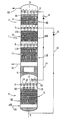
- the double air-distillation column 1 shown in the drawing, of vertical central axis X—X, has a conventional structure with the exception of the composition of its packings. It thus consists of a medium pressure column 2 surmounted by a low pressure column 3 .
- a main reboiler-condenser V puts the top vapour of column 2 (virtually pure nitrogen) in a heat exchange relationship with the bottom liquid (virtually pure oxygen) of column 3 .
- Column 2 comprises a top liquid distributor 4 and, below the latter, a single air-distillation section 5 .
- the column 3 comprises: a top liquid distributor 6 ; an upper intermediate liquid distributor 7 ; a lower intermediate liquid distributor 8 ; an upper distillation section 9 situated between the distributors 6 and 7 ; an intermediate distillation section 10 situated between the distributors 7 and 8 ; and a lower distillation section 11 situated below the distributor 8 .
- the air to be distilled, compressed to the medium pressure, typically about 5 bar absolute, is introduced into the bottom of the column 2 .
- “Rich liquid” (oxygen-enriched air) collected at the bottom of this column is drawn off via a pipe 12 , expanded to the lower pressure, which is about 1.2 bar absolute, in an expansion valve 13 , and introduced into the distributor 7 .
- “Lean liquid” from the top of the column 2 consisting of liquid nitrogen, is drawn off via a pipe 14 , expanded to a low pressure in an expansion valve 15 and introduced into the distributor 6 .
- the excess liquid nitrogen condensed in the reboiler-condenser V falls down inside the distributor 4 , which distributes it over the distillation section 5 . In the latter, the incoming air rises and exchanges heat and mass with the reflux liquid nitrogen thereby gradually becoming leaner in oxygen.
- the rising gas is gaseous oxygen, which exchanges heat and mass with the reflux liquid.
- the distributor 6 distributes liquid nitrogen over the distillation section 9 .
- the distributor 7 distributes, over the distillation section 10 , the rich liquid coming from the valve 13 together with the liquid of substantially the same composition which falls from the section 9 .
- the distributor 8 serves to redistribute, over the entire transverse section of the column 3 , the reflux liquid which leaves section 10 , in order to improve the distillation efficiency and to avoid the wall effect in which the liquid, after having crossed a certain height of packing, tends to trickle over the inner wall of the shell of the column.
- distributors for redistribution such as the distributor 8 , may be provided, depending on the packing type and on the column height.
- Each liquid distributor 4 , 6 , 7 , 8 comprises a peripheral duct 16 and several parallel ducts with a U-shaped section 17 which open at each end into the duct 16 .
- Parallel channels 18 are defined between the ducts 16 for the passage of the rising gas, the channels being closed by a horizontal upper wall 19 . Just under this wall, rows of windows 20 are made.
- the bottom of the ducts 17 is perforated, which defines a large number of vertical jets of liquid under each of these ducts.
- the double column 1 also comprises at least one product outlet such as a pipe 21 for drawing off gaseous oxygen from the bottom of the column 3 , located just under the section 11 , and a pipe 22 for drawing off waste gas (impure nitrogen) which leaves the top of the column 3 .
- the air inlet pipe at the bottom of the column 2 is indicated by 23 .
- Each of the distillation sections 5 , 9 , 10 , 11 consists of a stack of structured packing modules.
- the upper module constitutes the upper portion 5 A, 9 A, 10 A, 11 A of the section, while the other modules form the standard portion 5 B, 9 B, 10 B, 11 B of the section.
- the modules are stacked either directly one on top of the other, or with insertion of elements forming spacers.
- Each upper portion consists of a packing module or “pack”, more particularly suited to the uniform distribution, over the entire transverse section of the column, of the liquid which it receives from the distributor which feeds it, while the modules of every other portion are more particularly suited to carrying out high-efficiency heat and/or mass exchange between this liquid and the rising gas.
- the upper portion may be of the same type as the other portion but with a lower intrinsic density (m 2 of metal/m 3 ).
- the function of spreading the liquid is then fulfilled more cheaply since the amount of metal used is smaller.
- the upper portion may be of a different type to the other portion, namely of lower efficiency from the distillation point of view and cheaper.
- the upper portion may be of the cross-corrugated type, especially with low density, while the standard portion is of the ventilator type.
- the upper portion may be a packing module, the height of which is smaller than that of the modules of the lower portions. In this way, the column height is reduced without substantially penalizing the overall efficiency of the distillation, since the upper portion is not fully efficient.
- the upper portion not to extend over the entire transverse section of the column. In particular, it may be limited to the regions which receive the jets of liquid from the associated distributor. In this case, the upper portion, for an identical type, has a mean density lower than that of the standard portion.
- the upper portion may consist of more than one packing module.
- the upper portion has, for each of its modules, a number of transfer units lower than that of each module of the other portion.
- the Case (4) removing part of the active section of a module reduces its number of transfer units.
- each distillation section is a single cross-corrugated packing module.
- the upper portion 5 A of the section 5 is discontinuous. It consists of several parallel strips, each one of which is situated below a corresponding duct 17 of the distributor 4 .
- the other portion 5 B is a standard portion consisting of a stack of cross-corrugated packing modules. The modules of section 5 are offset angularly by 90° one with respect to the others around the axis X—X.
- the portion 9 B of the section 9 is a standard portion consisting of a stack of cross-corrugated packing modules, the density of which is greater than that of the upper portion 9 A.
- the modules of the section 9 are offset angularly by 90° one with respect to the others about the axis X—X.
- the portion 10 B of the section 10 is a standard portion consisting of a stack of packing modules of the ventilator type. These modules are offset angularly by 90° one with respect to the others around the axis X—X.
- the portion 11 B of the section 11 is a standard portion consisting of a stack of cross-corrugated packing modules of the same density as the upper portion 11 A, but with a greater height than the latter.
- the modules of section 11 are also offset angularly by 90° one with respect to the others around the axis X—X.
Abstract
Description

Claims (11)
Applications Claiming Priority (2)
| Application Number | Priority Date | Filing Date | Title |
|---|---|---|---|
| FR0011516 | 2000-09-11 | ||
| FR0011516A FR2813809B1 (en) | 2000-09-11 | 2000-09-11 | HEAT EXCHANGE AND / OR MATERIAL TRIM COLUMN |
Publications (2)
| Publication Number | Publication Date |
|---|---|
| US20020050657A1 US20020050657A1 (en) | 2002-05-02 |
| US6672572B2 true US6672572B2 (en) | 2004-01-06 |
Family
ID=8854137
Family Applications (1)
| Application Number | Title | Priority Date | Filing Date |
|---|---|---|---|
| US09/949,884 Expired - Fee Related US6672572B2 (en) | 2000-09-11 | 2001-09-12 | Packed column for exchanging heat and/or mass |
Country Status (8)
| Country | Link |
|---|---|
| US (1) | US6672572B2 (en) |
| EP (1) | EP1186843B1 (en) |
| JP (1) | JP2002143602A (en) |
| CN (1) | CN1190251C (en) |
| CA (1) | CA2357215A1 (en) |
| DE (1) | DE60116014T2 (en) |
| FR (1) | FR2813809B1 (en) |
| NZ (1) | NZ514071A (en) |
Cited By (29)
| Publication number | Priority date | Publication date | Assignee | Title |
|---|---|---|---|---|
| US20030106837A1 (en) * | 2001-12-06 | 2003-06-12 | Gerd Kaibel | Heterogeneously catalyzed reactions and apparatus therefor |
| US20070251382A1 (en) * | 2006-02-03 | 2007-11-01 | Gadewar Sagar B | Separation of light gases from halogens |
| US20080269534A1 (en) * | 2003-07-15 | 2008-10-30 | Grt, Inc. | Hydrocarbon synthesis |
| US20080276801A1 (en) * | 2005-03-07 | 2008-11-13 | Rehm Anlagenbau Gmbh | Device and Method for Purifying a Process Gas in a Reflow Soldering System |
| US20080314758A1 (en) * | 2007-05-14 | 2008-12-25 | Grt, Inc. | Process for converting hydrocarbon feedstocks with electrolytic recovery of halogen |
| US20090020896A1 (en) * | 2004-11-23 | 2009-01-22 | Egon Zich | Packing arranged for an exchange of heat and/or materia... |
| US20090308759A1 (en) * | 2008-06-13 | 2009-12-17 | Marathon Gtf Technology, Ltd. | Bromine-based method and system for converting gaseous alkanes to liquid hydrocarbons using electrolysis for bromine recovery |
| US7674941B2 (en) | 2004-04-16 | 2010-03-09 | Marathon Gtf Technology, Ltd. | Processes for converting gaseous alkanes to liquid hydrocarbons |
| US20100096588A1 (en) * | 2007-02-05 | 2010-04-22 | Sagar Gadewar | Continuous Process for Converting Natural Gas to Liquid Hydrocarbons |
| US20100105972A1 (en) * | 2003-07-15 | 2010-04-29 | Lorkovic Ivan M | Hydrocarbon Synthesis |
| US20100121119A1 (en) * | 2001-06-20 | 2010-05-13 | Sherman Jeffrey H | Hydrocarbon Conversion Process Improvements |
| US20100270167A1 (en) * | 2009-04-22 | 2010-10-28 | Mcfarland Eric | Process for converting hydrocarbon feedstocks with electrolytic and photoelectrocatalytic recovery of halogens |
| US7880041B2 (en) | 2004-04-16 | 2011-02-01 | Marathon Gtf Technology, Ltd. | Process for converting gaseous alkanes to liquid hydrocarbons |
| US20110023542A1 (en) * | 2008-04-07 | 2011-02-03 | L'air Liquide Societe Anonyme Pour L'etude Et L'exploitation Des Procedes Georges Claude | Column With Heat And/Or Material Exchange Packing |
| US20110071326A1 (en) * | 2004-04-16 | 2011-03-24 | Marathon Gtf Technology, Ltd. | Process for converting gaseous alkanes to liquid hydrocarbons |
| US7998438B2 (en) | 2007-05-24 | 2011-08-16 | Grt, Inc. | Zone reactor incorporating reversible hydrogen halide capture and release |
| US8008535B2 (en) | 2004-04-16 | 2011-08-30 | Marathon Gtf Technology, Ltd. | Process for converting gaseous alkanes to olefins and liquid hydrocarbons |
| US20110218374A1 (en) * | 2010-03-02 | 2011-09-08 | Marathon Gtf Technology, Ltd. | Processes and systems for the staged synthesis of alkyl bromides |
| US8053616B2 (en) | 2006-02-03 | 2011-11-08 | Grt, Inc. | Continuous process for converting natural gas to liquid hydrocarbons |
| US8173851B2 (en) | 2004-04-16 | 2012-05-08 | Marathon Gtf Technology, Ltd. | Processes for converting gaseous alkanes to liquid hydrocarbons |
| US8198495B2 (en) | 2010-03-02 | 2012-06-12 | Marathon Gtf Technology, Ltd. | Processes and systems for the staged synthesis of alkyl bromides |
| US8436220B2 (en) | 2011-06-10 | 2013-05-07 | Marathon Gtf Technology, Ltd. | Processes and systems for demethanization of brominated hydrocarbons |
| US8642822B2 (en) | 2004-04-16 | 2014-02-04 | Marathon Gtf Technology, Ltd. | Processes for converting gaseous alkanes to liquid hydrocarbons using microchannel reactor |
| US8802908B2 (en) | 2011-10-21 | 2014-08-12 | Marathon Gtf Technology, Ltd. | Processes and systems for separate, parallel methane and higher alkanes' bromination |
| US8815050B2 (en) | 2011-03-22 | 2014-08-26 | Marathon Gtf Technology, Ltd. | Processes and systems for drying liquid bromine |
| US8829256B2 (en) | 2011-06-30 | 2014-09-09 | Gtc Technology Us, Llc | Processes and systems for fractionation of brominated hydrocarbons in the conversion of natural gas to liquid hydrocarbons |
| US9114329B2 (en) | 2009-08-12 | 2015-08-25 | Alfa Laval Corporate Ab | Semi-continuous deodoriser comprising a structured packing |
| US9193641B2 (en) | 2011-12-16 | 2015-11-24 | Gtc Technology Us, Llc | Processes and systems for conversion of alkyl bromides to higher molecular weight hydrocarbons in circulating catalyst reactor-regenerator systems |
| US11612180B2 (en) * | 2019-03-20 | 2023-03-28 | Desmet Belgium | Versatile semi-continuous deodorizer with combined external stripping and scrubbing column |
Families Citing this family (6)
| Publication number | Priority date | Publication date | Assignee | Title |
|---|---|---|---|---|
| FR2871073B1 (en) * | 2004-06-04 | 2007-04-13 | Air Liquide | BAND FOR CORRUGATED CROSSOVER TRIM MODULE, PROCESS FOR MANUFACTURING THE SAME, AND CORRESPONDING CORRUGATED CROSSOVER TRIM |
| JP4580199B2 (en) * | 2004-08-25 | 2010-11-10 | 大陽日酸株式会社 | Gas-liquid contact device |
| FR2911391A1 (en) * | 2007-01-16 | 2008-07-18 | Air Liquide | Cryogenic separation method for gas, involves using distillation columns and absorption column with heat and/or material exchange section between descending liquid and mounting gas, where section has specific parameter |
| US10263316B2 (en) | 2013-09-06 | 2019-04-16 | MMA Design, LLC | Deployable reflectarray antenna structure |
| JP6178454B1 (en) * | 2016-03-28 | 2017-08-09 | 大陽日酸株式会社 | Packed tower |
| FR3100320B1 (en) * | 2019-09-02 | 2022-02-18 | Air Liquide | Distribution device for a gas/liquid separation column |
Citations (15)
| Publication number | Priority date | Publication date | Assignee | Title |
|---|---|---|---|---|
| US3592613A (en) * | 1968-12-30 | 1971-07-13 | Universal Oil Prod Co | Apparatus for fluid distribution in a fluid-solids contacting chamber |
| US4333894A (en) * | 1980-01-10 | 1982-06-08 | Veb Chemieanlagenbaukombinat Leipzig-Grimma | Mass-transfer column |
| US4405533A (en) * | 1977-09-22 | 1983-09-20 | Ab Carl Munters | Supply device for use with evaporative contact bodies |
| US4472325A (en) * | 1983-06-13 | 1984-09-18 | The Dow Chemical Company | Liquid distributor apparatus for a vapor-liquid contact column |
| US4499031A (en) * | 1982-09-27 | 1985-02-12 | Allis-Chalmers Corp. | Evaporative gas treating system |
| US4842778A (en) * | 1985-12-23 | 1989-06-27 | Glitsch, Inc. | Apparatus for flow distribution in packed towers |
| US5132055A (en) * | 1989-12-14 | 1992-07-21 | L'air Liquide, Societe Anonyme Pour L'etude Et L'exploitation Des Procedes Georges Claude | Fluid distributor for heat and material exchange column, for example with lining, and column provided with such distributor |
| US5139544A (en) * | 1990-10-22 | 1992-08-18 | Koch Engineering Company, Inc. | Gas-liquid contact column with improved mist eliminator and method |
| US5224351A (en) | 1990-12-17 | 1993-07-06 | L'air Liquide, Societe Anonyme Pour L'etude Et L'exploitation Des Procedes Georges Claude | Air distillating column with cross-undulating lining |
| WO1997016247A1 (en) | 1995-10-31 | 1997-05-09 | Sulzer Chemtech Ag | Structured packing |
| EP0845293A1 (en) | 1996-11-28 | 1998-06-03 | L'air Liquide, Societe Anonyme Pour L'etude Et L'exploitation Des Procedes Georges Claude | Device for mass and heat exchange |
| EP1016457A2 (en) | 1998-12-28 | 2000-07-05 | Nippon Sanso Corporation | Vapour-liquid contactor, cryogenic air separation unit and method of gas separation |
| US6119481A (en) * | 1998-01-19 | 2000-09-19 | Air Products And Chemicals, Inc. | Horizontal structured packing |
| US6277340B1 (en) * | 1998-01-02 | 2001-08-21 | Abb Lummus Global, Inc. | Structured packing and element therefor |
| US6427985B1 (en) * | 1999-08-03 | 2002-08-06 | Basf Aktiengesellschaft | Structured packing for heat exchange and mass transfer |
-
2000
- 2000-09-11 FR FR0011516A patent/FR2813809B1/en not_active Expired - Fee Related
-
2001
- 2001-08-30 DE DE60116014T patent/DE60116014T2/en not_active Expired - Fee Related
- 2001-08-30 EP EP01402265A patent/EP1186843B1/en not_active Revoked
- 2001-09-10 CA CA002357215A patent/CA2357215A1/en not_active Abandoned
- 2001-09-10 JP JP2001273775A patent/JP2002143602A/en active Pending
- 2001-09-10 NZ NZ514071A patent/NZ514071A/en not_active IP Right Cessation
- 2001-09-11 CN CNB011329173A patent/CN1190251C/en not_active Expired - Fee Related
- 2001-09-12 US US09/949,884 patent/US6672572B2/en not_active Expired - Fee Related
Patent Citations (15)
| Publication number | Priority date | Publication date | Assignee | Title |
|---|---|---|---|---|
| US3592613A (en) * | 1968-12-30 | 1971-07-13 | Universal Oil Prod Co | Apparatus for fluid distribution in a fluid-solids contacting chamber |
| US4405533A (en) * | 1977-09-22 | 1983-09-20 | Ab Carl Munters | Supply device for use with evaporative contact bodies |
| US4333894A (en) * | 1980-01-10 | 1982-06-08 | Veb Chemieanlagenbaukombinat Leipzig-Grimma | Mass-transfer column |
| US4499031A (en) * | 1982-09-27 | 1985-02-12 | Allis-Chalmers Corp. | Evaporative gas treating system |
| US4472325A (en) * | 1983-06-13 | 1984-09-18 | The Dow Chemical Company | Liquid distributor apparatus for a vapor-liquid contact column |
| US4842778A (en) * | 1985-12-23 | 1989-06-27 | Glitsch, Inc. | Apparatus for flow distribution in packed towers |
| US5132055A (en) * | 1989-12-14 | 1992-07-21 | L'air Liquide, Societe Anonyme Pour L'etude Et L'exploitation Des Procedes Georges Claude | Fluid distributor for heat and material exchange column, for example with lining, and column provided with such distributor |
| US5139544A (en) * | 1990-10-22 | 1992-08-18 | Koch Engineering Company, Inc. | Gas-liquid contact column with improved mist eliminator and method |
| US5224351A (en) | 1990-12-17 | 1993-07-06 | L'air Liquide, Societe Anonyme Pour L'etude Et L'exploitation Des Procedes Georges Claude | Air distillating column with cross-undulating lining |
| WO1997016247A1 (en) | 1995-10-31 | 1997-05-09 | Sulzer Chemtech Ag | Structured packing |
| EP0845293A1 (en) | 1996-11-28 | 1998-06-03 | L'air Liquide, Societe Anonyme Pour L'etude Et L'exploitation Des Procedes Georges Claude | Device for mass and heat exchange |
| US6277340B1 (en) * | 1998-01-02 | 2001-08-21 | Abb Lummus Global, Inc. | Structured packing and element therefor |
| US6119481A (en) * | 1998-01-19 | 2000-09-19 | Air Products And Chemicals, Inc. | Horizontal structured packing |
| EP1016457A2 (en) | 1998-12-28 | 2000-07-05 | Nippon Sanso Corporation | Vapour-liquid contactor, cryogenic air separation unit and method of gas separation |
| US6427985B1 (en) * | 1999-08-03 | 2002-08-06 | Basf Aktiengesellschaft | Structured packing for heat exchange and mass transfer |
Cited By (49)
| Publication number | Priority date | Publication date | Assignee | Title |
|---|---|---|---|---|
| US8415512B2 (en) | 2001-06-20 | 2013-04-09 | Grt, Inc. | Hydrocarbon conversion process improvements |
| US20110034741A1 (en) * | 2001-06-20 | 2011-02-10 | Sherman Jeffrey H | Hydrocarbon conversion process improvements |
| US7838708B2 (en) | 2001-06-20 | 2010-11-23 | Grt, Inc. | Hydrocarbon conversion process improvements |
| US20100121119A1 (en) * | 2001-06-20 | 2010-05-13 | Sherman Jeffrey H | Hydrocarbon Conversion Process Improvements |
| US7297249B2 (en) * | 2001-12-06 | 2007-11-20 | Basf Aktiengesellschaft | Heterogeneously catalyzed reactions and apparatus therefor |
| US20030106837A1 (en) * | 2001-12-06 | 2003-06-12 | Gerd Kaibel | Heterogeneously catalyzed reactions and apparatus therefor |
| US20100105972A1 (en) * | 2003-07-15 | 2010-04-29 | Lorkovic Ivan M | Hydrocarbon Synthesis |
| US20080269534A1 (en) * | 2003-07-15 | 2008-10-30 | Grt, Inc. | Hydrocarbon synthesis |
| US7964764B2 (en) | 2003-07-15 | 2011-06-21 | Grt, Inc. | Hydrocarbon synthesis |
| US7847139B2 (en) | 2003-07-15 | 2010-12-07 | Grt, Inc. | Hydrocarbon synthesis |
| US8008535B2 (en) | 2004-04-16 | 2011-08-30 | Marathon Gtf Technology, Ltd. | Process for converting gaseous alkanes to olefins and liquid hydrocarbons |
| US20110071326A1 (en) * | 2004-04-16 | 2011-03-24 | Marathon Gtf Technology, Ltd. | Process for converting gaseous alkanes to liquid hydrocarbons |
| US9206093B2 (en) | 2004-04-16 | 2015-12-08 | Gtc Technology Us, Llc | Process for converting gaseous alkanes to liquid hydrocarbons |
| US8642822B2 (en) | 2004-04-16 | 2014-02-04 | Marathon Gtf Technology, Ltd. | Processes for converting gaseous alkanes to liquid hydrocarbons using microchannel reactor |
| US8232441B2 (en) | 2004-04-16 | 2012-07-31 | Marathon Gtf Technology, Ltd. | Process for converting gaseous alkanes to liquid hydrocarbons |
| US7674941B2 (en) | 2004-04-16 | 2010-03-09 | Marathon Gtf Technology, Ltd. | Processes for converting gaseous alkanes to liquid hydrocarbons |
| US8173851B2 (en) | 2004-04-16 | 2012-05-08 | Marathon Gtf Technology, Ltd. | Processes for converting gaseous alkanes to liquid hydrocarbons |
| US7880041B2 (en) | 2004-04-16 | 2011-02-01 | Marathon Gtf Technology, Ltd. | Process for converting gaseous alkanes to liquid hydrocarbons |
| US20090020896A1 (en) * | 2004-11-23 | 2009-01-22 | Egon Zich | Packing arranged for an exchange of heat and/or materia... |
| US8096533B2 (en) | 2004-11-23 | 2012-01-17 | Julius Montz Gmbh | Packing arranged for an exchange of heat and/or material |
| US20080276801A1 (en) * | 2005-03-07 | 2008-11-13 | Rehm Anlagenbau Gmbh | Device and Method for Purifying a Process Gas in a Reflow Soldering System |
| US8518157B2 (en) * | 2005-03-07 | 2013-08-27 | Rehm Thermal Systems Gmbh | Device and method for purifying a process gas in a reflow soldering system |
| US20070251382A1 (en) * | 2006-02-03 | 2007-11-01 | Gadewar Sagar B | Separation of light gases from halogens |
| US7883568B2 (en) | 2006-02-03 | 2011-02-08 | Grt, Inc. | Separation of light gases from halogens |
| US8053616B2 (en) | 2006-02-03 | 2011-11-08 | Grt, Inc. | Continuous process for converting natural gas to liquid hydrocarbons |
| US20100096588A1 (en) * | 2007-02-05 | 2010-04-22 | Sagar Gadewar | Continuous Process for Converting Natural Gas to Liquid Hydrocarbons |
| US8921625B2 (en) | 2007-02-05 | 2014-12-30 | Reaction35, LLC | Continuous process for converting natural gas to liquid hydrocarbons |
| US20080314758A1 (en) * | 2007-05-14 | 2008-12-25 | Grt, Inc. | Process for converting hydrocarbon feedstocks with electrolytic recovery of halogen |
| US7998438B2 (en) | 2007-05-24 | 2011-08-16 | Grt, Inc. | Zone reactor incorporating reversible hydrogen halide capture and release |
| US20110023542A1 (en) * | 2008-04-07 | 2011-02-03 | L'air Liquide Societe Anonyme Pour L'etude Et L'exploitation Des Procedes Georges Claude | Column With Heat And/Or Material Exchange Packing |
| US9108179B2 (en) * | 2008-04-07 | 2015-08-18 | L′Air Liquide Société Anonyme Pour L′ Étude Et L′ Exploitation Des Procedes Georges Claude | Column with heat and/or material exchange packing |
| US20090308759A1 (en) * | 2008-06-13 | 2009-12-17 | Marathon Gtf Technology, Ltd. | Bromine-based method and system for converting gaseous alkanes to liquid hydrocarbons using electrolysis for bromine recovery |
| US8282810B2 (en) | 2008-06-13 | 2012-10-09 | Marathon Gtf Technology, Ltd. | Bromine-based method and system for converting gaseous alkanes to liquid hydrocarbons using electrolysis for bromine recovery |
| US8273929B2 (en) | 2008-07-18 | 2012-09-25 | Grt, Inc. | Continuous process for converting natural gas to liquid hydrocarbons |
| US8415517B2 (en) | 2008-07-18 | 2013-04-09 | Grt, Inc. | Continuous process for converting natural gas to liquid hydrocarbons |
| US20100099930A1 (en) * | 2008-07-18 | 2010-04-22 | Peter Stoimenov | Continuous Process for Converting Natural Gas to Liquid Hydrocarbons |
| US20100099929A1 (en) * | 2008-07-18 | 2010-04-22 | Sagar Gadewar | Continuous Process for Converting Natural Gas to Liquid Hydrocarbons |
| US20100270167A1 (en) * | 2009-04-22 | 2010-10-28 | Mcfarland Eric | Process for converting hydrocarbon feedstocks with electrolytic and photoelectrocatalytic recovery of halogens |
| US9114329B2 (en) | 2009-08-12 | 2015-08-25 | Alfa Laval Corporate Ab | Semi-continuous deodoriser comprising a structured packing |
| US8367884B2 (en) | 2010-03-02 | 2013-02-05 | Marathon Gtf Technology, Ltd. | Processes and systems for the staged synthesis of alkyl bromides |
| US8198495B2 (en) | 2010-03-02 | 2012-06-12 | Marathon Gtf Technology, Ltd. | Processes and systems for the staged synthesis of alkyl bromides |
| US9133078B2 (en) | 2010-03-02 | 2015-09-15 | Gtc Technology Us, Llc | Processes and systems for the staged synthesis of alkyl bromides |
| US20110218374A1 (en) * | 2010-03-02 | 2011-09-08 | Marathon Gtf Technology, Ltd. | Processes and systems for the staged synthesis of alkyl bromides |
| US8815050B2 (en) | 2011-03-22 | 2014-08-26 | Marathon Gtf Technology, Ltd. | Processes and systems for drying liquid bromine |
| US8436220B2 (en) | 2011-06-10 | 2013-05-07 | Marathon Gtf Technology, Ltd. | Processes and systems for demethanization of brominated hydrocarbons |
| US8829256B2 (en) | 2011-06-30 | 2014-09-09 | Gtc Technology Us, Llc | Processes and systems for fractionation of brominated hydrocarbons in the conversion of natural gas to liquid hydrocarbons |
| US8802908B2 (en) | 2011-10-21 | 2014-08-12 | Marathon Gtf Technology, Ltd. | Processes and systems for separate, parallel methane and higher alkanes' bromination |
| US9193641B2 (en) | 2011-12-16 | 2015-11-24 | Gtc Technology Us, Llc | Processes and systems for conversion of alkyl bromides to higher molecular weight hydrocarbons in circulating catalyst reactor-regenerator systems |
| US11612180B2 (en) * | 2019-03-20 | 2023-03-28 | Desmet Belgium | Versatile semi-continuous deodorizer with combined external stripping and scrubbing column |
Also Published As
| Publication number | Publication date |
|---|---|
| DE60116014D1 (en) | 2006-01-26 |
| FR2813809B1 (en) | 2003-07-25 |
| EP1186843A1 (en) | 2002-03-13 |
| DE60116014T2 (en) | 2006-08-24 |
| CA2357215A1 (en) | 2002-03-11 |
| EP1186843B1 (en) | 2005-12-21 |
| CN1190251C (en) | 2005-02-23 |
| JP2002143602A (en) | 2002-05-21 |
| CN1347743A (en) | 2002-05-08 |
| FR2813809A1 (en) | 2002-03-15 |
| NZ514071A (en) | 2001-09-28 |
| US20020050657A1 (en) | 2002-05-02 |
Similar Documents
| Publication | Publication Date | Title |
|---|---|---|
| US6672572B2 (en) | Packed column for exchanging heat and/or mass | |
| US6206349B1 (en) | Fluid-fluid contacting apparatus | |
| US6578829B2 (en) | Packing for mass transfer column | |
| US6560990B2 (en) | Vapor-liquid contactor, cryogenic air separation unit and method of gas separation | |
| US6598861B2 (en) | Optimal corrugated structured packing | |
| AU683077B2 (en) | Distillation column utilizing structured packing having varying crimp angle | |
| US6425574B1 (en) | Mixed-resistance structured packing | |
| JPH1030890A (en) | Heat-exchanger | |
| US9108179B2 (en) | Column with heat and/or material exchange packing | |
| ZA200807139B (en) | Liquid collector and redistributor for packed columns | |
| US20080036102A1 (en) | Corrugated Criss-Crossing Packing Structure | |
| KR20000028773A (en) | Cryogenic rectification system with high strength and high capacity packing | |
| EP0759317A1 (en) | Apparatus for combined heat and mass transfer | |
| JP3319174B2 (en) | Packing and air separation equipment | |
| US7267329B2 (en) | Alternating conventional and high capacity packing within the same section of an exchange column | |
| US6509082B1 (en) | Structured packing | |
| US6286818B1 (en) | Internal members for mass transfer columns | |
| KR19980071277A (en) | Increased capacity and high mass transfer efficiency | |
| US6854719B2 (en) | Heat exchange and mass transfer packing and packed column utilizing same | |
| US6280819B1 (en) | Structured packing | |
| EP2790804B1 (en) | Liquid distributor with a mixer | |
| US9630123B2 (en) | Liquid distributor with a mixer | |
| JP3235426B2 (en) | Liquid distribution device | |
| MXPA98001209A (en) | Packaging with improved capacity and high efficiency transfer of m |
Legal Events
| Date | Code | Title | Description |
|---|---|---|---|
| AS | Assignment |
Owner name: L'AIR LIQUIDE, SOCIETE ANONYME POUR L'ETUDE ET L'E Free format text: ASSIGNMENT OF ASSIGNORS INTEREST;ASSIGNOR:WERLEN, ETIENNE;REEL/FRAME:012360/0048 Effective date: 20010918 |
|
| AS | Assignment |
Owner name: L'AIR LIQUIDE SOCIETE ANONYME A DIRECTOIRE ET CONS Free format text: CHANGE OF NAME;ASSIGNOR:L'AIR LIQUIDE, SOCIETE ANONYME POUR L'ETUDE ET L'EXPLOITATION DES PROCEDES GEORGES CLAUDE;REEL/FRAME:012658/0712 Effective date: 20020118 |
|
| FEPP | Fee payment procedure |
Free format text: PAYOR NUMBER ASSIGNED (ORIGINAL EVENT CODE: ASPN); ENTITY STATUS OF PATENT OWNER: LARGE ENTITY |
|
| FPAY | Fee payment |
Year of fee payment: 4 |
|
| FEPP | Fee payment procedure |
Free format text: PAYER NUMBER DE-ASSIGNED (ORIGINAL EVENT CODE: RMPN); ENTITY STATUS OF PATENT OWNER: LARGE ENTITY Free format text: PAYOR NUMBER ASSIGNED (ORIGINAL EVENT CODE: ASPN); ENTITY STATUS OF PATENT OWNER: LARGE ENTITY |
|
| REMI | Maintenance fee reminder mailed | ||
| LAPS | Lapse for failure to pay maintenance fees | ||
| STCH | Information on status: patent discontinuation |
Free format text: PATENT EXPIRED DUE TO NONPAYMENT OF MAINTENANCE FEES UNDER 37 CFR 1.362 |