US6668396B2 - Turning mechanism for a patient confined to a bed - Google Patents
Turning mechanism for a patient confined to a bed Download PDFInfo
- Publication number
- US6668396B2 US6668396B2 US10/322,548 US32254802A US6668396B2 US 6668396 B2 US6668396 B2 US 6668396B2 US 32254802 A US32254802 A US 32254802A US 6668396 B2 US6668396 B2 US 6668396B2
- Authority
- US
- United States
- Prior art keywords
- bed
- transverse
- movable frames
- rod portions
- portions
- Prior art date
- Legal status (The legal status is an assumption and is not a legal conclusion. Google has not performed a legal analysis and makes no representation as to the accuracy of the status listed.)
- Expired - Fee Related
Links
- 230000007246 mechanism Effects 0.000 title claims abstract description 33
- 230000005540 biological transmission Effects 0.000 claims abstract description 39
- 230000009471 action Effects 0.000 claims description 15
- 210000005069 ears Anatomy 0.000 claims description 14
- 230000009467 reduction Effects 0.000 claims description 12
- 230000000694 effects Effects 0.000 claims description 3
- 238000000034 method Methods 0.000 description 3
- 208000004210 Pressure Ulcer Diseases 0.000 description 2
- 206010011985 Decubitus ulcer Diseases 0.000 description 1
- 230000008859 change Effects 0.000 description 1
- 238000004140 cleaning Methods 0.000 description 1
- 230000006872 improvement Effects 0.000 description 1
- 238000005406 washing Methods 0.000 description 1
Images


Classifications
-
- A—HUMAN NECESSITIES
- A61—MEDICAL OR VETERINARY SCIENCE; HYGIENE
- A61G—TRANSPORT, PERSONAL CONVEYANCES, OR ACCOMMODATION SPECIALLY ADAPTED FOR PATIENTS OR DISABLED PERSONS; OPERATING TABLES OR CHAIRS; CHAIRS FOR DENTISTRY; FUNERAL DEVICES
- A61G7/00—Beds specially adapted for nursing; Devices for lifting patients or disabled persons
- A61G7/001—Beds specially adapted for nursing; Devices for lifting patients or disabled persons with means for turning-over the patient
-
- A—HUMAN NECESSITIES
- A61—MEDICAL OR VETERINARY SCIENCE; HYGIENE
- A61G—TRANSPORT, PERSONAL CONVEYANCES, OR ACCOMMODATION SPECIALLY ADAPTED FOR PATIENTS OR DISABLED PERSONS; OPERATING TABLES OR CHAIRS; CHAIRS FOR DENTISTRY; FUNERAL DEVICES
- A61G7/00—Beds specially adapted for nursing; Devices for lifting patients or disabled persons
- A61G7/002—Beds specially adapted for nursing; Devices for lifting patients or disabled persons having adjustable mattress frame
- A61G7/008—Beds specially adapted for nursing; Devices for lifting patients or disabled persons having adjustable mattress frame tiltable around longitudinal axis, e.g. for rolling
Definitions
- the present invention relates to a turning mechanism for a patient confined to a bed, more particularly a turning mechanism for a patient, which is relatively uncomplicated in structure, and convenient to use.
- U.S. Pat. No. 5,155,874 disclosed a “Turn sheet for invalid”, which includes a lift device 12 , chains 70 , and bars 66 , and a turn sheet 10 , which is turned with the lift device 12 working with the chains 70 , and the bars 66 .
- This mechanism only allows the patient to be turned to single side rest position.
- the lift device 12 has to be separated from the turn sheet 10 , and then moved to the other side of the bed, and finally connected to the other side of the turn sheet 10 for allowing the patient to be turned to the other side rest position. Therefore, this mechanism is not convenient to use.
- U.S. Pat. No. 5,161,267 disclosed a “Method for lifting and turning a patient confined to a bed”, which allows a patient to be turned to both side rest positions.
- the mechanism used in this method has relatively complicated structure, and the patient lying on the bed is enclosed by an upper section of the mechanism, which is likely to interfere with medical staff's providing service to the patient.
- U.S. Pat. No. 5,274,862 disclosed a “Patient turning device and method for lateral traveling transfer system”, which have straps 54 passed over two sides of a patient for turning the patient between various positions. This device has relatively uncomplicated but pulling force of the straps 54 is concentrated on the middle of the patient, may cause stress concentration and discomfort to the patient.
- U.S. Pat. No. 5,524,304 disclosed a “Bed rail mounted drive unit for patient positioner”, which is equipped with straps 20 , 22 . This device has similarly drawback as the last one, and could cause uneven rotation and discomfort to the patient.
- U.S. Pat. No. 5,544,371 disclosed a “Bed patient turning, lifting and transporting apparatus with mobile, folding and knockdown frame”, which is even more complicated than the device of U.S. Pat. No. 5,161,267, and has a drawback that the upper section is likely to interfere with medical staff or other people's providing service to the patient.
- U.S. Pat. No. 5,673,443 disclosed an “Apparatus for turning a patient in bed”, which has a longitudinal shaft 24 capable of moving a pull sheet portion 12 for turning a patient. This device is likely to interfere with medical staff or other people's providing service to the patient due to the strap elements 18 , 20 .
- U.S. Pat. No. 6,393,636 B1 disclosed a “Patient rotation system”, which is relatively uncomplicated in the structure. However, this device can only be used to turn a patient to a single side rest position, therefore the use of this device is restricted.
- the turning mechanism of the present invention includes two pivotal frames, and two adjusting members, which are connected to respective frames provided for moving the frames between a horizontal position and a tilted one.
- a sheet is connected to elongated rods of the frames.
- the adjusting members have transmission shafts, which are connected to motors, and which have threaded sections screwed through respective moving blocks, to which propping rods are pivoted.
- the propping rods are pivoted to the frames at the other ends so that when the motors are activated, the moving blocks move along threaded sections, and the respective frames are adjusted with the propping rods.
- FIG. 1 is a perspective view of the turning mechanism for a patient confined to a bed according to the present invention
- FIG. 2 is a top view of the turning mechanism for a patient confined to a bed according to the present invention
- FIG. 3 is a simplified top view of the turning mechanism for a patient confined to a bed according to the present invention
- FIG. 4 is a simplified front view of the turning mechanism for a patient confined to a bed according to the present invention
- FIG. 5 is a front view of the turning mechanism for a patient confined to a bed according to the present invention.
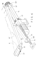
- FIG. 6 is a fragmentary perspective view of the turning mechanism for a patient confined to a bed according to the present invention.
- a turning mechanism for a patient confined to a bed includes a power source 1 , a first and a second movable frames 5 , 4 , and a first and a second adjusting members.
- the power source 1 includes a left reduction gear motor 11 , and a right reduction gear motor 12 .
- the motors 11 , 12 are fixedly disposed under a bed 7 or other proper places.
- Each of the reduction gear motors 11 , 12 has a main toothed wheel 13 connected to a shaft thereof.
- the movable frame 4 includes an elongated rod portion 41 , and two transverse rod portions 42 , 42 , which are connected to two ends of the elongated rod portion 41 at upper ends thereof.
- the movable frame 5 includes an elongated rod portion 51 , and two transverse rod portions 52 , 52 , which are connected to two ends of the elongated rod portion 51 at upper ends thereof.
- Each of the transverse rod portions 42 , 52 has a pair of holed connecting ears 43 , 53 sticking down from a middle portion thereof.
- each of the transverse rod portions 42 , 52 has a pivotal hole (not numbered) at a lower end thereof.
- the first, and the second adjusting members includes two propping rods 25 , 25 , and 35 , 35 , two transverse transmission shafts 2 , 2 , and 3 , 3 , a drive chain 14 , and 14 , a synchronizing chain 28 , and 38 .
- Each of the transverse transmission shafts 2 , 2 , and 3 , 3 has a threaded action section 23 ( 33 ) extending from one end to the other end.
- a first one of the transmission shafts 2 , 2 of the first adjusting member has a first toothed wheel 26 and a second toothed wheel 27 joined to a second end thereof, which is opposite to the first end, while a second one of the transmission shafts 2 , 2 has toothed wheel at the first end.
- a first one of the transmission shafts 3 , 3 of the second adjusting member has a first toothed wheel 36 and a second toothed wheel 37 joined to a second end thereof, which is opposite to the first end, while a second one of the transmission shafts 3 , 3 has toothed wheel at the first end.
- the first and the second transverse transmission shafts 2 , 2 are disposed at respective ends of the bed 7 , and turnably supported with support bases 21 at the first end, which have bearings for the first ends to be joined to, and are joined to bearings (not shown) fitted to shaft sleeves 22 at the second end.
- the first and the second transverse transmission shafts 3 , 3 of the second adjusting member are disposed at respective ends of the bed 7 , and turnably supported with support bases 31 at the first end, which have bearings for the first ends to be joined to, and are joined to bearings (not shown) fitted to shaft sleeves 32 at the second end.
- each of the shaft sleeves 22 , 32 of the transmission shafts 2 , 3 has a pair of upwards sticking connecting ears 221 , 321 , which have pivotal holes (not numbered).
- each of the transverse transmission shafts 2 , 2 , 3 , 3 has a moving base 24 , 34 screwed onto the threaded action section 23 , 33 thereof.
- Each of the moving bases 24 , 34 has a pair of holed connecting ears 241 , 341 sticking up from it.
- the drive chains 14 , 14 of the first and the second adjusting members are passed over the main toothed wheels 13 , 13 of the reduction gear motors 11 , 12 , and the second toothed wheels 27 , 37 so that the motors 11 , 12 can effect rotary movement of the transmission shafts 2 , 3 when they are in action.
- the synchronizing chains 28 , 38 of the first and the second adjusting members are passed over the first toothed wheels 26 , 36 , and the toothed wheels of the second transverse transmission shafts so that the motors 11 , 12 can effect rotary movement of the second transverse shafts when they are in action.
- first and the second movable frames 5 , 4 are pivotally connected to the upwards sticking connecting ears 221 , 321 of the shaft sleeves 22 , 32 respectively with the transverse rod portions 52 , 52 , 42 , 42 thereof being inserted between corresponding pairs of connecting ears 221 , 321 , and with pivotal axles (not numbered) being passed through the pivotal holes of the connecting ears 221 , 321 and the pivotal holes of the transverse rod portions 52 , 52 , 42 , 42 ; thus, the elongated rod portions 51 , 41 of the movable frames 5 , 4 , are positioned above opposite long sides of the bed 7 when the frames 5 , 4 , are positioned horizontal above the bed 7 .
- the propping rods 25 , 35 are pivotally connected to respective pairs of downwards-sticking holed connecting ears 53 , 43 of the middles of the transverse rod portions 52 , 42 at the upper ends thereof, and pivotally connected to respective pairs of holed connecting ears 241 , 341 of the moving bases 24 , 34 .
- a sheet 6 is provided; each of two long sides of the sheet 6 has two connecting portions 62 , 62 , and zippers 61 , 61 joined to the edges of the connecting portions 62 , 62 .
- the sheet 6 can be easily connected to the elongated rod portions 41 , 51 of the movable frames 4 , 5 with the connecting portions 62 , 62 being passed around the elongated rod portions 41 , 51 , and with the zippers 61 being connected to each other.
- a mattress 71 is disposed under the sheet 6 .
- the right reduction gear motor 11 is activated for both the transmission shafts 2 , 2 of the first adjusting member to turn, and in turn, the moving bases 24 move along the threaded action sections of both the transmission shafts 2 , 2 to the middles of the shafts 2 .
- the propping rods 25 of the first adjusting member prop up the transverse rod portions 52 , 52 of the movable frame 5 to a tilted position.
- the motors 11 , 12 are activated so that the movable frame 5 is pivoted to the horizontal position, and the movable frame 4 is propped up to a tilted position.
- the turning mechanism for a patient confined to a bed has desirable features as following:
- the present turning mechanism can be regarded as an improvement on those conventional ones that can only turn a patient to either a left or a right side rest position.
- the reduction gear motors provide the patient with slow and gentle turning movement, and can work together with the sheet to exert uniform force on the patient's body in turning movement. Thus, the patient won't suffer from a turning service, which is delivered manually, and would cause too much uncomfortable pressure on small portions of the patient's body.
- the elongated rod portions of both the movable frames can be raised a short distance from the bed so that the sheet sinks slightly for preventing the patient from falling off. Therefore, the present turning mechanism for a patient is safe to use.
- the normal side rails of bed can also be applied for double safety.
- the sheet is equipped with zippers for connection with the elongated rod portions of both the movable frames, it can be easily removed from the present turning mechanism for cleaning.
Abstract
Description
Claims (10)
Applications Claiming Priority (3)
| Application Number | Priority Date | Filing Date | Title |
|---|---|---|---|
| TW090132668 | 2001-12-28 | ||
| TW90132668 | 2001-12-28 | ||
| TW90132668A | 2001-12-28 |
Publications (2)
| Publication Number | Publication Date |
|---|---|
| US20030121098A1 US20030121098A1 (en) | 2003-07-03 |
| US6668396B2 true US6668396B2 (en) | 2003-12-30 |
Family
ID=21680066
Family Applications (1)
| Application Number | Title | Priority Date | Filing Date |
|---|---|---|---|
| US10/322,548 Expired - Fee Related US6668396B2 (en) | 2001-12-28 | 2002-12-19 | Turning mechanism for a patient confined to a bed |
Country Status (1)
| Country | Link |
|---|---|
| US (1) | US6668396B2 (en) |
Cited By (37)
| Publication number | Priority date | Publication date | Assignee | Title |
|---|---|---|---|---|
| US20050155149A1 (en) * | 2002-05-17 | 2005-07-21 | Pedersen Flemming B. | Device and bed for turning horizontally lying persons |
| US20070006388A1 (en) * | 2005-07-07 | 2007-01-11 | Townsend Bobie K | Inflatable device for turning people on their side and back again |
| US20070240260A1 (en) * | 2006-04-12 | 2007-10-18 | Elizabeth White | Patient positioning apparatus |
| US7343635B2 (en) | 2005-02-22 | 2008-03-18 | Jackson Roger P | Modular multi-articulated patient support system |
| US20080216232A1 (en) * | 2006-04-12 | 2008-09-11 | White Elizabeth A | Patient Repositioning System |
| US20080222811A1 (en) * | 2006-01-05 | 2008-09-18 | Jan Gilbert | Rotational Operating Table |
| US7434278B2 (en) | 2005-06-29 | 2008-10-14 | Elizabeth Ann White | Apparatus for patient mobility |
| US20080301873A1 (en) * | 2005-06-29 | 2008-12-11 | White Elizabeth A | Patient Positioning apparatus |
| US20100313353A1 (en) * | 2009-06-12 | 2010-12-16 | Bedlab, Llc | Stretcher Accessory for Turning a Patient |
| US9180062B2 (en) | 2005-02-22 | 2015-11-10 | Roger P. Jackson | Patient positioning support structure |
| US9186291B2 (en) | 2005-02-22 | 2015-11-17 | Roger P. Jackson | Patient positioning support structure with trunk translator |
| US9226865B2 (en) | 2005-02-22 | 2016-01-05 | Roger P. Jackson | Patient positioning support structure |
| US9265679B2 (en) | 2005-02-22 | 2016-02-23 | Roger P Jackson | Cantilevered patient positioning support structure |
| US9295433B2 (en) | 2005-02-22 | 2016-03-29 | Roger P. Jackson | Synchronized patient elevation and positioning apparatus for use with patient positioning support systems |
| US9301897B2 (en) | 2005-02-22 | 2016-04-05 | Roger P. Jackson | Patient positioning support structure |
| US9308145B2 (en) | 2005-02-22 | 2016-04-12 | Roger P. Jackson | Patient positioning support structure |
| US9339429B1 (en) | 2013-09-24 | 2016-05-17 | Lynne Eland-Rodriguez | Body transfer assembly |
| US9339430B2 (en) | 2006-05-05 | 2016-05-17 | Roger P. Jackson | Patient positioning support apparatus with virtual pivot-shift pelvic pads, upper body stabilization and fail-safe table attachment mechanism |
| US9358170B2 (en) | 2007-10-22 | 2016-06-07 | Roger P Jackson | Surgery table apparatus |
| US9402775B2 (en) | 2014-07-07 | 2016-08-02 | Roger P. Jackson | Single and dual column patient positioning and support structure |
| US9468576B2 (en) | 2005-02-22 | 2016-10-18 | Roger P. Jackson | Patient support apparatus with body slide position digitally coordinated with hinge angle |
| US20160346148A1 (en) * | 2012-02-07 | 2016-12-01 | Roger P. Jackson | Fail-safe release mechanism for use with patient positioning support apparati |
| US9549863B2 (en) | 2014-07-07 | 2017-01-24 | Roger P. Jackson | Surgical table with pivoting and translating hinge |
| US9642760B2 (en) | 2006-05-05 | 2017-05-09 | Roger P. Jackson | Patient positioning support apparatus with virtual pivot-shift pelvic pads, upper body stabilization and fail-safe table attachment mechanism |
| US9744087B2 (en) | 2005-02-22 | 2017-08-29 | Roger P. Jackson | Patient support apparatus with body slide position digitally coordinated with hinge angle |
| US9849054B2 (en) | 2005-02-22 | 2017-12-26 | Roger P. Jackson | Patient positioning support structure |
| US9968503B2 (en) | 2012-04-16 | 2018-05-15 | Allen Medical Systems, Inc. | Dual column surgical table having a single-handle unlock for table rotation |
| US10363189B2 (en) | 2015-10-23 | 2019-07-30 | Allen Medical Systems, Inc. | Surgical patient support for accommodating lateral-to-prone patient positioning |
| US10492973B2 (en) | 2015-01-05 | 2019-12-03 | Allen Medical Systems, Inc. | Dual modality prone spine patient support apparatuses |
| US10548793B2 (en) | 2016-06-14 | 2020-02-04 | Allen Medical Systems, Inc. | Pinless loading for spine table |
| US10561559B2 (en) | 2015-10-23 | 2020-02-18 | Allen Medical Systems, Inc. | Surgical patient support system and method for lateral-to-prone support of a patient during spine surgery |
| US10857054B2 (en) | 2015-11-13 | 2020-12-08 | Allen Medical Systems, Inc. | Person support apparatuses for subject repositioning |
| US10869798B2 (en) | 2006-05-05 | 2020-12-22 | Warsaw Orthopedic, Inc. | Patient positioning support apparatus with virtual pivot-shift pelvic pads, upper body stabilization and fail-safe table attachment mechanism |
| US11051770B2 (en) | 2005-02-22 | 2021-07-06 | Warsaw Orthopedic, Inc. | Patient positioning support structure |
| US11202731B2 (en) | 2018-02-28 | 2021-12-21 | Allen Medical Systems, Inc. | Surgical patient support and methods thereof |
| US11213448B2 (en) | 2017-07-31 | 2022-01-04 | Allen Medical Systems, Inc. | Rotation lockout for surgical support |
| US11471354B2 (en) | 2018-08-30 | 2022-10-18 | Allen Medical Systems, Inc. | Patient support with selectable pivot |
Families Citing this family (9)
| Publication number | Priority date | Publication date | Assignee | Title |
|---|---|---|---|---|
| US7237286B1 (en) * | 2006-01-20 | 2007-07-03 | Kim Willie W | Articulating bed |
| US7845034B2 (en) * | 2007-09-21 | 2010-12-07 | Kim Willie W | Articulating bed and method of operating the same |
| US8635725B2 (en) | 2008-10-28 | 2014-01-28 | Tony Y. Tannoury | Prone and laterally angled surgical device and method |
| DE102010032719A1 (en) * | 2010-07-23 | 2012-01-26 | Aacurat Gmbh | Actuating device for a turning device intended for the movement of patients with diseased lungs |
| DE102013106388B3 (en) * | 2013-06-19 | 2014-10-09 | Limoss Gmbh & Co. Kg | Adjustment mechanism for adjusting movable furniture parts |
| DK178222B1 (en) * | 2014-12-03 | 2015-08-31 | Gdv Technology Aps | New bed system that can be attached to a hospital bed |
| ES2562263B1 (en) * | 2015-10-20 | 2016-12-07 | Tomás FERNÁNDEZ LORENZO | Dump bed for people with disabilities |
| US10378697B2 (en) * | 2017-03-22 | 2019-08-13 | Hybrid Research Company Limited | Portable carbon dioxide adapter system |
| CN112618207A (en) * | 2021-02-18 | 2021-04-09 | 安徽医科大学第一附属医院 | Be used for old nursing turning-over device |
Citations (3)
| Publication number | Priority date | Publication date | Assignee | Title |
|---|---|---|---|---|
| US4654903A (en) * | 1985-05-07 | 1987-04-07 | Nova Technologies, Inc. | Bedsore prevention device in an invalid bed arrangement |
| US4819282A (en) * | 1987-12-07 | 1989-04-11 | Med-Ex Diagnostics Of Canada Inc. | Tilting mechanism for use with infant bassinette |
| US4856129A (en) * | 1986-08-22 | 1989-08-15 | Butler Wilbur T | Tiltable bed frame assembly |
-
2002
- 2002-12-19 US US10/322,548 patent/US6668396B2/en not_active Expired - Fee Related
Patent Citations (3)
| Publication number | Priority date | Publication date | Assignee | Title |
|---|---|---|---|---|
| US4654903A (en) * | 1985-05-07 | 1987-04-07 | Nova Technologies, Inc. | Bedsore prevention device in an invalid bed arrangement |
| US4856129A (en) * | 1986-08-22 | 1989-08-15 | Butler Wilbur T | Tiltable bed frame assembly |
| US4819282A (en) * | 1987-12-07 | 1989-04-11 | Med-Ex Diagnostics Of Canada Inc. | Tilting mechanism for use with infant bassinette |
Cited By (84)
| Publication number | Priority date | Publication date | Assignee | Title |
|---|---|---|---|---|
| US20050155149A1 (en) * | 2002-05-17 | 2005-07-21 | Pedersen Flemming B. | Device and bed for turning horizontally lying persons |
| US9226865B2 (en) | 2005-02-22 | 2016-01-05 | Roger P. Jackson | Patient positioning support structure |
| US9610206B2 (en) | 2005-02-22 | 2017-04-04 | Roger P. Jackson | Patient positioning support structure |
| US7343635B2 (en) | 2005-02-22 | 2008-03-18 | Jackson Roger P | Modular multi-articulated patient support system |
| US9744087B2 (en) | 2005-02-22 | 2017-08-29 | Roger P. Jackson | Patient support apparatus with body slide position digitally coordinated with hinge angle |
| US9289342B2 (en) | 2005-02-22 | 2016-03-22 | Roger P. Jackson | Patient positioning support structure |
| US9757300B2 (en) | 2005-02-22 | 2017-09-12 | Roger P Jackson | Patient positioning support structure |
| US9849054B2 (en) | 2005-02-22 | 2017-12-26 | Roger P. Jackson | Patient positioning support structure |
| US10500114B2 (en) | 2005-02-22 | 2019-12-10 | Warsaw Orthopedic, Inc. | Synchronized patient elevation and positioning apparatus for use with patient positioning support systems |
| US9265679B2 (en) | 2005-02-22 | 2016-02-23 | Roger P Jackson | Cantilevered patient positioning support structure |
| US9510987B2 (en) | 2005-02-22 | 2016-12-06 | Roger P. Jackson | Patient positioning support structure with trunk translator |
| US11547622B2 (en) | 2005-02-22 | 2023-01-10 | Warsaw Orthopedic, Inc. | Synchronized patient elevation and positioning apparatus for use with patient positioning support systems |
| US10695252B2 (en) | 2005-02-22 | 2020-06-30 | Warsaw Orthopedic, Inc. | Patient positioning support structure |
| US9180062B2 (en) | 2005-02-22 | 2015-11-10 | Roger P. Jackson | Patient positioning support structure |
| US9186291B2 (en) | 2005-02-22 | 2015-11-17 | Roger P. Jackson | Patient positioning support structure with trunk translator |
| US9198817B2 (en) | 2005-02-22 | 2015-12-01 | Roger P. Jackson | Patient positioning support structure |
| US9205013B2 (en) | 2005-02-22 | 2015-12-08 | Roger P. Jackson | Patient positioning support structure |
| US9211223B2 (en) | 2005-02-22 | 2015-12-15 | Roger P. Jackson | Patient positioning support structure |
| US9636266B2 (en) | 2005-02-22 | 2017-05-02 | Roger P. Jackson | Synchronized patient elevation and positioning apparatus for use with patient positioning support systems |
| US11679051B2 (en) | 2005-02-22 | 2023-06-20 | Warsaw Orthopedic, Inc. | Patient positioning support structure |
| US9504622B2 (en) | 2005-02-22 | 2016-11-29 | Roger P. Jackson | Patient positioning support structure with trunk translator |
| US9468576B2 (en) | 2005-02-22 | 2016-10-18 | Roger P. Jackson | Patient support apparatus with body slide position digitally coordinated with hinge angle |
| US9301897B2 (en) | 2005-02-22 | 2016-04-05 | Roger P. Jackson | Patient positioning support structure |
| US9308145B2 (en) | 2005-02-22 | 2016-04-12 | Roger P. Jackson | Patient positioning support structure |
| US11051770B2 (en) | 2005-02-22 | 2021-07-06 | Warsaw Orthopedic, Inc. | Patient positioning support structure |
| US10881566B2 (en) | 2005-02-22 | 2021-01-05 | Warsaw Orthopedic, Inc. | Patient support apparatus with body slide position digitally coordinated with hinge angle |
| US9295433B2 (en) | 2005-02-22 | 2016-03-29 | Roger P. Jackson | Synchronized patient elevation and positioning apparatus for use with patient positioning support systems |
| US9364380B2 (en) | 2005-02-22 | 2016-06-14 | Roger P Jackson | Patient positioning support structure |
| US10835438B2 (en) | 2005-02-22 | 2020-11-17 | Warsaw Orthopedic, Inc. | Modular multi-articulated patient support system |
| US9456945B2 (en) | 2005-02-22 | 2016-10-04 | Roger P. Jackson | Patient positioning support structure |
| US20080301873A1 (en) * | 2005-06-29 | 2008-12-11 | White Elizabeth A | Patient Positioning apparatus |
| US7434278B2 (en) | 2005-06-29 | 2008-10-14 | Elizabeth Ann White | Apparatus for patient mobility |
| US20070006388A1 (en) * | 2005-07-07 | 2007-01-11 | Townsend Bobie K | Inflatable device for turning people on their side and back again |
| US7464422B2 (en) | 2005-07-07 | 2008-12-16 | Bobie Kenneth Townsend | Inflatable device for turning people on their side and back again |
| US8042208B2 (en) * | 2006-01-05 | 2011-10-25 | Jan Gilbert | Rotational operating table |
| US20080222811A1 (en) * | 2006-01-05 | 2008-09-18 | Jan Gilbert | Rotational Operating Table |
| US20070240260A1 (en) * | 2006-04-12 | 2007-10-18 | Elizabeth White | Patient positioning apparatus |
| US8407831B2 (en) | 2006-04-12 | 2013-04-02 | Ergonurse, Inc. | Patient positioning apparatus |
| US20080216232A1 (en) * | 2006-04-12 | 2008-09-11 | White Elizabeth A | Patient Repositioning System |
| US10869798B2 (en) | 2006-05-05 | 2020-12-22 | Warsaw Orthopedic, Inc. | Patient positioning support apparatus with virtual pivot-shift pelvic pads, upper body stabilization and fail-safe table attachment mechanism |
| US9339430B2 (en) | 2006-05-05 | 2016-05-17 | Roger P. Jackson | Patient positioning support apparatus with virtual pivot-shift pelvic pads, upper body stabilization and fail-safe table attachment mechanism |
| US9642760B2 (en) | 2006-05-05 | 2017-05-09 | Roger P. Jackson | Patient positioning support apparatus with virtual pivot-shift pelvic pads, upper body stabilization and fail-safe table attachment mechanism |
| US11464697B2 (en) | 2006-05-05 | 2022-10-11 | Warsaw Orthopedic, Inc. | Patient positioning support apparatus with virtual pivot-shift pelvic pads, upper body stabilization and fail-safe table attachment mechanism |
| US11918518B2 (en) | 2006-05-05 | 2024-03-05 | Warsaw Orthopedic, Inc. | Patient positioning support apparatus with fail-safe connector attachment mechanism |
| US9744089B2 (en) | 2007-10-22 | 2017-08-29 | Roger P. Jackson | Surgery table apparatus |
| US9358170B2 (en) | 2007-10-22 | 2016-06-07 | Roger P Jackson | Surgery table apparatus |
| US8261380B2 (en) | 2009-06-12 | 2012-09-11 | Bedlab, Llc | Stretcher accessory for turning a patient |
| US20100313353A1 (en) * | 2009-06-12 | 2010-12-16 | Bedlab, Llc | Stretcher Accessory for Turning a Patient |
| US11110022B2 (en) | 2010-06-21 | 2021-09-07 | Warsaw Orthopedic, Inc | Patient positioning support structure with trunk translator |
| US9937094B2 (en) | 2010-06-21 | 2018-04-10 | Roger P. Jackson | Patient positioning support structure with trunk translator |
| US10531998B2 (en) | 2010-06-21 | 2020-01-14 | Warsaw Orthopedic, Inc. | Patient positioning support structure with trunk translator |
| US10729607B2 (en) | 2010-06-21 | 2020-08-04 | Warsaw Orthopedic, Inc. | Patient positioning support structure with trunk translator |
| US11435776B2 (en) | 2012-02-07 | 2022-09-06 | Warsaw Orthopedic, Inc. | Fail-safe release mechanism for use with patient positioning support apparati |
| US9687399B2 (en) * | 2012-02-07 | 2017-06-27 | Roger P. Jackson | Fail-safe release mechanism for use with patient positioning support apparati |
| US11874685B2 (en) | 2012-02-07 | 2024-01-16 | Warsaw Orthopedic, Inc. | Fail-safe release mechanisms for use with interchangeable patient positioning support structures |
| US9889054B2 (en) | 2012-02-07 | 2018-02-13 | Warsaw Orthopedic, Inc. | Fail-safe release mechanism for use with patient positioning support apparati |
| US9877883B2 (en) * | 2012-02-07 | 2018-01-30 | Warsaw Orthopedic, Inc. | Fail-safe release mechanism for use with patient positioning support apparati |
| US9561145B2 (en) | 2012-02-07 | 2017-02-07 | Roger P. Jackson | Fail-safe release mechanism for use with patient positioning support apparati |
| US9572734B2 (en) * | 2012-02-07 | 2017-02-21 | Roger P. Jackson | Fail-safe release mechanism for use with patient positioning support apparati |
| US20160346148A1 (en) * | 2012-02-07 | 2016-12-01 | Roger P. Jackson | Fail-safe release mechanism for use with patient positioning support apparati |
| US10993864B2 (en) | 2012-04-16 | 2021-05-04 | Allen Medical Systems, Inc. | Bracket attachment apparatus for dual column surgical table |
| US11938065B2 (en) | 2012-04-16 | 2024-03-26 | Allen Medical Systems, Inc. | Table top to bracket coupling apparatus for spine surgery table |
| US11452657B2 (en) | 2012-04-16 | 2022-09-27 | Allen Medical Systems, Inc. | Dual column surgical table having a single-handle unlock for table rotation |
| US9968503B2 (en) | 2012-04-16 | 2018-05-15 | Allen Medical Systems, Inc. | Dual column surgical table having a single-handle unlock for table rotation |
| US9339429B1 (en) | 2013-09-24 | 2016-05-17 | Lynne Eland-Rodriguez | Body transfer assembly |
| US9402775B2 (en) | 2014-07-07 | 2016-08-02 | Roger P. Jackson | Single and dual column patient positioning and support structure |
| US10667975B2 (en) | 2014-07-07 | 2020-06-02 | Warsaw Orthopedic, Inc. | Single and dual column patient positioning support structure |
| US9622928B2 (en) | 2014-07-07 | 2017-04-18 | Roger P. Jackson | Radiolucent hinge for a surgical table |
| US9549863B2 (en) | 2014-07-07 | 2017-01-24 | Roger P. Jackson | Surgical table with pivoting and translating hinge |
| US9629766B2 (en) | 2014-07-07 | 2017-04-25 | Roger P. Jackson | Surgical table with patient support having flexible inner frame supported on rigid outer frame |
| US11464698B2 (en) | 2014-07-07 | 2022-10-11 | Warsaw Orthopedic, Inc. | Single and dual column patient positioning support structure |
| US10492973B2 (en) | 2015-01-05 | 2019-12-03 | Allen Medical Systems, Inc. | Dual modality prone spine patient support apparatuses |
| US10363189B2 (en) | 2015-10-23 | 2019-07-30 | Allen Medical Systems, Inc. | Surgical patient support for accommodating lateral-to-prone patient positioning |
| US11096853B2 (en) | 2015-10-23 | 2021-08-24 | Allen Medical Systems, Inc. | Surgical patient support for accommodating lateral-to-prone patient positioning |
| US10792207B2 (en) | 2015-10-23 | 2020-10-06 | Allen Medical Systems, Inc. | Lateral-to-prone spine surgery table |
| US10561559B2 (en) | 2015-10-23 | 2020-02-18 | Allen Medical Systems, Inc. | Surgical patient support system and method for lateral-to-prone support of a patient during spine surgery |
| US11642269B2 (en) | 2015-11-13 | 2023-05-09 | Allen Medical Systems, Inc. | Person support apparatuses for subject repositioning |
| US10857054B2 (en) | 2015-11-13 | 2020-12-08 | Allen Medical Systems, Inc. | Person support apparatuses for subject repositioning |
| US10548793B2 (en) | 2016-06-14 | 2020-02-04 | Allen Medical Systems, Inc. | Pinless loading for spine table |
| US11213448B2 (en) | 2017-07-31 | 2022-01-04 | Allen Medical Systems, Inc. | Rotation lockout for surgical support |
| US11554068B2 (en) | 2017-07-31 | 2023-01-17 | Allen Medical Systems, Inc. | Rotation lockout for surgical support |
| US11752055B2 (en) | 2017-07-31 | 2023-09-12 | Allen Medical Systems, Inc. | Rotation lockout for surgical support |
| US11202731B2 (en) | 2018-02-28 | 2021-12-21 | Allen Medical Systems, Inc. | Surgical patient support and methods thereof |
| US11471354B2 (en) | 2018-08-30 | 2022-10-18 | Allen Medical Systems, Inc. | Patient support with selectable pivot |
Also Published As
| Publication number | Publication date |
|---|---|
| US20030121098A1 (en) | 2003-07-03 |
Similar Documents
| Publication | Publication Date | Title |
|---|---|---|
| US6668396B2 (en) | Turning mechanism for a patient confined to a bed | |
| US6651281B1 (en) | Support assembly means | |
| US4530122A (en) | Patient weight reliever apparatus | |
| US9579243B2 (en) | Patient transfer device | |
| US3877421A (en) | Patient lift and exercise apparatus | |
| US4446587A (en) | Patient positioning device | |
| US3875598A (en) | Cradling and articulated bed | |
| JP7207635B2 (en) | Rolling over support device | |
| CN109316299A (en) | A kind of multifunctional wheelchair nursing bed | |
| EP3117815B1 (en) | Pull-type body turning aid | |
| WO2007055051A1 (en) | Bed for nursing care | |
| CN109589217A (en) | It is a kind of can Free Transform it is medical care bed | |
| CN209270138U (en) | A kind of multifunctional wheelchair nursing bed | |
| US2873456A (en) | Bed with invalid lift | |
| JP4320739B2 (en) | Assistance device | |
| KR200325738Y1 (en) | Hight Adjustment Apparatus of Simplicity Bed for Medical Examination | |
| CN2243280Y (en) | Self nursing bed | |
| JPH06209970A (en) | Lift for nursing | |
| CN211023686U (en) | Hip lifting machine | |
| CN220513038U (en) | Structure for assisting patient in turning over | |
| IT201800006222A1 (en) | Transport frame for a stretcher. | |
| TWI784891B (en) | Medical automatic turnover bed | |
| KR19990024131A (en) | Patient transfer device | |
| JP2000126232A (en) | Patient transfer device | |
| JPH07213561A (en) | Bed for medical care system, patient transportation system to be combined with bed, and both joint device and interlocking control device connecting bed with transportation system |
Legal Events
| Date | Code | Title | Description |
|---|---|---|---|
| AS | Assignment |
Owner name: SOUTHERN TAIWAN UNIVERSITY OF TECHNOLOGY, TAIWAN Free format text: ASSIGNMENT OF ASSIGNORS INTEREST;ASSIGNOR:WEI, CHING-HUA;REEL/FRAME:015521/0537 Effective date: 20041124 |
|
| FPAY | Fee payment |
Year of fee payment: 4 |
|
| FPAY | Fee payment |
Year of fee payment: 8 |
|
| REMI | Maintenance fee reminder mailed | ||
| LAPS | Lapse for failure to pay maintenance fees | ||
| LAPS | Lapse for failure to pay maintenance fees |
Free format text: PATENT EXPIRED FOR FAILURE TO PAY MAINTENANCE FEES (ORIGINAL EVENT CODE: EXP.); ENTITY STATUS OF PATENT OWNER: SMALL ENTITY |
|
| STCH | Information on status: patent discontinuation |
Free format text: PATENT EXPIRED DUE TO NONPAYMENT OF MAINTENANCE FEES UNDER 37 CFR 1.362 |
|
| FP | Lapsed due to failure to pay maintenance fee |
Effective date: 20151230 |