US6630253B1 - Organic electroluminescence device - Google Patents
Organic electroluminescence device Download PDFInfo
- Publication number
- US6630253B1 US6630253B1 US09/274,963 US27496399A US6630253B1 US 6630253 B1 US6630253 B1 US 6630253B1 US 27496399 A US27496399 A US 27496399A US 6630253 B1 US6630253 B1 US 6630253B1
- Authority
- US
- United States
- Prior art keywords
- groups
- substituted
- group
- unsubstituted
- phenanthroline
- Prior art date
- Legal status (The legal status is an assumption and is not a legal conclusion. Google has not performed a legal analysis and makes no representation as to the accuracy of the status listed.)
- Expired - Lifetime
Links
- 0 [1*]C1=C2N=C(C3=CC(O)=C(C4=NC5=C(*4)C([8*])=C([7*])C([6*])=C5[5*])C=C3O)*C2=C([4*])C([3*])=C1[2*] Chemical compound [1*]C1=C2N=C(C3=CC(O)=C(C4=NC5=C(*4)C([8*])=C([7*])C([6*])=C5[5*])C=C3O)*C2=C([4*])C([3*])=C1[2*] 0.000 description 8
- GETQZCLCWQTVFV-UHFFFAOYSA-N CN(C)C Chemical compound CN(C)C GETQZCLCWQTVFV-UHFFFAOYSA-N 0.000 description 2
- MUMVIYLVHVCYGI-UHFFFAOYSA-N CN(C)C(N(C)C)N(C)C Chemical compound CN(C)C(N(C)C)N(C)C MUMVIYLVHVCYGI-UHFFFAOYSA-N 0.000 description 2
- UYZWODKAWIMNPJ-UHFFFAOYSA-N CN(C)[Y]N(C)C Chemical compound CN(C)[Y]N(C)C UYZWODKAWIMNPJ-UHFFFAOYSA-N 0.000 description 2
- ZQFGMDNHQLFZIK-UHFFFAOYSA-C C1=CC2=CC=CN3=C2C(=C1)O[Al]312(OC3=CC=CC4=CC=CN1=C43)O/C1=C/C=C\C3=CC=CN2=C31.C1=CC2=CC=CN3=C2C(=C1)O[Ga]312(OC3=CC=CC4=CC=CN1=C43)O/C1=C/C=C\C3=CC=CN2=C31.C1=CC2=CC=CN3=C2C(=C1)O[Zn]31OC2=CC=CC3=CC=CN1=C32.C1=CC2=CN3=C4C(=CC=CC4=C2C=C1)O[Al]312(OC3=CC=CC4=C5=C/C=C\C=C5=CN1=C34)O/C1=C/C=C\C3=C4C=CC=CC4=CN2=C31 Chemical compound C1=CC2=CC=CN3=C2C(=C1)O[Al]312(OC3=CC=CC4=CC=CN1=C43)O/C1=C/C=C\C3=CC=CN2=C31.C1=CC2=CC=CN3=C2C(=C1)O[Ga]312(OC3=CC=CC4=CC=CN1=C43)O/C1=C/C=C\C3=CC=CN2=C31.C1=CC2=CC=CN3=C2C(=C1)O[Zn]31OC2=CC=CC3=CC=CN1=C32.C1=CC2=CN3=C4C(=CC=CC4=C2C=C1)O[Al]312(OC3=CC=CC4=C5=C/C=C\C=C5=CN1=C34)O/C1=C/C=C\C3=C4C=CC=CC4=CN2=C31 ZQFGMDNHQLFZIK-UHFFFAOYSA-C 0.000 description 1
- QPWYGVUEGWNHEX-YPCARLSDSA-D C1=CC=C(/C=C/C2=CC=C3C=CC=C4O[Zn]5(OC6=CC=CC7=CC=C(/C=C/C8=CC=CC=C8)N5=C76)N2=C34)C=C1.C1=CC=C(C2=CC=C(/C=C/C3=CC=C4C=CC=C5O[Zn]6(OC7=CC=CC8=CC=C(/C=C/C9=CC=C(C%10=CC=CC=C%10)C=C9)N6=C87)N3=C45)C=C2)C=C1.CC1=CC=C2C=CC=C3O[AlH]4(OC5=CC=C(C6=CC=CC=C6)C=C5)(O/C5=C/C=C\C6=CC=C(C)N4=C65)N1=C23.CC1=CC=C2C=CC=C3O[AlH]4(OC5=CC=CC=C5)(O/C5=C/C=C\C6=CC=C(C)N4=C65)N1=C23 Chemical compound C1=CC=C(/C=C/C2=CC=C3C=CC=C4O[Zn]5(OC6=CC=CC7=CC=C(/C=C/C8=CC=CC=C8)N5=C76)N2=C34)C=C1.C1=CC=C(C2=CC=C(/C=C/C3=CC=C4C=CC=C5O[Zn]6(OC7=CC=CC8=CC=C(/C=C/C9=CC=C(C%10=CC=CC=C%10)C=C9)N6=C87)N3=C45)C=C2)C=C1.CC1=CC=C2C=CC=C3O[AlH]4(OC5=CC=C(C6=CC=CC=C6)C=C5)(O/C5=C/C=C\C6=CC=C(C)N4=C65)N1=C23.CC1=CC=C2C=CC=C3O[AlH]4(OC5=CC=CC=C5)(O/C5=C/C=C\C6=CC=C(C)N4=C65)N1=C23 QPWYGVUEGWNHEX-YPCARLSDSA-D 0.000 description 1
- FSQKMHDJCCHLIR-UHFFFAOYSA-N C1=CC=C(C2=CC=C(N(C3=CC=C(N(C4=CC=CC=C4)C4=CC=CC=C4)C=C3)C3=CC=C(N(C4=CC=CC=C4)C4=CC=CC=C4)C=C3)C=C2)C=C1.CC1=CC(N(C2=CC=CC=C2)C2=CC=C(N(C3=CC=C(N(C4=CC=CC=C4)C4=CC=CC(C)=C4)C=C3)C3=CC=C(N(C4=CC=CC=C4)C4=CC=CC(C)=C4)C=C3)C=C2)=CC=C1 Chemical compound C1=CC=C(C2=CC=C(N(C3=CC=C(N(C4=CC=CC=C4)C4=CC=CC=C4)C=C3)C3=CC=C(N(C4=CC=CC=C4)C4=CC=CC=C4)C=C3)C=C2)C=C1.CC1=CC(N(C2=CC=CC=C2)C2=CC=C(N(C3=CC=C(N(C4=CC=CC=C4)C4=CC=CC(C)=C4)C=C3)C3=CC=C(N(C4=CC=CC=C4)C4=CC=CC(C)=C4)C=C3)C=C2)=CC=C1 FSQKMHDJCCHLIR-UHFFFAOYSA-N 0.000 description 1
- FOKIWLUICDLPCN-UHFFFAOYSA-N C1=CC=C(C2=CC=C(N(C3=CC=CC=C3)C3=CC=CC=C3)C=C2)C=C1.C1=CC=C(N(C2=CC3=C(C=CC=C3)C=C2)C2=CC3=C(C=CC=C3)C=C2)C=C1.C1=CC=C(N(C2=CC=CC=C2)C2=C3=CC=CC=C3=CC=C2)C=C1.C1=CC=C(N(C2=CC=CC=C2)C2=CC3=C(C=CC=C3)C=C2)C=C1.C1=CC=C(N(C2=CC=CC=C2)C2=CC=CC=C2)C=C1 Chemical compound C1=CC=C(C2=CC=C(N(C3=CC=CC=C3)C3=CC=CC=C3)C=C2)C=C1.C1=CC=C(N(C2=CC3=C(C=CC=C3)C=C2)C2=CC3=C(C=CC=C3)C=C2)C=C1.C1=CC=C(N(C2=CC=CC=C2)C2=C3=CC=CC=C3=CC=C2)C=C1.C1=CC=C(N(C2=CC=CC=C2)C2=CC3=C(C=CC=C3)C=C2)C=C1.C1=CC=C(N(C2=CC=CC=C2)C2=CC=CC=C2)C=C1 FOKIWLUICDLPCN-UHFFFAOYSA-N 0.000 description 1
- YDGKEVLIQRYHCK-UHFFFAOYSA-N C1=CC=C(N(C2=CC=C(C3=CC=C(N(C4=CC=CC=C4)C4=C5C=CC=CC5=CC=C4)C=C3)C=C2)C2=CC=CC3=C2C=CC=C3)C=C1.CC1=CC(N(C2=CC=C(N(C3=CC=C(C4=CC=CC=C4)C=C3)C3=CC=C(N(C4=CC=CC(C)=C4)C4=CC=CC(C)=C4)C=C3)C=C2)C2=CC=CC(C)=C2)=CC=C1.CC1=CC=C(N(C2=CC=C(C)C=C2)C2=CC=C(C3(C4=CC=C(N(C5=CC=C(C)C=C5)C5=CC=C(C)C=C5)C=C4)CCCCC3)C=C2)C=C1.CC1=CC=C(N(C2=CC=CC=C2)C2=CC=C(C3=CC=C(N(C4=CC=CC=C4)C4=CC=C(C)C=C4)C=C3)C=C2)C=C1 Chemical compound C1=CC=C(N(C2=CC=C(C3=CC=C(N(C4=CC=CC=C4)C4=C5C=CC=CC5=CC=C4)C=C3)C=C2)C2=CC=CC3=C2C=CC=C3)C=C1.CC1=CC(N(C2=CC=C(N(C3=CC=C(C4=CC=CC=C4)C=C3)C3=CC=C(N(C4=CC=CC(C)=C4)C4=CC=CC(C)=C4)C=C3)C=C2)C2=CC=CC(C)=C2)=CC=C1.CC1=CC=C(N(C2=CC=C(C)C=C2)C2=CC=C(C3(C4=CC=C(N(C5=CC=C(C)C=C5)C5=CC=C(C)C=C5)C=C4)CCCCC3)C=C2)C=C1.CC1=CC=C(N(C2=CC=CC=C2)C2=CC=C(C3=CC=C(N(C4=CC=CC=C4)C4=CC=C(C)C=C4)C=C3)C=C2)C=C1 YDGKEVLIQRYHCK-UHFFFAOYSA-N 0.000 description 1
- KKCKEVMGEOWMIQ-UHFFFAOYSA-N C1=CC=C(N(C2=CC=CC=C2)C2=CC3=C(C=CC=N3)C=C2)C=C1.CC1=CC=C(N(C2=CC=C(C)C=C2)C2=C3=CC=CC=C3=C(C3=C4=CC=CC=C4=CC4=C3C=CC=C4)C3=C2C=CC=C3)C=C1.CC1=CC=C(N(C2=CC=CC=C2)C2=CC=C(C)C=C2)C=C1 Chemical compound C1=CC=C(N(C2=CC=CC=C2)C2=CC3=C(C=CC=N3)C=C2)C=C1.CC1=CC=C(N(C2=CC=C(C)C=C2)C2=C3=CC=CC=C3=C(C3=C4=CC=CC=C4=CC4=C3C=CC=C4)C3=C2C=CC=C3)C=C1.CC1=CC=C(N(C2=CC=CC=C2)C2=CC=C(C)C=C2)C=C1 KKCKEVMGEOWMIQ-UHFFFAOYSA-N 0.000 description 1
- ZMUKVBRYCDPGOE-ZSGCCVJVSA-N C1=CC=C(N(C2=CC=CC=C2)C2=CC=C(C3=CC=C(N(C4=CC=CC=C4)C4=CC=CC=C4)C=C3)C=C2)C=C1.CC1=CC=C(/C=C/C2=CC=C(N(C3=CC=C(C)C=C3)C3=CC=C(N(C4=CC=C(C)C=C4)C4=CC=C(/C=C/C5=CC=C(C)C=C5)C=C4)C4=C3C=CC=C4)C=C2)C=C1.CC1=CC=C(N(C2=CC=C(C)C=C2)C2=C3C=CC=CC3=C(C3=C4=CC=CC=C4=C(N(C4=CC=C(C)C=C4)C4=CC=C(C)C=C4)C4=CC=CC=C43)C3=C2=CC=CC3)C=C1.CC1=CC=C(N(C2=CC=C(C3=CC=C(N(C4=CC=C(C)C=C4)C4=C5C=CC=CC5CC=C4)C=C3)C=C2)C2=C3C=CC=CC3=CC=C2)C=C1 Chemical compound C1=CC=C(N(C2=CC=CC=C2)C2=CC=C(C3=CC=C(N(C4=CC=CC=C4)C4=CC=CC=C4)C=C3)C=C2)C=C1.CC1=CC=C(/C=C/C2=CC=C(N(C3=CC=C(C)C=C3)C3=CC=C(N(C4=CC=C(C)C=C4)C4=CC=C(/C=C/C5=CC=C(C)C=C5)C=C4)C4=C3C=CC=C4)C=C2)C=C1.CC1=CC=C(N(C2=CC=C(C)C=C2)C2=C3C=CC=CC3=C(C3=C4=CC=CC=C4=C(N(C4=CC=C(C)C=C4)C4=CC=C(C)C=C4)C4=CC=CC=C43)C3=C2=CC=CC3)C=C1.CC1=CC=C(N(C2=CC=C(C3=CC=C(N(C4=CC=C(C)C=C4)C4=C5C=CC=CC5CC=C4)C=C3)C=C2)C2=C3C=CC=CC3=CC=C2)C=C1 ZMUKVBRYCDPGOE-ZSGCCVJVSA-N 0.000 description 1
- BTQKXFLSCGJEMI-UHFFFAOYSA-N CC(C)(C)C1=CC=C(C2=NN=C(C3=CC=C(C4=CC=CC=C4)C=C3)N2C2=CC=CC=C2)C=C1.CC(C)(C)C1=CC=C(C2=NN=C(C3=CC=C(C4=CC=CC=C4)C=C3)O2)C=C1.CC(C)(C)C1=CC=C(C2=NN=C(C3=CC=CC(C4=NN=C(C5=CC=C(C(C)(C)C)C=C5)O4)=C3)O2)C=C1.CCC1=CC=C(N2C(C3=CC=C(C4=CC=CC=C4)C=C3)=NN=C2C2=CC=C(C(C)(C)C)C=C2)C=C1 Chemical compound CC(C)(C)C1=CC=C(C2=NN=C(C3=CC=C(C4=CC=CC=C4)C=C3)N2C2=CC=CC=C2)C=C1.CC(C)(C)C1=CC=C(C2=NN=C(C3=CC=C(C4=CC=CC=C4)C=C3)O2)C=C1.CC(C)(C)C1=CC=C(C2=NN=C(C3=CC=CC(C4=NN=C(C5=CC=C(C(C)(C)C)C=C5)O4)=C3)O2)C=C1.CCC1=CC=C(N2C(C3=CC=C(C4=CC=CC=C4)C=C3)=NN=C2C2=CC=C(C(C)(C)C)C=C2)C=C1 BTQKXFLSCGJEMI-UHFFFAOYSA-N 0.000 description 1
- XAAJXIKABGQDMY-UHFFFAOYSA-A CC1=CC(C)=C2C=CC=C3O[AlH]4(O[AlH]56(OC7=CC=CC8=C(C)C=C(C)N5=C78)OC5=CC=CC7=C(C)C=C(C)N6=C57)(OC5=CC=CC6=C(C)C=C(C)N4=C56)N1=C32.CC1=CC=C2C=CC=C3O[AlH]4(OC5=C6=CC=CC=C6=C(O[AlH]67(OC8=CC=CC9=CC=C(C)N6=C98)OC6=CC=CC8=CC=C(C)N7=C86)C=C5)(OC5=CC=CC6=CC=CN4=C65)N1=C23.CC1=CC=C2C=CC=C3O[AlH]4(OC5=CC=C(C6=CC=C(O[AlH]78(OC9=CC=CC%10=CC=C(C)N7=C%109)OC7=CC=CC9=CC=C(C)N8=C97)C=C6)C=C5)(OC5=CC=CC6=CC=C(C)N4=C65)N1=C23.CC1=CC=C2C=CC=C3O[AlH]4(OC5=CC=C(O[AlH]67(OC8=CC=CC9=CC=C(C)N6=C98)OC6=CC=CC8=CC=C(C)N7=C86)C=C5)(OC5=CC=CC6=CC=CN4=C65)N1=C23.CC1=CC=C2C=CC=C3O[AlH]4(O[AlH]56(OC7=CC=CC8=CC=C(C)N5=C87)OC5=CC=CC7=CC=C(C)N6=C75)(OC5=CC=CC6=CC=C(C)N4=C65)N1=C23 Chemical compound CC1=CC(C)=C2C=CC=C3O[AlH]4(O[AlH]56(OC7=CC=CC8=C(C)C=C(C)N5=C78)OC5=CC=CC7=C(C)C=C(C)N6=C57)(OC5=CC=CC6=C(C)C=C(C)N4=C56)N1=C32.CC1=CC=C2C=CC=C3O[AlH]4(OC5=C6=CC=CC=C6=C(O[AlH]67(OC8=CC=CC9=CC=C(C)N6=C98)OC6=CC=CC8=CC=C(C)N7=C86)C=C5)(OC5=CC=CC6=CC=CN4=C65)N1=C23.CC1=CC=C2C=CC=C3O[AlH]4(OC5=CC=C(C6=CC=C(O[AlH]78(OC9=CC=CC%10=CC=C(C)N7=C%109)OC7=CC=CC9=CC=C(C)N8=C97)C=C6)C=C5)(OC5=CC=CC6=CC=C(C)N4=C65)N1=C23.CC1=CC=C2C=CC=C3O[AlH]4(OC5=CC=C(O[AlH]67(OC8=CC=CC9=CC=C(C)N6=C98)OC6=CC=CC8=CC=C(C)N7=C86)C=C5)(OC5=CC=CC6=CC=CN4=C65)N1=C23.CC1=CC=C2C=CC=C3O[AlH]4(O[AlH]56(OC7=CC=CC8=CC=C(C)N5=C87)OC5=CC=CC7=CC=C(C)N6=C75)(OC5=CC=CC6=CC=C(C)N4=C65)N1=C23 XAAJXIKABGQDMY-UHFFFAOYSA-A 0.000 description 1
- MYDWEQSVMMPFNS-UHFFFAOYSA-N CC1=CC2=C(C=C1C)SC(C1=C(O)C=C(C3=NC4=CC(C)=C(C)C=C4S3)C(O)=C1)=N2.OC1=CC(C2=NC3=C(C=C4C=CC=CC4=C3)S2)=C(O)C=C1C1=NC2=CC3=CC=CC=C3C=C2S1.OC1=CC(C2=NC3=C(C=CC(C4=CC=CC=C4)=C3)S2)=C(O)C=C1C1=NC2=CC(C3=CC=CC=C3)=CC=C2S1 Chemical compound CC1=CC2=C(C=C1C)SC(C1=C(O)C=C(C3=NC4=CC(C)=C(C)C=C4S3)C(O)=C1)=N2.OC1=CC(C2=NC3=C(C=C4C=CC=CC4=C3)S2)=C(O)C=C1C1=NC2=CC3=CC=CC=C3C=C2S1.OC1=CC(C2=NC3=C(C=CC(C4=CC=CC=C4)=C3)S2)=C(O)C=C1C1=NC2=CC(C3=CC=CC=C3)=CC=C2S1 MYDWEQSVMMPFNS-UHFFFAOYSA-N 0.000 description 1
- YJCHPWQSYWBRSB-UHFFFAOYSA-N CC1=CC=C(N(C2=CC=C(C)C=C2)C2=CC(N(C3=CC=C(C)C=C3)C3=CC=C(C)C=C3)=CC(N(C3=CC=C(C)C=C3)C3=CC=C(C)C=C3)=C2)C=C1.CC1=CC=C(N(C2=CC=C(C)C=C2)C2=CC=C(N(C3=CC=C(N(C4=CC=C(C)C=C4)C4=CC=C(C)C=C4)C=C3)C3=CC=C(N(C4=CC=C(C)C=C4)C4=CC=C(C)C=C4)C=C3)C=C2)C=C1 Chemical compound CC1=CC=C(N(C2=CC=C(C)C=C2)C2=CC(N(C3=CC=C(C)C=C3)C3=CC=C(C)C=C3)=CC(N(C3=CC=C(C)C=C3)C3=CC=C(C)C=C3)=C2)C=C1.CC1=CC=C(N(C2=CC=C(C)C=C2)C2=CC=C(N(C3=CC=C(N(C4=CC=C(C)C=C4)C4=CC=C(C)C=C4)C=C3)C3=CC=C(N(C4=CC=C(C)C=C4)C4=CC=C(C)C=C4)C=C3)C=C2)C=C1 YJCHPWQSYWBRSB-UHFFFAOYSA-N 0.000 description 1
- QCTSQRBNGSHAFE-UHFFFAOYSA-K CC1=CC=C2C=CC=C3O[AlH2](OC4=CC=CC=C4)(OC4=CC=CC=C4)N1=C23 Chemical compound CC1=CC=C2C=CC=C3O[AlH2](OC4=CC=CC=C4)(OC4=CC=CC=C4)N1=C23 QCTSQRBNGSHAFE-UHFFFAOYSA-K 0.000 description 1
- HYQPMKZIBKEBJJ-UHFFFAOYSA-N CC1=CC=C2NC(C3=CC(O)=C(C4=NC5=C(C=CC(C)=C5)N4)C=C3O)=NC2=C1.CC1=CC=C2OC(C3=CC(O)=C(C4=NC5=C(C=CC(C)=C5)O4)C=C3O)=NC2=C1.O=[N+]([O-])C1=CC=CC2=C1OC(C1=C(O)C=C(C3=NC4=CC=CC([N+](=O)[O-])=C4O3)C(O)=C1)=N2.OC1=CC(C2=NC3=C(C=CC=C3)N2)=C(O)C=C1C1=NC2=CC=CC=C2N1.OC1=CC(C2=NC3=C(C=CC=C3)O2)=C(O)C=C1C1=NC2=CC=CC=C2O1.OC1=CC(C2=NC3=C(C=CC=C3)S2)=C(O)C=C1C1=NC2=CC=CC=C2S1.OC1=CC(C2=NC3=C(C=CC=C3Cl)N2)=C(O)C=C1C1=NC2=C(Cl)C=CC=C2N1 Chemical compound CC1=CC=C2NC(C3=CC(O)=C(C4=NC5=C(C=CC(C)=C5)N4)C=C3O)=NC2=C1.CC1=CC=C2OC(C3=CC(O)=C(C4=NC5=C(C=CC(C)=C5)O4)C=C3O)=NC2=C1.O=[N+]([O-])C1=CC=CC2=C1OC(C1=C(O)C=C(C3=NC4=CC=CC([N+](=O)[O-])=C4O3)C(O)=C1)=N2.OC1=CC(C2=NC3=C(C=CC=C3)N2)=C(O)C=C1C1=NC2=CC=CC=C2N1.OC1=CC(C2=NC3=C(C=CC=C3)O2)=C(O)C=C1C1=NC2=CC=CC=C2O1.OC1=CC(C2=NC3=C(C=CC=C3)S2)=C(O)C=C1C1=NC2=CC=CC=C2S1.OC1=CC(C2=NC3=C(C=CC=C3Cl)N2)=C(O)C=C1C1=NC2=C(Cl)C=CC=C2N1 HYQPMKZIBKEBJJ-UHFFFAOYSA-N 0.000 description 1
Images


Classifications
-
- C—CHEMISTRY; METALLURGY
- C09—DYES; PAINTS; POLISHES; NATURAL RESINS; ADHESIVES; COMPOSITIONS NOT OTHERWISE PROVIDED FOR; APPLICATIONS OF MATERIALS NOT OTHERWISE PROVIDED FOR
- C09K—MATERIALS FOR MISCELLANEOUS APPLICATIONS, NOT PROVIDED FOR ELSEWHERE
- C09K11/00—Luminescent, e.g. electroluminescent, chemiluminescent materials
- C09K11/06—Luminescent, e.g. electroluminescent, chemiluminescent materials containing organic luminescent materials
-
- H—ELECTRICITY
- H10—SEMICONDUCTOR DEVICES; ELECTRIC SOLID-STATE DEVICES NOT OTHERWISE PROVIDED FOR
- H10K—ORGANIC ELECTRIC SOLID-STATE DEVICES
- H10K85/00—Organic materials used in the body or electrodes of devices covered by this subclass
- H10K85/60—Organic compounds having low molecular weight
- H10K85/649—Aromatic compounds comprising a hetero atom
- H10K85/657—Polycyclic condensed heteroaromatic hydrocarbons
-
- C—CHEMISTRY; METALLURGY
- C09—DYES; PAINTS; POLISHES; NATURAL RESINS; ADHESIVES; COMPOSITIONS NOT OTHERWISE PROVIDED FOR; APPLICATIONS OF MATERIALS NOT OTHERWISE PROVIDED FOR
- C09K—MATERIALS FOR MISCELLANEOUS APPLICATIONS, NOT PROVIDED FOR ELSEWHERE
- C09K2211/00—Chemical nature of organic luminescent or tenebrescent compounds
- C09K2211/10—Non-macromolecular compounds
- C09K2211/1003—Carbocyclic compounds
- C09K2211/1014—Carbocyclic compounds bridged by heteroatoms, e.g. N, P, Si or B
-
- C—CHEMISTRY; METALLURGY
- C09—DYES; PAINTS; POLISHES; NATURAL RESINS; ADHESIVES; COMPOSITIONS NOT OTHERWISE PROVIDED FOR; APPLICATIONS OF MATERIALS NOT OTHERWISE PROVIDED FOR
- C09K—MATERIALS FOR MISCELLANEOUS APPLICATIONS, NOT PROVIDED FOR ELSEWHERE
- C09K2211/00—Chemical nature of organic luminescent or tenebrescent compounds
- C09K2211/10—Non-macromolecular compounds
- C09K2211/1018—Heterocyclic compounds
- C09K2211/1025—Heterocyclic compounds characterised by ligands
- C09K2211/1044—Heterocyclic compounds characterised by ligands containing two nitrogen atoms as heteroatoms
- C09K2211/1048—Heterocyclic compounds characterised by ligands containing two nitrogen atoms as heteroatoms with oxygen
-
- C—CHEMISTRY; METALLURGY
- C09—DYES; PAINTS; POLISHES; NATURAL RESINS; ADHESIVES; COMPOSITIONS NOT OTHERWISE PROVIDED FOR; APPLICATIONS OF MATERIALS NOT OTHERWISE PROVIDED FOR
- C09K—MATERIALS FOR MISCELLANEOUS APPLICATIONS, NOT PROVIDED FOR ELSEWHERE
- C09K2211/00—Chemical nature of organic luminescent or tenebrescent compounds
- C09K2211/10—Non-macromolecular compounds
- C09K2211/1018—Heterocyclic compounds
- C09K2211/1025—Heterocyclic compounds characterised by ligands
- C09K2211/1044—Heterocyclic compounds characterised by ligands containing two nitrogen atoms as heteroatoms
- C09K2211/1051—Heterocyclic compounds characterised by ligands containing two nitrogen atoms as heteroatoms with sulfur
-
- C—CHEMISTRY; METALLURGY
- C09—DYES; PAINTS; POLISHES; NATURAL RESINS; ADHESIVES; COMPOSITIONS NOT OTHERWISE PROVIDED FOR; APPLICATIONS OF MATERIALS NOT OTHERWISE PROVIDED FOR
- C09K—MATERIALS FOR MISCELLANEOUS APPLICATIONS, NOT PROVIDED FOR ELSEWHERE
- C09K2211/00—Chemical nature of organic luminescent or tenebrescent compounds
- C09K2211/10—Non-macromolecular compounds
- C09K2211/1018—Heterocyclic compounds
- C09K2211/1025—Heterocyclic compounds characterised by ligands
- C09K2211/1074—Heterocyclic compounds characterised by ligands containing more than three nitrogen atoms as heteroatoms
-
- C—CHEMISTRY; METALLURGY
- C09—DYES; PAINTS; POLISHES; NATURAL RESINS; ADHESIVES; COMPOSITIONS NOT OTHERWISE PROVIDED FOR; APPLICATIONS OF MATERIALS NOT OTHERWISE PROVIDED FOR
- C09K—MATERIALS FOR MISCELLANEOUS APPLICATIONS, NOT PROVIDED FOR ELSEWHERE
- C09K2211/00—Chemical nature of organic luminescent or tenebrescent compounds
- C09K2211/18—Metal complexes
- C09K2211/186—Metal complexes of the light metals other than alkali metals and alkaline earth metals, i.e. Be, Al or Mg
-
- H—ELECTRICITY
- H10—SEMICONDUCTOR DEVICES; ELECTRIC SOLID-STATE DEVICES NOT OTHERWISE PROVIDED FOR
- H10K—ORGANIC ELECTRIC SOLID-STATE DEVICES
- H10K50/00—Organic light-emitting devices
- H10K50/10—OLEDs or polymer light-emitting diodes [PLED]
- H10K50/11—OLEDs or polymer light-emitting diodes [PLED] characterised by the electroluminescent [EL] layers
-
- H—ELECTRICITY
- H10—SEMICONDUCTOR DEVICES; ELECTRIC SOLID-STATE DEVICES NOT OTHERWISE PROVIDED FOR
- H10K—ORGANIC ELECTRIC SOLID-STATE DEVICES
- H10K85/00—Organic materials used in the body or electrodes of devices covered by this subclass
- H10K85/30—Coordination compounds
-
- H—ELECTRICITY
- H10—SEMICONDUCTOR DEVICES; ELECTRIC SOLID-STATE DEVICES NOT OTHERWISE PROVIDED FOR
- H10K—ORGANIC ELECTRIC SOLID-STATE DEVICES
- H10K85/00—Organic materials used in the body or electrodes of devices covered by this subclass
- H10K85/30—Coordination compounds
- H10K85/321—Metal complexes comprising a group IIIA element, e.g. Tris (8-hydroxyquinoline) gallium [Gaq3]
- H10K85/324—Metal complexes comprising a group IIIA element, e.g. Tris (8-hydroxyquinoline) gallium [Gaq3] comprising aluminium, e.g. Alq3
-
- H—ELECTRICITY
- H10—SEMICONDUCTOR DEVICES; ELECTRIC SOLID-STATE DEVICES NOT OTHERWISE PROVIDED FOR
- H10K—ORGANIC ELECTRIC SOLID-STATE DEVICES
- H10K85/00—Organic materials used in the body or electrodes of devices covered by this subclass
- H10K85/30—Coordination compounds
- H10K85/341—Transition metal complexes, e.g. Ru(II)polypyridine complexes
- H10K85/342—Transition metal complexes, e.g. Ru(II)polypyridine complexes comprising iridium
-
- H—ELECTRICITY
- H10—SEMICONDUCTOR DEVICES; ELECTRIC SOLID-STATE DEVICES NOT OTHERWISE PROVIDED FOR
- H10K—ORGANIC ELECTRIC SOLID-STATE DEVICES
- H10K85/00—Organic materials used in the body or electrodes of devices covered by this subclass
- H10K85/30—Coordination compounds
- H10K85/361—Polynuclear complexes, i.e. complexes comprising two or more metal centers
-
- H—ELECTRICITY
- H10—SEMICONDUCTOR DEVICES; ELECTRIC SOLID-STATE DEVICES NOT OTHERWISE PROVIDED FOR
- H10K—ORGANIC ELECTRIC SOLID-STATE DEVICES
- H10K85/00—Organic materials used in the body or electrodes of devices covered by this subclass
- H10K85/60—Organic compounds having low molecular weight
- H10K85/615—Polycyclic condensed aromatic hydrocarbons, e.g. anthracene
- H10K85/626—Polycyclic condensed aromatic hydrocarbons, e.g. anthracene containing more than one polycyclic condensed aromatic rings, e.g. bis-anthracene
-
- H—ELECTRICITY
- H10—SEMICONDUCTOR DEVICES; ELECTRIC SOLID-STATE DEVICES NOT OTHERWISE PROVIDED FOR
- H10K—ORGANIC ELECTRIC SOLID-STATE DEVICES
- H10K85/00—Organic materials used in the body or electrodes of devices covered by this subclass
- H10K85/60—Organic compounds having low molecular weight
- H10K85/631—Amine compounds having at least two aryl rest on at least one amine-nitrogen atom, e.g. triphenylamine
- H10K85/633—Amine compounds having at least two aryl rest on at least one amine-nitrogen atom, e.g. triphenylamine comprising polycyclic condensed aromatic hydrocarbons as substituents on the nitrogen atom
-
- Y—GENERAL TAGGING OF NEW TECHNOLOGICAL DEVELOPMENTS; GENERAL TAGGING OF CROSS-SECTIONAL TECHNOLOGIES SPANNING OVER SEVERAL SECTIONS OF THE IPC; TECHNICAL SUBJECTS COVERED BY FORMER USPC CROSS-REFERENCE ART COLLECTIONS [XRACs] AND DIGESTS
- Y10—TECHNICAL SUBJECTS COVERED BY FORMER USPC
- Y10S—TECHNICAL SUBJECTS COVERED BY FORMER USPC CROSS-REFERENCE ART COLLECTIONS [XRACs] AND DIGESTS
- Y10S428/00—Stock material or miscellaneous articles
- Y10S428/917—Electroluminescent
Definitions
- the present invention relates to a red-color luminescent organic electroluminescence device that can be used for a planar light source and a display device.
- Electroluminescence devices are expected to be used for a self-emission type planar display device.
- electroluminescence devices there are organic electroluminescence devices using an organic substance which will hereinafter be referred to as organic EL devices.
- organic EL devices These are different from an inorganic electroluminescence device which will hereinafter be referred to as an inorganic EL device in that there is no need for an alternating current driving and a high voltage, and a variety of organic compounds makes it easy to realize multi-color displays, for which reason the organic EL device is expected to be applied to a color display and a development thereof is active.
- the organic EL device If the organic EL device is applied to a full color display, it is required to obtain three primary colors, red, green and blue. Many examples of green emission have been reported. For example, a green color device using 8-quinolinol aluminum complex has been reported in Applied Physics Letters , vol. 51, p. 193, 1987. A device using a diarylamine derivative is disclosed in Japanese laid-open patent publication No. 8-53397.
- a blue color luminescent device using a stilbene based compound is disclosed in Japanese laid-open patent publication No. 5-295359.
- a blue color luminescent device using a triarylamine derivative is disclosed in Japanese laid-open patent publication No. 7-53955.
- a blue color luminescent device using a triarylamine derivative is disclosed in Japanese laid-open patent publication No. 7-53955.
- a blue color luminescent device using a triaryldiamine derivative is disclosed in Japanese laid-open patent publication No. 8-48656.
- a blue color luminescent device using a styrylbiphenyl compound is disclosed in Japanese laid-open patent publication No. 6-132080.
- Japanese laid-open patent publication No. 3-152897 it is disclosed that a red color luminescent organic EL device obtains a red-color luminescence by wavelength conversion of the blue color luminescence in a luminescent layer.
- Japanese laid-open patent publications Nos. 7-272854, 7-288184, and 8-286033 it is disclosed that a red color fluorescent coloring matter is doped into a luminescent layer to obtain a red-color luminescence.
- red-color luminescent organic EL device is insufficient in both brightness and color purity.
- Japanese laid-open patent publications Nos. 7-272854, 7-288184, and 8-286033 there is disclosed an organic EL device using a red-color fluorescent coloring matter along for a luminescent layer. Notwithstanding, a sufficient color purity for red-color luminescence is not obtained. It is therefore required to further improve the color purity for red-color luminescence.
- the present invention was made in this viewpoint and an object thereof is to provide a red-color luminescent organic EL device having high luminescent brightness and high color purity as well as being stable in use.
- An organic electroluminescence device having a cathode, an anode, and at least a single organic thin film including a luminescent layer between the cathode and anode, is characterized in that at least one layer of said organic thin films contains a bis-2,5-(2-benzazoyl) hydroquinone compound represented by a general formula (1):
- each of R 1 -R 8 independently represents hydrogen atom, halogen atom, hydroxyl group, substituted or unsubstituted amino group, nitro group, cyano group, substituted or unsubstituted alkyl group, substituted or unsubstituted alkenyl group, substituted or unsubstituted cycloalkyl group, substituted or unsubstituted alkoxy group, substituted or unsubstituted aromatic hydrocarbon group, substituted or unsubstituted aromatic complex ring group, substituted or unsubstituted aralkyl group, substituted or unsubstituted aryloxy group, substituted or unsubstituted alkoxy carbonyl group, or carboxyl group, and any two of R 1 -R 8 may form a ring and “X” represents “NH”, “O” and “S”.
- said luminescent layer comprises a mixture of the bis-2,5-(2-benzazoyl) hydroquinone compound represented by the general formula (1) and an aromatic amine compound represented by a general formula (2):
- each of Ar 1 -Ar 3 independently represents substituted or unsubstituted aromatic hydrocarbon group, or substituted or unsubstituted aromatic complex ring group, and any two of substituents possessed by Ar 1 -Ar 3 may form a ring.
- said luminescent layer comprises a mixture of the bis-2,5-(2-benzazoyl) hydroquinone compound represented by the general formula (1) and an aromatic diamine compound represented by a general formula (3):
- Ar 1 -Ar 4 independently represents substituted or unsubstituted aromatic hydrocarbon group, or substituted or unsubstituted aromatic complex ring group, and “Y” represents substituted or unsubstituted arylene group, any two of substituents possessed by Ar 1 -Ar 4 may form a ring.
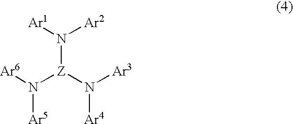
- said luminescent layer comprises a mixture of the bis-2,5-(2-benzazoyl) hydroquinone compound represented by the general formula (1) and an aromatic triamine compound represented by a general formula (4):
- Ar 1 -Ar 6 independently represents substituted or unsubstituted aromatic hydrocarbon group, or substituted or unsubstituted aromatic complex ring group, and “Z” represents trivalent substituted or substituted aromatic hydrocarbon group or substituted or unsubstituted aromatic complex ring group, any two of substituents possessed by Ar 1 -Ar 6 may form a ring.
- said luminescent layer comprises a mixture of the bis-2,5-(2-benzazoyl) hydroquinone compound represented by the general formula (1) and an oxime metal complex compound represented by general formula (5):
- each of R 9 -R 14 independently represents hydrogen atom, halogen atom, hydroxyl group, substituted or unsubstituted amino group, nitro group, cyano group, substituted or unsubstituted alkyl group, substituted or unsubstituted alkenyl group, substituted or unsubstituted cycloalkyl group, substituted or unsubstituted alkoxy group, substituted or unsubstituted aromatic hydrocarbon group, substituted or unsubstituted aromatic complex ring group, substituted or unsubstituted aralkyl group, substituted or unsubstituted aryloxy group, substituted or unsubstituted alkoxy carbonyl group, or carboxyl group, any two of substituents possessed by R 9 -R 14 may form a ring, and “L1” represents substituted or unsubstituted alkyl group, substituted or unsubstituted alkenyl group, substituted or unsubstitute
- said luminescent layer comprises a mixture of the bis-2,5-(2-benzazoyl) hydroquinone compound represented by the general formula (1) and an oxime metal complex compound represented by a general formula (6):
- each of R 15 -R 26 independently represents hydrogen atom, halogen atom, hydroxyl group, substituted or unsubstituted amino group, nitro group, cyano group, substituted or unsubstituted alkyl group, substituted or unsubstituted alkenyl group, substituted or unsubstituted cycloalkyl group, substituted or unsubstituted alkoxy group, substituted or unsubstituted aromatic hydrocarbon group, substituted or unsubstituted aromatic complex ring group, substituted or unsubstituted aralkyl group, substituted or unsubstituted aryloxy group, substituted or unsubstituted alkoxy carbonyl group, or carboxyl group, any two of substituents possessed by R 15 -R 26 may form a ring, and “L2” represents substituted or unsubstituted alkylene group, substituted or unsubstituted alkenylene group, substituted or unsubstitute
- cathode, said luminescent layer and said anode are sequentially provided, in descending order, over a predetermined substrate.
- cathode, an electron transfer layer, said luminescent layer, a hole transfer layer and said anode are sequentially provided, in descending order, over a predetermined substrate.
- cathode, an electron transfer layer, said luminescent layer and said anode are sequentially provided, in descending order, over a predetermined substrate.
- said cathode, said luminescent layer, a hole transfer layer and said anode are sequentially provided, in descending order, over a predetermined substrate.
- An organic electroluminescence device in accordance with the present invention has a cathode, an anode, and at least a single organic thin film including a luminescent layer between those cathode and anode, wherein at least one layer of said organic thin films contains a bis-2,5-(2-benzazoyl) hydroquinone compound represented by the general formula (1).
- the organic EL device in accordance with the present invention will hereinafter be described, but prior to this, processes for achieving the present invention will be described.
- the present inventors conducted extensive experiments and research to find the structure of a red-color organic EL device having superior high luminescent brightness and color purity as well as high stability in use. As a result, it could be found that a specified bis-2,5-(2-benzazoyl) hydroquinone compound is used for the organic EL device to obtain the red-color luminescent organic EL device which satisfies those requirements, whereby the present invention was achieved.
- each of R 1 -R 8 independently represents hydrogen atom, halogen atom, hydroxyl group, substituted or unsubstituted amino group, nitro group, cyano group, substituted or unsubstituted alkyl group, substituted or unsubstituted alkenyl group, substituted or unsubstituted cycloalkyl group, substituted or unsubstituted alkoxy group, substituted or unsubstituted aromatic hydrocarbon group, substituted or unsubstituted aromatic complex ring group, substituted or unsubstituted aralkyl group, substituted or unsubstituted aryloxy group, substituted or unsubstituted alkoxy carbonyl group, or carboxyl group, and any two of R 1 -R 8 may form a ring
- the aromatic amine compound, the aromatic diamine compound and the aromatic triamine compound compounds have structures represented by the general formulae (2), (3) and (4).
- each of Ar 1 -Ar 6 independently represents substituted or unsubstituted aromatic hydrocarbon group, or substituted or unsubstituted aromatic complex ring group.
- Y represents substituted or unsubstituted arylene group.
- Z represents trivalent substituted or unsubstituted aromatic hydrocarbon group or substituted or unsubstituted aromatic complex ring group.
- the oxime metal complex material used for the organic EL device in accordance with the present invention is a compound having a structure represented by the general formulae (5) and (6).
- each of R 9 -R 26 independently represents hydrogen atom, halogen atom, hydroxyl group, substituted or unsubstituted amino group, nitro group, cyano group, substituted or unsubstituted alkyl group, substituted or unsubstituted alkenyl group, substituted or unsubstituted cycloalkyl group, substituted or unsubstituted alkoxy group, substituted or unsubstituted aromatic hydrocarbon group, substituted or unsubstituted aromatic complex ring group, substituted or unsubstituted aralkyl group, substituted or unsubstituted aryloxy group, substituted or unsubstituted alkoxy carbonyl group, or carboxyl group.
- L1 represents substituted or unsubstituted alkyl group, substituted or unsubstituted alkenyl group, substituted or unsubstituted cycloalkyl group, substituted or unsubstituted aromatic hydrocarbon group, substituted or unsubstituted aromatic complex ring group, or substituted or unsubstituted aralkyl group.
- L2 represents substituted or unsubstituted alkylene group, substituted or unsubstituted alkenylene group, substituted or unsubstituted cycloalkylene group, substituted or unsubstituted arylene group, or substituted or unsubstituted aralkylene group.
- n is the integer in the range of 1-3.
- m is the integer in the range of 0-2.
- “1” is the integer of 0 or 1.
- s is the integer of 1 or 2.
- M represents a metal ion of (n+m)-valence or (s+1)-
- halogen atoms are fluorine, chlorine, and iodine.
- Substituted or unsubstituted amino group represents —NX1 X2.
- X1 and X2 there are available hydrogen atom, methyl groups, ethyl groups, propyl groups, isopropyl groups, n-butyl groups, s-butyl groups, isobutyl groups, t-butyl groups, n-pentyl groups, n-hexyl groups, n-heptyl groups, n-octyl groups, hydroxymethyl groups, 1-hydroxyethyl groups, 2-hydroxyethyl groups, 2-hydroxyisobutyl groups, 1,2-dihydroxyethyl groups, 1,3-dihydroxyisopropyl groups, 2,3-dihydroxy-t-butyl groups, 1,2,3-trihydroxypropyl groups, chloromethyl groups, 1-chloroethyl groups, 2-chloroethyl
- Available substituted or unsubstituted alkyl groups are methyl groups, ethyl groups, propyl groups, isopropyl groups, n-butyl groups, s-butyl groups, isobutyl groups, t-butyl groups, n-pentyl groups, n-hexyl groups, n-heptyl groups, n-octyl groups, hydroxymethyl groups, 1-hydroxyethyl groups, 2-hydroxyethyl groups, 2-hydroxyisobutyl groups, 1,2-dihydroxyethyl groups, 1,3-dihydroxyisopropyl groups, 2,3-dihydroxy-t-butyl groups, 1,2,3-trihydroxypropyl groups, chloromethyl groups, 1-chloroethyl groups, 2-chloroethyl groups, 2-chloroisobutyl groups, 1,2-dichloroethyl groups, 1,3-dichloroisopropyl groups, 2,3-dichloro
- Available substituted or unsubstituted alkenyl groups are vinyl groups, allyl groups, 2-butenyl groups, 3-butenyl groups, 1,3-butanedienyl groups, 1-methylvinyl groups, styryl groups, 2,2-diphenylvinyl groups, 1,2-diphenylvinyl groups, 1-methylallyl groups, 1,1-dimethylallyl groups, 2-methylallyl groups, 1-phenylallyl groups, 2-phenylallyl groups, 3-phenylallyl groups, 3,3-diphenylallyl groups, 1,2-dimethylallyl groups, 1-phenyl-1-butenyl groups, 3-phenyl-1-butenyl groups and the like.
- cycloalkyl groups are cyclopropyl groups, cyclobutyl groups, cyclopentyl groups, cyclohexyl groups, 4-methylcyclohexyl groups, and the like.
- Y1 Available substituted or unsubstituted alkoxy groups are groups represented by —OY1 and “Y1 ” may be methyl groups, ethyl groups, propyl groups, isopropyl groups, n-butyl groups, s-butyl groups, isobutyl groups, t-butyl groups, n-pentyl groups, n-hexyl groups, n-heptyl groups, n-octyl groups, hydroxymethyl groups, 1-hydroxyethyl groups, 2-hydroxyethyl groups, 2-hydroxyisobutyl groups, 1,2-dihydroxyethyl groups, 1,3-dihydroxyisopropyl groups, 2,3-dihydroxy-t-butyl groups, 1,2,3-trihydroxypropyl groups, chloromethyl groups, 1-chloroethyl groups, 2-chloroethyl groups, 2-chloroisobutyl groups, 1,2-dichloroethyl groups, 1,3
- phenyl groups available substituted or unsubstituted aromatic hydrocarbon groups are phenyl groups, 1-naphthyl groups, 2-naphthyl groups, 1-anthryl groups, 2-anthryl groups, 9-anthryl groups, 1-phenanthryl groups, 2-phenanthryl groups, 3-phenanthryl groups, 4-phenanthryl groups, 9-phenanthryl groups, 1-naphthacenyl groups, 2-naphthacenyl groups, 9-naphthacenyl groups, 1-pyrenyl groups, 2-pyrenyl groups, 4-pyrenyl groups, 2-biphenylyl groups, 3-biphenylyl groups, 4-biphenylyl groups, p-terphenyl-4-yl groups, p-terphenyl-3-yl groups, p-terphenyl-2-yl groups, m-terphenyl-4-yl groups, m-terphenyl-3-yl groups, m-
- Available substituted or unsubstituted aromatic hydrocarbon groups are 1-pyroryl groups, 2-pyroryl groups, 3-pyroryl groups, pyradinyl groups, 2-pyridinyl groups, 3-pyridinyl groups, 4-pyridinyl groups, 1-indolyl groups, 2-indolyl groups, 3-indolyl groups, 4-indolyl groups, 5-indolyl groups, 6-indolyl groups, 7-indolyl groups, 1-isoindolyl groups, 2-isoindolyl groups, 3-isoindolyl groups, 4-isoindolyl groups, 5-isoindolyl groups, 6-isoindolyl groups, 7-isoindolyl groups, 2-furyl groups, 3-furyl groups, 2-benzoflanyl groups, 3-benzoflanyl groups, 4-benzoflanyl groups, 5-benzoflanyl groups, 6-benzoflanyl groups, 7-benzoflanyl groups,
- Available substituted or unsubstituted aralkyl groups are benzyl groups, 1-phenylethyl groups, 2-phenylethyl groups, 1-phenylisopropyl groups, 2-phenylisopropyl groups, phenyl-t-butyl groups, ⁇ -naphthylmethyl groups, 1- ⁇ -naphthylethyl groups, 2- ⁇ -naphthylethyl groups, 1- ⁇ -naphthylisopropyl groups, 2- ⁇ -naphthylisopropyl groups, ⁇ -naphthylmethyl groups, 1- ⁇ -naphthylethyl groups, 2- ⁇ -naphthylethyl groups, 1- ⁇ -naphthylisopropyl groups, 2- ⁇ -naphthyl isopropyl groups, 1-pyrrolylmethyl groups, 2-(1-pyrrolyl)ethyl groups, p
- Z1 Available substituted or unsubstituted aryloxy groups are represented by —OZ1 and “Z1” may be phenyl groups, 1-naphthyl groups, 2-naphthyl groups, 1-anthryl groups, 2-anthryl groups, 9-anthryl groups, 1-phenanthryl groups, 2-phenanthryl groups, 3-phenanthryl groups, 4-phenanthryl groups, 9-phenanthryl groups, 1-naphthacenyl groups, 2-naphthacenyl groups, 9-naphthacenyl groups, 1-pyrenyl groups, 2-pyrenyl groups, 4-pyrenyl groups, 2-biphenylyl groups, 3-biphenylyl groups, 4-biphenylyl groups, p-terphenyl-4-yl groups, p-terphenyl-3-yl groups, p-terphenyl-2-yl groups, m-terphenyl-4-yl groups, m-ter
- Y2 Available substituted or unsubstituted alkoxycarbonyl groups are represented by —COOY2 and “Y2” may be methyl groups, ethyl groups, propyl groups, isopropyl groups, n-butyl groups, s-butyl groups, isobutyl groups, t-butyl groups, n-pentyl groups, n-hexyl groups, n-heptyl groups, n-octyl groups, hydroxymethyl groups, 1-hydroxyethyl groups, 2-hydroxyethyl groups, 2-hydroxyisobutyl groups, 1,2-dihydroxyethyl groups, 1,3-dihydroxyisopropyl groups, 2,3-dihydroxy-t-butyl groups, 1,2,3-trihydroxypropyl groups, chloromethyl groups, 1-chloroethyl groups, 2-chloroethyl groups, 2-chloroisobutyl groups, 1,2-dichloroethyl groups,
- Available substituted or unsubstituted arylene groups are aromatic hydrocarbon or condensed polycyclic hydrocarbon such as substituted or unsubstituted benzene, naphthalene, anthracene, phenanthrene, naphthalene, pyrene, biphenyl, terphenyl, as well as divalent groups of complex ring compounds or condensed complex ring compounds from which two hydrogen atoms have been eliminated, such as substituted or unsubstituted carbazole, pyrrole, thiophene, furan, imidazole, pyrazole isothiazole, pyridine, pyrazine, pyrimidine, pyridazine, frazane, thianthrene, isobenzofuran, phenoxazine, indolizine, indole, isoindole, 1H-indazole, purine, quinoline, isoquinoline, phthalazine, naphth
- Available substituted or unsubstituted aromatic hydrocarbon groups of trivalent are substituted or unsubstituted benzene, naphthalene, anthracene, phenanthrene, naphthalene, pyrene, biphenyl, terphenyl.
- Trivalent groups of complex ring compounds or condensed complex ring compounds from which three hydrogen atoms are eliminated such as substituted or unsubstituted carbazole, pyrrole, thiophene, furan, imidazole, pyrazole, isothiazole, pyridine, pyrazine, pyrimidine, pyridazine, frazane, thianthrene, isobenzofuran, phenoxazine, indolizine, indole, isoindole, 1H-indazole, purine, quinoline, isoquinoline, phthalazine, naphthyridine, quinoxaline, quinazoline, cinnoline, pteridine, carbazole, ⁇ -carbazoline, phenanthridine, acridine, perimidine, phenanthroline, phenazine, pheno
- Available substituted or unsubstituted alkylene groups are divalent groups of alkane, from which two hydrogen atoms have been eliminated, such as substituted or unsubstituted methane, ethane, propane, n-butane, 2-methylpropane, n-pentane, 2-methylbutane, 2,2-dimethylpropane, n-hexane, 2-methyl-n-pentane, 3-methyl-n-pentane, 2,2-dimethylbutane, 2,3-dimethylbutane.
- Available substituted or unsubstituted alkenylene groups are divalent groups of alkene, from which two hydrogen atoms have been eliminated, such as substituted or unsubstituted ethylene, propylene, 1-butene, 2-butene, 1,3-butadiene.
- Available substituted or unsubstituted cycloalkylene groups are divalent groups of cycloalkane, from which two hydrogen atoms have been eliminated, such as substituted or unsubstituted cyclopropane, cyclobutane, cyclopentane, cyclohexane.
- Substituents of those polyhydric groups may be halogen atoms, hydroxyl group, substituted or unsubstituted amino group, nitro group, cyano group, substituted or unsubstituted alkyl group, substituted or unsubstituted alkenyl group, substituted or unsubstituted cycloalkyl group, substituted or unsubstituted alkoxy group, substituted or unsubstituted aromatic hydrocarbon group, substituted or unsubstituted aromatic complex ring group, substituted or unsubstituted aralkyl group, substituted or unsubstituted aryloxy group, substituted or unsubstituted alkoxy carbonyl group, or carboxyl group.
- divalent groups forming a ring examples include tetramethylene groups, pentamethylene groups, hexamethylene groups, diphenylmethane-2,2′-diyl groups, diphenylethane-3,3′-diyl groups, diphenylpropane-4,4′-diyl groups, 1,3-butadienyl-1,4-en groups.
- metals forming oxime metal complex there are available aluminum, beryllium, bismuth, cadmium, curium, cobalt, copper, iron, gallium, germanium, mercury, indium, lanthanum, magnesium, molybdenum, niobium, antimony, scandium, tin, tantalum, thulium, titanium, uranium, tungsten, zirconium, vanadium, zinc and the like.
- FIG. 1 is a cross sectional view illustrative of an organic EL device in accordance with example 1 of the present invention.
- FIG. 2 is a cross sectional view illustrative of an organic EL device in accordance with example 11 of the present invention.
- FIG. 3 is a cross sectional view illustrative of an organic EL device in accordance with example 30 of the present invention.
- FIG. 4 is a cross sectional view illustrative of an organic EL device in accordance with example 35 of the present invention.
- the organic EL device in accordance with the present invention has a structure of laminations of one or two or more organic thin films between a cathode and an anode.
- the following four examples may be considered.
- the compounds represented by the general formula (1) are mixed with luminescent materials represented by the general formulae (2) through (6) to be used for the luminescent layer of the above organic EL device. It is possible to mix, in addition to the compounds represented by the general formula (1), other materials of hole transport material, luminescent materials and electron transport materials.
- the hole transport materials to be used in the organic EL device in accordance with the present invention should not be limited. Any compounds normally used as the hole transport materials may be available.
- compounds 45-50 such as bis(di(p-tolyl)aminophenyl)-1,1-cyclohexane (compound 45), N,N′-diphenyl-N,N′-bis(3-methylphenyl)-1,1′-biphenyl-4,4′-diamine (compound 46), N,N′-diphenyl-N-N′-bis(1-naphthyl)-(1,1′-biphenyl)-4,4′-diamine (compound 47), and the like as well as compounds (17) through (30) such as diamine, triamine, tetraamine and starburst type molecules (compounds 48-50).
- the electron transport materials to be used in the organic EL device in accordance with the present invention should not be limited. Any compounds normally used as the electron transport materials may be available.
- compounds 51-54 such as oxadiazole derivatives such as 2-(4-biphenyl)-5-(4-t-butylphenyl)-1,3,4-oxadiazole (compound 51), bis ⁇ 2-(4-t-butylphenyl)-1,3,4-oxadiazole ⁇ -m-phenylene (compound 52), as well as triazole derivatives (compounds 53, 54).
- Oxime metal complex of compounds (31) through (44) may also be available as the electron transport material.
- the anode of the organic thin film EL device may serve to inject holes into the hole transport layer and it is effective that the anode has a work function of not less than 4.5 eV.
- Available anode materials for the organic EL device in accordance with the present invention are, for example, indium tin oxide alloy (ITO), tin oxide (NESA), gold, silver, platinum, and copper.
- the cathode serves to inject electrons into the electron transport layer, for which reason it is preferable that the cathode material is smaller in work function than the anode material.
- the cathode material should not be limited but, there are, for example, available indium, aluminum, magnesium, magnesium-indium alloy, magnesium-aluminum alloy, aluminum-lithium alloy, aluminum-scandium-lithium alloy, magnesium-silver alloy and the like.
- Methods for forming individual layers of the organic EL device in accordance with the present invention should not be limited.
- Known techniques are available such as a vacuum evaporation method, and a spin coating method.
- the organic thin film layer containing a mixture of the compound represented by the above general formula (1) with a luminescent material represented by the general formulae (2) through (6) may be formed by known methods such as a vacuum evaporation method, a molecular beam epitaxy method, a dipping method with use of a solution dissolved into a solvent, application methods such as a spin coating method, a scanting method, a barcode method, and a roll coating method.
- Thicknesses of the individual layers of the organic EL device in accordance with the present invention should not be limited. If, however, the thickness is too thin, then defects such as pin holes are likely to be formed. If the thickness is too thick, then a high voltage application is required and the efficiency decreases. For those reasons, the thicknesses of the individual layers are preferably in the range of one or a few nanometers through one micrometer.
- FIG. 1 A cross sectioned structure of an organic EL device in accordance with the present invention is shown in FIG. 1 .
- the organic EL device in accordance with the present invention comprises a glass substrate 1 , an anode 2 and a cathode 6 formed over the glass substrate 1 , and a luminescent layer 4 sandwiched between the anode 2 and the cathode 6 .
- a magnesium-silver alloy was vacuum-evaporated to form a film of 200 nanometers in thickness, thereby forming an organic EL device.
- a direct current voltage of 5V was applied across the anode 2 and the cathode 6 of this organic EL device.
- a red-color luminescence of 40 cd/m 2 was obtained.
- the organic EL device was fabricated by the same processes as in the embodiment 1 except that as the luminescent layer 4 , a compound (10) and a compound (24) were co-evaporated at a weight ratio of 1:10 to form a thin film of 50 nanometers in thickness. A direct current voltage of 5V was applied across the anode 2 and the cathode 6 of this organic EL device. A red-color luminescence of 60 cd/m 2 was obtained.
- the organic EL device was fabricated by the same processes as in the embodiment 1 except that as the luminescent layer 4 , a compound (13) and a compound (26) were co-evaporated at a weight ratio of 1:10 to form a thin film of 50 nanometers in thickness. A direct current voltage of 5V was applied across the anode 2 and the cathode 6 of this organic EL device. A red-color luminescence of 50 cd/m 2 was obtained.
- the organic EL device was fabricated by the same processes as in the embodiment 1 except that as the luminescent layer 4 , a compound (13) and a compound (24) were co-evaporated at a weight ratio of 1:10 to form a thin film of 50 nanometers in thickness. A direct current voltage of 5V was applied across the anode 2 and the cathode 6 of this organic EL device. A red-color luminescence of 40 cd/m 2 was obtained.
- the organic EL device was fabricated by the same processes as in the embodiment 1 except that as the luminescent layer 4 , a compound (13) and a compound (28) were co-evaporated at a weight ratio of 1:10 to form a thin film of 50 nanometers in thickness. A direct current voltage of 5V was applied across the anode 2 and the cathode 6 of this organic EL device. A red-color luminescence of 60 cd/m 2 was obtained.
- the organic EL device was fabricated by the same processes as in the embodiment 1 except that as the luminescent layer 4 , a compound (13) and a compound (31) were co-evaporated at a weight ratio of 1:10 to form a thin film of 50 nanometers in thickness. A direct current voltage of 5V was applied across the anode 2 and the cathode 6 of this organic EL device. A red-color luminescence of 60 cd/m 2 was obtained.
- the organic EL device was fabricated by the same processes as in the embodiment 1 except that as the luminescent layer 4 , a compound (13) and a compound (33) were co-evaporated at a weight ratio of 1:10 to form a thin film of 50 nanometers in thickness. A direct current voltage of 5V was applied across the anode 2 and the cathode 6 of this organic EL device. A red-color luminescence of 40 cd/m 2 was obtained.
- the organic EL device was fabricated by the same processes as in the embodiment 1 except that as the luminescent layer 4 , a compound (13) and a compound (40) were co-evaporated at a weight ratio of 1:10 to form a thin film of 50 nanometers in thickness. A direct current voltage of 5V was applied across the anode 2 and the cathode 6 of this organic EL device. A red-color luminescence of 60 cd/m 2 was obtained.
- a cross sectioned structure of an organic EL device in accordance with the example 9 is the same as the cross sectioned structure of the organic EL device in the example 1 shown in FIG. 1 . Fabrication processes for the organic EL device in accordance with example 9 will be described below.
- An ITO was formed on a glass substrate 1 by a sputtering method so that a sheet resistance becomes 20 ⁇ / ⁇ , thereby forming an anode.
- a chloroform solution including a mixture a compound (7) with a compound (17) at a weight ratio of 1:10 was used to carry out a spin coating method to form a luminescent layer 4 of 40 nanometers in thickness.
- a magnesium-silver alloy was vacuum-evaporated to form a film of 200 nanometers in thickness, thereby forming an organic EL device.
- a direct current voltage of 5V was applied across the anode 2 and the cathode 6 of this organic EL device.
- a red-color luminescence of 40 cd/m 2 was obtained.
- the organic EL device was fabricated by the same processes as in the embodiment 9 except that a chloroform solution including a mixture of a compound (8) with a compound (25) at a weight ratio of 1:10 was used to carry out a spin coating method to form a luminescent layer 4 of 40 nanometers in thickness. A direct current voltage of 5V was applied across the anode 2 and the cathode 6 of this organic EL device. A red-color luminescence of 50 cd/m 2 was obtained.
- FIG. 2 A cross sectioned structure of an organic EL device in accordance with example 11 is shown in FIG. 2 .
- the organic EL device in accordance with this example comprises a glass substrate 1 , an anode 2 and a cathode 6 formed over the glass substrate 1 , and a hole transport layer 3 , a luminescent layer 4 and an electron transport layer 5 sandwiched between the anode 2 and the cathode 6 .
- An ITO was formed on a glass substrate 1 by a sputtering method so that a sheet resistance becomes 20 ⁇ / ⁇ , thereby forming an anode 2 .
- a hole transport layer 3 N,N′-diphenyl-N,N′-bis(3-methylphenyl)-1,1′-biphenyl-4,4′-diamine (compound 46) was formed by a vacuum evaporation to form a layer of 50 nanometers in thickness.
- a compound (9) and a compound (18) were co-evaporated at a weight ratio of 1:10 to form a thin film of 40 nanometers in thickness.
- 2-(4-biphenyl)-5-(4-t-butylphenyl)-1,3,4-oxadiazole compound 51
- compound 51 2-(4-biphenyl)-5-(4-t-butylphenyl)-1,3,4-oxadiazole
- a cathode 6 a magnesium-silver alloy was vacuum-evaporated to form a film of 200 nanometers in thickness, thereby forming an organic EL device.
- a direct current voltage of 10V was applied across the anode 2 and the cathode 6 of this organic EL device.
- a red-color luminescence of 400 cd/m 2 was obtained.
- the organic EL device was fabricated by the same processes as in the embodiment 11 except that a compound (11) and a compound (19) were co-evaporated at a weight ratio of 1:10. A direct current voltage of 10V was applied across the anode 2 and the cathode 6 of this organic EL device. A red-color luminescence of 500 cd/m 2 was obtained.
- the organic EL device was fabricated by the same processes as in the embodiment 11 except that a compound (12) and a compound (22) were co-evaporated at a weight ratio of 1:10. A direct current voltage of 10V was applied across the anode 2 and the cathode 6 of this organic EL device. A red-color luminescence of 500 cd/m 2 was obtained.
- the organic EL device was fabricated by the same processes as in the embodiment 11 except that a compound (14) and a compound (24) were co-evaporated at a weight ratio of 1:10. A direct current voltage of 10V was applied across the anode 2 and the cathode 6 of this organic EL device. A red-color luminescence of 400 cd/m 2 was obtained.
- the organic EL device was fabricated by the same processes as in the embodiment 11 except that a compound (15) and a compound (26) were co-evaporated at a weight ratio of 1:10. A direct current voltage of 10V was applied across the anode 2 and the cathode 6 of this organic EL device. A red-color luminescence of 550 cd/m 2 was obtained.
- the organic EL device was fabricated by the same processes as in the embodiment 11 except that a compound (16) and a compound (27) were co-evaporated at a weight ratio of 1:10. A direct current voltage of 10V was applied across the anode 2 and the cathode 6 of this organic EL device. A red-color luminescence of 560 cd/m 2 was obtained.
- the organic EL device was fabricated by the same processes as in the embodiment 11 except that a compound (10) and a compound (28) were co-evaporated at a weight ratio of 1:10. A direct current voltage of 10V was applied across the anode 2 and the cathode 6 of this organic EL device. A red-color luminescence of 580 cd/m 2 was obtained.
- the organic EL device was fabricated by the same processes as in the embodiment 11 except that a compound (13) and a compound (24) were co-evaporated at a weight ratio of 1:10. A direct current voltage of 10V was applied across the anode 2 and the cathode 6 of this organic EL device. A red-color luminescence of 800 cd/m 2 was obtained.
- the organic EL device was fabricated by the same processes as in the embodiment 11 except that a compound (13) and a compound (26) were co-evaporated at a weight ratio of 1:10. A direct current voltage of 10V was applied across the anode 2 and the cathode 6 of this organic EL device. A red-color luminescence of 960 cd/m 2 was obtained.
- the organic EL device was fabricated by the same processes as in the embodiment 11 except that a compound (13) and a compound (28) were co-evaporated at a weight ratio of 1:10. A direct current voltage of 10V was applied across the anode 2 and the cathode 6 of this organic EL device. A red-color luminescence of 800 cd/m 2 was obtained.
- the organic EL device was fabricated by the same processes as in the embodiment 11 except that a compound (13) and a compound (29) were co-evaporated at a weight ratio of 1:10. A direct current voltage of 10V was applied across the anode 2 and the cathode 6 of this organic EL device. A red-color luminescence of 900 cd/m 2 was obtained.
- the organic EL device was fabricated by the same processes as in the embodiment 11 except that a compound (13) and a compound (33) were co-evaporated at a weight ratio of 1:10. A direct current voltage of 10V was applied across the anode 2 and the cathode 6 of this organic EL device. A red-color luminescence of 1000 cd/m 2 was obtained.
- the organic EL device was fabricated by the same processes as in the embodiment 11 except that a compound (13) and a compound (35) were co-evaporated at a weight ratio of 1:10. A direct current voltage of 10V was applied across the anode 2 and the cathode 6 of this organic EL device. A red-color luminescence of 950 cd/m 2 was obtained.
- the organic EL device was fabricated by the same processes as in the embodiment 11 except that a compound (13) and a compound (37) were co-evaporated at a weight ratio of 1:10. A direct current voltage of 10V was applied across the anode 2 and the cathode 6 of this organic EL device. A red-color luminescence of 1200 cd/m 2 was obtained.
- the organic EL device was fabricated by the same processes as in the embodiment 11 except that a compound (13) and a compound (40) were co-evaporated at a weight ratio of 1:10. A direct current voltage of 10V was applied across the anode 2 and the cathode 6 of this organic EL device. A red-color luminescence of 1000 cd/m 2 was obtained.
- the organic EL device was fabricated by the same processes as in the embodiment 11 except that a compound (13) and a compound (43) were co-evaporated at a weight ratio of 1:10. A direct current voltage of 10V was applied across the anode 2 and the cathode 6 of this organic EL device. A red-color luminescence of 1200 cd/m 2 was obtained.
- the organic EL device was fabricated by the same processes as in the embodiment 19 except that as the hole transport layer 3 , N,N′-diphenyl-N-N′-bis(1-naphthyl)-(1,1′-biphenyl)-4,4′-diamine (compound 47) was used and as the electron transport layer 5 , bis ⁇ 2-(4-t-butylphenyl)-1,3,4-oxadiazole ⁇ -m-phenylene (compound 52) was used. A direct current voltage of 10V was applied across the anode 2 and the cathode 6 of this organic EL device. A red-color luminescence of 1000 cd/m 2 was obtained.
- the organic EL device was fabricated by the same processes as in the embodiment 19 except that as the hole transport layer 3 , starburst type molecule (compound 48) was used and as the electron transport layer 5 , triazole derivative (compound 53) was used. A direct current voltage of 10V was applied across the anode 2 and the cathode 6 of this organic EL device. A red-color luminescence of 1300 cd/m 2 was obtained.
- the organic EL device was fabricated by the same processes as in the embodiment 19 except that as the hole transport layer 3 , starburst type molecule (compound 49) was used and as the electron transport layer 5 , triazole derivative (compound 54) was used. A direct current voltage of 10V was applied across the anode 2 and the cathode 6 of this organic EL device. A red-color luminescence of 1400 cd/m 2 was obtained.
- FIG. 3 A cross sectioned structure of an organic EL device in accordance with example 30 is shown in FIG. 3 .
- the organic EL device in accordance with this example comprises a glass substrate 1 , an anode 2 and a cathode 6 formed over the glass substrate 1 , and a luminescent layer 4 and an electron transport layer 5 sandwiched between the anode 2 and the cathode 6 .
- An ITO was formed on a glass substrate 1 by a sputtering method so that a sheet resistance becomes 20 ⁇ / ⁇ , thereby forming an anode 2 .
- a luminescent layer 4 N,N′-diphenyl-N-N′-bis(1-naphthyl)-(1,1′-biphenyl)-4,4′-diamine (compound 47), a compound (9) and a compound (18) were co-evaporated at a weight ratio of 1:1:10 to form a thin film of 50 nanometers in thickness.
- triazole derivative compound 53
- a magnesium-silver alloy was vacuum-evaporated to form a film of 200 nanometers in thickness, thereby forming an organic EL device.
- a direct current voltage of 10V was applied across the anode 2 and the cathode 6 of this organic EL device.
- a red-color luminescence of 600 cd/m 2 was obtained.
- the organic EL device was fabricated by the same processes as in the embodiment 30 except that in place of the compound (26), a compound (30) was used. A direct current voltage of 10V was applied across the anode 2 and the cathode 6 of this organic EL device. A red-color luminescence of 750 cd/m 2 was obtained.
- the organic EL device was fabricated by the same processes as in the embodiment 30 except that a compound (13) and a compound (25) were co-evaporated at a weight ratio of 1:10 to form a thin film of 50 nanometers in thickness.
- a direct current voltage of 10V was applied across the anode 2 and the cathode 6 of this organic EL device.
- a red-color luminescence of 710 cd/m 2 was obtained.
- the organic EL device was fabricated by the same processes as in the embodiment 32 except that in place of the compound (25), a compound (29) was used. A direct current voltage of 10V was applied across the anode 2 and the cathode 6 of this organic EL device. A red-color luminescence of 780 cd/m 2 was obtained.
- a cross sectioned structure of an organic EL device in accordance with example 34 is the same as the cross sectioned structure of the organic EL device in accordance with example 30 shown in FIG. 3 . Fabrication processes for the organic EL device in accordance with example 34 will be described below.
- An ITO was formed on a glass substrate 1 by a sputtering method so that a sheet resistance becomes 20 ⁇ / ⁇ , thereby forming an anode 2.
- a chloroform solution containing N,N′-diphenyl-N-N′-bis(1-naphthyl)-(1,1′-biphenyl)-4,4′-diamine (compound 47), a compound (10) and a compound (25) at a weight ratio of 1:1:10 was used to carry out a spin coating method thereby to form a luminescent layer 4 of 40 nanometers in thickness.
- a triazole derivative (compound 54) was vacuum-evaporated to form an electron transport layer 5 of 50 nanometers in thickness.
- a magnesium-silver alloy was vacuum-evaporated to form a film of 200 nanometers in thickness, thereby forming an organic EL device.
- a direct current voltage of 10V was applied across the anode 2 and the cathode 6 of this organic EL device.
- a red-color luminescence of 580 cd/m 2 was obtained.
- FIG. 4 A cross sectioned structure of an organic EL device in accordance with example 35 is shown in FIG. 4 .
- the organic EL device in accordance with this example comprises a glass substrate 1 , an anode 2 and a cathode 6 formed over the glass substrate 1 , and a hole transport layer 3 and a luminescent layer 4 sandwiched between the anode 2 and the cathode 6 .
- An ITO was formed on a glass substrate 1 by a sputtering method so that a sheet resistance becomes 20 ⁇ / ⁇ , thereby forming an anode 2 .
- As a hole transport layer 3 N,N′-diphenyl-N-N′-bis(1-naphthyl)-(1,1′-biphenyl)-4,4′-diamine (compound 47) was vacuum-evaporated to form a layer of 50 nanometers in thickness.
- a compound (13) and a compound (31) were co-evaporated at a weight ratio of 1:10 to form a thin film of 50 nanometers in thickness.
- a magnesium-silver alloy was vacuum-evaporated to form a film of 200 nanometers in thickness, thereby forming an organic EL device.
- a direct current voltage of 10V was applied across the anode 2 and the cathode 6 of this organic EL device.
- a red-color luminescence of 790 cd/m 2 was obtained.
- the organic EL device was fabricated by the same processes as in the embodiment 35 except that in place of the compound (31), a compound (32) was used. A direct current voltage of 10V was applied across the anode 2 and the cathode 6 of this organic EL device. A red-color luminescence of 900 cd/m 2 was obtained.
- the organic EL device was fabricated by the same processes as in the embodiment 35 except that in place of the compound (31), a compound (39) was used. A direct current voltage of 10V was applied across the anode 2 and the cathode 6 of this organic EL device. A red-color luminescence of 910 cd/m 2 was obtained.
- the organic EL device was fabricated by the same processes as in the embodiment 35 except that in place of the compound (31), a compound (44) was used. A direct current voltage of 10V was applied across the anode 2 and the cathode 6 of this organic EL device. A red-color luminescence of 770 cd/m 2 was obtained.
- the organic EL device was fabricated by the same processes as in the embodiment 35 except that a compound (11), a compound (13), and a compound (37) were co-evaporated at a weight ratio of 2:1:10 to form a thin film of 50 nanometers in thickness.
- a direct current voltage of 10V was applied across the anode 2 and the cathode 6 of this organic EL device.
- a red-color luminescence of 840 cd/m 2 was obtained.
- At least one layer of the organic thin film layers contains a bis-2,5-(2-benzazoyl) hydroquinone compound represented by the general formula (1), so that as compared to the conventional organic EL device, the luminescent brightness and the color purity are higher and an operational stability is superior to obtain the red-color luminescence.
Abstract
Description


Claims (10)


Applications Claiming Priority (2)
| Application Number | Priority Date | Filing Date | Title |
|---|---|---|---|
| JP10-092224 | 1998-03-23 | ||
| JP10092224A JP3092584B2 (en) | 1998-03-23 | 1998-03-23 | Organic electroluminescence device |
Publications (1)
| Publication Number | Publication Date |
|---|---|
| US6630253B1 true US6630253B1 (en) | 2003-10-07 |
Family
ID=14048479
Family Applications (1)
| Application Number | Title | Priority Date | Filing Date |
|---|---|---|---|
| US09/274,963 Expired - Lifetime US6630253B1 (en) | 1998-03-23 | 1999-03-23 | Organic electroluminescence device |
Country Status (4)
| Country | Link |
|---|---|
| US (1) | US6630253B1 (en) |
| JP (1) | JP3092584B2 (en) |
| KR (1) | KR100315316B1 (en) |
| TW (1) | TW415157B (en) |
Cited By (6)
| Publication number | Priority date | Publication date | Assignee | Title |
|---|---|---|---|---|
| US20040151943A1 (en) * | 2003-02-04 | 2004-08-05 | Shuit-Tong Lee | Electroluminescent devices |
| US20040191565A1 (en) * | 2002-12-26 | 2004-09-30 | Optrex Corporation | Organic electroluminescence device |
| US20050129841A1 (en) * | 2000-07-12 | 2005-06-16 | 3M Innovative Properties Company | Encapsulated organic electronic devices and method for making same |
| US20070285008A1 (en) * | 2004-08-23 | 2007-12-13 | Shinji Matsuo | Organic Electroluminescent Element |
| US20090128011A1 (en) * | 2005-10-31 | 2009-05-21 | Nippon Steel Chemical Co., Ltd. | Organic Electroluminescent Device |
| US20090309491A1 (en) * | 2008-06-13 | 2009-12-17 | O-Hyun Kwon | Organic light emitting device comprising layer comprising organic-metal complex and method of preparing the same |
Families Citing this family (8)
| Publication number | Priority date | Publication date | Assignee | Title |
|---|---|---|---|---|
| US6821644B2 (en) | 1999-12-15 | 2004-11-23 | Samsung Sdi Co., Ltd. | Organic electroluminescent device |
| JP4558153B2 (en) * | 2000-07-27 | 2010-10-06 | 三星モバイルディスプレイ株式會社 | Organic electroluminescence device |
| JP3899907B2 (en) * | 2000-11-24 | 2007-03-28 | 東レ株式会社 | Light emitting element |
| JP3650082B2 (en) * | 2001-06-04 | 2005-05-18 | 三洋電機株式会社 | Organic electroluminescence device, light emitting material, and organic compound |
| JP4675513B2 (en) * | 2001-07-10 | 2011-04-27 | 新日鐵化学株式会社 | Aluminum chelate complex and organic electroluminescence device |
| KR100577179B1 (en) * | 2001-10-30 | 2006-05-10 | 엘지전자 주식회사 | Organic Electroluminescent Element |
| GB0426674D0 (en) * | 2004-12-06 | 2005-01-05 | Elam T Ltd | Electroluminescent materials and devices |
| KR100969602B1 (en) | 2008-02-01 | 2010-07-12 | 경희대학교 산학협력단 | Green organic light emitting material and organic light emitting device using the same |
Citations (7)
| Publication number | Priority date | Publication date | Assignee | Title |
|---|---|---|---|---|
| US3673202A (en) * | 1970-01-07 | 1972-06-27 | Gen Electric | 2,5-bis(2-benzazolyl)hydroquinones and their derivatives |
| US4769292A (en) * | 1987-03-02 | 1988-09-06 | Eastman Kodak Company | Electroluminescent device with modified thin film luminescent zone |
| JPH03790A (en) * | 1989-02-08 | 1991-01-07 | Ricoh Co Ltd | Electroluminescent element |
| US5085947A (en) * | 1989-03-23 | 1992-02-04 | Ricoh Company, Ltd. | Electroluminescence device |
| US5085946A (en) * | 1989-01-13 | 1992-02-04 | Ricoh Company, Ltd. | Electroluminescence device |
| US5281489A (en) * | 1990-03-16 | 1994-01-25 | Asashi Kasei Kogyo Kabushiki Kaisha | Electroluminescent element |
| US5409783A (en) * | 1994-02-24 | 1995-04-25 | Eastman Kodak Company | Red-emitting organic electroluminescent device |
-
1998
- 1998-03-23 JP JP10092224A patent/JP3092584B2/en not_active Expired - Fee Related
-
1999
- 1999-03-22 TW TW088104485A patent/TW415157B/en not_active IP Right Cessation
- 1999-03-23 US US09/274,963 patent/US6630253B1/en not_active Expired - Lifetime
- 1999-03-23 KR KR1019990009763A patent/KR100315316B1/en not_active IP Right Cessation
Patent Citations (7)
| Publication number | Priority date | Publication date | Assignee | Title |
|---|---|---|---|---|
| US3673202A (en) * | 1970-01-07 | 1972-06-27 | Gen Electric | 2,5-bis(2-benzazolyl)hydroquinones and their derivatives |
| US4769292A (en) * | 1987-03-02 | 1988-09-06 | Eastman Kodak Company | Electroluminescent device with modified thin film luminescent zone |
| US5085946A (en) * | 1989-01-13 | 1992-02-04 | Ricoh Company, Ltd. | Electroluminescence device |
| JPH03790A (en) * | 1989-02-08 | 1991-01-07 | Ricoh Co Ltd | Electroluminescent element |
| US5085947A (en) * | 1989-03-23 | 1992-02-04 | Ricoh Company, Ltd. | Electroluminescence device |
| US5281489A (en) * | 1990-03-16 | 1994-01-25 | Asashi Kasei Kogyo Kabushiki Kaisha | Electroluminescent element |
| US5409783A (en) * | 1994-02-24 | 1995-04-25 | Eastman Kodak Company | Red-emitting organic electroluminescent device |
Non-Patent Citations (4)
| Title |
|---|
| Derwent-Acc-No.: 1986-091302 (for JP 61-37886-A, Feb. 1986).* * |
| Derwent-Acc-No.: 1990-345251 (for JP 2-250292-A, Oct. 1990; and for US 5,085,947, Feb. 1992).* * |
| Derwent-Acc-No.: 1991-018972 (for JP 2-291696-A, Dec. 1990; and for US 5,085,946, Feb. 1992).* * |
| Derwent-Acc-No.: 1991-048183 (for JP 3-790-A, Jan. 1991). * |
Cited By (12)
| Publication number | Priority date | Publication date | Assignee | Title |
|---|---|---|---|---|
| US20050129841A1 (en) * | 2000-07-12 | 2005-06-16 | 3M Innovative Properties Company | Encapsulated organic electronic devices and method for making same |
| US20110177637A1 (en) * | 2000-07-12 | 2011-07-21 | 3M Innovative Properties Company | Encapsulated organic electronic devices and method for making same |
| US8657985B2 (en) | 2000-07-12 | 2014-02-25 | 3M Innovative Properties Company | Encapsulated organic electronic devices and method for making same |
| US20040191565A1 (en) * | 2002-12-26 | 2004-09-30 | Optrex Corporation | Organic electroluminescence device |
| US6927537B2 (en) * | 2002-12-26 | 2005-08-09 | Optrex Corporation | Organic electroluminescence device |
| US20040151943A1 (en) * | 2003-02-04 | 2004-08-05 | Shuit-Tong Lee | Electroluminescent devices |
| US7232617B2 (en) * | 2003-02-04 | 2007-06-19 | Cityu Research Limited | Electroluminescent devices |
| US20070285008A1 (en) * | 2004-08-23 | 2007-12-13 | Shinji Matsuo | Organic Electroluminescent Element |
| US20090128011A1 (en) * | 2005-10-31 | 2009-05-21 | Nippon Steel Chemical Co., Ltd. | Organic Electroluminescent Device |
| US8119257B2 (en) * | 2005-10-31 | 2012-02-21 | Nippon Steel Chemical Co., Ltd. | Organic electroluminescent device |
| US20090309491A1 (en) * | 2008-06-13 | 2009-12-17 | O-Hyun Kwon | Organic light emitting device comprising layer comprising organic-metal complex and method of preparing the same |
| US8703301B2 (en) * | 2008-06-13 | 2014-04-22 | Samsung Display Co., Ltd. | Organic light emitting device comprising layer comprising organic-metal complex and method of preparing the same |
Also Published As
| Publication number | Publication date |
|---|---|
| JP3092584B2 (en) | 2000-09-25 |
| TW415157B (en) | 2000-12-11 |
| KR100315316B1 (en) | 2001-11-28 |
| JPH11273866A (en) | 1999-10-08 |
| KR19990078128A (en) | 1999-10-25 |
Similar Documents
| Publication | Publication Date | Title |
|---|---|---|
| EP1718121B1 (en) | Organic electroluminescent device | |
| US20060061265A1 (en) | Aromatic amine derivative and organic electroluminescent element employing the same | |
| EP2085371A1 (en) | Fluoranthene compound, organic electroluminescent device using the fluoranthene compound, and organic electroluminescent material-containing solution | |
| US6492041B2 (en) | Organic electroluminescent device having high efficient luminance | |
| US6759144B2 (en) | Organic electroluminescence device | |
| US6784452B2 (en) | Organic thin film transistor | |
| US20020022151A1 (en) | Organic electroluminescent device | |
| US6630253B1 (en) | Organic electroluminescence device | |
| US6468675B1 (en) | Organic electroluminescent device having high luminance efficiency | |
| US20070196688A1 (en) | Organic electroluminescence device | |
| US6465116B1 (en) | Organic electroluminescent device | |
| EP2073289B1 (en) | Organic electroluminescent device | |
| US20080226940A1 (en) | Dibenzo[c,g]triphenylene derivative and organic electroluminescence device using the same | |
| EP0996177A2 (en) | Organic electroluminescent device using hole-injectable, light-emitting material | |
| KR100360692B1 (en) | Organic electroluminescent device | |
| JP3011165B2 (en) | Organic electroluminescent device | |
| KR100387166B1 (en) | Organic Electroluminescence Device | |
| US6921588B2 (en) | Organic electroluminescent device having high luminance efficiency | |
| US6821644B2 (en) | Organic electroluminescent device | |
| KR100364951B1 (en) | Organic Electroluminescence Material and Electroluminescence Device Using the Same | |
| US6699594B1 (en) | Organic electroluminescent device | |
| US20020079489A1 (en) | Organic electroluminescent device | |
| JP3581309B2 (en) | Organic electroluminescence device |
Legal Events
| Date | Code | Title | Description |
|---|---|---|---|
| AS | Assignment |
Owner name: NEC CORPORATION, JAPAN Free format text: ASSIGNMENT OF ASSIGNORS INTEREST;ASSIGNORS:TANAKA, TAIZOU;TOGUCHI, SATORU;MORI, KENJI;REEL/FRAME:009860/0614;SIGNING DATES FROM 19980318 TO 19990318 |
|
| STCF | Information on status: patent grant |
Free format text: PATENTED CASE |
|
| FEPP | Fee payment procedure |
Free format text: PAYOR NUMBER ASSIGNED (ORIGINAL EVENT CODE: ASPN); ENTITY STATUS OF PATENT OWNER: LARGE ENTITY |
|
| AS | Assignment |
Owner name: SAMSUNG SDI CO., LTD., KOREA, REPUBLIC OF Free format text: ASSIGNMENT OF ASSIGNORS INTEREST;ASSIGNOR:NEC CORPORATION;REEL/FRAME:015147/0586 Effective date: 20040315 |
|
| FPAY | Fee payment |
Year of fee payment: 4 |
|
| AS | Assignment |
Owner name: SAMSUNG MOBILE DISPLAY CO., LTD., KOREA, REPUBLIC Free format text: ASSIGNMENT OF ASSIGNORS INTEREST;ASSIGNOR:SAMSUNG SDI CO., LTD.;REEL/FRAME:022024/0026 Effective date: 20081212 Owner name: SAMSUNG MOBILE DISPLAY CO., LTD.,KOREA, REPUBLIC O Free format text: ASSIGNMENT OF ASSIGNORS INTEREST;ASSIGNOR:SAMSUNG SDI CO., LTD.;REEL/FRAME:022024/0026 Effective date: 20081212 |
|
| FEPP | Fee payment procedure |
Free format text: PAYOR NUMBER ASSIGNED (ORIGINAL EVENT CODE: ASPN); ENTITY STATUS OF PATENT OWNER: LARGE ENTITY Free format text: PAYER NUMBER DE-ASSIGNED (ORIGINAL EVENT CODE: RMPN); ENTITY STATUS OF PATENT OWNER: LARGE ENTITY |
|
| FPAY | Fee payment |
Year of fee payment: 8 |
|
| AS | Assignment |
Owner name: SAMSUNG DISPLAY CO., LTD., KOREA, REPUBLIC OF Free format text: MERGER;ASSIGNOR:SAMSUNG MOBILE DISPLAY CO., LTD.;REEL/FRAME:028870/0596 Effective date: 20120702 |
|
| FPAY | Fee payment |
Year of fee payment: 12 |