US6612067B2 - Apparatus for and method of eradicating pests - Google Patents

Apparatus for and method of eradicating pests Download PDF

Info

Publication number
US6612067B2
US6612067B2 US10/145,184 US14518402A US6612067B2 US 6612067 B2 US6612067 B2 US 6612067B2 US 14518402 A US14518402 A US 14518402A US 6612067 B2 US6612067 B2 US 6612067B2
Authority
US
United States
Prior art keywords
chamber
ceiling
floor
portable apparatus
air
Prior art date
Legal status (The legal status is an assumption and is not a legal conclusion. Google has not performed a legal analysis and makes no representation as to the accuracy of the status listed.)
Expired - Lifetime
Application number
US10/145,184
Other versions
US20020170227A1 (en
Inventor
Daniel P. Topp
Current Assignee (The listed assignees may be inaccurate. Google has not performed a legal analysis and makes no representation or warranty as to the accuracy of the list.)
Sunbelt Rentals Inc
Original Assignee
Topp Construction Services Inc
Priority date (The priority date is an assumption and is not a legal conclusion. Google has not performed a legal analysis and makes no representation as to the accuracy of the date listed.)
Filing date
Publication date
Application filed by Topp Construction Services Inc filed Critical Topp Construction Services Inc
Priority to US10/145,184 priority Critical patent/US6612067B2/en
Assigned to TOPP CONSTRUCTION SERVICES, INC. reassignment TOPP CONSTRUCTION SERVICES, INC. ASSIGNMENT OF ASSIGNORS INTEREST (SEE DOCUMENT FOR DETAILS). Assignors: TOPP, DANIEL P.
Publication of US20020170227A1 publication Critical patent/US20020170227A1/en
Priority to US10/651,583 priority patent/US20040035044A1/en
Application granted granted Critical
Publication of US6612067B2 publication Critical patent/US6612067B2/en
Assigned to SUNBELT RENTALS, INC. reassignment SUNBELT RENTALS, INC. MERGER (SEE DOCUMENT FOR DETAILS). Assignors: TOPP CONSTRUCTION SERVICES, INC.
Anticipated expiration legal-status Critical
Expired - Lifetime legal-status Critical Current

Links

Images

Classifications

    • AHUMAN NECESSITIES
    • A01AGRICULTURE; FORESTRY; ANIMAL HUSBANDRY; HUNTING; TRAPPING; FISHING
    • A01MCATCHING, TRAPPING OR SCARING OF ANIMALS; APPARATUS FOR THE DESTRUCTION OF NOXIOUS ANIMALS OR NOXIOUS PLANTS
    • A01M19/00Apparatus for the destruction of noxious animals, other than insects, by hot water, steam, hot air, or electricity
    • AHUMAN NECESSITIES
    • A01AGRICULTURE; FORESTRY; ANIMAL HUSBANDRY; HUNTING; TRAPPING; FISHING
    • A01MCATCHING, TRAPPING OR SCARING OF ANIMALS; APPARATUS FOR THE DESTRUCTION OF NOXIOUS ANIMALS OR NOXIOUS PLANTS
    • A01M21/00Apparatus for the destruction of unwanted vegetation, e.g. weeds
    • A01M21/04Apparatus for destruction by steam, chemicals, burning, or electricity

Abstract

An apparatus and method for eradicating pests through the use of heat. The apparatus has a chamber with a ceiling plenum, a floor plenum and a perforated floor for controlling the flow of air throughout the chamber.

Description

CROSS-REFERENCE TO RELATED APPLICATION
The present application claims the benefit under any applicable U.S. statute to U.S. Provisional Patent Application No. 60/291,407 filed May 16, 2001, titled PORTABLE HEAT-TREATING DISINFESTATION APPARATUS.
FIELD OF THE INVENTION
The present invention relates generally to an apparatus for heat-treating wood and, in particular, an apparatus and system for disinfesting a large number of wood products by raising the temperature of the wood products to a specified temperature for a specified period of time.
BACKGROUND OF THE INVENTION
A primary method of treating wood and wood products in order to remove pests was fumigation. The fumigation process consisted of placing the wood products in an enclosed volume and flooding the volume with a hazardous airborne chemical capable of killing pests. The most commonly used chemical to fumigate such wood products is methyl bromide. These fumigation techniques have the potential of endangering human operators who worked nearby and polluting the environment.
The European Union (EU) has decided to prevent the introduction of the pests into the European continent. In order to achieve this goal, the EU has adopted measures requiring the treatment of all wood and wood products including non-manufactured wood packaging (NMWP).
The recently adopted measures by the European Union allow three treatment options for NMWP, namely, heat treatment, fumigation, or chemical pressure impregnation. Although, the EU measures do not call for a specific chemical for use in fumigation or chemical pressure impregnation, individual EU countries may ban the importation of NMWP that have been treated with specific chemicals.
The International Plant Protection Convention has adopted an international standard very similar to those of the European Union that applies to all NMWP, coniferous and hardwood. (The International Plant Protection Convention is recognized by the World Trade Organization as the official international plant protection organization.) The standard currently lists heat treatment as the only “long term measure” to destroy the pests in wood.
The heat treatment measure is less dangerous to workers conducting the treatment and safer for the environment when compared to fumigation or chemical pressure impregnation treatments. Also, in the United States, the Environmental Protection Agency (EPA) is responsible for registering and establishing technical specifications for pesticides. All fumigants are restricted-use pesticides and they may only be purchased and applied by licensed commercial pesticide applicators. Although it is a violation of Federal law for commercial applicators to apply a pesticide in a manner inconsistent with the EPA label, it is the State, not the Federal government, that licenses commercial applicators.
Environmental concerns also arise in connection with the large-scale use of pressure-impregnated wood. For example, the Netherlands has recently prohibited the commercial importation of wood impregnated with copper compounds because of environmental issues. Like fumigants, pressure impregnation chemicals are regulated by the EPA and may only be used by commercial applicators that are licensed by state governments. Therefore, U.S. companies that use wood pallets or NMWP to export goods must deal with a myriad of different agencies if they intend to fumigate or chemically impregnate NMWP.
SUMMARY OF THE INVENTION
The present invention is an apparatus and system for disinfesting a large number of items by raising the temperatures of wood and wood products to a specified temperature for a specified period of time. The items are usually non-manufactured wood and/or non-manufactured wood products.
The apparatus is designed to eradicate pests from both non-manufactured wood and non-manufactured wood products. The apparatus includes an insulated or non-insulated enclosure having a first end, a second external end, a second interior end, a left wall, a right, a rigid basal structure, a primary floor, a sub-floor, an interior ceiling, an interior sub-ceiling, a means for evenly heating the interior of the enclosure and a means of recirculating the air in the enclosure in order to evenly treat the products within the enclosure.
A pair of doors allow ingress to and egress from the interior of the chamber. The doors are positioned at the first end of the chamber.
The apparatus also includes means for heating the interior of the chamber and a means for circulating the heated air. The heating means is preferably mounted at the second end of the chamber between the second interior end and the second external end.
The recirculation means includes the ceiling/subceiling assembly (referred to as a ceiling air plenum) and floor/subfloor assembly (referred to as a floor air plenum). The interior ceiling and the interior sub-ceiling, and the floor/subfloor are uniquely designed to control the flow of air within the chamber. The means for re-circulating the heated air within said interior of said chamber communicates with the heating means. The floor air plenum runs the entire length of the interior floor, and consists of perforated floor sections that form the primary floor.
BRIEF DESCRIPTION OF THE DRAWINGS
The foregoing summary, as well as the following detailed description, may be better understood when read in conjunction with the accompanying drawings, which are incorporated in and form a part of the specification. The drawings serve to explain the principles of the invention and illustrate embodiments of the present invention that are preferred at the time the application was filed. It should be understood, however, that the present invention not limited to the precise arrangements and instrumentalities shown.
FIG. 1A is a perspective view of an apparatus for eradicating pests in accordance with the principles of the present invention;
FIG. 1B is a front (or first end) plan view of the apparatus illustrated in FIG. 1A;
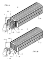
FIG. 2A is a rear (or second end) perspective view of the apparatus illustrated in FIG. 1A;
FIG. 2B is an opposite side perspective view of the apparatus illustrated in FIG. 2A with a rear door open;
FIG. 3A is a perspective view of the apparatus illustrated in FIG. 1A showing a forklift loading the interior with pallets;
FIG. 3B is a perspective view of the apparatus illustrated in FIG. 3A showing a full interior after the forklift has finished loading the last product cart;
FIG. 4A is a perspective view of the apparatus illustrated in FIG. 3A without the fork-lift present;
FIG. 4B is a perspective view of the apparatus illustrated in FIG. 3B showing a full interior without the fork-lift present;
FIG. 5A is a rear (or second end) plan view of the apparatus illustrated in FIGS. 1A and 2A with the rear doors removed;
FIG. 5B is a top cutaway view of the interior of the apparatus illustrated in FIG. 1A;
FIG. 6A is an enlarged perspective view of a product cart used in assisting the loading and unloading of the chamber;
FIG. 6B is a bottom plan view of the product cart illustrated in FIG. 6A;
FIG. 7A is a front plan view of the apparatus illustrated in FIG. 1A with the doors open;
FIG. 7B is an enlarged plan view of a product cart wheel and rail taken at circle 7B of FIG. 7A;
FIG. 8 is a cross-sectional view of the primary floor in the interior of the apparatus of FIG. 1A;
FIG. 9A is a perspective view of a perforated floor section which makes up the primary floor in the interior of the chamber;
FIG. 9B is an enlarged width-wise cross-sectional view of the perforated floor section illustrated in FIG. 9A taken along line 9B—9B;
FIG. 10A is a longitudinal cross-sectional view of the apparatus shown fully loaded with pallets, illustrating one example of the direction of air circulation inside the housing;
FIG. 10B is a longitudinal cross-sectional view of the apparatus illustrating another example of airflow within the chamber;
FIG. 11 is a perspective view of the apparatus illustrated in FIG. 1A attached to a wheel/trailer assembly exhibiting the portability of the apparatus;
FIG. 12A is a perspective view of standard trailer box which can be adapted to produce an apparatus in accordance with the present invention; and
FIG. 12B is a perspective view of the standard trailer box of FIG. 12A mated to a standard trailer assembly.
DETAILED DESCRIPTION OF THE PREFERRED EMBODIMENT
In describing a preferred embodiment of the invention, specific terminology will be selected for the sake of clarity. However, the invention is not intended to be limited to the specific terms so selected, and it is to be understood that each specific term includes all technical equivalents that operate in a similar manner to accomplish a similar purpose.
Certain terminology is used in the following description for convenience only and is not limiting. The terms “right”, “left”, “front”, “rear”, “outer” and “inner” designate relative directions to which reference is made with respect to the observer's relative position while viewing certain drawings. The terminology includes the words above specifically mentioned, derivatives thereof and words of similar import.
Preferred embodiments of the present invention will now be described in detail with reference to the accompanying drawings in which an apparatus for eradicating pests in accordance with the principles of the present invention is generally indicated at 10. Referring to FIG. 1A, the outer housing 12 is illustrated. The housing 12 has a front or first end 14, a rear or second external end 16, an external roof 13 and a rigid base structure 15. The interior volume of the housing is usually referred to herein as the chamber.
The front end 14 of the chamber may be closed off from the outside by a pair of front doors as is illustrated in FIG. 1B. A rectangularly-shaped left door 17 of substantially equal width and height (in one embodiment) as a right door 18 are used to close off the front end of the apparatus. Each of the doors 17, 18 may swing on a plurality of individual hinges or on elongated piano hinges. One or both doors may have a handle 20 and a locking mechanism (not shown).
The doors 17, 18 are preferably insulated. Further, a gasket around the perimeter of each door will reduce the likelihood of heat escaping from the chamber.
As illustrated in FIG. 1B, the apparatus 10 has a left external wall 22 and a right external wall 24. The walls are preferably insulated to ensure a more uniform temperature gradient within the chamber.
The rear or second end 16 of the apparatus 10 is illustrated in FIGS. 2A and 2B. A control panel 48 is shown in FIG. 2A. The control panel 48 houses the circuitry to control the heating means 52. In one embodiment, waste gases created as a by-product of the burning of fossil fuels by the heating means 52 are allowed to escape through port 53.
Left rear door 42 and right rear door 43 provide access to a heater compartment 39 in which the heating means 52 is located. The rear doors 42, 43 may each have one or more ventilation grills 47 therein. The rear or second external end 16 of the apparatus with the doors 42, 43 removed is illustrated in FIG. 5A. A heating means 52 is the device used to heat the air inside the chamber and provides the necessary heat to treat the wood products stored within the chamber. The heating means 52 may be a heater that utilizes electric, gas, oil, wood or other fossil-based fuel. The size (i.e., btu output) of the heater 52 depends on the volume of the chamber and the type of products to be heat-treated.
Referring to FIGS. 5A and 5B, the sub-floor 70 is below a primary floor 50. The sub floor 70 extends—at least partially—under the heater compartment 39. Primary floor 50 has a plurality of perforations, the purpose for which, will be more fully described hereinafter.
The subject apparatus 10 may be used to eradicate pests from a variety of products. Although a number of products (e.g., machinery, food products or other staples, etc.) may be treated by the subject apparatus 10, it is especially well-suited for heat-treating wood products.
Common non-manufactured wood products that the present invention may be particularly adapted to heat-treating are wooden pallets and shipping materials. Accordingly, the present invention is illustrated in various figures as being loaded with wood pallets 98. Other non-manufactured wood products can be handled and treated in a similar manner.
Referring now to FIGS. 3A and 3B, the apparatus 10 may be loaded (in this example with wood pallets 98) through the use of a forklift 99. In this embodiment, left door 17 and right door 18 are opened to allow ingress into and egress from the interior of the apparatus 10.
Referring to FIGS. 4A, 4B and 5B, elongated internal rails 25, 26 are positioned above the primary floor of the interior of the housing. In a preferred embodiment, the internal rails 25, 26 are welded to the inside of the rigid basal structure 15. If an unusually heavy load is routinely treated in the chamber, legs may be added to help support the rails. The elongated internal rails are designed to support and guide a product cart 30. (See FIGS. 6A and 6B.)
A left rail external extension 28 and a right rail external extension 29, as illustrated in FIGS. 3A, 3B, 4A, 4B and 5B, assist in supporting the product carts 30 as the apparatus is being loaded and unloaded. The left rail external extension 28 releasably connects to and is directly aligned with the elongated internal rail 25; similarly, the right rail external extension 29 releasably connects to and is directly aligned with the elongated interior rail 26. The external rail extensions 28, 29 are removed and stored when not in use.
Referring again to FIGS. 4A, 4B, 6A and 6B, the pallets 98 and/or wood products are actually placed on product carts 30. The product carts 30 have a rigid frame 56 to support the products to be heat-treated. The frame 56 is preferably rectangular in shape with the longitudinal dimension corresponding roughly to the width of the chamber. A guide wheel 27 is located preferably at each of the four corners of the frame 56. The guide wheels 27 are designed to roll on the rail external extensions 28, 29 and the elongated interior rails 25, 26 in the chamber. The product cart and rail system greatly assist the loading and unloading of wood products to be heat-treated in the chamber.
In one embodiment, each product cart 30 has a width almost as wide as the width of the chamber. The length of the housing depends on a number of factors; for example, some of the factors to be considered are the area on which the apparatus will be situated, the number of wood products to be treated during one cycle, the dimensions of the wood products to be treated, the mass of the wood products to be treated, etc.
Although the various figures show the cart 30 holding two stacks of pallets, one skilled in the art, after reading this disclosure, could readily adapt the length, width and height of the various elements (chamber, cart, etc.) to accommodate a desired number, type and size of products to be treated. The product carts 30 are designed to be loaded by a human or mechanical power. The carts may also be pushed into or pulled out of the chamber by a person. In another embodiment, the primary floor of the chamber may be reinforced to allow a forklift or other machinery to be brought into the chamber to lift, move, load or unload a particularly heavy or unwieldy load.
Referring again to FIGS. 6A and 6B, guides 55 are designed to accommodate the forks or prongs of the fork lift 99. A plurality of ventilation holes 59 are designed to allow the maximum amount of air to circulate up to the products carried on the carts 30.
Referring now to FIG. 8, a cross section of the primary floor 50 of FIG. 5B is illustrated. A bottom or floor plenum 40 is formed between the sub-floor 70 and the primary floor 50. The floor plenum 40 allows heated air to travel underneath the entire length of the chamber as will be described in further detail hereafter.
Referring now to FIG. 10A, and 10 B ceiling plenum 68 is formed between a sub-ceiling 69 and a primary ceiling 74. The sub-ceiling 69 is made of a substantially flat sheet and stretches across the entire width of the chamber. The sub-ceiling starts from the back wall of the chamber 76 and extends a portion of the way towards the front end 14 of the apparatus. In a preferred embodiment, there are no perforations in the sub-ceiling 69.
Referring now to FIG. 9A, a perforated floor section 62 is shown. A plurality of perforated floor sections 62 are installed in the chamber to form the primary floor 50. The floor sections 62 are perforated in order to allow the heated air to pass from the floor plenum 40 to the product carts 30 and eventually to the products 98 stored on the product carts 30. FIG. 9B is a cross-section of the perforated floor section in FIG. 9A. The length and width of each perforated floor section 62 are relatively unimportant. However, it may be preferable to size each floor section 62 in order for them to be easily moved and lifted by one individual.
Referring again to FIG. 5A an enlarged view of the heater compartment 39 is shown. As stated previously, a forced air heater may be used for the heating means 52 in one embodiment. However, one skilled in the art, after reading this detailed description could readily adapt or substitute other heating means for the forced-air heater. For example, the heating means 52 may be a direct fired heater, either electric or fossil fuel, or an indirect fired heater.
In one embodiment, an exhaust stack 54, connected to port 53 provides a path for the waste gases and combustion by-products generated by the heating means 52 to escape. FIGS. 10A and 10B are longitudinal cross-sectional views of the chamber and include a flow diagram illustrating the path of the air flow within the chamber. The fan assembly 71 circulates through heater 52. In one embodiment the floor plenum 40 is designed to communicate with the output of the heater 52 so that hot air is forced into the floor plenum 40; the hot air rises up through the perforations 63, 65 in the floor sections 62, through the pallets and returned via the ceiling plenum 68.
In the embodiment illustrated in FIG. 10A, the forced heated air travels below the perforated floor sections 62 of the chamber. In the embodiment illustrated in FIG. 10A, the floor plenum 40 is designed to deliver air under the entire floor of the chamber. Since the perforated floor is made up of a plurality of perforated sections 62 having regularly-spaced openings (see FIG. 9A), the heated forced air rises, travels amongst the products and into the ceiling air plenum 68 which directs the air back to the heating means 52.
In the embodiment illustrated in FIG. 10B, the circulation of the air flow is reversed and forced heated air travels through the ceiling plenum 68; the heated air is then drawn substantially evenly through the pallets, through the perforated floor sections 62 and into the floor plenum 40 to be recirculated by the heater 52.
Although the openings in the perforated floor sections 62 are equally-sized and equally-spaced, in one embodiment, the size and spacing of the openings may be varied to ensure that substantially equal air flow passes amongst the products. For example, the perforated floor sections 62 closest to the second end 16 of the chamber may have less openings and/or be spaced further apart than the openings in the perforated floor sections 62 closest to the first end 14.
The sub-ceiling 69 that forms the ceiling air plenum is about three-quarters of the length of the chamber in one preferred embodiment. The length of the sub-ceiling 69, and the shape and number of perforations 63 and 65 in the floor sections 62 ensure that forced hot air moves evenly amongst each stack of products 98. Therefore, the design of the floor plenum, the ceiling plenum and the floor sections 62 ensure that all products 98 within the chamber reach the minimum temperature for the minimum period of time, thereby assuring that the international heat treatment standard can be achieved.
Similarly, in embodiment 10B, the design of the floor return air plenum and ceiling supply plenum ensure that all products 98 within the chamber reach the minimum temperature for the minimum period of times thereby assuring that the international heat treatment standard can be reached.
Tests have proven that the subject apparatus keeps a relatively even temperature distribution throughout the entire chamber without significant hot or cold spots. The present design ensures targeted pests are destroyed and the products are heat-treated properly in a relatively efficient manner without degrading the quality of the products being treated.
In the preferred embodiment a microprocessor based controller can automatically manage the heat treatment process. In this preferred embodiment, a computer is connected to the control panel 48. The control panel 48 communicates with one or more temperature sensors in the chamber in order to control the on/off cycles of the heater 52 and fan assembly 71. By inputting certain parameters, the interior of the chamber can be maintained at a specific temperature for a specific period of time.
Referring now to FIG. 11, the chamber maybe mounted on wheels 97 for moving the chamber to a particular location. A tractor, truck or other towing vehicle (not shown) may be used to pull the apparatus 10. Posts 96 allow the apparatus 10 to be self-supporting when a truck or other vehicle is not present. The system, as shown in FIGS. 12A and 12B, can be constructed from an insulated or non-insulated commercial trailer.
The wheels 97 and posts 96 many be removed, and stored for later use, if the apparatus will be stationed at a particular location for an extended period of time.
Although this invention has been described and illustrated by reference to specific embodiments, it will be apparent to those skilled in the art that various changes and modifications may be made which clearly fall within the scope of this invention. The present invention is intended to be protected broadly within the spirit and scope of the appended claims.

Claims (31)

I claim:
1. A portable apparatus for eradicating pests from both non-manufactured wood and non-manufactured wood products, said apparatus comprising:
a chamber having a first end, a second end, a left wall, a right wall, a ceiling, a partial sub-ceiling, a primary floor, and a sub-floor, said partial sub-ceiling being spaced apart from said ceiling and extending continuously from the second end of the chamber towards the first end of the chamber and terminating at a position short of said first end leaving a portion of the ceiling exposed to the interior of the chamber, the ceiling and sub-ceiling defining a ceiling plenum, and said primary floor being spaced apart from said sub-floor, the primary floor and sub-floor defining a floor plenum, said ceiling plenum and said floor plenum communicating with the interior of the chamber for allowing air to move through the plenums and the interior of the chamber;
a rigid basal structure for supporting said chamber;
a door that allows ingress to and egress from the interior of the chamber, said door positioned at the first end of the chamber;
a means for heating the air in the interior of said chamber, said means of heating communicating with said ceiling plenum and with said floor plenum for moving air heated by said heating means into said chamber and for moving cooler air out of said chamber to be heated by the heating means.
2. The portable apparatus of claim 1 wherein said means for heating comprises a heater and a means for circulating the air within the interior of said chamber.
3. The portable apparatus of claim 2 wherein said heater comprises an indirect fired heating unit.
4. The portable apparatus of claim 2 wherein said heater comprises a direct-fired heating unit.
5. The portable apparatus of claim 2 wherein said heater bums a fossil based fuel (i.e. propane, butane, natural gas, kerosene, diesel fuel, fuel oil).
6. The portable apparatus of claim 2 wherein said heater utilizes an electric heating element.
7. The portable apparatus of claim 2 wherein said means for circulating the air comprises a fan assembly utilizing a fan and electric fan motor.
8. The portable apparatus of claim 7 wherein said fan assembly is a duct axial fan.
9. The portable apparatus of claim 7 wherein said fan assembly is an in-line centrifugal type.
10. The portable apparatus of claim 7 wherein said fan assembly is a backward inclined.
11. The portable apparatus of claim 1 wherein said floor comprises a plurality of floor sections, each section having a plurality of perforations thus providing a means for air to pass freely between said floor plenum and the interior of said chamber.
12. The portable apparatus of claim 1 wherein said means for heating communicates with said plenums proximate the second end of said chamber, and wherein said sub-ceiling is substantially parallel to said ceiling so that air may pass between said ceiling plenum and the interior of said chamber.
13. The portable apparatus of claim 12 wherein said sub-ceiling is formed from a sheet material and extends from the second end three-quarters of the length of the chamber so that the open area comprises an area the width of the chamber by one-quarter of the length of the chamber.
14. The portable apparatus of claim 13 further comprising means for loading and unloading the chamber, said loading and unloading means including:
at least one product cart designed to hold the non-manufactured wood and non-manufactured wood products; and
a left rail positioned inside of said left wall and a right rail positioned inside of said right wall, said rails connected to said rigid basal structure substantially parallel to each other and proximate to the upper part of said basal structure above said floor, said rails extending the length of the chamber and designed to both support and assist with the ingress and egress of the product carts from the chamber.
15. The portable apparatus of claim 14 wherein said product carts have a rigid fabricated structure substantially rectangular in shape and a width slightly less than the width of the chamber, said product carts having a plurality of wheels mounted proximate to the bottom of the structure for riding on said rails.
16. The portable apparatus of claim 15 wherein said loading and unloading means further comprises an external left rail extension that can be removably attached to the left rail and a right rail extension that can be removably attached to the right rail for supporting a product cart outside of said chamber.
17. The portable apparatus of claim 16 wherein said product carts have a slot means proximate to the center and substantially parallel with the underside of said product cart thus providing a means for a lifting machine to move product carts on or off of the rail extensions.
18. The portable apparatus of claim 1 wherein said rigid basal structure is substantially a rectangular steel frame.
19. The portable apparatus of claim 18 wherein said rigid basal structure comprises a plurality of support beams substantially parallel to the first and second ends, attached proximate to the bottom of said basal structure thus providing an additional increase in torsional rigidity along with a means of ingress for lifting machines hence facilitating the portability of the unit.
20. The portable apparatus of claim 1 further comprising a tractor wheel assembly attached to the underside of said basal structure for facilitating the movement and transportation of said chamber.
21. The portable apparatus of claim 20 further comprising means for permanently positioning said chamber at a preferred location.
22. The apparatus of claim 1 wherein said means for heating comprises an inlet for allowing outside air to be heated for make-up air as required to pressurize the interior of the chamber.
23. The portable apparatus of claim 1 wherein said means for heating utilizes steam as a source of heat and transference.
24. A portable apparatus for eradicating pests from both non-manufactured wood and non-manufactured wood products, said apparatus comprising:
a chamber having a first end, a second end, a left wall, a right wall, a ceiling, a partial sub-ceiling, a primary floor, and a sub-floor, said partial sub-ceiling being spaced apart from said ceiling and extending continuously from the second end of the chamber towards the first end of the chamber and terminating at a position short of said first end leaving a portion of the ceiling exposed to the interior of the chamber, the ceiling and sub-ceiling defining a ceiling plenum, and said primary floor being spaced apart from said sub-floor, the primary floor and sub-floor defining a floor plenum, said ceiling plenum and said floor plenum communicating with the interior of the chamber for allowing air to move through the plenums and the interior of the chamber;
a rigid basal structure for supporting said chamber;
a door that allows ingress to and egress from the interior of the chamber, said door positioned at the first end of the chamber;
a heater compartment attached to the second end of the chamber;
a heater located in the heater compartment, the heater having the capacity to heat the air in the interior of said chamber to a desired temperature for a desired period of time, the heater having an inlet and an outlet, the outlet of said heater connected to said floor plenum;
means for circulating air having an inlet and an outlet, the outlet of said circulating air means connected to the inlet of said heater, and the inlet of said circulating air means connected to said ceiling plenum; and
control means for controlling the operation of said heater and said air circulating means so that when a desired temperature and time period are entered into the control means the heater and air circulating means working together to draw air from the chamber into said ceiling plenum and eventually into said air circulating means, said drawn air then pushed into said heater where it is heated to a predetermined temperature, the heated air then being directed into the floor plenum through the perforated floor and into the chamber, thereby keeping the wood products within the chamber at the desired temperature for the desired period of time.
25. The portable apparatus of claim 24 wherein said heater comprises an indirect fired heating unit.
26. The portable apparatus of claim 24 wherein said heater comprises a direct-fired heating unit.
27. The portable apparatus of claim 26 wherein said means for circulating air comprises a fan assembly utilizing a fan and an electric fan motor.
28. The portable apparatus of claim 27 wherein said floor comprises a plurality of floor sections, each section having a plurality of perforations thus providing a means for air to pass freely between said floor plenum and the interior of said chamber.
29. The portable apparatus of claim 28 wherein said sub-ceiling is formed from a sheet substantially parallel to said ceiling, said sub-ceiling extending continuously from the second end of the chamber three-quarters of the way towards the first end of the chamber leaving an open area proximate said first end, said open area having the width of the chamber and one-quarter of the length of the chamber so that air may pass between said ceiling plenum and the interior of said chamber.
30. The portable apparatus of claim 29 further comprising means for loading and unloading the chamber, said loading and unloading means including:
at least one product cart having wheels and designed to hold the non-manufactured wood and non-manufactured wood products; and
a left rail positioned inside of said left wall and a right rail positioned inside of said right wall, said rails connected to said rigid basal structure substantially parallel to each other and proximate to the upper part of said basal structure above said floor, said rails extending the length of the chamber and designed to both support and assist with ingress and egress of the product carts from the chamber.
31. The portable apparatus of claim 30 further comprising a tractor wheel assembly attached to the underside of said basal structure for facilitating the movement and transportation of said chamber.
US10/145,184 2001-05-16 2002-05-14 Apparatus for and method of eradicating pests Expired - Lifetime US6612067B2 (en)

Priority Applications (2)

Application Number Priority Date Filing Date Title
US10/145,184 US6612067B2 (en) 2001-05-16 2002-05-14 Apparatus for and method of eradicating pests
US10/651,583 US20040035044A1 (en) 2001-05-16 2003-08-29 Apparatus for eradicating pests

Applications Claiming Priority (2)

Application Number Priority Date Filing Date Title
US29140701P 2001-05-16 2001-05-16
US10/145,184 US6612067B2 (en) 2001-05-16 2002-05-14 Apparatus for and method of eradicating pests

Related Child Applications (1)

Application Number Title Priority Date Filing Date
US10/651,583 Continuation US20040035044A1 (en) 2001-05-16 2003-08-29 Apparatus for eradicating pests

Publications (2)

Publication Number Publication Date
US20020170227A1 US20020170227A1 (en) 2002-11-21
US6612067B2 true US6612067B2 (en) 2003-09-02

Family

ID=23120164

Family Applications (4)

Application Number Title Priority Date Filing Date
US10/145,184 Expired - Lifetime US6612067B2 (en) 2001-05-16 2002-05-14 Apparatus for and method of eradicating pests
US10/147,745 Abandoned US20030026727A1 (en) 2001-05-16 2002-05-16 Disinfestation apparatus utilizing heat
US10/651,583 Abandoned US20040035044A1 (en) 2001-05-16 2003-08-29 Apparatus for eradicating pests
US11/215,624 Abandoned US20060010791A1 (en) 2001-05-16 2005-08-30 Method for converting a structure into a disinfestation apparatus

Family Applications After (3)

Application Number Title Priority Date Filing Date
US10/147,745 Abandoned US20030026727A1 (en) 2001-05-16 2002-05-16 Disinfestation apparatus utilizing heat
US10/651,583 Abandoned US20040035044A1 (en) 2001-05-16 2003-08-29 Apparatus for eradicating pests
US11/215,624 Abandoned US20060010791A1 (en) 2001-05-16 2005-08-30 Method for converting a structure into a disinfestation apparatus

Country Status (2)

Country Link
US (4) US6612067B2 (en)
CA (2) CA2386678A1 (en)

Cited By (39)

* Cited by examiner, † Cited by third party
Publication number Priority date Publication date Assignee Title
US20030026727A1 (en) * 2001-05-16 2003-02-06 Topp Daniel P. Disinfestation apparatus utilizing heat
US20030200696A1 (en) * 2002-04-26 2003-10-30 Barra Florencio Lazo Method for thermal pest control
US20040028554A1 (en) * 2002-02-20 2004-02-12 Hedman David E. System and process for removing or treating harmful biological and organic substances within an enclosure
US20050202585A1 (en) * 2001-08-20 2005-09-15 Honeywell International, Inc. Micro-machined electromechanical system (mems) accelerometer device having arcuately shaped flexures
US20050220662A1 (en) * 1999-05-28 2005-10-06 Hedman David E Method for removing or treating harmful biological and chemical substances within structures and enclosures
US20050246942A1 (en) * 2004-05-07 2005-11-10 Mueller A C Method of extermination utilizing heated air
US7076915B1 (en) 2001-09-05 2006-07-18 Mills County Technologies, Inc. Apparatus for exterminating an ant colony and method of using the same
US20060185433A1 (en) * 2005-02-18 2006-08-24 Honeywell International, Inc. MEMS teeter-totter accelerometer having reduced non-linearty
US20060242900A1 (en) * 2005-01-05 2006-11-02 Lovelace Reginald B Nematode extermination in place using heat blankets
US20070023980A1 (en) * 2005-07-11 2007-02-01 Mimoun Abaraw Pest control system
US20070062063A1 (en) * 2005-09-07 2007-03-22 Langley Vernon W Mobile mattress sanitizer
US20080014111A1 (en) * 1999-05-28 2008-01-17 Thermapure, Inc. Method for removing or treating harmful biological organisms and chemical substances
US20080127548A1 (en) * 2004-09-02 2008-06-05 Zhangjing Chen Killing Insect Pests Inside Wood By Vacuum Dehydration
WO2008108864A2 (en) * 2006-07-05 2008-09-12 Hedman David E Method for decontaminating objects contaminated with harmful biological agents
US20100024244A1 (en) * 1999-05-20 2010-02-04 Potter Gary J Heater and controls for extraction of moisture and biological organisms from structures
US20100071258A1 (en) * 2008-09-25 2010-03-25 Christopher Molnar Insect eradication system and method
US7765733B1 (en) * 2005-11-01 2010-08-03 The United States Of America As Represented By The Secretary Of Agriculture Ultra-low oxygen treatment for post harvest pest control on agriculture products
US20110064607A1 (en) * 1999-05-28 2011-03-17 Thermapure, Inc. Method for removing or treating harmful biological organisms and chemical substances
US20110064605A1 (en) * 2006-07-05 2011-03-17 Thermapure, Inc. Method for treating an object contaminated with harmful biological organisms or chemical substances utilizing electromagnetic waves
US7908791B1 (en) * 1999-04-20 2011-03-22 Asiaworld Shipping Services Pty Ltd Fumigation apparatus
US20110113674A1 (en) * 2009-10-28 2011-05-19 Th, Inc. Inhibiting Pest Infestation
US7987614B2 (en) * 2004-04-12 2011-08-02 Erickson Robert W Restraining device for reducing warp in lumber during drying
US20120230866A1 (en) * 2009-11-02 2012-09-13 Lance Allen Dear Container treatment
US8272143B1 (en) 2002-02-20 2012-09-25 David Hedman System and process for removing or treating harmful biological and organic substances within structures and enclosures
US20120255219A1 (en) * 2011-04-06 2012-10-11 Technologies Holdings Corp. Self-Contained Heating Unit for Thermal Pest Control
US20120304528A1 (en) * 2011-06-06 2012-12-06 Technologies Holdings Corp. Packaged Terminal Climate Unit for Pest Control
US20120317870A1 (en) * 2011-06-20 2012-12-20 Gregory Allen Pratt Method and apparatus for use in the extermination of bed bug infestations
US20130178240A1 (en) * 2012-01-06 2013-07-11 Fujitsu Mobile Communications Limited Wireless communication terminal device and method of controlling wireless communication terminal device
US8486345B1 (en) 2009-10-23 2013-07-16 Corey S. Westrum Mobile sanitizer unit
US8720109B2 (en) 2011-01-25 2014-05-13 Technologies Holdings Corp. Portable heating system for pest control
US8726539B2 (en) 2012-09-18 2014-05-20 Cambridge Engineering, Inc. Heater and controls for extraction of moisture and biological organisms from structures
US8756857B2 (en) 2011-01-14 2014-06-24 Technologies Holdings Corp. Hydronic heating system and method for pest control
US9226489B2 (en) 2011-03-18 2016-01-05 Ecolab Usa Inc. Heat system for killing pests
US9339021B2 (en) 2012-07-13 2016-05-17 Kenneth Lander Thermal processing device, system, and method
US9554568B1 (en) 2012-04-23 2017-01-31 Jay Tallon System and method for bedbug eradication
US9878762B2 (en) * 2016-03-04 2018-01-30 Fraunhofer-Gesellschaft Zur Foerderung Der Angewandten Forschung E. V. System for launching and recovering an underwater vehicle
US10477853B2 (en) * 2015-06-04 2019-11-19 ZappBug, Inc. Heating chamber system and method for insect extermination
AU2018256565B1 (en) * 2018-06-29 2019-11-21 Kabushiki Kaisha Nihon Yushutsu Jidousha Kensa Center Automobile high-temperature pest extermination device
US20210392870A1 (en) * 2018-11-01 2021-12-23 UNIKAI Lagerei- und Speditionsgesellschaft mbH Apparatus for Heat Treatment of Motor Vehicles or Motor Vehicle Parts

Families Citing this family (14)

* Cited by examiner, † Cited by third party
Publication number Priority date Publication date Assignee Title
US20050013727A1 (en) * 2002-12-05 2005-01-20 Hedman David E. System and process for removing or treating harmful biological and organic substances within an enclosure
US20060180043A1 (en) * 2005-01-28 2006-08-17 Plexus Scientific Corporation System and method for remediation of explosive contamination using convective heat
IT1391705B1 (en) * 2008-11-12 2012-01-27 C I A R T S A S Di Inchingolo Ruggiero & C METHOD FOR THE DISINFESTATION OF WOOD MANUFACTURES
US20110308139A1 (en) * 2009-02-23 2011-12-22 Nuvenco Ip, Llc Pest eradication system
BRPI0901111B1 (en) * 2009-03-05 2021-07-27 Fitolog Controle De Pragas Ltda SYSTEM AND METHOD FOR PHYTOSANITARY THERMAL TREATMENT OF WOODEN AND SIMILAR PACKAGING
US8693855B2 (en) * 2009-05-07 2014-04-08 Cambridge Engineering, Inc Infra-red heater assembly
US20110059412A1 (en) * 2009-09-09 2011-03-10 Thomas Robert Wiedemeier Device and process for eradicating pests in wood
WO2011100297A2 (en) * 2010-02-09 2011-08-18 Cambridge Engineering, Inc. Device for indicating eradication of a pest infestation
GB2504763A (en) * 2012-08-09 2014-02-12 Palletworks Ltd Surface treating a pallet core and spray coating with thermoplastic
ITPG20120041A1 (en) * 2012-10-12 2013-01-11 Fernando Corradini REGENERATIVE TREATMENT ELIMINATES TABLETS AND OTHER INSECTED PARASITES BY SPECIAL HOT CABIN WITH FORCED VENTILATION.
CN104552513B (en) * 2014-12-23 2017-06-13 天津大学 A kind of quarantine of wood fumigation is removed the evil system
US20160249598A1 (en) * 2016-05-02 2016-09-01 Robert Savino Mattress and Furniture Processor
CN107379168B (en) * 2017-08-02 2019-01-04 湖南工程学院 China fir Furniture panel processing unit (plant)
FR3111686B1 (en) * 2020-06-18 2022-12-02 Environnement Services Heat treatment system for cargo container, such as wood logs

Citations (21)

* Cited by examiner, † Cited by third party
Publication number Priority date Publication date Assignee Title
US3811579A (en) * 1972-09-25 1974-05-21 D Black Mechanized van loading and unloading apparatus and system
US4017980A (en) * 1973-04-30 1977-04-19 Kleinguenther Robert A Apparatus and process for treating wood and fibrous materials
US4163038A (en) * 1977-03-03 1979-07-31 Earth Chemical Company, Limited Fumigating method and apparatus
DE3421719A1 (en) * 1984-06-12 1985-12-12 Odenwaldwerke Rittersbach, Kern & Großkinsky GmbH, 6957 Elztal Portable device for decontamination of objects
US4620373A (en) * 1984-07-23 1986-11-04 Laskowski Donald R Dry kiln and method
US4716676A (en) * 1983-09-14 1988-01-05 Masami Imagawa Insect killing system
US4961283A (en) * 1986-08-29 1990-10-09 Charles Forbes Extermination of insects by heat
US5058313A (en) * 1987-01-09 1991-10-22 Tallon Joseph C Method and apparatus for exterminating structure infestations
DE4025828A1 (en) * 1990-08-16 1992-02-20 Automatische Walzenmuehle Heis Pest control in storage or processing buildings - involves holding room temp. between 45 and 65 deg. C. for 12 to 48 hours
US5203108A (en) * 1991-05-31 1993-04-20 Washburn Jr Martin W Method and device for heat killing insects in bulk produce containers
US5447686A (en) * 1994-06-17 1995-09-05 Seidner; Marc A. Method for heat-treating wood and wood products
US5525295A (en) * 1992-05-06 1996-06-11 Despatch Industries Limited Partnership Barrier isolation system
US5607652A (en) * 1993-10-15 1997-03-04 Dornier Gmbh Biological and chemical decontamination chamber
US5789007A (en) * 1996-04-24 1998-08-04 Cool Care, Ltd. Method and apparatus for controlled ripening of fresh produce
US5941233A (en) 1998-08-03 1999-08-24 Rupp Industries, Inc. Indirect-fired heater with regeneration reclaim rotary heat exchanges
US5965185A (en) * 1996-04-24 1999-10-12 Cool Care, Ltd. Transportable and size-adjustable apparatus with multiple air flow control units for ripening of fresh produce
US6141901A (en) 1999-09-14 2000-11-07 Rupp Industries, Inc. Pest control system
US6146600A (en) * 1993-09-17 2000-11-14 University Of Hawaii Side body disingestation chamber
US6171561B1 (en) 1993-09-17 2001-01-09 University Of Hawaii Mechanically loaded direct air circulation commodity disinfestation chamber
US6227002B1 (en) * 1999-08-06 2001-05-08 Cool Care, Ltd. Transportable telescoping cooler
US6319481B1 (en) * 2000-03-14 2001-11-20 Percival C. Banks Sterilization container

Family Cites Families (23)

* Cited by examiner, † Cited by third party
Publication number Priority date Publication date Assignee Title
US1234214A (en) * 1916-09-08 1917-07-24 Mercer Reynolds Insect-eradicator.
US2293931A (en) * 1938-10-31 1942-08-25 Charles B Cook Portable fumigating apparatus
US2239508A (en) * 1938-12-15 1941-04-22 Burgess Battery Co Air-distributing apparatus for ventilating systems
US3814315A (en) * 1972-06-15 1974-06-04 A Dmysh Nose-mounted catalytic cargo trailer and truck body heaters
US4003728A (en) * 1974-10-09 1977-01-18 Eric Rath Method and apparatus for controlling the storage condition of perishable commodities in long-distance transport vehicles
DK156149C (en) * 1980-04-11 1989-11-20 Flaekt Ltd METHOD AND APPARATUS FOR CONDITIONING A SPACE
US4454837A (en) * 1982-11-12 1984-06-19 Moore & Sons, Inc. Truck for transporting boxes of poultry
US4572427A (en) * 1984-03-02 1986-02-25 Mallinckrodt, Inc. Controlled atmosphere enclosure
JPS6236144A (en) * 1985-08-09 1987-02-17 Takenaka Komuten Co Ltd Apparatus for steaming and sterilization of green vegetable
US4640044A (en) * 1985-10-02 1987-02-03 Varnon James W Hood or cover used to eradicate fire ants
US4817329A (en) * 1986-08-29 1989-04-04 Charles Forbes Extermination of insects by heat
US4861095A (en) * 1987-12-08 1989-08-29 American Trailers, Inc. Floor for conditioned air vehicles
DK0489019T3 (en) * 1989-07-19 1995-07-10 Co Ordinated Thermal Syst Method and apparatus for exposing a product to a controlled atmosphere
US5285604A (en) * 1991-10-10 1994-02-15 Tcby Enterprises, Inc. Containerized field kitchen
US5580211A (en) * 1994-09-26 1996-12-03 Mengel; William F. Container transportation system
US5526583A (en) * 1995-01-30 1996-06-18 Hull; Dwayne E. Portable dry kiln for drying or treating lumber
US5809798A (en) * 1996-09-26 1998-09-22 Cornerstone Technologies, Ltd. Refrigerated container with controlled air distribution
DE19709067A1 (en) * 1997-03-06 1998-09-17 Bosch Gmbh Robert Procedure for controlling the air speed in a sterilization tunnel during the heating phase
DE19825880C5 (en) * 1998-06-10 2010-01-07 Binker Materialschutz Gmbh Thermal pest control
US6327812B1 (en) * 1999-05-28 2001-12-11 David Hedman Method of killing organisms and removal of toxins in enclosures
US6513282B2 (en) * 2000-04-28 2003-02-04 Robert Jeffrey Schott Self-contained mobile fumigation chamber system and method
US6612067B2 (en) * 2001-05-16 2003-09-02 Topp Construction Services, Inc. Apparatus for and method of eradicating pests
US6678994B2 (en) * 2001-05-22 2004-01-20 Topp Construction Services, Inc. Sanitary and phytosanitary pest control method by controlled application of heat

Patent Citations (23)

* Cited by examiner, † Cited by third party
Publication number Priority date Publication date Assignee Title
US3811579A (en) * 1972-09-25 1974-05-21 D Black Mechanized van loading and unloading apparatus and system
US4017980A (en) * 1973-04-30 1977-04-19 Kleinguenther Robert A Apparatus and process for treating wood and fibrous materials
US4163038A (en) * 1977-03-03 1979-07-31 Earth Chemical Company, Limited Fumigating method and apparatus
US4716676A (en) * 1983-09-14 1988-01-05 Masami Imagawa Insect killing system
DE3421719A1 (en) * 1984-06-12 1985-12-12 Odenwaldwerke Rittersbach, Kern & Großkinsky GmbH, 6957 Elztal Portable device for decontamination of objects
US4620373A (en) * 1984-07-23 1986-11-04 Laskowski Donald R Dry kiln and method
US4961283A (en) * 1986-08-29 1990-10-09 Charles Forbes Extermination of insects by heat
US5058313A (en) * 1987-01-09 1991-10-22 Tallon Joseph C Method and apparatus for exterminating structure infestations
DE4025828A1 (en) * 1990-08-16 1992-02-20 Automatische Walzenmuehle Heis Pest control in storage or processing buildings - involves holding room temp. between 45 and 65 deg. C. for 12 to 48 hours
US5203108A (en) * 1991-05-31 1993-04-20 Washburn Jr Martin W Method and device for heat killing insects in bulk produce containers
US5203108B1 (en) * 1991-05-31 1999-06-08 Martin W Washburn Jr Method and device for heat killing insects in bulk produce containers
US5525295A (en) * 1992-05-06 1996-06-11 Despatch Industries Limited Partnership Barrier isolation system
US6146600A (en) * 1993-09-17 2000-11-14 University Of Hawaii Side body disingestation chamber
US6447737B1 (en) * 1993-09-17 2002-09-10 Michael R. Williamson Mechanically loaded direct air circulation commodity disinfestation chamber
US6171561B1 (en) 1993-09-17 2001-01-09 University Of Hawaii Mechanically loaded direct air circulation commodity disinfestation chamber
US5607652A (en) * 1993-10-15 1997-03-04 Dornier Gmbh Biological and chemical decontamination chamber
US5447686A (en) * 1994-06-17 1995-09-05 Seidner; Marc A. Method for heat-treating wood and wood products
US5965185A (en) * 1996-04-24 1999-10-12 Cool Care, Ltd. Transportable and size-adjustable apparatus with multiple air flow control units for ripening of fresh produce
US5789007A (en) * 1996-04-24 1998-08-04 Cool Care, Ltd. Method and apparatus for controlled ripening of fresh produce
US5941233A (en) 1998-08-03 1999-08-24 Rupp Industries, Inc. Indirect-fired heater with regeneration reclaim rotary heat exchanges
US6227002B1 (en) * 1999-08-06 2001-05-08 Cool Care, Ltd. Transportable telescoping cooler
US6141901A (en) 1999-09-14 2000-11-07 Rupp Industries, Inc. Pest control system
US6319481B1 (en) * 2000-03-14 2001-11-20 Percival C. Banks Sterilization container

Cited By (69)

* Cited by examiner, † Cited by third party
Publication number Priority date Publication date Assignee Title
US7908791B1 (en) * 1999-04-20 2011-03-22 Asiaworld Shipping Services Pty Ltd Fumigation apparatus
US20100024244A1 (en) * 1999-05-20 2010-02-04 Potter Gary J Heater and controls for extraction of moisture and biological organisms from structures
US20080014111A1 (en) * 1999-05-28 2008-01-17 Thermapure, Inc. Method for removing or treating harmful biological organisms and chemical substances
US20110219665A1 (en) * 1999-05-28 2011-09-15 Hedman David E Method for removing or treating harmful biological and chemical substances within structures and enclosures
US20110064607A1 (en) * 1999-05-28 2011-03-17 Thermapure, Inc. Method for removing or treating harmful biological organisms and chemical substances
US20050220662A1 (en) * 1999-05-28 2005-10-06 Hedman David E Method for removing or treating harmful biological and chemical substances within structures and enclosures
US7837932B2 (en) 1999-05-28 2010-11-23 Thermapure, Inc. Method for removing or treating harmful biological organisms and chemical substances
US8256135B2 (en) 1999-05-28 2012-09-04 Thermapure, Inc. Method for removing or treating harmful biological and chemical substances within structures and enclosures
US8852501B2 (en) 1999-05-28 2014-10-07 Thermapure, Inc. Method for removing or treating harmful biological and chemical substances within structures and enclosures
US20060010791A1 (en) * 2001-05-16 2006-01-19 Topp Construction Services, Inc. Method for converting a structure into a disinfestation apparatus
US20030026727A1 (en) * 2001-05-16 2003-02-06 Topp Daniel P. Disinfestation apparatus utilizing heat
US20040035044A1 (en) * 2001-05-16 2004-02-26 Topp Daniel P. Apparatus for eradicating pests
US20050202585A1 (en) * 2001-08-20 2005-09-15 Honeywell International, Inc. Micro-machined electromechanical system (mems) accelerometer device having arcuately shaped flexures
US20060248784A1 (en) * 2001-09-05 2006-11-09 Rodney Spies Method for exterminating an ant colony
US7076915B1 (en) 2001-09-05 2006-07-18 Mills County Technologies, Inc. Apparatus for exterminating an ant colony and method of using the same
US7363746B2 (en) 2001-09-05 2008-04-29 Mills County Technologies, Inc. Method for exterminating an ant colony
US20040028554A1 (en) * 2002-02-20 2004-02-12 Hedman David E. System and process for removing or treating harmful biological and organic substances within an enclosure
US8272143B1 (en) 2002-02-20 2012-09-25 David Hedman System and process for removing or treating harmful biological and organic substances within structures and enclosures
US8221678B2 (en) 2002-02-20 2012-07-17 Hedman David E System and process for removing or treating harmful biological and organic substances within an enclosure
US7134239B2 (en) * 2002-04-26 2006-11-14 Florencio Lazo Barra Method for thermal pest control
US20030200696A1 (en) * 2002-04-26 2003-10-30 Barra Florencio Lazo Method for thermal pest control
US7987614B2 (en) * 2004-04-12 2011-08-02 Erickson Robert W Restraining device for reducing warp in lumber during drying
US20050246942A1 (en) * 2004-05-07 2005-11-10 Mueller A C Method of extermination utilizing heated air
US20080127548A1 (en) * 2004-09-02 2008-06-05 Zhangjing Chen Killing Insect Pests Inside Wood By Vacuum Dehydration
US7739829B2 (en) * 2004-09-02 2010-06-22 Virginia Tech Intellectual Properties, Inc. Killing insect pests inside wood by vacuum dehydration
US20060242900A1 (en) * 2005-01-05 2006-11-02 Lovelace Reginald B Nematode extermination in place using heat blankets
US7469500B2 (en) * 2005-01-05 2008-12-30 Lovelace Reginald B Nematode extermination in place using heat blankets
US20060185433A1 (en) * 2005-02-18 2006-08-24 Honeywell International, Inc. MEMS teeter-totter accelerometer having reduced non-linearty
US20070023980A1 (en) * 2005-07-11 2007-02-01 Mimoun Abaraw Pest control system
US20070062063A1 (en) * 2005-09-07 2007-03-22 Langley Vernon W Mobile mattress sanitizer
US7765733B1 (en) * 2005-11-01 2010-08-03 The United States Of America As Represented By The Secretary Of Agriculture Ultra-low oxygen treatment for post harvest pest control on agriculture products
US20110064605A1 (en) * 2006-07-05 2011-03-17 Thermapure, Inc. Method for treating an object contaminated with harmful biological organisms or chemical substances utilizing electromagnetic waves
WO2008108864A2 (en) * 2006-07-05 2008-09-12 Hedman David E Method for decontaminating objects contaminated with harmful biological agents
WO2008108864A3 (en) * 2006-07-05 2008-12-24 David E Hedman Method for decontaminating objects contaminated with harmful biological agents
US7926222B2 (en) * 2008-09-25 2011-04-19 Molnar Christopher J Insect eradication system and method
US20100071258A1 (en) * 2008-09-25 2010-03-25 Christopher Molnar Insect eradication system and method
US8486345B1 (en) 2009-10-23 2013-07-16 Corey S. Westrum Mobile sanitizer unit
US20110113674A1 (en) * 2009-10-28 2011-05-19 Th, Inc. Inhibiting Pest Infestation
US20120230866A1 (en) * 2009-11-02 2012-09-13 Lance Allen Dear Container treatment
US9539623B2 (en) * 2009-11-02 2017-01-10 Lance Allen Dear Container treatment
US8756857B2 (en) 2011-01-14 2014-06-24 Technologies Holdings Corp. Hydronic heating system and method for pest control
US9237742B2 (en) 2011-01-25 2016-01-19 Technologies Holdings Corp. Portable heating system and method for pest control
US9992990B2 (en) 2011-01-25 2018-06-12 Therma-Stor LLC Portable heating system and method for pest control
US9807994B2 (en) 2011-01-25 2017-11-07 Technologies Holdings Corp. Portable heating system and method for pest control
US8720109B2 (en) 2011-01-25 2014-05-13 Technologies Holdings Corp. Portable heating system for pest control
US9930878B2 (en) 2011-01-25 2018-04-03 Therma-Stor LLC Portable heating system and method for pest control
US9578867B2 (en) 2011-01-25 2017-02-28 Technologies Holding Corp. Portable heating system and method for pest control
US10051853B2 (en) 2011-01-25 2018-08-21 Therma-Stor LLC Portable heating system and method for pest control
US9374991B2 (en) 2011-01-25 2016-06-28 Technologies Holdings Corp. Portable heating system and method for pest control
US11013226B2 (en) 2011-03-18 2021-05-25 Ecolab Usa Inc. Heat system for killing pests
US9226489B2 (en) 2011-03-18 2016-01-05 Ecolab Usa Inc. Heat system for killing pests
US10070639B2 (en) 2011-03-18 2018-09-11 Ecolab Usa Inc. Heat system for killing pests
US11737445B2 (en) 2011-03-18 2023-08-29 Ecolab Usa Inc. Heat system for killing pests
US8479439B2 (en) * 2011-04-06 2013-07-09 Technologies Holding Corp. Self-contained heating unit for thermal pest control
US20120255219A1 (en) * 2011-04-06 2012-10-11 Technologies Holdings Corp. Self-Contained Heating Unit for Thermal Pest Control
US8479440B2 (en) * 2011-04-06 2013-07-09 Technologies Holdings Corp. Self-contained heating unit for thermal pest control
US9247725B2 (en) * 2011-06-06 2016-02-02 Technologies Holdings Corp. Packaged terminal climate unit for pest control
US20120304528A1 (en) * 2011-06-06 2012-12-06 Technologies Holdings Corp. Packaged Terminal Climate Unit for Pest Control
US10159239B2 (en) * 2011-06-06 2018-12-25 Therma-Stor LLC Packaged terminal climate unit for pest control
US20150000185A1 (en) * 2011-06-20 2015-01-01 Gregory Allen Pratt Method for use in the extermination of bed bug infestations
US20120317870A1 (en) * 2011-06-20 2012-12-20 Gregory Allen Pratt Method and apparatus for use in the extermination of bed bug infestations
US20130178240A1 (en) * 2012-01-06 2013-07-11 Fujitsu Mobile Communications Limited Wireless communication terminal device and method of controlling wireless communication terminal device
US9554568B1 (en) 2012-04-23 2017-01-31 Jay Tallon System and method for bedbug eradication
US9339021B2 (en) 2012-07-13 2016-05-17 Kenneth Lander Thermal processing device, system, and method
US8726539B2 (en) 2012-09-18 2014-05-20 Cambridge Engineering, Inc. Heater and controls for extraction of moisture and biological organisms from structures
US10477853B2 (en) * 2015-06-04 2019-11-19 ZappBug, Inc. Heating chamber system and method for insect extermination
US9878762B2 (en) * 2016-03-04 2018-01-30 Fraunhofer-Gesellschaft Zur Foerderung Der Angewandten Forschung E. V. System for launching and recovering an underwater vehicle
AU2018256565B1 (en) * 2018-06-29 2019-11-21 Kabushiki Kaisha Nihon Yushutsu Jidousha Kensa Center Automobile high-temperature pest extermination device
US20210392870A1 (en) * 2018-11-01 2021-12-23 UNIKAI Lagerei- und Speditionsgesellschaft mbH Apparatus for Heat Treatment of Motor Vehicles or Motor Vehicle Parts

Also Published As

Publication number Publication date
US20060010791A1 (en) 2006-01-19
CA2386678A1 (en) 2002-11-16
CA2386602A1 (en) 2002-11-16
US20040035044A1 (en) 2004-02-26
US20020170227A1 (en) 2002-11-21
US20030026727A1 (en) 2003-02-06

Similar Documents

Publication Publication Date Title
US6612067B2 (en) Apparatus for and method of eradicating pests
US20090211148A1 (en) Mobil Pest Eradication System
US20070084105A1 (en) Portable pest control system
US6588140B1 (en) Pest control system
US6678994B2 (en) Sanitary and phytosanitary pest control method by controlled application of heat
US7837932B2 (en) Method for removing or treating harmful biological organisms and chemical substances
US20110154686A1 (en) Apparatus and method for treating a commodity
US20070062063A1 (en) Mobile mattress sanitizer
AU2020100411B4 (en) Vapour heat treatment apparatus and method
WO2008006035A2 (en) Method for removing or treating harmful biological organisms and chemical substances
EP1600172B1 (en) Device for disinfesting and drying wooden packaging material
US6776003B1 (en) Container
CN110260609A (en) A kind of industrial chemicals intelligent vacuum drying case
JP2000116301A (en) Device for controlling insect pest or the like, and control of insect pest or the like by using the same
US20110059412A1 (en) Device and process for eradicating pests in wood
WO2008082368A1 (en) Article processing system and method
KR101672755B1 (en) Pressure Resistance Type Fumigation Facility for Fruit Sterilization
KR102561021B1 (en) Cart tunnel dryer for food drying and food drying method using the same
AU2016331029B2 (en) Portable shipping container contents heating apparatus
CN211861581U (en) Novel scattered or centralized automobile heating dry steaming equipment
US20160249598A1 (en) Mattress and Furniture Processor
US20160273837A1 (en) Heat Treatment of Firewood
CA3083482A1 (en) Device and process for eradicating pests in wood
JPH0679533B2 (en) Fumigation equipment
CN110973092A (en) Novel scattered or centralized automobile heating dry steaming equipment

Legal Events

Date Code Title Description
AS Assignment

Owner name: TOPP CONSTRUCTION SERVICES, INC., PENNSYLVANIA

Free format text: ASSIGNMENT OF ASSIGNORS INTEREST;ASSIGNOR:TOPP, DANIEL P.;REEL/FRAME:012999/0020

Effective date: 20020605

STCF Information on status: patent grant

Free format text: PATENTED CASE

FPAY Fee payment

Year of fee payment: 4

FPAY Fee payment

Year of fee payment: 8

AS Assignment

Owner name: SUNBELT RENTALS, INC., SOUTH CAROLINA

Free format text: MERGER;ASSIGNOR:TOPP CONSTRUCTION SERVICES, INC.;REEL/FRAME:028451/0387

Effective date: 20120402

FPAY Fee payment

Year of fee payment: 12