US6508560B2 - Display apparatus with corrosion-resistant light directing film - Google Patents
Display apparatus with corrosion-resistant light directing film Download PDFInfo
- Publication number
- US6508560B2 US6508560B2 US10/028,345 US2834501A US6508560B2 US 6508560 B2 US6508560 B2 US 6508560B2 US 2834501 A US2834501 A US 2834501A US 6508560 B2 US6508560 B2 US 6508560B2
- Authority
- US
- United States
- Prior art keywords
- layer
- display apparatus
- protective layer
- metal layer
- polymer
- Prior art date
- Legal status (The legal status is an assumption and is not a legal conclusion. Google has not performed a legal analysis and makes no representation as to the accuracy of the status listed.)
- Expired - Fee Related
Links
Images


Classifications
-
- G—PHYSICS
- G02—OPTICS
- G02F—OPTICAL DEVICES OR ARRANGEMENTS FOR THE CONTROL OF LIGHT BY MODIFICATION OF THE OPTICAL PROPERTIES OF THE MEDIA OF THE ELEMENTS INVOLVED THEREIN; NON-LINEAR OPTICS; FREQUENCY-CHANGING OF LIGHT; OPTICAL LOGIC ELEMENTS; OPTICAL ANALOGUE/DIGITAL CONVERTERS
- G02F1/00—Devices or arrangements for the control of the intensity, colour, phase, polarisation or direction of light arriving from an independent light source, e.g. switching, gating or modulating; Non-linear optics
- G02F1/01—Devices or arrangements for the control of the intensity, colour, phase, polarisation or direction of light arriving from an independent light source, e.g. switching, gating or modulating; Non-linear optics for the control of the intensity, phase, polarisation or colour
- G02F1/13—Devices or arrangements for the control of the intensity, colour, phase, polarisation or direction of light arriving from an independent light source, e.g. switching, gating or modulating; Non-linear optics for the control of the intensity, phase, polarisation or colour based on liquid crystals, e.g. single liquid crystal display cells
- G02F1/133—Constructional arrangements; Operation of liquid crystal cells; Circuit arrangements
- G02F1/1333—Constructional arrangements; Manufacturing methods
- G02F1/1335—Structural association of cells with optical devices, e.g. polarisers or reflectors
- G02F1/133553—Reflecting elements
-
- G—PHYSICS
- G02—OPTICS
- G02F—OPTICAL DEVICES OR ARRANGEMENTS FOR THE CONTROL OF LIGHT BY MODIFICATION OF THE OPTICAL PROPERTIES OF THE MEDIA OF THE ELEMENTS INVOLVED THEREIN; NON-LINEAR OPTICS; FREQUENCY-CHANGING OF LIGHT; OPTICAL LOGIC ELEMENTS; OPTICAL ANALOGUE/DIGITAL CONVERTERS
- G02F1/00—Devices or arrangements for the control of the intensity, colour, phase, polarisation or direction of light arriving from an independent light source, e.g. switching, gating or modulating; Non-linear optics
- G02F1/01—Devices or arrangements for the control of the intensity, colour, phase, polarisation or direction of light arriving from an independent light source, e.g. switching, gating or modulating; Non-linear optics for the control of the intensity, phase, polarisation or colour
- G02F1/13—Devices or arrangements for the control of the intensity, colour, phase, polarisation or direction of light arriving from an independent light source, e.g. switching, gating or modulating; Non-linear optics for the control of the intensity, phase, polarisation or colour based on liquid crystals, e.g. single liquid crystal display cells
- G02F1/133—Constructional arrangements; Operation of liquid crystal cells; Circuit arrangements
- G02F1/1333—Constructional arrangements; Manufacturing methods
- G02F1/133345—Insulating layers
-
- G—PHYSICS
- G02—OPTICS
- G02F—OPTICAL DEVICES OR ARRANGEMENTS FOR THE CONTROL OF LIGHT BY MODIFICATION OF THE OPTICAL PROPERTIES OF THE MEDIA OF THE ELEMENTS INVOLVED THEREIN; NON-LINEAR OPTICS; FREQUENCY-CHANGING OF LIGHT; OPTICAL LOGIC ELEMENTS; OPTICAL ANALOGUE/DIGITAL CONVERTERS
- G02F1/00—Devices or arrangements for the control of the intensity, colour, phase, polarisation or direction of light arriving from an independent light source, e.g. switching, gating or modulating; Non-linear optics
- G02F1/01—Devices or arrangements for the control of the intensity, colour, phase, polarisation or direction of light arriving from an independent light source, e.g. switching, gating or modulating; Non-linear optics for the control of the intensity, phase, polarisation or colour
- G02F1/13—Devices or arrangements for the control of the intensity, colour, phase, polarisation or direction of light arriving from an independent light source, e.g. switching, gating or modulating; Non-linear optics for the control of the intensity, phase, polarisation or colour based on liquid crystals, e.g. single liquid crystal display cells
- G02F1/133—Constructional arrangements; Operation of liquid crystal cells; Circuit arrangements
- G02F1/1333—Constructional arrangements; Manufacturing methods
- G02F1/1335—Structural association of cells with optical devices, e.g. polarisers or reflectors
- G02F1/133504—Diffusing, scattering, diffracting elements
-
- G—PHYSICS
- G02—OPTICS
- G02F—OPTICAL DEVICES OR ARRANGEMENTS FOR THE CONTROL OF LIGHT BY MODIFICATION OF THE OPTICAL PROPERTIES OF THE MEDIA OF THE ELEMENTS INVOLVED THEREIN; NON-LINEAR OPTICS; FREQUENCY-CHANGING OF LIGHT; OPTICAL LOGIC ELEMENTS; OPTICAL ANALOGUE/DIGITAL CONVERTERS
- G02F2202/00—Materials and properties
- G02F2202/02—Materials and properties organic material
- G02F2202/022—Materials and properties organic material polymeric
Definitions
- the present invention is directed to a light directing arrangement and method for use with a display apparatus, and more particularly to a light directing arrangement that is resistant to corrosion and directs an image to an angle different from a glare angle.
- LCD Liquid crystal displays
- One class of LCD which is substantially reflective, often includes a reflector for directing ambient light to the viewer.
- Another class of LCD often includes a partially transmissive reflector for also allowing light from a light source within the device to convey information to the viewer.
- a partially transmissive reflector is commonly called a transflector, and an LCD that incorporates a transflector is commonly called transflective.
- the reflector may be made of metal or other types of composite materials.
- the present invention is a display apparatus that provides protection against corrosion for a metallic layer.
- the display apparatus includes a light modulating layer sandwiched between two polarizers and a light directing film.
- the light directing film includes a prismatic structure including saw-tooth formations having tilted surfaces, and a metal layer on the side of the prismatic substrate having the saw-tooth formations. The tilt angle of the tilted surfaces offsets an optimal viewing angle for the display from a glare angle for the display.
- the display apparatus may also include a light cavity for providing light to the light modulating layer, adjacent to the prismatic polymer substrate, wherein the metal layer is partially transmissive.
- the tilted surfaces of the prismatic layer may have a tilt angle of about 1° to 35° from horizontal, more preferably about 3° to 12° from horizontal and most preferably about 6° to 9° from horizontal, in one application.
- the saw-tooth formations may have a repeat distance of about 5 microns or more and about 200 microns or less, more preferably about 30 microns or more and about 80 microns or less, and most preferably about 50 microns, for one application.
- a polymer protective layer is formed over the metal layer to protect the metal layer from corrosion.
- the light directing film also includes a diffuse adhesive layer formed over the polymer layer, attached to the polarizer.
- the polymer protective layer protects the metal layer from the mobile reactive species in the adhesive layer.
- the polymer protective layer may be selected from a group consisting of cross-linked epoxy, cross-linked or linear acrylic resin, soluble polyester, polyethylene, polyvinylidene chloride, polyvinyl alcohol and polymethyl methacrylate.
- the polymer protective layer may be formed by solution coating in a preferred embodiment, in which case the thickness can range from about 0.01 micron to about 50 microns.
- the polymer protective layer may be formed by the vapor deposition and subsequent curing of a polymer precursor onto the metal layer.
- the protective layer may be cured using a process selected from the group of thermal radiation, ultraviolet radiation, electron beam radiation, plasma exposure and corona exposure.
- the polymer protective layer may have a thickness of about 1 nanometer to 2 micrometers.
- the polymer protective layer may be formed by a plasma process selected from the group consisting of plasma-polymerization and plasma-enhanced chemical vapor deposition.
- the polymer protective layer is a solution coated polymethyl methacrylate.
- the metal layer is a silver layer having a thickness of about 400 Angstroms.
- the diffuse adhesive layer may preferably be butyl acrylate acrylic acid adhesive.
- the display apparatus of the present invention may include both the inorganic protective layer and the polymer protective layer.
- FIG. 1 is a cross-sectional view of a display apparatus of one embodiment of the present invention, including a light directing film.
- FIG. 2 is a cross-sectional view of a display apparatus of another embodiment of the present invention, including a light directing film and a light cavity.
- FIG. 3 is a cross-sectional view of one embodiment of a light directing film of the present invention, before incorporation into a display apparatus.
- FIG. 4 is a cross-sectional view of a second embodiment of a light directing film of the present invention.
- FIG. 5 illustrates time versus reflectivity during weathering for a silver/indium tin oxide film.
- FIG. 6 illustrates time versus reflectivity during weathering of a silver/zinc sulfide film.
- FIG. 7 illustrates the transmission spectra for a silver/indium tin oxide coating on a light directing film.
- FIG. 8 shows the reflection spectra for a silver/indium tin oxide coating on a light directing film.
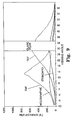
- FIG. 9 illustrates the reflectance of an LCD versus the viewing angle for four different types of LCDs, where each LCD incorporates a different type of transflector.
- FIG. 10 is a cross-sectional view of another embodiment of a light directing film of the present invention.
- FIG. 11 is a cross-sectional view of another embodiment of a light directing film of the present invention.
- FIG. 12 is a cross-sectional view of another embodiment of a light directing film of the present invention.
- FIG. 13 is a cross-sectional view of another embodiment of a light directing film of the present invention.
- the present invention is believed to be applicable to a variety of systems and arrangements that direct light away from a glare angle and inhibit corrosion of a reflective or transflective metal layer in a display.
- the invention has been found to be particularly advantageous in application environments where a transflective display is needed, that is, a display that is capable of being illuminated by an ambient light source or by a light source within the display. While the present invention is not so limited, an appreciation of the various aspects of the invention is best gained through a discussion of the various application examples operating in such an environment.
- FIG. 1 illustrates a cross-section of one particular embodiment of a display 10 of the present invention including a lens or touch screen 14 .
- the lens or touch screen 14 may receive input from the user of the display, or may contribute specific optical qualities to the display.
- the display further includes a light modulating layer 20 , made up of a top polarizer 22 , a liquid crystal layer 24 , and a bottom polarizer 26 . Further, a light directing film 28 is attached to the bottom polarizer 26 .
- the light directing film of the present invention may also be incorporated into a display device that includes only one polarizer, although it will more commonly be used in a device having two polarizers that sandwich the liquid crystal layer.
- the light directing film 28 is provided to steer the image toward a desired viewing angle, which is substantially different than a glare angle of the display 10 .
- the structure of the light directing film 28 is discussed in detail below.
- the light directing film 28 may also be referred to as a beam steering film or tilted mirror film.
- an ambient light source 30 is illustrated, producing incoming ambient light rays 32 .
- a light ray 32 from source 30 is incident on the display apparatus at angle a from the normal.
- the normal is the direction perpendicular to the display surface.
- a portion of the incoming light will be reflected as glare, illustrated by glare ray 34 , by the top surface of the display apparatus 10 .
- the glare ray 34 has a glare angle, b, from the normal.
- the glare image will be visible over a range of viewing angles, but will have a peak brightness at glare angle b.
- Angle a is equal to angle b, according to the law of reflection.
- the light directing film 28 is designed to direct the image ray 38 so that it will emerge from the display 10 at an angle from the normal that is substantially different than the glare angle b.
- the display image will also be visible over a range of viewing angles, and will have a peak brightness at a narrower range of viewing angles, centered around an “optimal viewing angle.” In FIG. 1, the peak image angle or optimal viewing angle is nearly normal to the display, as represented by image ray 38 . As a result, a viewer of the display apparatus 10 at position 44 can view the display image clearly without interference from the glare image.
- FIG. 2 illustrates an alternate display device 200 of the present invention, wherein components that are similar to the embodiment of FIG. 1 have identical reference numbers.
- Display device 200 includes a light cavity 50 , for providing light to the light modulating layer 24 and illuminating the display apparatus 200 .
- the light cavity 50 includes a light source 52 and a reflector 54 .
- the light cavity 50 may be configured in many different arrangements, to direct light 60 toward the light modulating layer 20 .
- the light cavity 50 may be an edge-illuminated light guide, an electroluminescent panel, or one of many other light cavity arrangements that are known in the art.
- FIG. 3 shows a more detailed view of the cross section of one embodiment of a tilted mirror film or light directing film 300 , before it is incorporated into a display device.
- the light directing film includes a silicone liner 310 , a pressure sensitive adhesive 314 , an optional polymer protective layer 316 , an optional inorganic protective layer 318 , and a metal layer 320 .
- the metal layer 320 provides a reflective surface for reflecting the ambient light toward the light modulating layer to produce a display image.
- the silicone liner 310 may be provided on the light directing film 300 to cover the adhesive 314 . The silicone liner 310 is removed before the pressure sensitive adhesive 314 is attached to the bottom polarizer 26 .
- the metal layer 320 is formed on a prismatic structure 322 , that is adjacent to a polymer substrate 324 .
- the words “formed on” or “formed over” will be used to refer to a layer that is formed on top of, but not necessarily directly adjacent to, another layer. Accordingly, the metal layer may not be directly adjacent to the prismatic structure. Intervening layers could be present.
- a protective liner 326 may be adjacent to the polymer substrate 324 , on the side opposite from the metal layer 320 , if needed, to protect the polymer substrate during shipping or after incorporation into the display apparatus.
- the prismatic structure 322 includes two sides, where one side 328 includes saw tooth formations 329 having tilted surfaces 330 .
- a second side 332 of the prismatic structure 322 is preferably substantially smooth or planar.
- the prismatic structure 322 is configured to direct the display image ray 38 to emerge from the display apparatus at an angle substantially different from the glare ray 34 , which has an angle b from the normal.
- the prismatic layer 322 includes tilted surfaces 330 .
- the tilted surfaces are configured so that the peak, or greatest brightness, of the display image occurs at an angle that is different than the peak viewing angle of the glare image.
- the typical viewer will orient the display at about 30° from horizontal.
- the viewer's eyes will be at about 10° from the normal.
- the ambient light source is assumed to be directly overhead. Therefore the ambient light is incident on the display at an angle a, which is said to be ⁇ 30° from the display normal.
- the glare image will then have a peak at about 30° from the display normal.
- the light directing film of the present invention functions to direct the display image to an optimal viewing angle, or peak brightness angle, that is substantially different from the glare angle.
- the optimal viewing angle would be substantially different from 30° away from the normal.
- the display will function to redirect the peak brightness angle to be different than the glare angle in situations where the incidence angle is not ⁇ 30° from normal. There will be a functional relationship between the light incidence angle and the peak brightness angle.
- the tilted surfaces 330 have a tilt angle t of about 1° to 35° from horizontal in one embodiment.
- the tilted surfaces have a tilt angle of about 3° to 12° from horizontal.
- the tilt angle t will be about 6-9° from the horizontal.
- the repeat distance of the saw tooth formations 329 it is desirable for the repeat distance of the saw tooth formations 329 , to be small enough so that the saw tooth formations are not perceptible to the human eye at the typical viewing distance.
- the repeat distance may also be defined as the horizontal distance between saw tooth formations.
- the saw tooth formations should be large enough to be capable of being reliably formed. The smaller the formation, the more difficult the production procedures for manufacturing the prismatic layer.
- the repeat distance in one embodiment ranges from about 5 microns or more to about 200 microns or less. More preferably, the repeat distance may range from 30 microns to about 80 microns. Most preferably, the saw tooth formations have a repeat distance of about 50 microns. However, where the display is much larger and viewed from a greater distance, such as for a billboard or roadside sign, the repeat distance may be substantially larger.
- the prismatic structure may include a cured resin, an embossable, thermoplastic material, or another material capable of forming the saw tooth formations and having the desired optical properties.
- the prismatic structure is formed of a cured resin, such as a cross-linked epoxy-acrylate.
- the prismatic structure 322 provides smooth surfaces for metal deposition, and has excellent adhesion to both the polymer substrate 324 and to the metal layer 320 .
- the prismatic structure is preferably pinhole free.
- the composition of the prismatic structure 322 is preferably highly transmissive of visible light, scratch resistant, and has low outgassing.
- the resin retains the saw tooth form without shrinkage when cured and when exposed to heat and humidity.
- the material of the prismatic structure is non-halogenated, more preferably non-brominated because halogen agents, especially bromine, may cause corrosion of the metal layer.
- a cross-linked epoxy acrylate that is preferred for use in the prismatic structure is a UV curable composition including the following components, which are listed with a range of percentage weight: bisphenol-A epoxy diacrylate (55-80%), methyl styrene (5-25%), acrylated epoxy (1-10%), a photoinitiator (0.25-5%) (such as Lucirin TPO), and fluorosurfactant (0.1-0.3%). Further, the composition may or may not include a second photoinitiator, such as Irgacure 184, at a percentage weight up to 5%.
- a second photoinitiator such as Irgacure 184
- a halogen agent heavier than flourine is an advantage because of the corrosive effect of some halogen agents on some metals, particularly on silver.
- the fluorosurfactant is a halogen, it is relatively inert, present in only small quantities, and at least partially evaporates when the metal layer is formed on the prismatic layer.
- the presence of the methyl styrene may contribute to the favorable adhesion characteristics with the polymer substrate and with the metal layer.
- This composition provides the advantages mentioned above, and also changes the mechanical properties of the metal surface, making it less brittle. This composition is more completely described in a co-pending U.S. patent application titled “Compositions and Structures Made Therefrom”, having Ser. No. 09/425,270, filed on the same date as the present application.
- the saw tooth formations 329 can be formed in the prismatic structure 322 by many different methods known in the art, such as applying the resin structure between a substrate and a tool having saw tooth formations and polymerizing the composition under UV radiation, then separating the sheet from the tool. Other formation methods are also known and may be utilized in the present invention. Assuming that the apex angle is 90°, the thickness of the prismatic structure from a peak to a valley can be determined based on the repeat distance(r) and tilt angle (t), where:
- a prismatic structure with a 6-7° tilt angle and a 50 micron repeat distance may have a peak to valley thickness in the range of 5-7 microns.
- the prismatic structure Positioned as a base to the triangle portions of the saw tooth formations, the prismatic structure may include a “land portion” that is a flat layer component underneath the triangle portions.
- the prismatic structure 322 of the embodiment of FIG. 3 has a land portion below the dashed line within the prismatic layer 322 .
- the embodiments of FIGS. 10-11 also include a land portion 1018 or 1118 of the prismatic structure 1012 or 1112 , below the dashed line.
- the land portion of the prismatic structure may be in the range of 0 to 3 microns, and may depend on the process used to form the prismatic structure.
- the land portion of the prismatic structure has a thickness of about 0.5 microns.
- the metal layer 320 is formed on the saw tooth formations 328 of the prismatic structure 322 .
- the metal layer 320 is preferably highly reflective, and partially transmissive.
- the transmissivity of the metallic layer 320 makes it possible to use a light cavity 50 in the display apparatus, as illustrated in FIG. 2 .
- the metal layer may be composed of many different materials capable of forming reflective layers including, one or more of: silver, chromium, nickel, aluminum, titanium, aluminum-titanium alloy, gold, zirconium, platinum, palladium, aluminum-chromium alloy or rhodium.
- the metal layer may be formed on the prismatic substrate using many different methods that are known in the art, including vacuum deposition or plating.
- Suitable vacuum deposition techniques include sputtering, evaporation and cathodic arc deposition.
- Plating techniques such as electroplating or solution plating could also be used.
- the metal layer 320 may have a thickness greater than or equal to about 25 angstroms and less than or equal to about 3000 angstroms. Preferably, the metal layer has a relatively uniform thickness.
- the metal layer is partially transmissive, allowing light from an internal light cavity to illuminate the display.
- the most preferred materials for a partially transmissive metallic layer are silver and aluminum, because of their reflective and transmissive qualities as thin layers. Silver is most preferred for its low light absorption, meaning that the sum of the reflectivity and the transmissivity of silver is high compared to other materials.
- the metal layer is a silver layer of about 400 angstroms.
- Silver is vulnerable to attack by airborne pollutants and solid borne ions, reactive monomers and solvents. Airborne pollutants that may attack silver include compounds from tail pipe emissions and the components of acid rain, especially those including sulfur.
- silver is more transmissive than aluminum in the blue visible light range. While aluminum appears neutral in color, silver has a yellowish cast.
- other metals are also vulnerable to corrosion and other types of damage and have color characteristics that favor a particular color.
- one embodiment of the present invention includes an inorganic protective layer 318 formed on the metal layer, where the inorganic protective layer inhibits molecular transfer to the metal layer.
- the inorganic protective layer 318 preferably balances the color of the light that is reflected and transmitted by the metal layer 320 .
- Preferred materials for the inorganic protective layer include indium tin oxide (ITO), zinc sulfide (ZnS), tin oxide, indium oxide and titanium oxide. Where these materials are used, in combination with a silver layer, where a colorless reflectance and transmission spectra is desired, the inorganic protective layer may have a thickness greater than or equal to about 300 angstroms and less than or equal to about 1000 angstroms.
- inorganic protective layer do provide protection for the metal layer at thinner layers, but the color correction properties may also be considered when determining the thickness of the inorganic protective layer.
- Silver metal reflectivity is higher at the red end of the visible spectrum than the blue end.
- Use of ITO, ZnS, or other dielectric materials on the silver will shift the relative reflectivity as a function of wavelength so that the reflected light is redder, bluer or more neutral, depending on the dielectric thickness, than is seen with the native silver reflectivity. This color shifting first occurs in the thickness range of 300 angstroms to 1000 angstroms, and repeats at higher order thickness'.
- any color correction requirements are preferably considered when determining the thickness of the inorganic protective layer.
- the inorganic protective layer include titanium and its oxides, where the layer would have a thickness greater than or equal to about 10 angstroms and less than or equal to about 3000 angstroms.
- the inorganic protective layer 318 may be selected from the group consisting of silicon dioxide, silicon monoxide, and magnesium fluoride, with a thickness of greater than or equal to about 300 angstroms and less than or equal to about 1500 angstroms.
- Other metals and alloys, their oxides and suboxides can be used where the material is deposited from the metallic source and is oxidized by subsequent exposure, such as titanium.
- ITO demonstrates the most favorable properties for use as the inorganic protective layer on a silver metal layer.
- Zinc sulfide and titanium are also preferred materials for use as the inorganic protective layer in some devices.
- tie layer or nucleation layer on one or both sides adjacent to the metal layer, to improve film formation.
- Some examples of commonly used tie layers include titanium, chromium, zirconium, nickel iron chromium or other alloys.
- silver is used as the metal layer and ITO or ZnS is used as the inorganic protective layer, the use of a tie layer did not substantially improve the performance of the light directing film.
- FIG. 5 shows the reflection change during weathering of a silver layer coated with ITO. Accelerated environmental tests were carried out for ITO/Ag films with a constant Ag thickness of 33 nm and varied ITO thicknesses of 8 nm, 15 nm, and 38 nm. The ITO/Ag films were coated with a pressure sensitive adhesive with diffusing properties and were then laminated to glass. The samples were then placed in an environment with a temperature of 65° C. and 95% relative humidity, and the reflectance of the samples were measured at regular intervals. Most ITO/Ag films were found to be quite protective.
- FIG. 6 shows the reflection change of a silver and ZnS layer during accelerated environmental tests.
- a silver coating with a constant thickness of 33 nm was combined with varied ZnS thicknesses of 33 nm, 43 nm, and 83 nm.
- the Ag/ZnS films were coated with a pressure sensitive adhesive with diffusing properties and were then laminated to glass. The samples were then placed in an environment with a temperature of 65° C. and 95% relative humidity. The thickest ZnS films offered protection. However, the performance of the ZnS films was not as good as the protection provided by the ITO films.
- FIG. 7 shows the transmission spectra for an ITO/Ag coating on a light directing film with a fixed silver thickness of 50 nm and varied ITO thicknesses of approximately 30 nm, 40 nm, 55 nm, and 75 nm.
- a variation of the ITO thickness changes the transmitted color of the full construction.
- FIG. 8 shows the reflection spectra for an ITO/Ag coating on a light directing film with the same qualities as the film used for FIG. 7 . Again, a variation of the ITO thickness changed the reflected color of the full construction.
- the transmission spectra was measured without the adhesive layer.
- the pressure sensitive adhesive 314 is preferably an optically diffuse layer.
- the pressure sensitive adhesive layer includes an acrylate acrylic acid adhesive.
- the adhesive 314 may include optical diffuser particles, dispersed throughout the adhesive layer to improve the diffusive properties of the adhesive layer.
- the adhesive layer may inhibit corrosion and other damage of the metal layer, by providing a deterrent to the migration of molecules between the bottom polarizer 26 and the metal layer 320 .
- the polarizer may contain halogens and other reactants, that may migrate to the metal layer 320 , causing corrosion and other damage.
- iodine may migrate to the metal layer from the polarizer causing corrosion.
- the adhesive deters the migration of molecules including iodine to the metallic layer, thereby extending the lifetime of the metallic layer 320 .
- the pressure sensitive adhesive may be of the type butyl acrylate/acrylic acid, having a ratio between 90/10 and 97/3, iso-octyl acrylate acrylic acid having a ratio between 90/10 and 97/3, or iso-octyl acrylate/acrylic acid/isobornyl acrylate/Regalrez 6108 having a ratio of approximately 66.3/0.67/13.4/19.3.
- the adhesive may be used in combination with one or more of bisamide cross-linker, benzoyl peroxide initiator, an aziridine cross-linker, a chlorinated cross-linker such as XL-330, Irgacure 651 cross-linker, or other standard acrylic adhesive cross-linkers.
- the adhesive may contain one or more of the following additives: benzotriazole, 5-amino benzotriazole, 5-butyl benzotriazole, benzotriazole 5-carboxylic acid, octadecyl thiol, or thiosilanes.
- benzotriazole 5-amino benzotriazole, 5-butyl benzotriazole, benzotriazole 5-carboxylic acid, octadecyl thiol, or thiosilanes.
- a pressure sensitive adhesive that may be used with the present invention is described in PCT WO 99/21913, which is hereby incorporated by reference.
- the diffusive quality of the pressure sensitive adhesive layer may be adjusted by modifying the concentration of diffusing particles suspended within the adhesive, depending on the specific level of diffusion that is desired.
- the light directing film 300 includes a polymer barrier layer or polymer protective layer 316 , formed on the inorganic protective layer 318 .
- the polymer protective layer 316 inhibits molecular transfer to the metal layer 320 in this embodiment.
- the polymer protective layer may or may not be used in combination with the inorganic protective layer.
- the polymer protective layer or polymer layer 316 is selected from a group consisting of cross-linked epoxy resin, cross-linked or linear acrylic resin, epoxy acrylate, polyester such as Vitel®, polyethylene, polyvinylidene chloride, and polyvinyl alcohol.
- a cross-linked acrylic resin that may be used has the tradename B48N, produced by Rohm and Haas, 100 Independence Mall West, Philadelphia, Pa. 19106-2399.
- the polymer protective layer 316 will typically be deposited on the inorganic protective layer, as illustrated in FIG. 3 .
- the polymer protective layer is typically deposited directly onto the metal layer. The construction of such an arrangement would be similar to the construction of FIG. 3, if the inorganic protective layer 318 were eliminated.
- the polymer protective layer may be formed using a variety of methods known in the art.
- the polymer protective layer is preferably solution coated, in which case the thickness of the polymer protective layer 316 may range from about 0.01 micron to about 50 microns.
- the polymer protective layer may be conformally deposited on the metal layer or inorganic protective layer, or may planarize or partially planarize the underlying saw tooth formations.
- the polymer protective layer 316 has a planarizing function
- one side of the layer has tilted surfaces corresponding to the tilted surfaces of the prismatic structure, and a second side of the layer 316 is substantially planar.
- the polymer protective layer 316 may include more than one layer.
- the polymer protective layer may include more than one layer.
- more than one layer may be desirable to ensure that the polymer protective layer functions as a proper barrier.
- One possible method for forming the polymer protective layer 316 is vapor depositing volatile monomeric or oligomeric polymer precursors, then curing the precursors.
- the deposition may take place at normal atmospheric pressure or under vacuum. Curing may be accomplished using either thermal, ultraviolet, or electron beam radiation, or plasma or corona exposure.
- One example of such a method for conformal deposition and some examples of specific materials are described in co-pending applications U.S. Ser. No. 09/259,100, titled “Retroreflective Articles Having Polymer Multilayer Reflective Coatings” and U.S. Ser. No.
- a typical polymer protective layer would have a thickness of about 1 nm to about 2 micron. In some embodiments, this method may be preferred to solution coating the polymer protective layer, because the solvent used in solution coating may be detrimental to the metal layer or other layers of the display apparatus.
- the polymer protective layer could also be deposited using plasma processes such as plasma polymerization or plasma-enhanced chemical vapor deposition, as is known in the art.
- the polymer protective layer is solution-coated polymethyl methacrylate (PMMA) with a thickness of about 10 microns.
- PMMA may include additives such as UV blockers and tarnish-inhibiting agents.
- One preferred additive to the PMMA is glycol dimercaptoacetate (GDA), a corrosion inhibitor for silver.
- GDA glycol dimercaptoacetate
- the polymer protective layer could include the UV-curable cross-linked epoxy acrylate described above as the preferred material for the prismatic structure.
- the polymer substrate may be a material selected from the group consisting of PET, polyether sulphone (PES), polycarbonate, cellulose diacetate, and cellulose triacetate, and may be birefringent or non-birefringent.
- the polymer substrate has a thickness of about 25 to 1000 microns.
- FIG. 9 illustrates the advantage of including a light directing film in a display apparatus.
- FIG. 9 plots the reflected light profile, showing reflected luminescence measured in foot lamberts (fL) versus viewing angle, for four different LCD's. The four LCD's are identical except that a different transflector is used. The incident light was collimated and directed at ⁇ 30 degrees to the normal.
- a light directing film of one embodiment of the present invention was utilized.
- the TMF was attached to the bottom polarizer of a light modulating layer, similar to the device illustrated in FIG. 1 .
- the TMF film included a polymer substrate, a polymer prismatic layer, a silver layer and a polymer protective layer of PMMA.
- the TMF was adhered to the back polarizer of the LCD.
- the Holographic film is a reflective film formed by the action of interfering laser beams on a photoactive medium. It reflects light at a designed angle different from the glare direction, but has a hue of a single color, usually green.
- Imagix® film manufactured by Polaroid Corporation.
- the Standard transflector is a composite material formed from an adhesive matrix and a reflective particulate adhered to a clear substrate, for example using the trade name NPF-EG4225P3, manufactured by Nitto Denko.
- the TDF film is a 3M product comprising a diffusing adhesive coated on one side of a reflective polarizer substrate and a neutral density film coated on the back side of the substrate. TDF replaces the bottom polarizer of a reflective display, while the Holographic film and the Standard transflector adhere to the back surface of a dichroic bottom display polarizer.
- the glare peak for the display is at about 28-36°.
- the standard, Holographic and TDF samples have brightness peaks during ambient mode performance near this glare peak.
- the TMF sample of the present invention has a brightness peak substantially different than this glare peak, however, at about 12°.
- the incident light was at ⁇ 30° from normal incidence during the testing.
- the light directing film of FIG. 2 may be constructed in many different ways, and still accomplish the re-direction of the image angle away from the glare angle, protect the metal film from corrosion and other damage, and balance color of the reflected and transmitted light.
- FIGS. 10-13 Four different construction examples are shown in FIGS. 10-13.
- a light directing film 1000 is illustrated including a polymer film substrate 1010 , a cured prismatic polymer layer 1012 , a metal layer 1014 , and an adhesive layer 1016 .
- the prismatic layer 1012 includes a land portion 1018 , as previously discussed, below the dashed line through the prismatic structure.
- the adhesive layer 1016 planarizes, or back-fills the saw tooth formations of the prismatic layer 1012 .
- the adhesive layer 1016 may or may not contain the optical diffuser particles that are illustrated in this embodiment.
- the light directing film 1000 attaches to the bottom polarizer of a reflective LCD using adhesive layer 1016 .
- the light directing film 1000 will also include at least one additional layer adjacent to the metal layer 1014 , according to the invention, such as an inorganic protective layer, a polymer protective layer, or both, that are not illustrated in FIG. 10 .
- FIG. 11 shows a cross-section of a light directing film 1100 , including a polymer film substrate 1110 , a cured prismatic polymer layer 1112 , a metal layer 1114 , and a cured polymer layer 1116 .
- the prismatic layer 1112 includes a land portion 1118 , as previously discussed, below the dashed line through the prismatic structure.
- the cured polymer layer 1116 may planarize or back-fill the saw tooth formations, and may or may not contain optical diffuser particles.
- the light directing film 1100 may be positioned in a display apparatus with the cured polymer layer 1116 adjacent to the bottom polarizer of a reflective LCD and may be bonded with an adhesive native to the polarizer.
- the pressure sensitive adhesive is resident within the polarizer.
- the light directing film 1100 will also include at least one additional layer adjacent to the metal layer 1114 , according to the invention, such as an inorganic protective layer, a polymer protective layer, or both, that are not illustrated in FIG. 11 .
- FIG. 12 illustrates another embodiment of a light directing film 1200 of the present invention.
- the light directing film includes a cured polymer layer 1210 , a cured prismatic polymer layer 1214 , which may or may not contain optical diffuser particles, a metal layer 1212 , and a polymer film substrate 1216 .
- the optical diffuser particles are present within the prismatic layer 1214 , rather than in the adhesive layer.
- the optical diffuser particles might also be included in other layers of the construction, such as the polymer protective layer, that are between the metal layer and the ambient light source.
- the metal layer 1212 is formed on the cured prismatic polymer layer 1214 , and the cured polymer layer 1210 back-fills the prisms.
- the light directing film 1200 is positioned with the substrate 1216 adjacent to the bottom polarizer of a reflective LCD and may be bonded with an adhesive native to the polarizer. Therefore, in this embodiment, the pressure sensitive adhesive is included within the polarizer.
- the light directing film 1200 will also include at least one additional layer adjacent to the metal layer 1212 , according to the invention, such as an inorganic protective layer, a polymer protective layer, or both, that are not illustrated in FIG. 12 .
- FIG. 13 shows a light directing film 1300 including a polymer film substrate 1310 , which may or may not contain optical diffuser particles, a metal layer 1312 formed on the polymer film substrate 1310 , and a cured polymer layer 1314 , which back-fills the saw tooth formations.
- the diffusing characteristic is provided by the polymer film substrate 1310 rather than by the adhesive layer.
- the light directing film 1300 is positioned with the polymer film substrate 1310 adjacent to the bottom polarizer of a reflective LCD and may be bonded with an adhesive native to the polarizer. Therefore, in this embodiment, the pressure sensitive adhesive is included within the polarizer.
- the embodiment of FIG. 13 will also include at least one additional layer adjacent to the metal layer 1312 , according to the invention, such as an inorganic protective layer, a polymer protective layer, or both, that are not illustrated in FIG. 13
- This invention provides a reflective or transflective optical film multilayer construction that can serve as a component of an information display device, such as an LCD in a cellular telephone.
- Back reflectors and transflectors, and other light control elements in such devices are subjected to high heat and/or humidity conditions in field use and in product qualification.
- Similar constructions using thin metal films as the reflective/transflective layer failed under these conditions by losing reflectivity or optical density.
- the variants of the light directing film listed below have been tested and can survive harsh environmental conditions.
- the following compositions showed only negligible degradation of transmissivity and reflectivity after being subjected to 65° C. at 95% relative humidity for at least 240 hours.
- the reflectivity averaged over the visible spectrum suffered less than 3% degradation during the environmental tests.
- These compositions were attached to a polarizer during testing.
- an inorganic protective layer of about 500 angstroms zinc sulfide
- the present invention is applicable to a number of different LCDs including reflective layers. Accordingly, the present invention should not be considered limited to the particular examples described above, but rather should be understood to cover all aspects of the invention as set out in the attached claims. Various modifications, equivalent processes, as well as numerous structures to which the present invention may be applicable will be readily apparent to those of skill in the art upon review of the present specification. The claims are intended to cover such modifications and devices.
Abstract
The present invention is a display apparatus that provides protection against damage for a metallic layer. The display apparatus includes a light modulating layer, a polarizer, and a light directing film. The light directing film includes a prismatic structure including saw tooth formations having tilted surfaces and a metal layer on the side of the prismatic substrate having the saw-tooth formations. A tilt angle of the tilted surfaces offsets an optimal viewing angle for the display from a glare angle for the display. The light directing film of the display apparatus of the present invention includes a polymer protective layer formed over the metal layer to protect the metal layer from damage. The light directing film also includes a diffuse adhesive layer formed over the polymer layer, attached to the polarizer. The polymer protective layer protects the metal layer from the adhesive layer. The display apparatus may include both the inorganic protective layer and the polymer protective layer, in one embodiment.
Description
This application is a continuation of Ser. No. 09/834,164, filed Apr. 12, 2001, now issued as U.S. Pat. No. 6,357,880, issued on Mar. 19, 2002, which is a divisional of application Ser. No. 09/425,765, filed Oct. 22, 1999, now U.S. Pat. No. 6,264,336, issued on Jul. 24, 2001, which applications are both incorporated herein by reference in their entireties.
The present invention is directed to a light directing arrangement and method for use with a display apparatus, and more particularly to a light directing arrangement that is resistant to corrosion and directs an image to an angle different from a glare angle.
Liquid crystal displays (LCD) are used in many different types of electronic devices, including portable computers, cellular phones, and digital watches. One class of LCD, which is substantially reflective, often includes a reflector for directing ambient light to the viewer. Another class of LCD often includes a partially transmissive reflector for also allowing light from a light source within the device to convey information to the viewer. A partially transmissive reflector is commonly called a transflector, and an LCD that incorporates a transflector is commonly called transflective. The reflector may be made of metal or other types of composite materials. Some examples of LCD devices are discussed in co-pending application, “Optical Devices Using Reflecting Polarizing Materials”, Ser. No. 09/298,003, filed Apr. 22, 1999.
The present invention is a display apparatus that provides protection against corrosion for a metallic layer. The display apparatus includes a light modulating layer sandwiched between two polarizers and a light directing film. The light directing film includes a prismatic structure including saw-tooth formations having tilted surfaces, and a metal layer on the side of the prismatic substrate having the saw-tooth formations. The tilt angle of the tilted surfaces offsets an optimal viewing angle for the display from a glare angle for the display.
The display apparatus may also include a light cavity for providing light to the light modulating layer, adjacent to the prismatic polymer substrate, wherein the metal layer is partially transmissive.
The tilted surfaces of the prismatic layer may have a tilt angle of about 1° to 35° from horizontal, more preferably about 3° to 12° from horizontal and most preferably about 6° to 9° from horizontal, in one application. The saw-tooth formations may have a repeat distance of about 5 microns or more and about 200 microns or less, more preferably about 30 microns or more and about 80 microns or less, and most preferably about 50 microns, for one application.
In one embodiment of the present application, a polymer protective layer is formed over the metal layer to protect the metal layer from corrosion. The light directing film also includes a diffuse adhesive layer formed over the polymer layer, attached to the polarizer. The polymer protective layer protects the metal layer from the mobile reactive species in the adhesive layer. The polymer protective layer may be selected from a group consisting of cross-linked epoxy, cross-linked or linear acrylic resin, soluble polyester, polyethylene, polyvinylidene chloride, polyvinyl alcohol and polymethyl methacrylate.
The polymer protective layer may be formed by solution coating in a preferred embodiment, in which case the thickness can range from about 0.01 micron to about 50 microns. Alternatively, the polymer protective layer may be formed by the vapor deposition and subsequent curing of a polymer precursor onto the metal layer. The protective layer may be cured using a process selected from the group of thermal radiation, ultraviolet radiation, electron beam radiation, plasma exposure and corona exposure. In the case of formation using vapor deposition, the polymer protective layer may have a thickness of about 1 nanometer to 2 micrometers.
Alternatively, the polymer protective layer may be formed by a plasma process selected from the group consisting of plasma-polymerization and plasma-enhanced chemical vapor deposition. Preferably, the polymer protective layer is a solution coated polymethyl methacrylate. Preferably, the metal layer is a silver layer having a thickness of about 400 Angstroms. The diffuse adhesive layer may preferably be butyl acrylate acrylic acid adhesive.
The display apparatus of the present invention may include both the inorganic protective layer and the polymer protective layer.
The invention may be more completely understood by considering the detailed description of various embodiments of the invention that follows in connection with the accompanying drawings.
FIG. 1 is a cross-sectional view of a display apparatus of one embodiment of the present invention, including a light directing film.
FIG. 2 is a cross-sectional view of a display apparatus of another embodiment of the present invention, including a light directing film and a light cavity.
FIG. 3 is a cross-sectional view of one embodiment of a light directing film of the present invention, before incorporation into a display apparatus.
FIG. 4 is a cross-sectional view of a second embodiment of a light directing film of the present invention.
FIG. 5 illustrates time versus reflectivity during weathering for a silver/indium tin oxide film.
FIG. 6 illustrates time versus reflectivity during weathering of a silver/zinc sulfide film.
FIG. 7 illustrates the transmission spectra for a silver/indium tin oxide coating on a light directing film.
FIG. 8 shows the reflection spectra for a silver/indium tin oxide coating on a light directing film.
FIG. 9 illustrates the reflectance of an LCD versus the viewing angle for four different types of LCDs, where each LCD incorporates a different type of transflector.
FIG. 10 is a cross-sectional view of another embodiment of a light directing film of the present invention.
FIG. 11 is a cross-sectional view of another embodiment of a light directing film of the present invention.
FIG. 12 is a cross-sectional view of another embodiment of a light directing film of the present invention.
FIG. 13 is a cross-sectional view of another embodiment of a light directing film of the present invention.
While the invention is amenable to various modifications and alternative forms, specifics thereof have been shown by way of example in the drawings and will be described in detail. It should be understood, however, that the intention is not to limit the invention to particular embodiments described. On the contrary, the intention is to cover all modifications, equivalents, and alternatives falling within the spirit and scope of the invention as defined by the appended claims.
The present invention is believed to be applicable to a variety of systems and arrangements that direct light away from a glare angle and inhibit corrosion of a reflective or transflective metal layer in a display. The invention has been found to be particularly advantageous in application environments where a transflective display is needed, that is, a display that is capable of being illuminated by an ambient light source or by a light source within the display. While the present invention is not so limited, an appreciation of the various aspects of the invention is best gained through a discussion of the various application examples operating in such an environment.
FIG. 1 illustrates a cross-section of one particular embodiment of a display 10 of the present invention including a lens or touch screen 14. The lens or touch screen 14 may receive input from the user of the display, or may contribute specific optical qualities to the display. The display further includes a light modulating layer 20, made up of a top polarizer 22, a liquid crystal layer 24, and a bottom polarizer 26. Further, a light directing film 28 is attached to the bottom polarizer 26. The light directing film of the present invention may also be incorporated into a display device that includes only one polarizer, although it will more commonly be used in a device having two polarizers that sandwich the liquid crystal layer. The light directing film 28 is provided to steer the image toward a desired viewing angle, which is substantially different than a glare angle of the display 10. The structure of the light directing film 28 is discussed in detail below. The light directing film 28 may also be referred to as a beam steering film or tilted mirror film.
In FIG. 1, an ambient light source 30 is illustrated, producing incoming ambient light rays 32. In this illustration, a light ray 32 from source 30 is incident on the display apparatus at angle a from the normal. The normal is the direction perpendicular to the display surface. A portion of the incoming light will be reflected as glare, illustrated by glare ray 34, by the top surface of the display apparatus 10. The glare ray 34 has a glare angle, b, from the normal. The glare image will be visible over a range of viewing angles, but will have a peak brightness at glare angle b. Angle a is equal to angle b, according to the law of reflection. Another portion of the incoming light will pass through the light modulating layer 20 and be reflected by the light directing film 28, as the display information or image, represented by image ray 38. The light directing film 28 is designed to direct the image ray 38 so that it will emerge from the display 10 at an angle from the normal that is substantially different than the glare angle b. The display image will also be visible over a range of viewing angles, and will have a peak brightness at a narrower range of viewing angles, centered around an “optimal viewing angle.” In FIG. 1, the peak image angle or optimal viewing angle is nearly normal to the display, as represented by image ray 38. As a result, a viewer of the display apparatus 10 at position 44 can view the display image clearly without interference from the glare image.
FIG. 2 illustrates an alternate display device 200 of the present invention, wherein components that are similar to the embodiment of FIG. 1 have identical reference numbers. Display device 200 includes a light cavity 50, for providing light to the light modulating layer 24 and illuminating the display apparatus 200. The light cavity 50 includes a light source 52 and a reflector 54. The light cavity 50 may be configured in many different arrangements, to direct light 60 toward the light modulating layer 20. For example, the light cavity 50 may be an edge-illuminated light guide, an electroluminescent panel, or one of many other light cavity arrangements that are known in the art.
FIG. 3 shows a more detailed view of the cross section of one embodiment of a tilted mirror film or light directing film 300, before it is incorporated into a display device. The light directing film includes a silicone liner 310, a pressure sensitive adhesive 314, an optional polymer protective layer 316, an optional inorganic protective layer 318, and a metal layer 320. The metal layer 320 provides a reflective surface for reflecting the ambient light toward the light modulating layer to produce a display image. The silicone liner 310 may be provided on the light directing film 300 to cover the adhesive 314. The silicone liner 310 is removed before the pressure sensitive adhesive 314 is attached to the bottom polarizer 26.
The metal layer 320 is formed on a prismatic structure 322, that is adjacent to a polymer substrate 324. Throughout the text, the words “formed on” or “formed over” will be used to refer to a layer that is formed on top of, but not necessarily directly adjacent to, another layer. Accordingly, the metal layer may not be directly adjacent to the prismatic structure. Intervening layers could be present.
A protective liner 326 may be adjacent to the polymer substrate 324, on the side opposite from the metal layer 320, if needed, to protect the polymer substrate during shipping or after incorporation into the display apparatus. The prismatic structure 322 includes two sides, where one side 328 includes saw tooth formations 329 having tilted surfaces 330. A second side 332 of the prismatic structure 322 is preferably substantially smooth or planar.
The prismatic structure 322 is configured to direct the display image ray 38 to emerge from the display apparatus at an angle substantially different from the glare ray 34, which has an angle b from the normal. In order to accomplish the redirection of the image, the prismatic layer 322 includes tilted surfaces 330. The tilted surfaces are configured so that the peak, or greatest brightness, of the display image occurs at an angle that is different than the peak viewing angle of the glare image.
It is helpful to consider the orientation of a typical viewer of an LCD. For many LCDs in hand-held devices, the typical viewer will orient the display at about 30° from horizontal. The viewer's eyes will be at about 10° from the normal. The ambient light source is assumed to be directly overhead. Therefore the ambient light is incident on the display at an angle a, which is said to be −30° from the display normal. The glare image will then have a peak at about 30° from the display normal. The light directing film of the present invention functions to direct the display image to an optimal viewing angle, or peak brightness angle, that is substantially different from the glare angle. In the preceding example, the optimal viewing angle would be substantially different from 30° away from the normal. Of course, the display will function to redirect the peak brightness angle to be different than the glare angle in situations where the incidence angle is not −30° from normal. There will be a functional relationship between the light incidence angle and the peak brightness angle.
In order to accomplish the redirection of the optimal viewing angle, the tilted surfaces 330 have a tilt angle t of about 1° to 35° from horizontal in one embodiment. Preferably, the tilted surfaces have a tilt angle of about 3° to 12° from horizontal. Most preferably, the tilt angle t will be about 6-9° from the horizontal. These preferred tilt angles are determined based on the typical viewer scenario mentioned above, and are also dependent on the qualities of a particular LCD.
In many applications, it is desirable for the repeat distance of the saw tooth formations 329, to be small enough so that the saw tooth formations are not perceptible to the human eye at the typical viewing distance. The repeat distance may also be defined as the horizontal distance between saw tooth formations. However, the saw tooth formations should be large enough to be capable of being reliably formed. The smaller the formation, the more difficult the production procedures for manufacturing the prismatic layer. In a hand-held LCD with a typical viewing distance of about 40 to 60 cm, the repeat distance in one embodiment ranges from about 5 microns or more to about 200 microns or less. More preferably, the repeat distance may range from 30 microns to about 80 microns. Most preferably, the saw tooth formations have a repeat distance of about 50 microns. However, where the display is much larger and viewed from a greater distance, such as for a billboard or roadside sign, the repeat distance may be substantially larger.
The prismatic structure may include a cured resin, an embossable, thermoplastic material, or another material capable of forming the saw tooth formations and having the desired optical properties. Preferably, the prismatic structure is formed of a cured resin, such as a cross-linked epoxy-acrylate. Preferably, the prismatic structure 322 provides smooth surfaces for metal deposition, and has excellent adhesion to both the polymer substrate 324 and to the metal layer 320. The prismatic structure is preferably pinhole free. The composition of the prismatic structure 322 is preferably highly transmissive of visible light, scratch resistant, and has low outgassing. Preferably, the resin retains the saw tooth form without shrinkage when cured and when exposed to heat and humidity. Further, preferably the material of the prismatic structure is non-halogenated, more preferably non-brominated because halogen agents, especially bromine, may cause corrosion of the metal layer.
One example of a cross-linked epoxy acrylate that is preferred for use in the prismatic structure is a UV curable composition including the following components, which are listed with a range of percentage weight: bisphenol-A epoxy diacrylate (55-80%), methyl styrene (5-25%), acrylated epoxy (1-10%), a photoinitiator (0.25-5%) (such as Lucirin TPO), and fluorosurfactant (0.1-0.3%). Further, the composition may or may not include a second photoinitiator, such as Irgacure 184, at a percentage weight up to 5%. The lack of a significant amount of a halogen agent heavier than flourine is an advantage because of the corrosive effect of some halogen agents on some metals, particularly on silver. Although the fluorosurfactant is a halogen, it is relatively inert, present in only small quantities, and at least partially evaporates when the metal layer is formed on the prismatic layer. The presence of the methyl styrene may contribute to the favorable adhesion characteristics with the polymer substrate and with the metal layer. This composition provides the advantages mentioned above, and also changes the mechanical properties of the metal surface, making it less brittle. This composition is more completely described in a co-pending U.S. patent application titled “Compositions and Structures Made Therefrom”, having Ser. No. 09/425,270, filed on the same date as the present application.
The saw tooth formations 329 can be formed in the prismatic structure 322 by many different methods known in the art, such as applying the resin structure between a substrate and a tool having saw tooth formations and polymerizing the composition under UV radiation, then separating the sheet from the tool. Other formation methods are also known and may be utilized in the present invention. Assuming that the apex angle is 90°, the thickness of the prismatic structure from a peak to a valley can be determined based on the repeat distance(r) and tilt angle (t), where:
For example, a prismatic structure with a 6-7° tilt angle and a 50 micron repeat distance, may have a peak to valley thickness in the range of 5-7 microns. Positioned as a base to the triangle portions of the saw tooth formations, the prismatic structure may include a “land portion” that is a flat layer component underneath the triangle portions. The prismatic structure 322 of the embodiment of FIG. 3 has a land portion below the dashed line within the prismatic layer 322. The embodiments of FIGS. 10-11 also include a land portion 1018 or 1118 of the prismatic structure 1012 or 1112, below the dashed line. The land portion of the prismatic structure may be in the range of 0 to 3 microns, and may depend on the process used to form the prismatic structure. Preferably, the land portion of the prismatic structure has a thickness of about 0.5 microns.
The metal layer 320 is formed on the saw tooth formations 328 of the prismatic structure 322. The metal layer 320 is preferably highly reflective, and partially transmissive. The transmissivity of the metallic layer 320 makes it possible to use a light cavity 50 in the display apparatus, as illustrated in FIG. 2. The metal layer may be composed of many different materials capable of forming reflective layers including, one or more of: silver, chromium, nickel, aluminum, titanium, aluminum-titanium alloy, gold, zirconium, platinum, palladium, aluminum-chromium alloy or rhodium. The metal layer may be formed on the prismatic substrate using many different methods that are known in the art, including vacuum deposition or plating. Suitable vacuum deposition techniques include sputtering, evaporation and cathodic arc deposition. Plating techniques such as electroplating or solution plating could also be used. The metal layer 320 may have a thickness greater than or equal to about 25 angstroms and less than or equal to about 3000 angstroms. Preferably, the metal layer has a relatively uniform thickness.
Preferably, the metal layer is partially transmissive, allowing light from an internal light cavity to illuminate the display. The most preferred materials for a partially transmissive metallic layer are silver and aluminum, because of their reflective and transmissive qualities as thin layers. Silver is most preferred for its low light absorption, meaning that the sum of the reflectivity and the transmissivity of silver is high compared to other materials. In the preferred embodiment, the metal layer is a silver layer of about 400 angstroms. However, two factors limit the performance of silver in a transflective liquid crystal display apparatus. Silver is vulnerable to attack by airborne pollutants and solid borne ions, reactive monomers and solvents. Airborne pollutants that may attack silver include compounds from tail pipe emissions and the components of acid rain, especially those including sulfur. In addition, silver is more transmissive than aluminum in the blue visible light range. While aluminum appears neutral in color, silver has a yellowish cast. In addition to silver, other metals are also vulnerable to corrosion and other types of damage and have color characteristics that favor a particular color.
To address these issues, one embodiment of the present invention includes an inorganic protective layer 318 formed on the metal layer, where the inorganic protective layer inhibits molecular transfer to the metal layer. In addition, the inorganic protective layer 318 preferably balances the color of the light that is reflected and transmitted by the metal layer 320. Preferred materials for the inorganic protective layer include indium tin oxide (ITO), zinc sulfide (ZnS), tin oxide, indium oxide and titanium oxide. Where these materials are used, in combination with a silver layer, where a colorless reflectance and transmission spectra is desired, the inorganic protective layer may have a thickness greater than or equal to about 300 angstroms and less than or equal to about 1000 angstroms. These types of inorganic protective layer do provide protection for the metal layer at thinner layers, but the color correction properties may also be considered when determining the thickness of the inorganic protective layer. Silver metal reflectivity is higher at the red end of the visible spectrum than the blue end. Use of ITO, ZnS, or other dielectric materials on the silver will shift the relative reflectivity as a function of wavelength so that the reflected light is redder, bluer or more neutral, depending on the dielectric thickness, than is seen with the native silver reflectivity. This color shifting first occurs in the thickness range of 300 angstroms to 1000 angstroms, and repeats at higher order thickness'. For each type of metal layer and each type of inorganic protective layer, any color correction requirements are preferably considered when determining the thickness of the inorganic protective layer.
Other possible materials for the inorganic protective layer include titanium and its oxides, where the layer would have a thickness greater than or equal to about 10 angstroms and less than or equal to about 3000 angstroms. In addition, the inorganic protective layer 318 may be selected from the group consisting of silicon dioxide, silicon monoxide, and magnesium fluoride, with a thickness of greater than or equal to about 300 angstroms and less than or equal to about 1500 angstroms. Other metals and alloys, their oxides and suboxides can be used where the material is deposited from the metallic source and is oxidized by subsequent exposure, such as titanium.
ITO demonstrates the most favorable properties for use as the inorganic protective layer on a silver metal layer. Zinc sulfide and titanium are also preferred materials for use as the inorganic protective layer in some devices.
It may be desirable in some displays to include a tie layer or nucleation layer on one or both sides adjacent to the metal layer, to improve film formation. Some examples of commonly used tie layers include titanium, chromium, zirconium, nickel iron chromium or other alloys. However, in the preferred embodiment of the invention where silver is used as the metal layer and ITO or ZnS is used as the inorganic protective layer, the use of a tie layer did not substantially improve the performance of the light directing film.
FIG. 5 shows the reflection change during weathering of a silver layer coated with ITO. Accelerated environmental tests were carried out for ITO/Ag films with a constant Ag thickness of 33 nm and varied ITO thicknesses of 8 nm, 15 nm, and 38 nm. The ITO/Ag films were coated with a pressure sensitive adhesive with diffusing properties and were then laminated to glass. The samples were then placed in an environment with a temperature of 65° C. and 95% relative humidity, and the reflectance of the samples were measured at regular intervals. Most ITO/Ag films were found to be quite protective.
FIG. 6 shows the reflection change of a silver and ZnS layer during accelerated environmental tests. To produce the data found in FIG. 6, a silver coating with a constant thickness of 33 nm was combined with varied ZnS thicknesses of 33 nm, 43 nm, and 83 nm. The Ag/ZnS films were coated with a pressure sensitive adhesive with diffusing properties and were then laminated to glass. The samples were then placed in an environment with a temperature of 65° C. and 95% relative humidity. The thickest ZnS films offered protection. However, the performance of the ZnS films was not as good as the protection provided by the ITO films.
FIG. 7 shows the transmission spectra for an ITO/Ag coating on a light directing film with a fixed silver thickness of 50 nm and varied ITO thicknesses of approximately 30 nm, 40 nm, 55 nm, and 75 nm. A variation of the ITO thickness changes the transmitted color of the full construction. FIG. 8 shows the reflection spectra for an ITO/Ag coating on a light directing film with the same qualities as the film used for FIG. 7. Again, a variation of the ITO thickness changed the reflected color of the full construction. For FIGS. 7 and 8, the transmission spectra was measured without the adhesive layer.
Now referring to FIG. 3, the pressure sensitive adhesive 314 is preferably an optically diffuse layer. In one embodiment of the invention, the pressure sensitive adhesive layer includes an acrylate acrylic acid adhesive. The adhesive 314 may include optical diffuser particles, dispersed throughout the adhesive layer to improve the diffusive properties of the adhesive layer.
The adhesive layer may inhibit corrosion and other damage of the metal layer, by providing a deterrent to the migration of molecules between the bottom polarizer 26 and the metal layer 320. The polarizer may contain halogens and other reactants, that may migrate to the metal layer 320, causing corrosion and other damage. For example, iodine may migrate to the metal layer from the polarizer causing corrosion. However, in the preferred embodiment, the adhesive deters the migration of molecules including iodine to the metallic layer, thereby extending the lifetime of the metallic layer 320.
The pressure sensitive adhesive may be of the type butyl acrylate/acrylic acid, having a ratio between 90/10 and 97/3, iso-octyl acrylate acrylic acid having a ratio between 90/10 and 97/3, or iso-octyl acrylate/acrylic acid/isobornyl acrylate/Regalrez 6108 having a ratio of approximately 66.3/0.67/13.4/19.3. The adhesive may be used in combination with one or more of bisamide cross-linker, benzoyl peroxide initiator, an aziridine cross-linker, a chlorinated cross-linker such as XL-330, Irgacure 651 cross-linker, or other standard acrylic adhesive cross-linkers. In addition, the adhesive may contain one or more of the following additives: benzotriazole, 5-amino benzotriazole, 5-butyl benzotriazole, benzotriazole 5-carboxylic acid, octadecyl thiol, or thiosilanes. One example of a pressure sensitive adhesive that may be used with the present invention is described in PCT WO 99/21913, which is hereby incorporated by reference. The diffusive quality of the pressure sensitive adhesive layer may be adjusted by modifying the concentration of diffusing particles suspended within the adhesive, depending on the specific level of diffusion that is desired.
In one embodiment of the present invention, the light directing film 300 includes a polymer barrier layer or polymer protective layer 316, formed on the inorganic protective layer 318. The polymer protective layer 316 inhibits molecular transfer to the metal layer 320 in this embodiment. The polymer protective layer may or may not be used in combination with the inorganic protective layer. The polymer protective layer or polymer layer 316 is selected from a group consisting of cross-linked epoxy resin, cross-linked or linear acrylic resin, epoxy acrylate, polyester such as Vitel®, polyethylene, polyvinylidene chloride, and polyvinyl alcohol. One example of a cross-linked acrylic resin that may be used has the tradename B48N, produced by Rohm and Haas, 100 Independence Mall West, Philadelphia, Pa. 19106-2399.
If the polymer protective layer is used in combination with the inorganic protective layer, then the polymer protective layer 316 will typically be deposited on the inorganic protective layer, as illustrated in FIG. 3. Where the polymer protective layer is used in a light directing film without the inorganic protective layer, then the polymer protective layer is typically deposited directly onto the metal layer. The construction of such an arrangement would be similar to the construction of FIG. 3, if the inorganic protective layer 318 were eliminated.
The polymer protective layer may be formed using a variety of methods known in the art. For example, the polymer protective layer is preferably solution coated, in which case the thickness of the polymer protective layer 316 may range from about 0.01 micron to about 50 microns. The polymer protective layer may be conformally deposited on the metal layer or inorganic protective layer, or may planarize or partially planarize the underlying saw tooth formations.
Where the polymer protective layer 316 has a planarizing function, one side of the layer has tilted surfaces corresponding to the tilted surfaces of the prismatic structure, and a second side of the layer 316 is substantially planar. It is possible that the polymer protective layer 316 may include more than one layer. For example, if the polymer protective layer is intended to planarize the underlying prismatic structure, it may include more than one layer. Also, depending on the material that is used, more than one layer may be desirable to ensure that the polymer protective layer functions as a proper barrier.
One possible method for forming the polymer protective layer 316 is vapor depositing volatile monomeric or oligomeric polymer precursors, then curing the precursors. The deposition may take place at normal atmospheric pressure or under vacuum. Curing may be accomplished using either thermal, ultraviolet, or electron beam radiation, or plasma or corona exposure. One example of such a method for conformal deposition and some examples of specific materials are described in co-pending applications U.S. Ser. No. 09/259,100, titled “Retroreflective Articles Having Polymer Multilayer Reflective Coatings” and U.S. Ser. No. 09/259,487, titled “Method of Coating Microstructured Substrates with Polymeric Layer(s), Allowing Preservation of Surface Feature Profile”, which are both incorporated by reference herein. Using the method described in these two above-referenced co-pending patent applications, a typical polymer protective layer would have a thickness of about 1 nm to about 2 micron. In some embodiments, this method may be preferred to solution coating the polymer protective layer, because the solvent used in solution coating may be detrimental to the metal layer or other layers of the display apparatus. The polymer protective layer could also be deposited using plasma processes such as plasma polymerization or plasma-enhanced chemical vapor deposition, as is known in the art.
One preferred material for the polymer protective layer is solution-coated polymethyl methacrylate (PMMA) with a thickness of about 10 microns. The PMMA may include additives such as UV blockers and tarnish-inhibiting agents. One preferred additive to the PMMA is glycol dimercaptoacetate (GDA), a corrosion inhibitor for silver. This and other additives that may be used with the polymer protective layer are discussed in U.S. Pat. Nos. 4,307,150 and 4,645,714, which are hereby incorporated by reference herein. Alternatively, the polymer protective layer could include the UV-curable cross-linked epoxy acrylate described above as the preferred material for the prismatic structure.
Several of the embodiments of the present invention include a polymer substrate. The polymer substrate may be a material selected from the group consisting of PET, polyether sulphone (PES), polycarbonate, cellulose diacetate, and cellulose triacetate, and may be birefringent or non-birefringent. Preferably, the polymer substrate has a thickness of about 25 to 1000 microns.
FIG. 9 illustrates the advantage of including a light directing film in a display apparatus. FIG. 9 plots the reflected light profile, showing reflected luminescence measured in foot lamberts (fL) versus viewing angle, for four different LCD's. The four LCD's are identical except that a different transflector is used. The incident light was collimated and directed at −30 degrees to the normal.
In the TMF example, a light directing film of one embodiment of the present invention was utilized. The TMF was attached to the bottom polarizer of a light modulating layer, similar to the device illustrated in FIG. 1. Specifically, the TMF film included a polymer substrate, a polymer prismatic layer, a silver layer and a polymer protective layer of PMMA. The TMF was adhered to the back polarizer of the LCD.
The Holographic film is a reflective film formed by the action of interfering laser beams on a photoactive medium. It reflects light at a designed angle different from the glare direction, but has a hue of a single color, usually green. One example of this type of film is Imagix® film manufactured by Polaroid Corporation. The Standard transflector is a composite material formed from an adhesive matrix and a reflective particulate adhered to a clear substrate, for example using the trade name NPF-EG4225P3, manufactured by Nitto Denko. The TDF film is a 3M product comprising a diffusing adhesive coated on one side of a reflective polarizer substrate and a neutral density film coated on the back side of the substrate. TDF replaces the bottom polarizer of a reflective display, while the Holographic film and the Standard transflector adhere to the back surface of a dichroic bottom display polarizer.
In FIG. 9, the glare peak for the display is at about 28-36°. The standard, Holographic and TDF samples have brightness peaks during ambient mode performance near this glare peak. The TMF sample of the present invention has a brightness peak substantially different than this glare peak, however, at about 12°. The incident light was at −30° from normal incidence during the testing.
According to the present invention, the light directing film of FIG. 2 may be constructed in many different ways, and still accomplish the re-direction of the image angle away from the glare angle, protect the metal film from corrosion and other damage, and balance color of the reflected and transmitted light. Four different construction examples are shown in FIGS. 10-13. For example, in FIG. 10, a light directing film 1000 is illustrated including a polymer film substrate 1010, a cured prismatic polymer layer 1012, a metal layer 1014, and an adhesive layer 1016. The prismatic layer 1012 includes a land portion 1018, as previously discussed, below the dashed line through the prismatic structure. The adhesive layer 1016 planarizes, or back-fills the saw tooth formations of the prismatic layer 1012. The adhesive layer 1016 may or may not contain the optical diffuser particles that are illustrated in this embodiment. The light directing film 1000 attaches to the bottom polarizer of a reflective LCD using adhesive layer 1016. The light directing film 1000 will also include at least one additional layer adjacent to the metal layer 1014, according to the invention, such as an inorganic protective layer, a polymer protective layer, or both, that are not illustrated in FIG. 10.
FIG. 11 shows a cross-section of a light directing film 1100, including a polymer film substrate 1110, a cured prismatic polymer layer 1112, a metal layer 1114, and a cured polymer layer 1116. The prismatic layer 1112 includes a land portion 1118, as previously discussed, below the dashed line through the prismatic structure. The cured polymer layer 1116 may planarize or back-fill the saw tooth formations, and may or may not contain optical diffuser particles. The light directing film 1100 may be positioned in a display apparatus with the cured polymer layer 1116 adjacent to the bottom polarizer of a reflective LCD and may be bonded with an adhesive native to the polarizer. Therefore, in this embodiment, the pressure sensitive adhesive is resident within the polarizer. The light directing film 1100 will also include at least one additional layer adjacent to the metal layer 1114, according to the invention, such as an inorganic protective layer, a polymer protective layer, or both, that are not illustrated in FIG. 11.
FIG. 12 illustrates another embodiment of a light directing film 1200 of the present invention. The light directing film includes a cured polymer layer 1210, a cured prismatic polymer layer 1214, which may or may not contain optical diffuser particles, a metal layer 1212, and a polymer film substrate 1216. In the embodiment of FIG. 12, the optical diffuser particles are present within the prismatic layer 1214, rather than in the adhesive layer. The optical diffuser particles might also be included in other layers of the construction, such as the polymer protective layer, that are between the metal layer and the ambient light source. The metal layer 1212 is formed on the cured prismatic polymer layer 1214, and the cured polymer layer 1210 back-fills the prisms. The light directing film 1200 is positioned with the substrate 1216 adjacent to the bottom polarizer of a reflective LCD and may be bonded with an adhesive native to the polarizer. Therefore, in this embodiment, the pressure sensitive adhesive is included within the polarizer. The light directing film 1200 will also include at least one additional layer adjacent to the metal layer 1212, according to the invention, such as an inorganic protective layer, a polymer protective layer, or both, that are not illustrated in FIG. 12.
FIG. 13 shows a light directing film 1300 including a polymer film substrate 1310, which may or may not contain optical diffuser particles, a metal layer 1312 formed on the polymer film substrate 1310, and a cured polymer layer 1314, which back-fills the saw tooth formations. In this embodiment, the diffusing characteristic is provided by the polymer film substrate 1310 rather than by the adhesive layer. The light directing film 1300 is positioned with the polymer film substrate 1310 adjacent to the bottom polarizer of a reflective LCD and may be bonded with an adhesive native to the polarizer. Therefore, in this embodiment, the pressure sensitive adhesive is included within the polarizer. As in FIGS. 10-12, the embodiment of FIG. 13 will also include at least one additional layer adjacent to the metal layer 1312, according to the invention, such as an inorganic protective layer, a polymer protective layer, or both, that are not illustrated in FIG. 13
This invention provides a reflective or transflective optical film multilayer construction that can serve as a component of an information display device, such as an LCD in a cellular telephone. Back reflectors and transflectors, and other light control elements in such devices are subjected to high heat and/or humidity conditions in field use and in product qualification. Previously, similar constructions using thin metal films as the reflective/transflective layer failed under these conditions by losing reflectivity or optical density.
The variants of the light directing film listed below have been tested and can survive harsh environmental conditions. The following compositions showed only negligible degradation of transmissivity and reflectivity after being subjected to 65° C. at 95% relative humidity for at least 240 hours. The reflectivity, averaged over the visible spectrum suffered less than 3% degradation during the environmental tests. These compositions were attached to a polarizer during testing.
1. A construction of:
a) a polymer substrate of 5 mil polyester;
b) a prismatic structure of bromine-free epoxy acrylate resin;
c) a metal layer of about 200 angstroms aluminum;
d) an inorganic protective layer of about 50 angstroms titanium; and
e) a pressure sensitive adhesive layer of butyl acrylate/acrylic acid (ratio about 90/10); survived 400 hours of 65° C. at 95% relative humidity with negligible degradation (less than 3%) of the transmissivity and reflectivity of the construction in the visible wavelengths.
2. A construction of:
a) a polymer substrate of 5 mil polyester;
b) a prismatic structure of bromine-free epoxy acrylate resin;
c) a metal layer of about 400 angstroms silver;
d) an inorganic protective layer of about 500 angstroms zinc sulfide; and
e) a pressure sensitive adhesive layer of butyl acrylate/acrylic acid (ratio about 90/10); survived 480 hours of 65° C. at 95% relative humidity with negligible degradation (less than 3%) of the transmissivity and reflectivity of the construction in the visible wavelengths.
3. A construction of:
a) a polymer substrate of 5 mil polyester;
b) a prismatic structure of bromine-free epoxy acrylate resin;
c) a metal layer of about 400 angstroms silver;
d) a polymer protective layer of PMMA; and
e) a pressure sensitive adhesive layer of butyl acrylate/acrylic acid (ratio about 90/10); survived over 240 hours of 65° C. at 95% relative humidity with negligible degradation (less than 3%) of the reflectivity and transmissivity of the construction in the visible wavelengths.
As noted above, the present invention is applicable to a number of different LCDs including reflective layers. Accordingly, the present invention should not be considered limited to the particular examples described above, but rather should be understood to cover all aspects of the invention as set out in the attached claims. Various modifications, equivalent processes, as well as numerous structures to which the present invention may be applicable will be readily apparent to those of skill in the art upon review of the present specification. The claims are intended to cover such modifications and devices.
Claims (16)
1. A display apparatus comprising:
a light modulating layer;
a polarizer; and
a light directing film, comprising:
a substrate having a prismatic structure including saw-tooth formations having tilted surfaces;
a metal layer on the side of the prismatic substrate having saw-tooth formations;
a polymer protective layer formed over the metal layer; and
a diffuse adhesive layer formed over the polymer layer, attached to the polarizer;
wherein the display apparatus has a glare angle at which front surface glare is viewed and a tilt angle of the tilted surfaces of the saw-tooth formations offsets an optimal viewing angle for the display from the glare angle;
wherein the polymer protective layer is configured to protect the metal layer from mobile reactive species in the adhesive layer by inhibiting molecular transfer to the metal layer.
2. The display apparatus of claim 1 wherein the metal layer comprises a silver layer having a thickness of about 400 angstroms.
3. The display apparatus of claim 1 wherein the polymer protective layer is selected from a group consisting of soluble polyester, epoxy resin, acrylic resin, epoxy acrylate, polyethylene, polyvinylidene chloride, and polyvinyl alcohol.
4. The display apparatus of claim 1 wherein the polymer protective layer comprises polymethyl methacrylate.
5. The display apparatus of claim 4 wherein the polymer protective layer has a thickness of about 10 microns.
6. The display apparatus of claim 1 wherein the polymer protective layer comprises one side adjacent to the saw tooth formations and a second side that is substantially planar.
7. The display apparatus of claim 1 wherein the diffuse adhesive layer comprises butyl acrylate acrylic acid.
8. The display apparatus of claim 1 wherein the prismatic structure comprises UV curable epoxy acrylate.
9. The display apparatus of claim 1 wherein the saw-tooth formations include tilted surfaces at about 6 degrees or more and about 9 degrees or less.
10. The display apparatus of claim 1 , wherein the saw-tooth formations have a repeat distance of about 5 microns or more and about 200 microns or less.
11. The display apparatus of claim 1 , wherein the saw-tooth formations have a repeat distance of about 30 microns or more and about 80 microns or less.
12. The display apparatus of claim 1 , wherein the saw-tooth formations have a repeat distance of about 50 microns.
13. The display apparatus of claim 1 , the polymer protective layer comprising an additive that inhibits corrosion in metals.
14. The display apparatus of claim 13 wherein the additive is glycol dimercaptoacetate.
15. The display apparatus of claim 1 wherein the polymer protective layer is conformally deposited onto the metal layer.
16. The display apparatus of claim 1 wherein the polymer protective layer is configured to protect the metal layer from airborne pollutants, solid borne ions, reactive monomers and solvents.
Priority Applications (3)
| Application Number | Priority Date | Filing Date | Title |
|---|---|---|---|
| US10/028,345 US6508560B2 (en) | 1999-10-22 | 2001-12-20 | Display apparatus with corrosion-resistant light directing film |
| US10/335,334 US6626545B2 (en) | 1999-10-22 | 2002-12-31 | Light directing construction having corrosion resistant feature |
| US10/335,334 US20030095332A1 (en) | 1999-10-22 | 2003-01-03 | Light directing construction having corrosion resistant feature |
Applications Claiming Priority (3)
| Application Number | Priority Date | Filing Date | Title |
|---|---|---|---|
| US09/425,765 US6264336B1 (en) | 1999-10-22 | 1999-10-22 | Display apparatus with corrosion-resistant light directing film |
| US09/834,164 US6357880B2 (en) | 1999-10-22 | 2001-04-12 | Display apparatus with corrosion-resistant light directing film |
| US10/028,345 US6508560B2 (en) | 1999-10-22 | 2001-12-20 | Display apparatus with corrosion-resistant light directing film |
Related Parent Applications (1)
| Application Number | Title | Priority Date | Filing Date |
|---|---|---|---|
| US09/834,164 Continuation US6357880B2 (en) | 1999-10-22 | 2001-04-12 | Display apparatus with corrosion-resistant light directing film |
Related Child Applications (2)
| Application Number | Title | Priority Date | Filing Date |
|---|---|---|---|
| US09/541,203 Continuation-In-Part US6590711B1 (en) | 1999-10-22 | 2000-04-03 | Light directing construction having corrosion resistant feature |
| US10/335,334 Continuation-In-Part US20030095332A1 (en) | 1999-10-22 | 2003-01-03 | Light directing construction having corrosion resistant feature |
Publications (2)
| Publication Number | Publication Date |
|---|---|
| US20020067547A1 US20020067547A1 (en) | 2002-06-06 |
| US6508560B2 true US6508560B2 (en) | 2003-01-21 |
Family
ID=23687941
Family Applications (3)
| Application Number | Title | Priority Date | Filing Date |
|---|---|---|---|
| US09/425,765 Expired - Lifetime US6264336B1 (en) | 1999-10-22 | 1999-10-22 | Display apparatus with corrosion-resistant light directing film |
| US09/834,164 Expired - Fee Related US6357880B2 (en) | 1999-10-22 | 2001-04-12 | Display apparatus with corrosion-resistant light directing film |
| US10/028,345 Expired - Fee Related US6508560B2 (en) | 1999-10-22 | 2001-12-20 | Display apparatus with corrosion-resistant light directing film |
Family Applications Before (2)
| Application Number | Title | Priority Date | Filing Date |
|---|---|---|---|
| US09/425,765 Expired - Lifetime US6264336B1 (en) | 1999-10-22 | 1999-10-22 | Display apparatus with corrosion-resistant light directing film |
| US09/834,164 Expired - Fee Related US6357880B2 (en) | 1999-10-22 | 2001-04-12 | Display apparatus with corrosion-resistant light directing film |
Country Status (8)
| Country | Link |
|---|---|
| US (3) | US6264336B1 (en) |
| EP (1) | EP1222493A1 (en) |
| JP (1) | JP2003513306A (en) |
| KR (1) | KR100632841B1 (en) |
| CN (1) | CN1413316A (en) |
| AU (1) | AU3236100A (en) |
| TW (1) | TW594215B (en) |
| WO (1) | WO2001031393A1 (en) |
Cited By (12)
| Publication number | Priority date | Publication date | Assignee | Title |
|---|---|---|---|---|
| US20020167628A1 (en) * | 2001-05-11 | 2002-11-14 | Sunghoe Yoon | Reflective liquid crystal display device |
| US6626545B2 (en) | 1999-10-22 | 2003-09-30 | 3M Innovative Properties Co | Light directing construction having corrosion resistant feature |
| WO2003083523A2 (en) * | 2002-03-27 | 2003-10-09 | Avery Dennison Corporation | Switchable electro-optical laminates |
| US20060274008A1 (en) * | 2005-06-07 | 2006-12-07 | Au Optronics Corporation | Transflective liquid crystal display |
| US20070064182A1 (en) * | 2005-09-20 | 2007-03-22 | Au Optronics Corporation | Transflective liquid crystal display with multi-threshold harmonization |
| US20070263144A1 (en) * | 2006-05-10 | 2007-11-15 | Au Optronics Corporation | Transflective liquid crystal display with gamma harmonization |
| US7379135B2 (en) | 2004-05-28 | 2008-05-27 | Fujitsu Limited | Transflective liquid crystal display |
| US9334425B2 (en) | 2009-03-30 | 2016-05-10 | Avery Dennison Corporation | Removable adhesive label containing high tensile modulus polymeric film layer |
| US9387652B2 (en) | 2005-01-10 | 2016-07-12 | Avery Dennison Corporation | Removable curl labels |
| US9422465B2 (en) | 2006-11-02 | 2016-08-23 | Avery Dennison Corporation | Emulsion adhesive for washable film |
| US10002549B2 (en) | 2009-03-30 | 2018-06-19 | Avery Dennison Corporation | Removable adhesive label containing polymeric film layer having water affinity |
| US10157554B2 (en) | 2009-03-30 | 2018-12-18 | Avery Dennison Corporation | Removable adhesive label containing inherently shrinkable polymeric film |
Families Citing this family (55)
| Publication number | Priority date | Publication date | Assignee | Title |
|---|---|---|---|---|
| US6630970B2 (en) * | 2001-07-02 | 2003-10-07 | 3M Innovative Properties Company | Polarizers for use with liquid crystal displays |
| WO2000026973A1 (en) * | 1998-11-02 | 2000-05-11 | Presstek, Inc. | Transparent conductive oxides for plastic flat panel displays |
| US6972813B1 (en) * | 1999-06-09 | 2005-12-06 | 3M Innovative Properties Company | Optical laminated bodies, lighting equipment and area luminescence equipment |
| US6264336B1 (en) | 1999-10-22 | 2001-07-24 | 3M Innovative Properties Company | Display apparatus with corrosion-resistant light directing film |
| JP3384398B2 (en) * | 2000-05-25 | 2003-03-10 | セイコーエプソン株式会社 | Liquid crystal device, manufacturing method thereof, and electronic equipment |
| EP1356328B8 (en) * | 2000-12-21 | 2011-02-02 | Light Prescriptions Innovators, LLC. | Light conduit with radial light ejecting structure |
| US20030035231A1 (en) * | 2001-08-03 | 2003-02-20 | Epstein Kenneth A. | Optical film having microreplicated structures; and methods |
| CN1688917A (en) * | 2002-05-06 | 2005-10-26 | 中佛罗里达大学 | Single cell gap transflective liquid crystal display with slanted reflector above transmissive pixels |
| US6818291B2 (en) | 2002-08-17 | 2004-11-16 | 3M Innovative Properties Company | Durable transparent EMI shielding film |
| US6929864B2 (en) | 2002-08-17 | 2005-08-16 | 3M Innovative Properties Company | Extensible, visible light-transmissive and infrared-reflective film and methods of making and using the film |
| US7215473B2 (en) | 2002-08-17 | 2007-05-08 | 3M Innovative Properties Company | Enhanced heat mirror films |
| US6933051B2 (en) * | 2002-08-17 | 2005-08-23 | 3M Innovative Properties Company | Flexible electrically conductive film |
| JP4062171B2 (en) | 2003-05-28 | 2008-03-19 | ソニー株式会社 | Manufacturing method of laminated structure |
| DE602004016440D1 (en) * | 2003-11-06 | 2008-10-23 | Rohm & Haas Elect Mat | Optical object with conductive structure |
| US7234816B2 (en) | 2004-02-03 | 2007-06-26 | 3M Innovative Properties Company | Polarizing beam splitter assembly adhesive |
| JP4131243B2 (en) * | 2004-02-06 | 2008-08-13 | セイコーエプソン株式会社 | Electro-optical device manufacturing method, electro-optical device, and electronic apparatus |
| US7315418B2 (en) * | 2005-03-31 | 2008-01-01 | 3M Innovative Properties Company | Polarizing beam splitter assembly having reduced stress |
| US20060221447A1 (en) * | 2005-03-31 | 2006-10-05 | 3M Innovative Properties Company | Stabilized polarizing beam splitter assembly |
| US8023065B2 (en) | 2005-06-24 | 2011-09-20 | 3M Innovative Properties Company | Optical element for lateral light spreading in edge-lit displays and system using same |
| US7903194B2 (en) * | 2005-06-24 | 2011-03-08 | 3M Innovative Properties Company | Optical element for lateral light spreading in back-lit displays and system using same |
| US7322731B2 (en) * | 2005-06-24 | 2008-01-29 | 3M Innovative Properties Company | Color mixing illumination light unit and system using same |
| KR100720990B1 (en) * | 2005-10-13 | 2007-05-22 | 엘지전자 주식회사 | Prism sheet and backlight unit including the same |
| KR20080080154A (en) * | 2005-12-29 | 2008-09-02 | 쓰리엠 이노베이티브 프로퍼티즈 컴파니 | Method for atomizing material for coating processes |
| TWI358575B (en) * | 2006-03-17 | 2012-02-21 | Light diffusion reflection sheet with buffering ef | |
| US7838800B2 (en) * | 2006-09-25 | 2010-11-23 | Tokyo Electron Limited | Temperature controlled substrate holder having erosion resistant insulating layer for a substrate processing system |
| BRPI0721299B1 (en) | 2006-12-28 | 2018-07-24 | 3M Innovative Properties Company. | METHOD FOR FORMATION OF A CONDUCTIVE FILM ON A FLEXIBLE POLYMER HOLDER, CONDUCTORY FILM AND METHOD FOR THE MANUFACTURE OF A VITRIFICATION ARTICLE |
| US7543974B2 (en) * | 2007-03-06 | 2009-06-09 | Skc Haas Display Films Co., Ltd. | Light redirecting film having variable thickness |
| TWI439641B (en) * | 2007-05-20 | 2014-06-01 | 3M Innovative Properties Co | Collimating light injectors for edge-lit backlights |
| KR20100096115A (en) * | 2007-10-30 | 2010-09-01 | 쓰리엠 이노베이티브 프로퍼티즈 컴파니 | Multi-stack optical bandpass film with electro magnetic interference shielding for optical display filters |
| TWI391708B (en) * | 2007-12-25 | 2013-04-01 | Ind Tech Res Inst | Color separation and polarization device |
| WO2009110765A2 (en) * | 2008-03-07 | 2009-09-11 | 주식회사 코오롱 | Optical sheet |
| US8350451B2 (en) * | 2008-06-05 | 2013-01-08 | 3M Innovative Properties Company | Ultrathin transparent EMI shielding film comprising a polymer basecoat and crosslinked polymer transparent dielectric layer |
| US20100103545A1 (en) * | 2008-10-28 | 2010-04-29 | Ford Global Technologies, Llc | Rear view mirror |
| JP4513921B2 (en) * | 2008-12-09 | 2010-07-28 | ソニー株式会社 | Optical body and manufacturing method thereof, window material, blind, roll curtain, and shoji |
| DE102009005518A1 (en) * | 2009-01-20 | 2010-07-22 | Tesa Se | Process for corrosion protection treatment |
| KR20120041238A (en) | 2009-08-03 | 2012-04-30 | 쓰리엠 이노베이티브 프로퍼티즈 컴파니 | Antireflective transparent emi shielding optical filter |
| JP5608385B2 (en) * | 2010-02-08 | 2014-10-15 | デクセリアルズ株式会社 | OPTICAL BODY, MANUFACTURING METHOD THEREFOR, WINDOW MATERIAL, JOINT, AND sunshine blocking device |
| CN101831260B (en) * | 2010-04-28 | 2012-01-18 | 深圳市盛波光电科技有限公司 | Polaroid adhesive and polaroid using same |
| CN102560365B (en) * | 2010-12-29 | 2015-03-25 | 深圳富泰宏精密工业有限公司 | Processing method for electromagnetic shielding of magnesium alloy surface and magnesium alloy product |
| FR2971060B1 (en) * | 2011-01-31 | 2013-08-09 | Saint Gobain | TRANSPARENT ELEMENT WITH DIFFUSE REFLECTION |
| EP2739765B1 (en) | 2011-08-05 | 2019-01-16 | 3M Innovative Properties Company | Systems and methods for processing vapor |
| JP6293415B2 (en) * | 2013-02-25 | 2018-03-14 | 恵和株式会社 | Light guide film, ultra-thin LCD backlight unit and portable computer |
| US9606264B1 (en) * | 2013-03-20 | 2017-03-28 | Amazon Technologies, Inc. | Inhibiting display discoloration |
| TWI526505B (en) | 2014-09-11 | 2016-03-21 | 財團法人工業技術研究院 | Hardcoat composition and polarizer and display device applying the same |
| CN107148587B (en) * | 2014-11-04 | 2020-07-07 | 综研化学株式会社 | Adhesive composition for polarizing plate and polarizing plate with adhesive layer |
| US9450203B2 (en) * | 2014-12-22 | 2016-09-20 | Apple Inc. | Organic light-emitting diode display with glass encapsulation and peripheral welded plastic seal |
| KR20160129192A (en) * | 2015-04-29 | 2016-11-09 | 삼성디스플레이 주식회사 | Organic light-emitting display apparatus and manufacturing the same |
| CN105025694A (en) * | 2015-07-28 | 2015-11-04 | 苏州驭奇材料科技有限公司 | Electromagnetic wave absorbing material with protective layer and manufacturing method of electromagnetic wave absorbing material |
| CN105401077A (en) * | 2015-11-20 | 2016-03-16 | 太仓新浏精密五金有限公司 | Anti-corrosion iron-based metal hardware |
| US20180081460A1 (en) * | 2016-09-19 | 2018-03-22 | John B. Lee | Screen to protect display from laser beam damage |
| US11390113B2 (en) * | 2017-03-06 | 2022-07-19 | Lg Chem, Ltd. | Decoration member and method for manufacturing decoration member |
| CN109708588A (en) * | 2019-01-14 | 2019-05-03 | 业成科技(成都)有限公司 | Structured light projector and structure light depth sense device |
| JP2020119677A (en) * | 2019-01-21 | 2020-08-06 | シャープ株式会社 | Lighting device and display device |
| US20220212983A1 (en) * | 2021-01-05 | 2022-07-07 | Applied Materials, Inc. | Methods for encapsulating silver mirrors on optical structures |
| CN114114488B (en) * | 2021-11-10 | 2023-09-12 | 中国科学院上海技术物理研究所 | Visible near infrared metal film reflector with adjustable polarization sensitivity |
Citations (85)
| Publication number | Priority date | Publication date | Assignee | Title |
|---|---|---|---|---|
| US3124639A (en) | 1964-03-10 | figure | ||
| US3610729A (en) | 1969-06-18 | 1971-10-05 | Polaroid Corp | Multilayered light polarizer |
| US3711176A (en) | 1971-01-14 | 1973-01-16 | Dow Chemical Co | Highly reflective thermoplastic bodies for infrared, visible or ultraviolet light |
| US3860036A (en) | 1970-11-02 | 1975-01-14 | Dow Chemical Co | Variable geometry feed block for multilayer extrusion |
| US4106859A (en) | 1975-06-27 | 1978-08-15 | Bbc Brown Boveri & Company Limited | Reflector with light-scattering surface for liquid-crystal displays and method for their manufacture |
| US4307150A (en) | 1979-08-13 | 1981-12-22 | Minnesota Mining And Manufacturing Company | Weatherable solar reflector |
| US4357396A (en) | 1981-01-26 | 1982-11-02 | Ppg Industries, Inc. | Silver and copper coated articles protected by treatment with mercapto and/or amino substituted thiadiazoles or mercapto substituted triazoles |
| US4431268A (en) | 1980-06-26 | 1984-02-14 | Nhk Spring Co., Ltd. | Reflector and method for manufacturing the same |
| US4446305A (en) | 1981-03-02 | 1984-05-01 | Polaroid Corporation | Optical device including birefringent polymer |
| US4457598A (en) | 1981-12-22 | 1984-07-03 | Nhk Spring Co., Ltd. | Reflector and method for manufacturing the same |
| US4520189A (en) | 1981-03-02 | 1985-05-28 | Polaroid Corporation | Optical device including birefringent aromatic amino carboxylic acid polymer |
| US4521588A (en) | 1981-03-02 | 1985-06-04 | Polaroid Corporation | Optical device including birefringent polyhydrazide polymer |
| US4525413A (en) | 1981-03-02 | 1985-06-25 | Polaroid Corporation | Optical device including birefringent polymer |
| US4547432A (en) | 1984-07-31 | 1985-10-15 | The United States Of America As Represented By The United States Department Of Energy | Method of bonding silver to glass and mirrors produced according to this method |
| US4645714A (en) | 1984-12-24 | 1987-02-24 | Minnesota Mining And Manufacturing Company | Corrosion-resistant silver mirror |
| US4666263A (en) | 1986-01-16 | 1987-05-19 | Deposition Technology, Inc. | Radiant energy reflector and method for construction thereof |
| US4720426A (en) | 1986-06-30 | 1988-01-19 | General Electric Company | Reflective coating for solid-state scintillator bar |
| US4726662A (en) | 1985-09-24 | 1988-02-23 | Talig Corporation | Display including a prismatic lens system or a prismatic reflective system |
| US4780372A (en) | 1984-07-20 | 1988-10-25 | The United States Of America As Represented By The United States Department Of Energy | Silicon nitride protective coatings for silvered glass mirrors |
| US4834857A (en) | 1988-04-01 | 1989-05-30 | Ppg Industries, Inc. | Neutral sputtered films of metal alloy oxides |
| US4873139A (en) | 1988-03-29 | 1989-10-10 | Minnesota Mining And Manufacturing Company | Corrosion resistant silver and copper surfaces |
| US4902580A (en) | 1988-04-01 | 1990-02-20 | Ppg Industries, Inc. | Neutral reflecting coated articles with sputtered multilayer films of metal oxides |
| US4963012A (en) | 1984-07-20 | 1990-10-16 | The United States Of America As Represented By The United States Department Of Energy | Passivation coating for flexible substrate mirrors |
| US5019458A (en) | 1988-05-12 | 1991-05-28 | Luz Industries Israel, Ltd. | Protected silvered substrates and mirrors containing the same |
| US5055356A (en) | 1988-07-28 | 1991-10-08 | Hitachi, Ltd. | Aluminium and aluminium alloy having corrosion-resistant protective layer, and methods of making such a layer |
| US5140457A (en) | 1990-11-13 | 1992-08-18 | Bausch & Lomb Incorporated | Reflector for display lighting |
| US5188760A (en) | 1990-04-06 | 1993-02-23 | U. S. Philips Corporation | Liquid crystalline material and display cell containing said material |
| US5211878A (en) | 1988-03-10 | 1993-05-18 | Merck Patent Gesellschaft Mit Beschrankter Haftung | Difluorobenzonitrile derivatives |
| US5215832A (en) | 1990-04-25 | 1993-06-01 | Cardinal Ic Company | Lead-free mirrors and environmentally safe manufacture thereof |
| US5216551A (en) | 1990-02-16 | 1993-06-01 | Asahi Kogaku Kogyo K.K. | Surface reflector |
| US5235443A (en) | 1989-07-10 | 1993-08-10 | Hoffmann-La Roche Inc. | Polarizer device |
| US5253105A (en) | 1991-08-29 | 1993-10-12 | Flachglas Aktiengesellschaft | Solar mirror, process for its manufacture and its use |
| US5269995A (en) | 1992-10-02 | 1993-12-14 | The Dow Chemical Company | Coextrusion of multilayer articles using protective boundary layers and apparatus therefor |
| US5294657A (en) | 1992-05-15 | 1994-03-15 | Melendy Peter S | Adhesive composition with decorative glitter |
| US5296297A (en) | 1990-11-03 | 1994-03-22 | Glaverbel | Reflective articles having improved corrosion resistance |
| US5316703A (en) | 1991-01-22 | 1994-05-31 | The Dow Chemical Company | Method of producing a lamellar polymeric body |
| US5319478A (en) | 1989-11-01 | 1994-06-07 | Hoffmann-La Roche Inc. | Light control systems with a circular polarizer and a twisted nematic liquid crystal having a minimum path difference of λ/2 |
| US5325218A (en) | 1992-12-31 | 1994-06-28 | Minnesota Mining And Manufacturing Company | Cholesteric polarizer for liquid crystal display and overhead projector |
| US5361172A (en) | 1993-01-21 | 1994-11-01 | Midwest Research Institute | Durable metallized polymer mirror |
| US5376431A (en) | 1993-05-12 | 1994-12-27 | Reflexite Corporation | Retroreflective microprism sheeting with silver/copper reflecting coating and method of making same |
| US5389324A (en) | 1993-06-07 | 1995-02-14 | The Dow Chemical Company | Layer thickness gradient control in multilayer polymeric bodies |
| WO1995017303A1 (en) | 1993-12-21 | 1995-06-29 | Minnesota Mining And Manufacturing Company | Multilayered optical film |
| WO1995017699A1 (en) | 1993-12-21 | 1995-06-29 | Minnesota Mining And Manufacturing Company | Reflective polarizer display |
| WO1995017691A1 (en) | 1993-12-21 | 1995-06-29 | Minnesota Mining And Manufacturing Company | Optical polarizer |
| WO1995017692A1 (en) | 1993-12-21 | 1995-06-29 | Minnesota Mining And Manufacturing Company | Reflective polarizer with brightness enhancement |
| US5448404A (en) | 1992-10-29 | 1995-09-05 | The Dow Chemical Company | Formable reflective multilayer body |
| US5451980A (en) | 1993-10-19 | 1995-09-19 | The University Of Toledo | Liquid crystal flat panel color display with surface plasmon scattering |
| WO1995027919A2 (en) | 1994-04-06 | 1995-10-19 | Minnesota Mining And Manufacturing Company | Polarized light sources |
| US5486935A (en) | 1993-06-29 | 1996-01-23 | Kaiser Aerospace And Electronics Corporation | High efficiency chiral nematic liquid crystal rear polarizer for liquid crystal displays having a notch polarization bandwidth of 100 nm to 250 nm |
| US5486949A (en) | 1989-06-20 | 1996-01-23 | The Dow Chemical Company | Birefringent interference polarizer |
| US5519542A (en) | 1993-06-21 | 1996-05-21 | Central Glass Company, Limited | Coating composition for preparing back coating film of mirror |
| WO1996019347A2 (en) | 1994-12-20 | 1996-06-27 | Minnesota Mining And Manufacturing Company | Multilayered optical film |
| US5543227A (en) | 1991-09-04 | 1996-08-06 | Sureguard, Inc. | Soluble salt-free contaminant-free pigmented mirror coatings |
| US5572411A (en) | 1993-05-07 | 1996-11-05 | Enplas Corporation | Surface light source device |
| US5583704A (en) | 1991-10-31 | 1996-12-10 | Asahi Kogaku Kogyo Kabushiki Kaisha | Surface reflecting mirror having a surface reflecting multilayer film |
| US5589280A (en) | 1993-02-05 | 1996-12-31 | Southwall Technologies Inc. | Metal on plastic films with adhesion-promoting layer |
| WO1997001616A1 (en) | 1995-06-28 | 1997-01-16 | Emil Joas | Process for the low-temperature catalytic conversion of organic waste |
| WO1997001440A1 (en) | 1995-06-26 | 1997-01-16 | Minnesota Mining And Manufacturing Company | Multilayer polymer film with additional coatings or layers |
| WO1997001774A1 (en) | 1995-06-26 | 1997-01-16 | Minnesota Mining And Manufacturing Company | High efficiency optical devices |
| WO1997005521A1 (en) | 1995-07-28 | 1997-02-13 | Sumitomo Chemical Company, Limited | Reflecting plate, reflection type polarizing plate and reflection type liquid crystal display device |
| US5608550A (en) | 1994-06-24 | 1997-03-04 | Minnesota Mining And Manufacturing Company | Front-lit liquid crystal display having brightness enhancing film with microridges which directs light through the display to a reflector |
| US5629055A (en) | 1994-02-14 | 1997-05-13 | Pulp And Paper Research Institute Of Canada | Solidified liquid crystals of cellulose with optically variable properties |
| WO1997032226A1 (en) | 1996-02-29 | 1997-09-04 | Minnesota Mining And Manufacturing Company | Brightness enhancement film |
| US5686979A (en) | 1995-06-26 | 1997-11-11 | Minnesota Mining And Manufacturing Company | Optical panel capable of switching between reflective and transmissive states |
| US5699188A (en) | 1995-06-26 | 1997-12-16 | Minnesota Mining And Manufacturing Co. | Metal-coated multilayer mirror |
| US5721603A (en) | 1993-01-11 | 1998-02-24 | U.S. Philips Corporation | Illumination system and display device including such a system |
| US5744534A (en) | 1992-08-10 | 1998-04-28 | Bridgestone Corporation | Light scattering material |
| US5751388A (en) | 1995-04-07 | 1998-05-12 | Honeywell Inc. | High efficiency polarized display |
| WO1998022953A1 (en) | 1996-11-15 | 1998-05-28 | Babcock Rosyth Defence Limited | Reducing radionuclide surface contamination of a metallic component |
| WO1998024230A2 (en) | 1996-11-27 | 1998-06-04 | Mci Communications Corporation | A mechanism for a system and method for detecting fraudulent use of collect calls |
| US5767935A (en) | 1995-08-31 | 1998-06-16 | Sumitomo Chemical Company, Limited | Light control sheet and liquid crystal display device comprising the same |
| US5770306A (en) | 1995-03-09 | 1998-06-23 | Dai Nippon Printing Co., Ltd. | Antireflection film containing ultrafine particles, polarizing plate and liquid crystal display device |
| US5783120A (en) | 1996-02-29 | 1998-07-21 | Minnesota Mining And Manufacturing Company | Method for making an optical film |
| US5793456A (en) | 1993-01-11 | 1998-08-11 | U.S. Philips Corporation | Cholesteric polarizer and the manufacture thereof |
| US5808794A (en) | 1996-07-31 | 1998-09-15 | Weber; Michael F. | Reflective polarizers having extended red band edge for controlled off axis color |
| US5825542A (en) | 1995-06-26 | 1998-10-20 | Minnesota Mining And Manufacturing Company | Diffusely reflecting multilayer polarizers and mirrors |
| US5825543A (en) | 1996-02-29 | 1998-10-20 | Minnesota Mining And Manufacturing Company | Diffusely reflecting polarizing element including a first birefringent phase and a second phase |
| US5837362A (en) | 1995-11-21 | 1998-11-17 | O'connell; Lawrence E. | Mirror with scratch resistant surface |
| US5841496A (en) | 1995-04-04 | 1998-11-24 | Hitachi, Ltd. | Reflective liquid crystal display device |
| EP0883015A1 (en) | 1997-06-06 | 1998-12-09 | Sumitomo Chemical Company, Limited | Reflective liquid crystal display with light diffusion layer |
| WO1999021913A1 (en) | 1997-10-24 | 1999-05-06 | Minnesota Mining And Manufacturing Company | Diffuse reflective articles |
| WO1999028258A1 (en) | 1997-12-04 | 1999-06-10 | Cpfilms Inc. | Heat reflective composite with color correction |
| JPH11237627A (en) | 1990-06-20 | 1999-08-31 | Seiko Epson Corp | Display element |
| US6111697A (en) | 1998-01-13 | 2000-08-29 | 3M Innovative Properties Company | Optical device with a dichroic polarizer and a multilayer optical film |
| US6264336B1 (en) | 1999-10-22 | 2001-07-24 | 3M Innovative Properties Company | Display apparatus with corrosion-resistant light directing film |
-
1999
- 1999-10-22 US US09/425,765 patent/US6264336B1/en not_active Expired - Lifetime
-
2000
- 2000-02-18 AU AU32361/00A patent/AU3236100A/en not_active Abandoned
- 2000-02-18 EP EP00910235A patent/EP1222493A1/en not_active Withdrawn
- 2000-02-18 WO PCT/US2000/004233 patent/WO2001031393A1/en active IP Right Grant
- 2000-02-18 JP JP2001533470A patent/JP2003513306A/en active Pending
- 2000-02-18 CN CN00817541A patent/CN1413316A/en active Pending
- 2000-02-18 KR KR1020027005019A patent/KR100632841B1/en not_active IP Right Cessation
- 2000-10-12 TW TW089121313A patent/TW594215B/en not_active IP Right Cessation
-
2001
- 2001-04-12 US US09/834,164 patent/US6357880B2/en not_active Expired - Fee Related
- 2001-12-20 US US10/028,345 patent/US6508560B2/en not_active Expired - Fee Related
Patent Citations (88)
| Publication number | Priority date | Publication date | Assignee | Title |
|---|---|---|---|---|
| US3124639A (en) | 1964-03-10 | figure | ||
| US3610729A (en) | 1969-06-18 | 1971-10-05 | Polaroid Corp | Multilayered light polarizer |
| US3860036A (en) | 1970-11-02 | 1975-01-14 | Dow Chemical Co | Variable geometry feed block for multilayer extrusion |
| US3711176A (en) | 1971-01-14 | 1973-01-16 | Dow Chemical Co | Highly reflective thermoplastic bodies for infrared, visible or ultraviolet light |
| US4106859A (en) | 1975-06-27 | 1978-08-15 | Bbc Brown Boveri & Company Limited | Reflector with light-scattering surface for liquid-crystal displays and method for their manufacture |
| US4307150A (en) | 1979-08-13 | 1981-12-22 | Minnesota Mining And Manufacturing Company | Weatherable solar reflector |
| US4431268A (en) | 1980-06-26 | 1984-02-14 | Nhk Spring Co., Ltd. | Reflector and method for manufacturing the same |
| US4357396A (en) | 1981-01-26 | 1982-11-02 | Ppg Industries, Inc. | Silver and copper coated articles protected by treatment with mercapto and/or amino substituted thiadiazoles or mercapto substituted triazoles |
| US4446305A (en) | 1981-03-02 | 1984-05-01 | Polaroid Corporation | Optical device including birefringent polymer |
| US4520189A (en) | 1981-03-02 | 1985-05-28 | Polaroid Corporation | Optical device including birefringent aromatic amino carboxylic acid polymer |
| US4521588A (en) | 1981-03-02 | 1985-06-04 | Polaroid Corporation | Optical device including birefringent polyhydrazide polymer |
| US4525413A (en) | 1981-03-02 | 1985-06-25 | Polaroid Corporation | Optical device including birefringent polymer |
| US4457598A (en) | 1981-12-22 | 1984-07-03 | Nhk Spring Co., Ltd. | Reflector and method for manufacturing the same |
| US4963012A (en) | 1984-07-20 | 1990-10-16 | The United States Of America As Represented By The United States Department Of Energy | Passivation coating for flexible substrate mirrors |
| US4780372A (en) | 1984-07-20 | 1988-10-25 | The United States Of America As Represented By The United States Department Of Energy | Silicon nitride protective coatings for silvered glass mirrors |
| US4547432A (en) | 1984-07-31 | 1985-10-15 | The United States Of America As Represented By The United States Department Of Energy | Method of bonding silver to glass and mirrors produced according to this method |
| US4645714A (en) | 1984-12-24 | 1987-02-24 | Minnesota Mining And Manufacturing Company | Corrosion-resistant silver mirror |
| US4726662A (en) | 1985-09-24 | 1988-02-23 | Talig Corporation | Display including a prismatic lens system or a prismatic reflective system |
| US4666263A (en) | 1986-01-16 | 1987-05-19 | Deposition Technology, Inc. | Radiant energy reflector and method for construction thereof |
| US4720426A (en) | 1986-06-30 | 1988-01-19 | General Electric Company | Reflective coating for solid-state scintillator bar |
| US5211878A (en) | 1988-03-10 | 1993-05-18 | Merck Patent Gesellschaft Mit Beschrankter Haftung | Difluorobenzonitrile derivatives |
| US4873139A (en) | 1988-03-29 | 1989-10-10 | Minnesota Mining And Manufacturing Company | Corrosion resistant silver and copper surfaces |
| US4834857A (en) | 1988-04-01 | 1989-05-30 | Ppg Industries, Inc. | Neutral sputtered films of metal alloy oxides |
| US4902580A (en) | 1988-04-01 | 1990-02-20 | Ppg Industries, Inc. | Neutral reflecting coated articles with sputtered multilayer films of metal oxides |
| US5019458A (en) | 1988-05-12 | 1991-05-28 | Luz Industries Israel, Ltd. | Protected silvered substrates and mirrors containing the same |
| US5055356A (en) | 1988-07-28 | 1991-10-08 | Hitachi, Ltd. | Aluminium and aluminium alloy having corrosion-resistant protective layer, and methods of making such a layer |
| US5486949A (en) | 1989-06-20 | 1996-01-23 | The Dow Chemical Company | Birefringent interference polarizer |
| US5612820A (en) | 1989-06-20 | 1997-03-18 | The Dow Chemical Company | Birefringent interference polarizer |
| US5235443A (en) | 1989-07-10 | 1993-08-10 | Hoffmann-La Roche Inc. | Polarizer device |
| US5319478A (en) | 1989-11-01 | 1994-06-07 | Hoffmann-La Roche Inc. | Light control systems with a circular polarizer and a twisted nematic liquid crystal having a minimum path difference of λ/2 |
| US5216551A (en) | 1990-02-16 | 1993-06-01 | Asahi Kogaku Kogyo K.K. | Surface reflector |
| US5188760A (en) | 1990-04-06 | 1993-02-23 | U. S. Philips Corporation | Liquid crystalline material and display cell containing said material |
| US5215832A (en) | 1990-04-25 | 1993-06-01 | Cardinal Ic Company | Lead-free mirrors and environmentally safe manufacture thereof |
| JPH11237627A (en) | 1990-06-20 | 1999-08-31 | Seiko Epson Corp | Display element |
| US5296297A (en) | 1990-11-03 | 1994-03-22 | Glaverbel | Reflective articles having improved corrosion resistance |
| US5140457A (en) | 1990-11-13 | 1992-08-18 | Bausch & Lomb Incorporated | Reflector for display lighting |
| US5316703A (en) | 1991-01-22 | 1994-05-31 | The Dow Chemical Company | Method of producing a lamellar polymeric body |
| US5253105A (en) | 1991-08-29 | 1993-10-12 | Flachglas Aktiengesellschaft | Solar mirror, process for its manufacture and its use |
| US5543227A (en) | 1991-09-04 | 1996-08-06 | Sureguard, Inc. | Soluble salt-free contaminant-free pigmented mirror coatings |
| US5583704A (en) | 1991-10-31 | 1996-12-10 | Asahi Kogaku Kogyo Kabushiki Kaisha | Surface reflecting mirror having a surface reflecting multilayer film |
| US5294657A (en) | 1992-05-15 | 1994-03-15 | Melendy Peter S | Adhesive composition with decorative glitter |
| US5744534A (en) | 1992-08-10 | 1998-04-28 | Bridgestone Corporation | Light scattering material |
| US5269995A (en) | 1992-10-02 | 1993-12-14 | The Dow Chemical Company | Coextrusion of multilayer articles using protective boundary layers and apparatus therefor |
| US5448404A (en) | 1992-10-29 | 1995-09-05 | The Dow Chemical Company | Formable reflective multilayer body |
| US5325218A (en) | 1992-12-31 | 1994-06-28 | Minnesota Mining And Manufacturing Company | Cholesteric polarizer for liquid crystal display and overhead projector |
| US5721603A (en) | 1993-01-11 | 1998-02-24 | U.S. Philips Corporation | Illumination system and display device including such a system |
| US5793456A (en) | 1993-01-11 | 1998-08-11 | U.S. Philips Corporation | Cholesteric polarizer and the manufacture thereof |
| US5361172A (en) | 1993-01-21 | 1994-11-01 | Midwest Research Institute | Durable metallized polymer mirror |
| US5589280A (en) | 1993-02-05 | 1996-12-31 | Southwall Technologies Inc. | Metal on plastic films with adhesion-promoting layer |
| US5572411A (en) | 1993-05-07 | 1996-11-05 | Enplas Corporation | Surface light source device |
| US5376431A (en) | 1993-05-12 | 1994-12-27 | Reflexite Corporation | Retroreflective microprism sheeting with silver/copper reflecting coating and method of making same |
| US5389324A (en) | 1993-06-07 | 1995-02-14 | The Dow Chemical Company | Layer thickness gradient control in multilayer polymeric bodies |
| US5519542A (en) | 1993-06-21 | 1996-05-21 | Central Glass Company, Limited | Coating composition for preparing back coating film of mirror |
| US5486935A (en) | 1993-06-29 | 1996-01-23 | Kaiser Aerospace And Electronics Corporation | High efficiency chiral nematic liquid crystal rear polarizer for liquid crystal displays having a notch polarization bandwidth of 100 nm to 250 nm |
| US5451980A (en) | 1993-10-19 | 1995-09-19 | The University Of Toledo | Liquid crystal flat panel color display with surface plasmon scattering |
| WO1995017303A1 (en) | 1993-12-21 | 1995-06-29 | Minnesota Mining And Manufacturing Company | Multilayered optical film |
| WO1995017699A1 (en) | 1993-12-21 | 1995-06-29 | Minnesota Mining And Manufacturing Company | Reflective polarizer display |
| WO1995017691A1 (en) | 1993-12-21 | 1995-06-29 | Minnesota Mining And Manufacturing Company | Optical polarizer |
| WO1995017692A1 (en) | 1993-12-21 | 1995-06-29 | Minnesota Mining And Manufacturing Company | Reflective polarizer with brightness enhancement |
| US5629055A (en) | 1994-02-14 | 1997-05-13 | Pulp And Paper Research Institute Of Canada | Solidified liquid crystals of cellulose with optically variable properties |
| WO1995027919A2 (en) | 1994-04-06 | 1995-10-19 | Minnesota Mining And Manufacturing Company | Polarized light sources |
| US5608550A (en) | 1994-06-24 | 1997-03-04 | Minnesota Mining And Manufacturing Company | Front-lit liquid crystal display having brightness enhancing film with microridges which directs light through the display to a reflector |
| WO1996019347A2 (en) | 1994-12-20 | 1996-06-27 | Minnesota Mining And Manufacturing Company | Multilayered optical film |
| US5770306A (en) | 1995-03-09 | 1998-06-23 | Dai Nippon Printing Co., Ltd. | Antireflection film containing ultrafine particles, polarizing plate and liquid crystal display device |
| US5841496A (en) | 1995-04-04 | 1998-11-24 | Hitachi, Ltd. | Reflective liquid crystal display device |
| US5751388A (en) | 1995-04-07 | 1998-05-12 | Honeywell Inc. | High efficiency polarized display |
| WO1997001774A1 (en) | 1995-06-26 | 1997-01-16 | Minnesota Mining And Manufacturing Company | High efficiency optical devices |
| US5699188A (en) | 1995-06-26 | 1997-12-16 | Minnesota Mining And Manufacturing Co. | Metal-coated multilayer mirror |
| US5686979A (en) | 1995-06-26 | 1997-11-11 | Minnesota Mining And Manufacturing Company | Optical panel capable of switching between reflective and transmissive states |
| US5825542A (en) | 1995-06-26 | 1998-10-20 | Minnesota Mining And Manufacturing Company | Diffusely reflecting multilayer polarizers and mirrors |
| WO1997001440A1 (en) | 1995-06-26 | 1997-01-16 | Minnesota Mining And Manufacturing Company | Multilayer polymer film with additional coatings or layers |
| WO1997001616A1 (en) | 1995-06-28 | 1997-01-16 | Emil Joas | Process for the low-temperature catalytic conversion of organic waste |
| EP0843195A1 (en) | 1995-07-28 | 1998-05-20 | Sumitomo Chemical Company Limited | Reflecting plate, reflection type polarizing plate and reflection type liquid crystal display device |
| WO1997005521A1 (en) | 1995-07-28 | 1997-02-13 | Sumitomo Chemical Company, Limited | Reflecting plate, reflection type polarizing plate and reflection type liquid crystal display device |
| US5767935A (en) | 1995-08-31 | 1998-06-16 | Sumitomo Chemical Company, Limited | Light control sheet and liquid crystal display device comprising the same |
| US5837362A (en) | 1995-11-21 | 1998-11-17 | O'connell; Lawrence E. | Mirror with scratch resistant surface |
| WO1997032226A1 (en) | 1996-02-29 | 1997-09-04 | Minnesota Mining And Manufacturing Company | Brightness enhancement film |
| US5825543A (en) | 1996-02-29 | 1998-10-20 | Minnesota Mining And Manufacturing Company | Diffusely reflecting polarizing element including a first birefringent phase and a second phase |
| US5783120A (en) | 1996-02-29 | 1998-07-21 | Minnesota Mining And Manufacturing Company | Method for making an optical film |
| US5808794A (en) | 1996-07-31 | 1998-09-15 | Weber; Michael F. | Reflective polarizers having extended red band edge for controlled off axis color |
| WO1998022953A1 (en) | 1996-11-15 | 1998-05-28 | Babcock Rosyth Defence Limited | Reducing radionuclide surface contamination of a metallic component |
| WO1998024230A2 (en) | 1996-11-27 | 1998-06-04 | Mci Communications Corporation | A mechanism for a system and method for detecting fraudulent use of collect calls |
| EP0883015A1 (en) | 1997-06-06 | 1998-12-09 | Sumitomo Chemical Company, Limited | Reflective liquid crystal display with light diffusion layer |
| US6166793A (en) | 1997-06-06 | 2000-12-26 | Sumitomo Chemical Company, Limited | Reflective liquid crystal display with angularly selective light diffuser directly on reflector |
| WO1999021913A1 (en) | 1997-10-24 | 1999-05-06 | Minnesota Mining And Manufacturing Company | Diffuse reflective articles |
| WO1999028258A1 (en) | 1997-12-04 | 1999-06-10 | Cpfilms Inc. | Heat reflective composite with color correction |
| US6111697A (en) | 1998-01-13 | 2000-08-29 | 3M Innovative Properties Company | Optical device with a dichroic polarizer and a multilayer optical film |
| US6264336B1 (en) | 1999-10-22 | 2001-07-24 | 3M Innovative Properties Company | Display apparatus with corrosion-resistant light directing film |
Non-Patent Citations (7)
| Title |
|---|
| Clabburn, R.J.T. et al., "Asymmetric Reflective Difusers for Hand-held Displays", Microsharp Corporation Limited, Swindon, U.K. (1999). |
| Hoeji, H.K., "Design of reflectors for reflective LCDs", Journal of the Optical Society of Korea-Korean Edition, vol. 9, No. 6. 7 pages (Dec. 1998). |
| Schrenk, W.J. et al., "Nanolayer polymeric optical films", Tappi Journal, pp. 169-174 (Jun. 1992). |
| Search Reported received in International Application No. PCT/US00/04233 mail dated Jun. 6, 2000. |
| U.S. Patent Application Docket No. 54168USA6A, "Method of Coating Microstructured Substrates with Polymeric Layer(s), Allowing Preservation of Surface Feature Profile", 50 pages. |
| U.S. Patent Application Docket No. 54701USA4A, "Retroreflective Articles Having Polymer Multilayer Reflective Coatings", 30 pages. |
| U.S. Patent Application Docket No. 7780.453US01 "Optical Devices Using Reflecting Polarizing Materials", 59 pages. |
Cited By (29)
| Publication number | Priority date | Publication date | Assignee | Title |
|---|---|---|---|---|
| US6626545B2 (en) | 1999-10-22 | 2003-09-30 | 3M Innovative Properties Co | Light directing construction having corrosion resistant feature |
| US20020167628A1 (en) * | 2001-05-11 | 2002-11-14 | Sunghoe Yoon | Reflective liquid crystal display device |
| US7023506B2 (en) * | 2001-05-11 | 2006-04-04 | Lg.Philips Lcd Co., Ltd. | Reflective liquid crystal display device |
| WO2003083523A2 (en) * | 2002-03-27 | 2003-10-09 | Avery Dennison Corporation | Switchable electro-optical laminates |
| US20030193709A1 (en) * | 2002-03-27 | 2003-10-16 | Prakash Mallya | Switchable electro-optical laminates |
| WO2003083523A3 (en) * | 2002-03-27 | 2003-12-11 | Avery Dennison Corp | Switchable electro-optical laminates |
| US20050083564A1 (en) * | 2002-03-27 | 2005-04-21 | Prakash Mallya | Switchable electro-optical laminates |
| US6963435B2 (en) | 2002-03-27 | 2005-11-08 | Avery Dennison Corporation | Switchable electro-optical laminates |
| US7023600B2 (en) | 2002-03-27 | 2006-04-04 | Avery Dennison Corporation | Switchable electro-optical laminates |
| US7379135B2 (en) | 2004-05-28 | 2008-05-27 | Fujitsu Limited | Transflective liquid crystal display |
| US9387652B2 (en) | 2005-01-10 | 2016-07-12 | Avery Dennison Corporation | Removable curl labels |
| US7567312B2 (en) | 2005-06-07 | 2009-07-28 | Au Optronics Corporation | Transflective liquid crystal display |
| US7286192B2 (en) | 2005-06-07 | 2007-10-23 | Au Optronics Corporation | Transflective liquid crystal display |
| US20070268418A1 (en) * | 2005-06-07 | 2007-11-22 | Ching-Huan Lin | Transflective liquid crystal display |
| US20060274008A1 (en) * | 2005-06-07 | 2006-12-07 | Au Optronics Corporation | Transflective liquid crystal display |
| US7768604B2 (en) | 2005-09-20 | 2010-08-03 | Au Optronics Corporation | Transflective liquid crystal display with partially shifted reflectivity curve |
| US20070064182A1 (en) * | 2005-09-20 | 2007-03-22 | Au Optronics Corporation | Transflective liquid crystal display with multi-threshold harmonization |
| US20100141858A1 (en) * | 2006-05-10 | 2010-06-10 | Au Optronics Corporation | Transflective liquid crystal display with gamma harmonization |
| US7868976B2 (en) | 2006-05-10 | 2011-01-11 | Au Optronics Corporation | Transflective liquid crystal display with gamma harmonization |
| US20110115996A1 (en) * | 2006-05-10 | 2011-05-19 | Au Optronics Corporation | Transflective liquid crystal display with gamma harmonization |
| US8427414B2 (en) | 2006-05-10 | 2013-04-23 | Au Optronics Corporation | Transflective liquid crystal display with gamma harmonization |
| US7683988B2 (en) | 2006-05-10 | 2010-03-23 | Au Optronics | Transflective liquid crystal display with gamma harmonization |
| US20070263144A1 (en) * | 2006-05-10 | 2007-11-15 | Au Optronics Corporation | Transflective liquid crystal display with gamma harmonization |
| US10590315B2 (en) | 2006-11-02 | 2020-03-17 | Avery Dennison Corporation | Emulsion adhesive for washable film |
| US9422465B2 (en) | 2006-11-02 | 2016-08-23 | Avery Dennison Corporation | Emulsion adhesive for washable film |
| US9334425B2 (en) | 2009-03-30 | 2016-05-10 | Avery Dennison Corporation | Removable adhesive label containing high tensile modulus polymeric film layer |
| US10157554B2 (en) | 2009-03-30 | 2018-12-18 | Avery Dennison Corporation | Removable adhesive label containing inherently shrinkable polymeric film |
| US10002549B2 (en) | 2009-03-30 | 2018-06-19 | Avery Dennison Corporation | Removable adhesive label containing polymeric film layer having water affinity |
| US10902750B2 (en) | 2009-03-30 | 2021-01-26 | Avery Dennison Corporation | Removable adhesive label containing inherently shrinkable polymeric film |
Also Published As
| Publication number | Publication date |
|---|---|
| JP2003513306A (en) | 2003-04-08 |
| WO2001031393A1 (en) | 2001-05-03 |
| US6357880B2 (en) | 2002-03-19 |
| AU3236100A (en) | 2001-05-08 |
| EP1222493A1 (en) | 2002-07-17 |
| US20010019452A1 (en) | 2001-09-06 |
| CN1413316A (en) | 2003-04-23 |
| US20020067547A1 (en) | 2002-06-06 |
| TW594215B (en) | 2004-06-21 |
| US6264336B1 (en) | 2001-07-24 |
| KR100632841B1 (en) | 2006-10-17 |
| KR20020055584A (en) | 2002-07-09 |
Similar Documents
| Publication | Publication Date | Title |
|---|---|---|
| US6508560B2 (en) | Display apparatus with corrosion-resistant light directing film | |
| US6626545B2 (en) | Light directing construction having corrosion resistant feature | |
| JP4570228B2 (en) | Glass substrate and liquid crystal display device | |
| KR101251702B1 (en) | Optical film and backlight unit making use of the same | |
| JPH11160505A (en) | Light diffusion film and its manufacture, polarizing plate with diffusion layer, and liquid crystal display device | |
| JP2001215333A (en) | Semitransmissive semireflective polarizing element | |
| KR20020073404A (en) | Optical film and liquid-crystal display device | |
| JP2001228315A (en) | Reflecting plate and liquid crystal display device | |
| JP2001183664A (en) | Liquid crystal display device used for reflection as well as transmission | |
| JP2002001857A (en) | Resin board and liquid crystal display device | |
| JP2002258051A (en) | Polarizing plate and liquid crystal display device using the same | |
| KR100805484B1 (en) | Semi-transmitting reflective plate, semi-transmitting polarizer, and liquid crystal display using same | |
| JP2001356207A (en) | Light diffusing member | |
| JP2002006143A (en) | Light guide plate, surface light source device and reflective liquid crystal display device | |
| JP2000039507A (en) | Reflector for reflection type liquid crystal panel | |
| WO2000019267A1 (en) | Reflection liquid crystal display | |
| JP2000329914A (en) | Cohesive diffusion semitransmitting type reflection plate | |
| JP4428676B2 (en) | Scattering elliptical polarizing plate and liquid crystal display device | |
| KR100737978B1 (en) | Light diffusing sheet for back light unit for liquid crystal display and back light unit having the same | |
| JP3340073B2 (en) | Color liquid crystal display | |
| JP2004144982A (en) | Liquid crystal panel, liquid crystal display, and translucent type light reflection layer | |
| JP2001174639A (en) | Hologram reflector and reflection type liquid crystal display device using the same | |
| JP2004117923A (en) | Optical film and liquid crystal display | |
| JP2000250026A (en) | Liquid crystal display device | |
| JPH11326639A (en) | Reflection type polarizing plate |
Legal Events
| Date | Code | Title | Description |
|---|---|---|---|
| FPAY | Fee payment |
Year of fee payment: 4 |
|
| FPAY | Fee payment |
Year of fee payment: 8 |
|
| REMI | Maintenance fee reminder mailed | ||
| LAPS | Lapse for failure to pay maintenance fees | ||
| STCH | Information on status: patent discontinuation |
Free format text: PATENT EXPIRED DUE TO NONPAYMENT OF MAINTENANCE FEES UNDER 37 CFR 1.362 |
|
| FP | Lapsed due to failure to pay maintenance fee |
Effective date: 20150121 |