US6480580B1 - User addressable computer telephony system - Google Patents
User addressable computer telephony system Download PDFInfo
- Publication number
- US6480580B1 US6480580B1 US09/160,371 US16037198A US6480580B1 US 6480580 B1 US6480580 B1 US 6480580B1 US 16037198 A US16037198 A US 16037198A US 6480580 B1 US6480580 B1 US 6480580B1
- Authority
- US
- United States
- Prior art keywords
- user
- select
- select user
- dynamic allocation
- allocation map
- Prior art date
- Legal status (The legal status is an assumption and is not a legal conclusion. Google has not performed a legal analysis and makes no representation as to the accuracy of the status listed.)
- Expired - Lifetime
Links
Images


Classifications
-
- H—ELECTRICITY
- H04—ELECTRIC COMMUNICATION TECHNIQUE
- H04M—TELEPHONIC COMMUNICATION
- H04M3/00—Automatic or semi-automatic exchanges
- H04M3/42—Systems providing special services or facilities to subscribers
- H04M3/42314—Systems providing special services or facilities to subscribers in private branch exchanges
-
- H—ELECTRICITY
- H04—ELECTRIC COMMUNICATION TECHNIQUE
- H04M—TELEPHONIC COMMUNICATION
- H04M3/00—Automatic or semi-automatic exchanges
- H04M3/42—Systems providing special services or facilities to subscribers
- H04M3/42229—Personal communication services, i.e. services related to one subscriber independent of his terminal and/or location
-
- H—ELECTRICITY
- H04—ELECTRIC COMMUNICATION TECHNIQUE
- H04M—TELEPHONIC COMMUNICATION
- H04M2201/00—Electronic components, circuits, software, systems or apparatus used in telephone systems
- H04M2201/40—Electronic components, circuits, software, systems or apparatus used in telephone systems using speech recognition
Definitions
- the present invention relates generally to communications systems, and more specifically to methods and arrangements for use in computer telephony systems that allow a party to be dialed or otherwise addressed by name, or other like identifier, irrespective of the actual physical terminal or access device utilized by the user.
- Computer telephony systems are becoming increasingly popular because they provide specific services, which in the past would have been cost prohibitive if provided by traditional telephone systems.
- a computer telephony system includes technologies that actively integrate computers and like devices to function as would a traditional telephone system and/or private branch exchange (PBX), but only on a smaller scale and/or at a significantly lower cost.
- PBX private branch exchange
- a computer telephony system can be a stand alone communication system, for example within a home or small business environment, it is more likely to also be connected to existing telecommunications systems, such as a public switched telephone network (PTSN), and/or other data networks, such as a local area network (LAN).
- PTSN public switched telephone network
- LAN local area network
- most computer telephony systems are configured to provide users with several communication related features. Indeed, the inherent flexibility of a programmable computer telephony system allows for specialized and/or customized communication features to be provided, often with only a modest attendant increase in cost.
- the resources available within a computer telephony system are uniquely positioned to meet the future needs of these service-rich users. To support these and other types of needs, however, there is a need to make the computer telephony system's resources easier to access and use, especially for mobile users.
- such a database can include identifiers specifying that a “first user” is permitted to place local calls, but restricted from placing international calls.
- the data bases would further include one or more identifiers for the access device or devices assigned to the first user.
- the first user may be assigned to a wireless handset that is arranged to communicate through “extension number 114” within the computer telephony system.
- This database is typically populated by technicians during an initial set-up stage, and can be modified from time to time as needs change.
- a more complex, but user friendly computer telephony system may include a dial by voice capability in which a call to a shared number, for example, is handled by a voice recognition system.
- the calling party then states the name of the called party and the voice recognition system interprets the name and, using the database, maps or otherwise determines that the call is for extension “114”.
- the database essentially provides a static mapping function between a name and an assigned access terminal.
- improved methods and arrangements are provided for dynamically associating or otherwise allocating resources for use by specified users.
- the improved methods and arrangements enhance the function of the computer telephony system, without compromising the services being provided, by allowing users to essentially log into the computer telephony system from any selected access device, therein.
- a user can log into the computer telephony system, for example, by simply identifying who they are using a voice input.
- the selected device is configured to receive all incoming calls for the user.
- the arrangement includes a processor and at least one user device that is configured to provide user inputs to the processor and to provide outputs from the processor to a user.
- the arrangement also includes a dynamic allocation map that defines at least one user and the user device.
- the arrangement further includes a user interface that is configured to dynamically associate the user with the user device in response to the user inputs.
- the dynamic allocation map also includes at least one user characteristic that is associated with the user and, as such, is assigned to the user device.
- the user inputs preferably include user voice inputs that identify the user.
- the user interface also includes an automatic speech recognition (ASR) engine that is configured to analyze the user voice inputs, and/or a text-to-speech (TTS) engine that is configured to generate speech outputs suitable for outputting to the user.
- ASR automatic speech recognition
- TTS text-to-speech
- an apparatus for use in a communications system.
- the apparatus includes a dynamic allocation map defining at least one user and at least one user device, and a user interface that configured to dynamically associate the user with the user device in response to at least one user input.
- a method for use in a communications system includes the steps of generating a dynamic allocation map that defines at least one user and at least one user device, receiving user voice inputs identifying the user, and dynamically associating the user with the user device in response to the user voice inputs.
- the step of generating the dynamic allocation map further includes defining at least one user characteristic associated with the user
- the step of dynamically associating the user with the user device further includes dynamically associating the user characteristic with the user device.
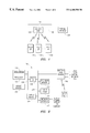
- FIG. 1 is a block diagram depicting a telephony arrangement having a wireless hub arrangement that is arranged to provide telephony functions, in accordance with certain embodiments of the present invention
- FIG. 2 is a block diagram depicting an exemplary wireless hub arrangement, as in FIG. 1, having a computer system configured to run a telephony application, a base station device, and at least one user device, in accordance with certain embodiments of the present invention
- FIG. 3 is a functional block diagram depicting a telephony application, as in FIG. 2, having a user interface that includes a graphical user interface (GUI), an automatic speech recognition (ASR) engine and a text-to-speech (TTS) engine, and a dynamic allocation map, in accordance with certain embodiments of the present invention;
- GUI graphical user interface
- ASR automatic speech recognition
- TTS text-to-speech
- FIG. 4 graphically depicts a dynamic allocation map, as in FIG. 3, defining a user identifier, user characteristics and resources, such as , an access device, in accordance with certain embodiments of the present invention
- FIG. 5 is a flow-chart depicting an exemplary dynamic allocation mapping process, in accordance with certain embodiments of the present invention.
- FIG. 6 is a flow-chart depicting an exemplary calling process, in accordance with certain further embodiments of the present invention.
- FIG. 1 is a block diagram depicting a computer telephony system 100 that is arranged to provide voice and/or data communications to a plurality of local users.
- computer telephony system 100 includes a hub 102 that is arranged to provide telephony functions to a plurality of users through devices 104 a-n.
- hub 102 is depicted as providing wireless communications to a plurality of users, through devices 104 a-n.
- hub 102 can also be arranged to support wired communications to other devices.
- hub 102 is connected to at least one external network 106 through one or more wire or fiber lines 108 .
- lines 108 can also include wireless connections.
- computer telephony system 100 is configured to provide telephony services through one or more telecommunications networks.
- Hub 102 therefore, provides the signal interfacing, switching, monitoring, and controlling functions as required to support the various telephony services, features and operations.
- external network 106 can be any type of communications network that is arranged to provide communications with remote users and/or devices, such as, a public switched telephone network (PTSN). Additionally, external network 106 in certain further embodiments includes or otherwise provides an interface to other external network resources such as an intranet and/or the Internet.
- PTSN public switched telephone network
- Devices 104 a-n can include any type of communication device that is configured for accessing a computer telephony system.
- device 104 a can be a wireless telephone or pager type of device
- device 104 b can be a modem-configured computing device such as a portable computer or personal digital assistant type of device.
- Devices 104 a-n are typically configured to transmit and receive (i.e., exchange) information in the form of either analog or digital data through hub 104 , lines 108 and the various resources provided by external network 106 .
- FIG. 2 is a block diagram depicting an exemplary hub 102 that is based primarily on a computer architecture, such as, for example, that found in a contemporary personal computer (PC) or like computer system.
- hub 102 includes a conventional PC that is connected to a base station 216 and configured to run one or more telephony applications, including, for example, a telephony application that supports dial by name services.
- processor 200 within hub 102 there is at least one processor 200 that is connected to a primary memory 202 through a first bus 204 .
- Processor 200 can be a microprocessor, such as a Pentium II microprocessor available from Intel Corporation of Santa Clara, Calif.
- Processor 200 is configured to access primary memory 202 through first bus 204 .
- Primary memory 202 includes random access memory (RAM), such as, dynamic random access memory (DRAM), which is configured to store data associated with at least one telephony application 218 that runs in processor 200 .
- RAM random access memory
- DRAM dynamic random access memory
- first bus 204 is further interfaced to a second bus 208 , through a bus interface (I/F) 206 .
- second bus 208 can be a Universal Serial Bus (USB), a Peripheral Component Interconnect (PCI) bus, an Industry Standard Architecture(ISA)bus, or other similar bus.
- USB Universal Serial Bus
- PCI Peripheral Component Interconnect
- ISA Industry Standard Architecture
- a plurality of devices can be connected to second bus 208 .
- a secondary memory 210 can be connected to second bus 208 to provide additional data storage.
- Secondary memory 210 can include, for example, additional RAM, DRAM, static random access memory (SRAM) (e.g., flash memory), a disk or tape drive and associated magnetic or optomagnetic storage medium, an optical storage drive and optical storage medium, or other like storage device.
- SRAM static random access memory
- At least one input device 212 is also connected to second bus 208 and configured to accept inputs from an operator.
- Input device 212 can include, for example, a keyboard device, a mouse device, a trackball device, a pen device, a pointing device, a touch sensitive input device, a microphone device, or other like input device. The inputs from input device 212 are then provided to processor 200 , application 218 , or any of the other applicable connected devices in FIGS. 1 and 2.
- At least one output device 214 is also connected to second bus 208 .
- Output device 214 is configured to generate an output suitable for use by a user (with or without additional devices) in response to one or more signals from processor 200 .
- output device 214 can include a cathode-ray tube (CRT) generated display, flat panel display, a printer, an audio monitor, or other like devices.
- output device 214 includes a display device such as a CRT or flat panel display.
- Hub 102 also includes a base station 216 that is configured to support telephony operations within computer telephony system 100 . As shown, base station 216 is connected to second bus 208 . Base station 216 includes, for example, a switch matrix and associated processing and/or interface circuitry (not shown). In a wireless hub arrangement 100 , such as that depicted in FIG. 1, control device 216 also includes transceiver circuitry that supports the wireless communications to/from devices 104 a-n. Base station 216 also provides an interface to lines 108 .
- Base station 216 is configured to exchange information and to respond to one or more commands from application 218 to selectively control the switch matrix as required to support various telephony operations. To accomplish this, base station 216 is configured to provide status information about the telephony operations, e.g., information about a call, and status information about or from the various devices 104 a-n.
- status information about the telephony operations e.g., information about a call, and status information about or from the various devices 104 a-n.
- An optional network interface device 220 is also connected to second bus 208 to provide additional telephony communications, such as, voice over Internet Protocol (VOIP), and/or non-telephony communications between processor 200 , for example, a local area network (LAN) (not shown).
- VOIP voice over Internet Protocol
- LAN local area network
- second bus 208 is depicted as connecting several different devices to first bus 204 and processor 200 , it is to be understood that this is only an exemplary configuration, and that certain additional embodiments in accordance with the present invention use a plurality of buses, direct interfaces, and/or shared interfaces between the various devices.
- hub 102 can be connected to or otherwise provided in hub 102 as needed to support wired or wireless communications and/or other networking capabilities.
- FIG. 3 depicts relevant portions of an exemplary telephony application 218 that is configured to operate substantially within processor 200 .
- Application 218 is configured with a dynamic allocation map 300 , which is accessible through a user interface 302 .
- User interface 302 includes an automatic voice recognition (ASR) engine 304 , a text-to-speech (TTS) engine 306 and a graphical user interface (GUI) 308 .
- ASR 304 is configured to receive user inputs, for example, voice or keypad inputs from devices 104 or line 106 (via base sation 216 , etc.). The received voice or keypad inputs are then interpreted (e.g., sampled, analyzed, processed, and/or compared) within user interface 302 and by using dynamic allocation map 300 .
- TTS engine 306 is configured to support the various functions of user interface 302 , for example, by providing text-to-speech outputs via either device 104 and/or output device 214 .
- Dynamic user interface 302 and allocation map 300 are arranged to provide positive control over the user's, resources and calling processes associated with the computer telephony system, while also allowing users the flexibility to selectively access the system in a variety of ways and using a variety of resources (e.g., access devices).
- a user can select an access device ( 104 ) and then simply logs into the system using the selected access device.
- the user logs into the system by voice inputs that are interpreted and processed by user interface 302 , for example, using ASR engine 304 and other logic.
- dynamic allocation map 300 is updated or otherwise revised to identify that the user is accessing the system from a particular access device.
- dynamic allocation map 300 When dynamic allocation map 300 is updated the applicable characteristics associated with the user are temporarily assigned to the particular device. This updating process is fully automated such that, for example, a user need only select an access device ( 104 ) and identify who they are by voice. The updating process then verifies the identification and updates dynamic allocation map 300 , thereby assigning the identified user's characteristics to the device. Subsequent calls to the user will then be routed to the selected device or an associated telephony service as identified for the user in updated dynamic allocation map 300 .
- FIG. 4 depicts a functional block diagram of a portion of an exemplary dynamic allocation map 300 .
- a user identifier 402 that is linked or otherwise logically tied to one or more corresponding user characteristics 404 .
- User characteristics 404 can include telephony features, services, restrictions, limitations, options, class of service, and the like, which are associated with the user.
- the linking of the user identifier 402 (e.g., a named user) with the user characteristics 404 can be established during an initial set-up procedure, for example, from an operator's console or other access device.
- User characteristics 404 can also be established or otherwise modified by either an operator or the user at a later time, again using either an operators console or an access device.
- dynamic allocation map 300 includes resource identifiers 406 that includes access device identifiers 408 .
- access device identifier 408 can include specific connectivity information about the access device, for example, the type of device and the extension or port number of the device. In this manner, subsequent calls to the user identified by user identifier 402 will be routed to access device 408 .
- FIG. 5 is a flow-chart depicting an exemplary dynamic allocation mapping process 500 for use with application 218 , in accordance with certain exemplary embodiments of the present invention.
- step 502 characteristics are defined for each of the users.
- step 504 which can be conducted at the same time as step 502 or prior thereto, the various telephony resources are defined. Once steps 502 and 504 have been completed, then the computer telephony system 100 is ready to support the users telephony needs.
- a user selects an access device from among the various resources defined in step 504 .
- the user logs into the computer telephony system 100 from the selected access device (e.g., 104 a ).
- the user's characteristics, as defined in step 502 are applied to the selected access device.
- Subsequent calls to the user are then directed to the selected access device, as depicted in step 512 .
- FIG. 6 is a flow-chart depicting an exemplary calling process 600 for use with application 218 , in accordance with certain exemplary embodiments of the present invention.
- the calling party connects to computer telephony system 100 .
- the calling party identifies, for example, by stating the user's name, the user being called.
- the identity of the called party is then determined, for example, by interpreting the voice input from the calling party from step 604 .
- the call is then directed to the selected access device or other telephony service (e.g., voice mail) for the called party.
- the selected access device or other telephony service e.g., voice mail
Abstract
Description
Claims (24)
Priority Applications (3)
| Application Number | Priority Date | Filing Date | Title |
|---|---|---|---|
| US09/160,371 US6480580B1 (en) | 1998-09-24 | 1998-09-24 | User addressable computer telephony system |
| AU61522/99A AU6152299A (en) | 1998-09-24 | 1999-09-16 | Computer telephony system providing personal communication service |
| PCT/US1999/021568 WO2000018093A1 (en) | 1998-09-24 | 1999-09-16 | Computer telephony system providing personal communication service |
Applications Claiming Priority (1)
| Application Number | Priority Date | Filing Date | Title |
|---|---|---|---|
| US09/160,371 US6480580B1 (en) | 1998-09-24 | 1998-09-24 | User addressable computer telephony system |
Publications (1)
| Publication Number | Publication Date |
|---|---|
| US6480580B1 true US6480580B1 (en) | 2002-11-12 |
Family
ID=22576607
Family Applications (1)
| Application Number | Title | Priority Date | Filing Date |
|---|---|---|---|
| US09/160,371 Expired - Lifetime US6480580B1 (en) | 1998-09-24 | 1998-09-24 | User addressable computer telephony system |
Country Status (3)
| Country | Link |
|---|---|
| US (1) | US6480580B1 (en) |
| AU (1) | AU6152299A (en) |
| WO (1) | WO2000018093A1 (en) |
Cited By (7)
| Publication number | Priority date | Publication date | Assignee | Title |
|---|---|---|---|---|
| US6735287B2 (en) * | 2001-11-16 | 2004-05-11 | Sbc Technology Resources, Inc. | Method and system for multimodal presence detection |
| US20050054338A1 (en) * | 2003-09-10 | 2005-03-10 | Nec Corporation | Mobile communication system |
| US7072939B1 (en) * | 2000-01-27 | 2006-07-04 | International Business Machines Corporation | Instant selective multiple soft document sharing between multiple heterogeneous computing devices |
| US20070077914A1 (en) * | 2005-08-26 | 2007-04-05 | Trevor Plestid Thomas L | Data session authentication credentials update for a wireless communication device |
| US20070123251A1 (en) * | 1996-10-23 | 2007-05-31 | Riparius Ventures, Llc | Remote internet telephony device |
| US7415502B2 (en) | 2001-11-16 | 2008-08-19 | Sbc Technology Resources, Inc. | Method and system for intelligent routing based on presence detection |
| US20100115084A1 (en) * | 2008-11-05 | 2010-05-06 | Siemens Communications, Inc. a corporation of the State of Delware | Power management for a communications system |
Families Citing this family (4)
| Publication number | Priority date | Publication date | Assignee | Title |
|---|---|---|---|---|
| US8098806B2 (en) * | 2001-09-05 | 2012-01-17 | Vocera Communications, Inc. | Non-user-specific wireless communication system and method |
| US7953447B2 (en) | 2001-09-05 | 2011-05-31 | Vocera Communications, Inc. | Voice-controlled communications system and method using a badge application |
| US6892083B2 (en) | 2001-09-05 | 2005-05-10 | Vocera Communications Inc. | Voice-controlled wireless communications system and method |
| EP2130202A4 (en) * | 2007-02-22 | 2010-04-14 | Vocera Communications Inc | Voice-controlled communications system and method having an access device or badge application |
Citations (17)
| Publication number | Priority date | Publication date | Assignee | Title |
|---|---|---|---|---|
| US5206901A (en) * | 1991-12-23 | 1993-04-27 | At&T Bell Laboratories | Method and apparatus for alerting multiple telephones for an incoming call |
| US5325421A (en) * | 1992-08-24 | 1994-06-28 | At&T Bell Laboratories | Voice directed communications system platform |
| US5327486A (en) * | 1993-03-22 | 1994-07-05 | Bell Communications Research, Inc. | Method and system for managing telecommunications such as telephone calls |
| US5509062A (en) * | 1994-08-03 | 1996-04-16 | At&T Corp. | Intelligent terminal based selective call forwarding |
| EP0719059A2 (en) | 1994-12-23 | 1996-06-26 | AT&T Corp. | Personal communication using intelligent terminals |
| US5572643A (en) * | 1995-10-19 | 1996-11-05 | Judson; David H. | Web browser with dynamic display of information objects during linking |
| US5590178A (en) * | 1993-09-28 | 1996-12-31 | Fujitsu Limited | Electronic mail system linked with telephone |
| US5652789A (en) * | 1994-09-30 | 1997-07-29 | Wildfire Communications, Inc. | Network based knowledgeable assistant |
| US5719921A (en) * | 1996-02-29 | 1998-02-17 | Nynex Science & Technology | Methods and apparatus for activating telephone services in response to speech |
| US5862207A (en) | 1995-03-06 | 1999-01-19 | Toshiba Corporation | Method and system for providing virtual telephone terminals |
| US5884262A (en) * | 1996-03-28 | 1999-03-16 | Bell Atlantic Network Services, Inc. | Computer network audio access and conversion system |
| US5946386A (en) * | 1996-03-11 | 1999-08-31 | Xantel Corporation | Call management system with call control from user workstation computers |
| US5953392A (en) * | 1996-03-01 | 1999-09-14 | Netphonic Communications, Inc. | Method and apparatus for telephonically accessing and navigating the internet |
| US5958014A (en) * | 1996-09-24 | 1999-09-28 | Intervoice Limited Partnership | System and method for establishing a real-time agent pool between computer systems |
| US6058366A (en) * | 1998-02-25 | 2000-05-02 | Lernout & Hauspie Speech Products N.V. | Generic run-time engine for interfacing between applications and speech engines |
| US6064730A (en) * | 1996-06-18 | 2000-05-16 | Lucent Technologies Inc. | Customer-self routing call center |
| US6144938A (en) * | 1998-05-01 | 2000-11-07 | Sun Microsystems, Inc. | Voice user interface with personality |
-
1998
- 1998-09-24 US US09/160,371 patent/US6480580B1/en not_active Expired - Lifetime
-
1999
- 1999-09-16 AU AU61522/99A patent/AU6152299A/en not_active Abandoned
- 1999-09-16 WO PCT/US1999/021568 patent/WO2000018093A1/en active Application Filing
Patent Citations (18)
| Publication number | Priority date | Publication date | Assignee | Title |
|---|---|---|---|---|
| US5206901A (en) * | 1991-12-23 | 1993-04-27 | At&T Bell Laboratories | Method and apparatus for alerting multiple telephones for an incoming call |
| US5325421A (en) * | 1992-08-24 | 1994-06-28 | At&T Bell Laboratories | Voice directed communications system platform |
| US5327486A (en) * | 1993-03-22 | 1994-07-05 | Bell Communications Research, Inc. | Method and system for managing telecommunications such as telephone calls |
| US5590178A (en) * | 1993-09-28 | 1996-12-31 | Fujitsu Limited | Electronic mail system linked with telephone |
| US5509062A (en) * | 1994-08-03 | 1996-04-16 | At&T Corp. | Intelligent terminal based selective call forwarding |
| US5652789A (en) * | 1994-09-30 | 1997-07-29 | Wildfire Communications, Inc. | Network based knowledgeable assistant |
| EP0719059A2 (en) | 1994-12-23 | 1996-06-26 | AT&T Corp. | Personal communication using intelligent terminals |
| US5550907A (en) * | 1994-12-23 | 1996-08-27 | Lucent Technologies Inc. | Personal communication using intelligent terminals |
| US5862207A (en) | 1995-03-06 | 1999-01-19 | Toshiba Corporation | Method and system for providing virtual telephone terminals |
| US5572643A (en) * | 1995-10-19 | 1996-11-05 | Judson; David H. | Web browser with dynamic display of information objects during linking |
| US5719921A (en) * | 1996-02-29 | 1998-02-17 | Nynex Science & Technology | Methods and apparatus for activating telephone services in response to speech |
| US5953392A (en) * | 1996-03-01 | 1999-09-14 | Netphonic Communications, Inc. | Method and apparatus for telephonically accessing and navigating the internet |
| US5946386A (en) * | 1996-03-11 | 1999-08-31 | Xantel Corporation | Call management system with call control from user workstation computers |
| US5884262A (en) * | 1996-03-28 | 1999-03-16 | Bell Atlantic Network Services, Inc. | Computer network audio access and conversion system |
| US6064730A (en) * | 1996-06-18 | 2000-05-16 | Lucent Technologies Inc. | Customer-self routing call center |
| US5958014A (en) * | 1996-09-24 | 1999-09-28 | Intervoice Limited Partnership | System and method for establishing a real-time agent pool between computer systems |
| US6058366A (en) * | 1998-02-25 | 2000-05-02 | Lernout & Hauspie Speech Products N.V. | Generic run-time engine for interfacing between applications and speech engines |
| US6144938A (en) * | 1998-05-01 | 2000-11-07 | Sun Microsystems, Inc. | Voice user interface with personality |
Non-Patent Citations (2)
| Title |
|---|
| Regnier et al, "Personal Communication Services-The New POTS", Proceedings of The Global Telecommunications Conference and Exhibition (Globecom), Us, New York, IEEE, vol. -pp. 420-426. |
| Regnier et al, "Personal Communication Services—The New POTS", Proceedings of The Global Telecommunications Conference and Exhibition (Globecom), Us, New York, IEEE, vol. —pp. 420-426. |
Cited By (20)
| Publication number | Priority date | Publication date | Assignee | Title |
|---|---|---|---|---|
| US20070123251A1 (en) * | 1996-10-23 | 2007-05-31 | Riparius Ventures, Llc | Remote internet telephony device |
| US7072939B1 (en) * | 2000-01-27 | 2006-07-04 | International Business Machines Corporation | Instant selective multiple soft document sharing between multiple heterogeneous computing devices |
| US7065184B2 (en) | 2001-11-16 | 2006-06-20 | Sbc Technology Resources, Inc. | Method and system for multimodal presence detection |
| US7949105B2 (en) | 2001-11-16 | 2011-05-24 | At&T Intellectual Property I, L.P. | Method and system for multimodal presence detection |
| US20060203973A1 (en) * | 2001-11-16 | 2006-09-14 | Vishik Claire Svetlana | Method and system for multimodal presence detection |
| US6735287B2 (en) * | 2001-11-16 | 2004-05-11 | Sbc Technology Resources, Inc. | Method and system for multimodal presence detection |
| US7415502B2 (en) | 2001-11-16 | 2008-08-19 | Sbc Technology Resources, Inc. | Method and system for intelligent routing based on presence detection |
| US20090019542A1 (en) * | 2001-11-16 | 2009-01-15 | Claire Svetlana Vishik | Method and system for intelligent rounting based on presence detection |
| US7630478B2 (en) | 2001-11-16 | 2009-12-08 | Sbc Technology Resources, Inc. | Method and system for multimodal presence detection |
| US8095605B2 (en) | 2001-11-16 | 2012-01-10 | At&T Intellectual Property I, Lp | Method and system for intelligent routing based on presence detection |
| US20100041374A1 (en) * | 2001-11-16 | 2010-02-18 | Claire Svetlana Vishik | Method and system for multimodal presence detection |
| US20050054338A1 (en) * | 2003-09-10 | 2005-03-10 | Nec Corporation | Mobile communication system |
| US7610054B2 (en) * | 2003-10-09 | 2009-10-27 | Nec Corporation | Mobile communication system |
| US20070077914A1 (en) * | 2005-08-26 | 2007-04-05 | Trevor Plestid Thomas L | Data session authentication credentials update for a wireless communication device |
| US20110165863A1 (en) * | 2005-08-26 | 2011-07-07 | Research In Motion Limited | Data Seesion Authentication Credentials Update For A Wireless Communication Device |
| US7634253B2 (en) * | 2005-08-26 | 2009-12-15 | Research In Motion Limited | Data session authentication credentials update for a wireless communication device |
| US8107928B2 (en) | 2005-08-26 | 2012-01-31 | Research In Motion Limited | Data session authentication credentials update for a wireless communication device |
| US8532621B2 (en) | 2005-08-26 | 2013-09-10 | Blackberry Limited | Data session authentication credentials update for a wireless communication device |
| US20100115084A1 (en) * | 2008-11-05 | 2010-05-06 | Siemens Communications, Inc. a corporation of the State of Delware | Power management for a communications system |
| US8645507B2 (en) * | 2008-11-05 | 2014-02-04 | Siemens Enterprise Communications, Inc. | Power management for a communications system |
Also Published As
| Publication number | Publication date |
|---|---|
| WO2000018093A1 (en) | 2000-03-30 |
| AU6152299A (en) | 2000-04-10 |
Similar Documents
| Publication | Publication Date | Title |
|---|---|---|
| US7933394B2 (en) | Method and apparatus for routing calls based on the identification of the calling party or calling line | |
| US5930700A (en) | System and method for automatically screening and directing incoming calls | |
| JP4362178B2 (en) | Wireless communication apparatus having API between user application program and telephone program and method thereof | |
| US7983661B2 (en) | Method and means for controlling the availability of mobile agents in a call centre environment | |
| US6011843A (en) | Method and apparatus for initiating parallel connections to identified plural sites | |
| US10936151B2 (en) | System and method for voice activated provisioning of telecommunication services | |
| CA2495093A1 (en) | Providing routing information in a communication system | |
| US7149297B2 (en) | Networkwide desk sharing with automatic device relocation | |
| US6480580B1 (en) | User addressable computer telephony system | |
| US7110516B2 (en) | Dynamic telephone configuration | |
| CN101119413B (en) | Internet telephone system, call connection controller, terminal association method used therein and its program | |
| US7965831B2 (en) | Telephone control device, telephone control method, telephone control program, telephone terminal, telephone calling method, telephone calling program and telephone control system | |
| KR20210060906A (en) | Method And Apparatus for Direct Contacting Available Person in Charge | |
| US6856617B2 (en) | Method for processing outgoing call in voice over internet protocol (VIP) gateway | |
| JP2847039B2 (en) | Incoming call notification system and information processing system used therefor | |
| Cisco | Preparing the Cisco CallManager and Octel Systems | |
| Cisco | Preparing the Cisco CallManager and Octel Systems | |
| US20040053616A1 (en) | Method and apparatus for multiple terminal equipment routing | |
| WO2001039478A1 (en) | Method and system for transmitting communication signals through internet and a public switched telephone network | |
| EP3745694A1 (en) | Method and telecommunication system for establishing a call via at least one telecommunication network using multiple call numbers | |
| US20070250579A1 (en) | Method and apparatus for presence indication of cellular telephones | |
| KR20000072754A (en) | Method and system for transmitting communication signals through the internet and a public switched telephone network | |
| US20060246926A1 (en) | Method and apparatus for combining enterprise IP-PBX and cellular mobile services | |
| US7415103B2 (en) | Method and configuration for controlling and/or monitoring a terminal connected to a communications system | |
| US5828741A (en) | System and method for providing a multi-number plan for use with a general telephone and a key telephone in a key telephone system |
Legal Events
| Date | Code | Title | Description |
|---|---|---|---|
| AS | Assignment |
Owner name: ERICSSON INC., NORTH CAROLINA Free format text: ASSIGNMENT OF ASSIGNORS INTEREST;ASSIGNORS:BESWICK, ANTHONY PAUL;PERSSON, MATS;REEL/FRAME:009945/0521 Effective date: 19990401 Owner name: ERICSSON, INC., NORTH CAROLINA Free format text: ASSIGNMENT OF ASSIGNORS INTEREST;ASSIGNORS:BESWICK, ANTONY PAUL;UYENO, SHELLEY LAM;REEL/FRAME:009946/0339 Effective date: 19990401 |
|
| AS | Assignment |
Owner name: ERICSSON INC., NORTH CAROLINA Free format text: ASSIGNMENT OF ASSIGNORS INTEREST;ASSIGNORS:BESWICK, ANTONY PAUL;PERSSON, MATS;REEL/FRAME:010214/0631 Effective date: 19990401 |
|
| AS | Assignment |
Owner name: ERICSSON BUSINESS NETWORKS AB, SWEDEN Free format text: ASSIGNMENT OF ASSIGNORS INTEREST;ASSIGNOR:ERICSSON INC.;REEL/FRAME:010327/0046 Effective date: 19991021 |
|
| STCF | Information on status: patent grant |
Free format text: PATENTED CASE |
|
| FPAY | Fee payment |
Year of fee payment: 4 |
|
| FPAY | Fee payment |
Year of fee payment: 8 |
|
| FPAY | Fee payment |
Year of fee payment: 12 |