US6435708B1 - Safety protective cover of a blender - Google Patents
Safety protective cover of a blender Download PDFInfo
- Publication number
- US6435708B1 US6435708B1 US10/072,920 US7292002A US6435708B1 US 6435708 B1 US6435708 B1 US 6435708B1 US 7292002 A US7292002 A US 7292002A US 6435708 B1 US6435708 B1 US 6435708B1
- Authority
- US
- United States
- Prior art keywords
- protective cover
- section
- blender
- blending container
- latch
- Prior art date
- Legal status (The legal status is an assumption and is not a legal conclusion. Google has not performed a legal analysis and makes no representation as to the accuracy of the status listed.)
- Expired - Fee Related
Links
Images


Classifications
-
- A—HUMAN NECESSITIES
- A21—BAKING; EDIBLE DOUGHS
- A21C—MACHINES OR EQUIPMENT FOR MAKING OR PROCESSING DOUGHS; HANDLING BAKED ARTICLES MADE FROM DOUGH
- A21C1/00—Mixing or kneading machines for the preparation of dough
- A21C1/14—Structural elements of mixing or kneading machines; Parts; Accessories
- A21C1/148—Safety arrangements
-
- A—HUMAN NECESSITIES
- A21—BAKING; EDIBLE DOUGHS
- A21C—MACHINES OR EQUIPMENT FOR MAKING OR PROCESSING DOUGHS; HANDLING BAKED ARTICLES MADE FROM DOUGH
- A21C1/00—Mixing or kneading machines for the preparation of dough
- A21C1/02—Mixing or kneading machines for the preparation of dough with vertically-mounted tools; Machines for whipping or beating
-
- B—PERFORMING OPERATIONS; TRANSPORTING
- B01—PHYSICAL OR CHEMICAL PROCESSES OR APPARATUS IN GENERAL
- B01F—MIXING, e.g. DISSOLVING, EMULSIFYING OR DISPERSING
- B01F27/00—Mixers with rotary stirring devices in fixed receptacles; Kneaders
- B01F27/80—Mixers with rotary stirring devices in fixed receptacles; Kneaders with stirrers rotating about a substantially vertical axis
- B01F27/805—Mixers with rotary stirring devices in fixed receptacles; Kneaders with stirrers rotating about a substantially vertical axis wherein the stirrers or the receptacles are moved in order to bring them into operative position; Means for fixing the receptacle
-
- B—PERFORMING OPERATIONS; TRANSPORTING
- B01—PHYSICAL OR CHEMICAL PROCESSES OR APPARATUS IN GENERAL
- B01F—MIXING, e.g. DISSOLVING, EMULSIFYING OR DISPERSING
- B01F35/00—Accessories for mixers; Auxiliary operations or auxiliary devices; Parts or details of general application
- B01F35/45—Closures or doors specially adapted for mixing receptacles; Operating mechanisms therefor
- B01F35/452—Closures or doors specially adapted for mixing receptacles; Operating mechanisms therefor by moving them in the plane of the opening
-
- B—PERFORMING OPERATIONS; TRANSPORTING
- B01—PHYSICAL OR CHEMICAL PROCESSES OR APPARATUS IN GENERAL
- B01F—MIXING, e.g. DISSOLVING, EMULSIFYING OR DISPERSING
- B01F35/00—Accessories for mixers; Auxiliary operations or auxiliary devices; Parts or details of general application
- B01F35/60—Safety arrangements
Definitions
- the present invention is related to a safety protective cover of a blender.
- the protective cover is transparent and integrally molded.
- the protective cover is associated with the blending container to achieve a protection effect.
- FIG. 9 shows a conventional food blender used to blend flour mash, etc.
- the food blender includes a bed 7 having a forward extending substantially semicircular support arm 71 .
- a blending container 8 is placed on the support arm 71 .
- the head section 72 of the blender, which is disposed on upper side of the bed 7 has a rotary shaft 73 right above the blending container.
- a blending bar 74 is mounted on the rotary shaft for stirring and blending the materials contained in the blending container.
- a protective mesh 9 is mounted on the head section to solve this problem.
- the protective mesh 9 is conic and positioned around the rotary shaft.
- the protective mesh shields the upper side of the blending container to prevent a user from incautiously touching the blending bar in operation.
- the protective mesh cannot avoid splash of the materials.
- the protective mesh will be contaminated by the remainders which are hard to be cleared up. Under such circumstance, the user must detach the protective mesh for washing. This is quite inconvenient to a user so that the user often simply wipes the protective mesh without taking off the same. As a result, much dirt will accumulate in the meshes of the protective mesh.
- the protective mesh can provide a protection function.
- the protective mesh cannot shield the blending container.
- the blender should be in an off state when the container is descended.
- the user's hand extends into the blending container and the blender is mis-activated, the user may still get hurt.
- the protective cover is associated with the blending container and can be easily detached therefrom. Only after the blending container is ascended and located, the blender is activated so that the safety in use can be ensured.
- the protective cover serves to prevent the blended materials from splashing out.
- FIG. 1 is a perspective assembled view of the present invention, showing that the protective cover is mounted on the blender;
- FIG. 2 is a perspective view of the protective cover of the present invention
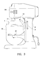
- FIG. 3 is a side view showing that the protective cover of the present invention is mounted on the blender;
- FIG. 4 is a side view according to FIG. 3, showing that the blending container is ascended;
- FIG. 5 shows that the protective cover of the present invention is assembled with or disassembled from the blending container
- FIG. 6 shows that a user presses the latch member of the protective cover of the present invention
- FIG. 7 is a sectional view taken along line 7 — 7 of FIG. 6;
- FIG. 8 shows that the protective cover of the present invention is latched with the blending container
- FIG. 9 is a perspective view of a conventional blender.
- the blender of the present invention includes a bed 10 and a support arm 11 extending from front side of the bed 10 .
- a crank 14 is disposed on a lateral side of the bed for moving the support arm up and down.
- a U-shaped blending container 20 can be placed on the support arm 11 .
- the top edge of the blending container is formed with a flange 21 .
- a head section 101 of the blender is disposed on upper side of the bed 10 .
- the head section 101 has a rotary shaft 12 right above the blending container.
- a blending device 5 is mounted on the rotary shaft 12 .
- a protective cover 4 is connected with upper edge of the blending container 20 .
- the protective cover is integrally made of a transparent material.
- the bottom of the protective cover at least covers the upper opening 201 of blending container.
- the bottom side of the circumference of the protective cover abuts against the top side of the flange 21 of the blending container.
- An annular section 41 protrudes from the bottom of the protective cover and extends along the inner face of the wall of the blending container.
- Two handle sections 42 transversely protrude from two lateral sides of the bottom of the protective cover.
- a latch member 3 is disposed under the bottom side of each handle section 42 . The latch members 3 are latched with lower side of the flange of the blending container to firmly associate the protective cover with the blending container as shown in FIGS. 6 and 8.
- the latch member has a fixing section 31 including two symmetrical lugs 311 . Each lug has a fixing hole 312 . Two projecting posts 421 are disposed in the handle section corresponding to the lugs for a screw 422 to lock the latch member.
- the latch member has a plate-shaped latch hook 32 downward extending between the two lugs.
- the latch hook is bent toward the center of the protective cover to form a stop section 321 for stopping lower side of the flange of the blending container.
- the stop section is further reversely bent and extended to form a press section 322 for a user to press.
- the circumference of the protective cover is formed with a notch 44 .
- the top side of the flange of the blending container is formed with a projecting section 211 .
- the projecting section 211 can be engaged in the notch 44 to locate the protective cover.
- the top of the protective cover is formed with an opening 45 at the axis of the rotary shaft 12 .
- the opening 45 linearly extends to the circumference of the protective cover to form a split 451 .
- the width of the opening is at least equal to the diameter of the rotary shaft.
- a through hole 46 is formed on the protective cover, whereby a user can add water through the through hole into the blending container.
- a touch board 47 projects from the protective cover.
- a switch 13 is disposed on lower side of the head section 101 above the touch board. When the blending container is ascended, referring to FIG. 4, the touch board touches the switch to turn on the blender.
- the blender container is placed on the support arm.
- the protective cover is overlaid on the blending container with the shaft of the blending device passing through the split 451 of the protective cover.
- a user respectively presses the press sections 322 of the two latch members with two hands.
- the two lugs of the fixing sections of the latch members are locked and the latch hooks 32 are entirely flexed and deformed to downward turn open the stop sections 321 .
- the protective cover is firmly associated with the blending container.
- the protective cover is located with the opening aligned with lower side of the head section.
- the top side of the protective cover shields the gap between the upper side of the blending container and the head section and touches the switch 13 . Therefore, the blending container is ensured to locate in a ready position and in a safe state and then the blender is activated.
- the protective cover By means of the protective cover, the blended materials are obstructed from splashing out. The use can directly see the blending state through the protective cover.
- the protective cover is simply associated with the blending container by means of hooking the latch members with the flange. Therefore, after the blending operation is finished and it is desired to take off the protective cover for washing, the user only needs to bias the latch members on two sides of the protective cover with two hands to directly taking off the protective cover from the blending container. Accordingly, no other component needs to be detached and it is convenient to take off and wash the protective cover.
- the protective cover serves to protect a user from incautiously touching the blending bar and getting hurt. Moreover, the manufacturing cost of the protective cover is lower than the conventional protective mesh and the appearance of the protective cover is more beautiful than the protective mesh.
Abstract
A safety protective cover of a blender. The protective cover is associated with upper edge of a blending container. The bottom of the protective cover at least covers an upper opening of the blending container. The top side of the protective cover is formed with an opening at an axis of the rotary shaft. The opening linearly extends to a circumference of the protective cover to form a split. A water filling hole is formed on the protective cover. At least one latch section is disposed on the bottom of the protective cover for latching the protective cover with upper edge of the blending container.
Description
The present invention is related to a safety protective cover of a blender. The protective cover is transparent and integrally molded. The protective cover is associated with the blending container to achieve a protection effect.
FIG. 9 shows a conventional food blender used to blend flour mash, etc. The food blender includes a bed 7 having a forward extending substantially semicircular support arm 71. A blending container 8 is placed on the support arm 71. The head section 72 of the blender, which is disposed on upper side of the bed 7 has a rotary shaft 73 right above the blending container. A blending bar 74 is mounted on the rotary shaft for stirring and blending the materials contained in the blending container.
In blending operation, the materials often splash to contaminate the blender and the environment. Moreover, the blender is rotated at very high rotational speed and great torque. This is dangerous to a user.
A protective mesh 9 is mounted on the head section to solve this problem. The protective mesh 9 is conic and positioned around the rotary shaft. When the blending container ascends to make the blending bar extend into the blending container, the protective mesh shields the upper side of the blending container to prevent a user from incautiously touching the blending bar in operation. However, such protective mesh cannot avoid splash of the materials. On the contrary, the protective mesh will be contaminated by the remainders which are hard to be cleared up. Under such circumstance, the user must detach the protective mesh for washing. This is quite inconvenient to a user so that the user often simply wipes the protective mesh without taking off the same. As a result, much dirt will accumulate in the meshes of the protective mesh. It is known that a certain amount of water is often added into the materials to modulate the thickness of the blended materials. A user often directly adds the water through the protective mesh into the blending container during operation. Under such circumstance, the water will entrain the dirt in the protective mesh to contaminate the blended materials.
Furthermore, only when the blending container ascends, the protective mesh can provide a protection function. When the blending container is descended, the protective mesh cannot shield the blending container. Normally the blender should be in an off state when the container is descended. However, when the user's hand extends into the blending container and the blender is mis-activated, the user may still get hurt.
It is therefore a primary object of the present invention to provide a safety protective cover of a blender. The protective cover is associated with the blending container and can be easily detached therefrom. Only after the blending container is ascended and located, the blender is activated so that the safety in use can be ensured.
It is a further object of the present invention to provide the above safety protective cover which is made by integral molding to lower manufacturing cost. In addition, the protective cover serves to prevent the blended materials from splashing out.
The present invention can be best understood through the following description and accompanying drawings wherein:
FIG. 1 is a perspective assembled view of the present invention, showing that the protective cover is mounted on the blender;
FIG. 2 is a perspective view of the protective cover of the present invention;
FIG. 3 is a side view showing that the protective cover of the present invention is mounted on the blender;
FIG. 4 is a side view according to FIG. 3, showing that the blending container is ascended;
FIG. 5 shows that the protective cover of the present invention is assembled with or disassembled from the blending container;
FIG. 6 shows that a user presses the latch member of the protective cover of the present invention;
FIG. 7 is a sectional view taken along line 7—7 of FIG. 6;
FIG. 8 shows that the protective cover of the present invention is latched with the blending container; and
FIG. 9 is a perspective view of a conventional blender.
Please refer to FIGS. 1 to 8. The blender of the present invention includes a bed 10 and a support arm 11 extending from front side of the bed 10. A crank 14 is disposed on a lateral side of the bed for moving the support arm up and down. A U-shaped blending container 20 can be placed on the support arm 11. The top edge of the blending container is formed with a flange 21. A head section 101 of the blender is disposed on upper side of the bed 10. The head section 101 has a rotary shaft 12 right above the blending container. A blending device 5 is mounted on the rotary shaft 12.
A protective cover 4 is connected with upper edge of the blending container 20. Referring to FIG. 2, the protective cover is integrally made of a transparent material. The bottom of the protective cover at least covers the upper opening 201 of blending container. The bottom side of the circumference of the protective cover abuts against the top side of the flange 21 of the blending container. An annular section 41 protrudes from the bottom of the protective cover and extends along the inner face of the wall of the blending container. Two handle sections 42 transversely protrude from two lateral sides of the bottom of the protective cover. A latch member 3 is disposed under the bottom side of each handle section 42. The latch members 3 are latched with lower side of the flange of the blending container to firmly associate the protective cover with the blending container as shown in FIGS. 6 and 8.
The latch member has a fixing section 31 including two symmetrical lugs 311. Each lug has a fixing hole 312. Two projecting posts 421 are disposed in the handle section corresponding to the lugs for a screw 422 to lock the latch member.
The latch member has a plate-shaped latch hook 32 downward extending between the two lugs. The latch hook is bent toward the center of the protective cover to form a stop section 321 for stopping lower side of the flange of the blending container. The stop section is further reversely bent and extended to form a press section 322 for a user to press.
As shown in FIG. 5, the circumference of the protective cover is formed with a notch 44. The top side of the flange of the blending container is formed with a projecting section 211. The projecting section 211 can be engaged in the notch 44 to locate the protective cover.
The top of the protective cover is formed with an opening 45 at the axis of the rotary shaft 12. The opening 45 linearly extends to the circumference of the protective cover to form a split 451. The width of the opening is at least equal to the diameter of the rotary shaft.
In addition, a through hole 46 is formed on the protective cover, whereby a user can add water through the through hole into the blending container. Moreover, a touch board 47 projects from the protective cover. A switch 13 is disposed on lower side of the head section 101 above the touch board. When the blending container is ascended, referring to FIG. 4, the touch board touches the switch to turn on the blender.
In use, the blender container is placed on the support arm. The protective cover is overlaid on the blending container with the shaft of the blending device passing through the split 451 of the protective cover. Referring to FIGS. 5 to 8, a user respectively presses the press sections 322 of the two latch members with two hands. At this time, the two lugs of the fixing sections of the latch members are locked and the latch hooks 32 are entirely flexed and deformed to downward turn open the stop sections 321. Under such circumstance, when the user releases the press sections of the latch members, the two latch members will resiliently restore to make the stop sections abut against the flange of the blending container. Accordingly, the protective cover is firmly associated with the blending container. By means of engaging the projecting section in the notch of the protective cover, the protective cover is located with the opening aligned with lower side of the head section.
Referring to FIGS. 3 and 4, when a user cranks the crank 14 to lift the support arm, the top side of the protective cover shields the gap between the upper side of the blending container and the head section and touches the switch 13. Therefore, the blending container is ensured to locate in a ready position and in a safe state and then the blender is activated. By means of the protective cover, the blended materials are obstructed from splashing out. The use can directly see the blending state through the protective cover.
The protective cover is simply associated with the blending container by means of hooking the latch members with the flange. Therefore, after the blending operation is finished and it is desired to take off the protective cover for washing, the user only needs to bias the latch members on two sides of the protective cover with two hands to directly taking off the protective cover from the blending container. Accordingly, no other component needs to be detached and it is convenient to take off and wash the protective cover. The protective cover serves to protect a user from incautiously touching the blending bar and getting hurt. Moreover, the manufacturing cost of the protective cover is lower than the conventional protective mesh and the appearance of the protective cover is more beautiful than the protective mesh.
When the support arm is descended, the switch is free from the touch of the touch board. At this time, the blender is turned off and will not be unexpectedly activated due to incaution. All the blending operation is performed only when the protective cover is mounted and the blending container is truly located. Therefore, the safety of the user can be ensured.
The above embodiment is only used to illustrate the present invention, not intended to limit the scope thereof. Many modifications of the above embodiment can be made without departing from the spirit of the present invention.
Claims (7)
1. A safety protective cover of a blender, the blender having a bed and a support arm extending from front side of the bed for a blending container to rest thereon, the support arm being up and down movable, a head section of the blender being disposed on upper side of the bed, the head section having a rotary shaft right above the blending container, a blending device being mounted on the rotary shaft, said safety protective cover being characterized in that the protective cover is transparent and integrally molded, the protective cover being associated with upper edge of the blending container, a bottom of the protective cover at least covering an upper opening of the blending container, a top side of the protective cover being formed with an opening at an axis of the rotary shaft, the opening linearly extending to a circumference of the protective cover to form a split, the width of the opening being at least equal to the diameter of the rotary shaft, a through hole being formed on the protective cover, at least one latch section being disposed on the bottom of the protective cover for latching with upper edge of the blending container.
2. The safety protective cover of a blender as claimed in claim 1 , wherein a touch board projects from the protective cover and a switch is disposed on lower side of the head section above the touch board.
3. The safety protective cover of a blender as claimed in claim 1 , wherein an annular section protrudes from the bottom of the protective cover and extends along the inner face of the wall of the blending container.
4. The safety protective cover of a blender as claimed in claim 1 , wherein the top edge of the blending container is formed with a flange against which the bottom side of the circumference of the protective cover abuts, the circumference of the protective cover being formed with a notch, the top side of the flange of the blending container being formed with a projecting section, the projecting section being engaged in the notch to locate the protective cover.
5. The safety protective cover of a blender as claimed in claim 1 , wherein at least one handle section transversely protrudes from the bottom of the protective cover, the latch section being disposed on the bottom side of the handle section, whereby the latch section is latched with lower side of the flange of the blending container.
6. The safety protective cover of a blender as claimed in claim 1 or 5 , wherein the latch section is a latch member, the latch member having a fixing section for connecting with the protective cover, the latch member further having a plate-shaped latch hook downward extending from the fixing section, the latch hook being bent toward the center of the protective cover to form a stop section for stopping lower side of the flange of the blending container, the stop section being further reversely bent and extended to form a press section for a user to press.
7. The safety protective cover of a blender as claimed in claim 6 , wherein the fixing section of the latch member includes two symmetrical lugs, each lug having a fixing hole, the latch hook being positioned between the two lugs, two projecting posts being disposed in the handle section of the protective cover corresponding to the lugs for a screw to lock the latch member.
Priority Applications (2)
| Application Number | Priority Date | Filing Date | Title |
|---|---|---|---|
| US10/072,920 US6435708B1 (en) | 2002-02-12 | 2002-02-12 | Safety protective cover of a blender |
| US12/732,097 US9282925B2 (en) | 2002-02-12 | 2010-03-25 | Systems and methods for replacing signal artifacts in a glucose sensor data stream |
Applications Claiming Priority (1)
| Application Number | Priority Date | Filing Date | Title |
|---|---|---|---|
| US10/072,920 US6435708B1 (en) | 2002-02-12 | 2002-02-12 | Safety protective cover of a blender |
Related Parent Applications (1)
| Application Number | Title | Priority Date | Filing Date |
|---|---|---|---|
| US11/077,739 Continuation-In-Part US8858434B2 (en) | 2002-02-12 | 2005-03-10 | Transcutaneous analyte sensor |
Related Child Applications (1)
| Application Number | Title | Priority Date | Filing Date |
|---|---|---|---|
| US10/648,849 Continuation-In-Part US8010174B2 (en) | 2002-02-12 | 2003-08-22 | Systems and methods for replacing signal artifacts in a glucose sensor data stream |
Publications (1)
| Publication Number | Publication Date |
|---|---|
| US6435708B1 true US6435708B1 (en) | 2002-08-20 |
Family
ID=22110554
Family Applications (1)
| Application Number | Title | Priority Date | Filing Date |
|---|---|---|---|
| US10/072,920 Expired - Fee Related US6435708B1 (en) | 2002-02-12 | 2002-02-12 | Safety protective cover of a blender |
Country Status (1)
| Country | Link |
|---|---|
| US (1) | US6435708B1 (en) |
Cited By (31)
| Publication number | Priority date | Publication date | Assignee | Title |
|---|---|---|---|---|
| US20050058018A1 (en) * | 2003-09-16 | 2005-03-17 | Ryan Hooper | Stand mixer |
| US20050258197A1 (en) * | 2004-05-21 | 2005-11-24 | Rukavina Stephen P | Adapter for blender pitcher |
| BE1016274A3 (en) * | 2002-02-21 | 2006-07-04 | Spar Food Machinery Co Ltd | Protective cover for blender, is transparent, integrally molded and connected with blending container |
| US20060227654A1 (en) * | 2005-04-08 | 2006-10-12 | Blackburn Neal H | Mixing machine and associated bowl guard system |
| US20080098905A1 (en) * | 2006-10-31 | 2008-05-01 | Hamilton Beach/Proctor-Silex, Inc. | Blender for Blending Foodstuff |
| US20080271609A1 (en) * | 2007-05-05 | 2008-11-06 | Richard Charles Pahl | Auto-Stir and Tilt Cooking Appliance |
| GB2459309A (en) * | 2008-04-19 | 2009-10-21 | Kenwood Ltd | A Stand Mixer with guarding device |
| WO2012080679A1 (en) | 2010-12-17 | 2012-06-21 | Seb S.A. | Electric household food processor comprising a base supporting a bowl that can be closed with a removable lid |
| US8308344B2 (en) | 2008-01-24 | 2012-11-13 | Premark Feg L.L.C. | Mixing machine with associated bowl guard system |
| CN103229790A (en) * | 2013-04-17 | 2013-08-07 | 宁波肴邦电器有限公司 | Shortener locking mechanism |
| US20130206771A1 (en) * | 2010-09-30 | 2013-08-15 | Vorwerk & Co. Interholding Gmbh | Electrically operated food processor with a cooking vessel, and vessel with a lid |
| WO2016000782A1 (en) * | 2014-07-03 | 2016-01-07 | Aktiebolaget Electrolux | Household appliance mixing arrangement |
| CN105268362A (en) * | 2014-07-22 | 2016-01-27 | 开平市亿洋塑胶制品有限公司 | Anti-overflowing stirring cylinder |
| EP2863783A4 (en) * | 2012-06-26 | 2016-05-11 | Real Foods L L C F | Blender with elevator assembly and removable spindle |
| US9386882B2 (en) | 2012-06-26 | 2016-07-12 | F'real Foods, Llc | Compact blender for frozen beverages |
| US9420917B2 (en) | 2012-06-26 | 2016-08-23 | F'real Foods, Llc | Method for blending food or beverages |
| US9579615B2 (en) | 2012-06-26 | 2017-02-28 | F'real Foods Llc | Blender with elevator assembly and removable spindle |
| CN108720656A (en) * | 2018-06-25 | 2018-11-02 | 杨华根 | A kind of family's noodles served with soy sauce, sesame butter, etc. equipment made based on cold noodles in sauce |
| CN109430315A (en) * | 2018-10-13 | 2019-03-08 | 浙江碟中碟食品有限公司 | Dough mixing machine device for food processing |
| US10342238B2 (en) | 2014-07-03 | 2019-07-09 | Aktiebolaget Electrolux | Household appliance mixing arrangement |
| CN110150344A (en) * | 2019-05-20 | 2019-08-23 | 日照职业技术学院 | A kind of food processing noodle device and with face technique |
| CN110742101A (en) * | 2019-11-22 | 2020-02-04 | 湖南省爱尚乐心食品有限公司 | Dough kneading mixer capable of automatically removing stirring residues |
| USD874222S1 (en) * | 2018-05-22 | 2020-02-04 | Transform Sr Brands Llc | Mixer splash guard |
| CN110865143A (en) * | 2019-11-11 | 2020-03-06 | 山东海普欧环保设备科技有限公司 | Sewage quality detection equipment |
| US11330935B2 (en) * | 2017-02-27 | 2022-05-17 | iYukti LLC | Apparatus and methods for making bread |
| US11545387B2 (en) | 2018-07-13 | 2023-01-03 | Tel Manufacturing And Engineering Of America, Inc. | Magnetic integrated lift pin system for a chemical processing chamber |
| USD984208S1 (en) * | 2020-08-06 | 2023-04-25 | Marc Leclerc | Splash guard |
| USD987372S1 (en) | 2020-06-23 | 2023-05-30 | Whirlpool Corporation | Pouring shield |
| US11730407B2 (en) | 2008-03-28 | 2023-08-22 | Dexcom, Inc. | Polymer membranes for continuous analyte sensors |
| US11883164B2 (en) | 2004-07-13 | 2024-01-30 | Dexcom, Inc. | System and methods for processing analyte sensor data for sensor calibration |
| USD1023670S1 (en) | 2023-05-01 | 2024-04-23 | Whirlpool Corporation | Pouring shield |
Citations (13)
| Publication number | Priority date | Publication date | Assignee | Title |
|---|---|---|---|---|
| US2193356A (en) * | 1939-02-04 | 1940-03-12 | Edith S Green | Protector for mixing bowls |
| US2770389A (en) * | 1954-10-18 | 1956-11-13 | Drakoff Aniela | Screen covering for frying pans and the like |
| US4528975A (en) * | 1983-10-03 | 1985-07-16 | Wang Gung H | Steam cooking rack and method |
| US4900160A (en) * | 1988-07-19 | 1990-02-13 | Whirlpool Corporation | Pouring shield for a food mixer |
| US5207506A (en) * | 1990-03-14 | 1993-05-04 | Dito-Sama | Device for extracting paste in particular from a kneading machine having a cylindrical vessel |
| US5306083A (en) * | 1993-08-04 | 1994-04-26 | Premark Feg Corporation | Mixer guard mounting means |
| US5472276A (en) * | 1992-03-30 | 1995-12-05 | Premark Feg Corporation | Mixer with vertically movable bowl support and means for preventing removal of said bowl during a mixing process |
| US5481967A (en) * | 1994-12-28 | 1996-01-09 | Chen; Ming-Jing | Vented lid for baking and frying on flat surfaces |
| US5556203A (en) * | 1995-08-28 | 1996-09-17 | Filias; Gregory M. | Splash guard |
| US5660469A (en) * | 1996-08-01 | 1997-08-26 | Seguin; Ronald John | Cover unit for an industrial food mixer |
| US5724885A (en) * | 1997-01-29 | 1998-03-10 | Uy; William Cheng | Spatter shielding and vapor venting device for frying pan |
| US5766665A (en) * | 1995-05-26 | 1998-06-16 | Archibald Bros. Fine Beverages, Inc. | Method of preparing a multi-flavored comestible shake |
| US5957577A (en) * | 1997-10-01 | 1999-09-28 | K-Tec, Inc. | Enclosure apparatus for processing devices |
-
2002
- 2002-02-12 US US10/072,920 patent/US6435708B1/en not_active Expired - Fee Related
Patent Citations (13)
| Publication number | Priority date | Publication date | Assignee | Title |
|---|---|---|---|---|
| US2193356A (en) * | 1939-02-04 | 1940-03-12 | Edith S Green | Protector for mixing bowls |
| US2770389A (en) * | 1954-10-18 | 1956-11-13 | Drakoff Aniela | Screen covering for frying pans and the like |
| US4528975A (en) * | 1983-10-03 | 1985-07-16 | Wang Gung H | Steam cooking rack and method |
| US4900160A (en) * | 1988-07-19 | 1990-02-13 | Whirlpool Corporation | Pouring shield for a food mixer |
| US5207506A (en) * | 1990-03-14 | 1993-05-04 | Dito-Sama | Device for extracting paste in particular from a kneading machine having a cylindrical vessel |
| US5472276A (en) * | 1992-03-30 | 1995-12-05 | Premark Feg Corporation | Mixer with vertically movable bowl support and means for preventing removal of said bowl during a mixing process |
| US5306083A (en) * | 1993-08-04 | 1994-04-26 | Premark Feg Corporation | Mixer guard mounting means |
| US5481967A (en) * | 1994-12-28 | 1996-01-09 | Chen; Ming-Jing | Vented lid for baking and frying on flat surfaces |
| US5766665A (en) * | 1995-05-26 | 1998-06-16 | Archibald Bros. Fine Beverages, Inc. | Method of preparing a multi-flavored comestible shake |
| US5556203A (en) * | 1995-08-28 | 1996-09-17 | Filias; Gregory M. | Splash guard |
| US5660469A (en) * | 1996-08-01 | 1997-08-26 | Seguin; Ronald John | Cover unit for an industrial food mixer |
| US5724885A (en) * | 1997-01-29 | 1998-03-10 | Uy; William Cheng | Spatter shielding and vapor venting device for frying pan |
| US5957577A (en) * | 1997-10-01 | 1999-09-28 | K-Tec, Inc. | Enclosure apparatus for processing devices |
Cited By (51)
| Publication number | Priority date | Publication date | Assignee | Title |
|---|---|---|---|---|
| BE1016274A3 (en) * | 2002-02-21 | 2006-07-04 | Spar Food Machinery Co Ltd | Protective cover for blender, is transparent, integrally molded and connected with blending container |
| US20050058018A1 (en) * | 2003-09-16 | 2005-03-17 | Ryan Hooper | Stand mixer |
| US7175338B2 (en) | 2003-09-16 | 2007-02-13 | Viking Range Corporation | Stand mixer |
| CN1956659B (en) * | 2004-05-21 | 2012-08-29 | 维塔米格斯公司 | Adapter for blender pitcher |
| US20050258197A1 (en) * | 2004-05-21 | 2005-11-24 | Rukavina Stephen P | Adapter for blender pitcher |
| US7275666B2 (en) * | 2004-05-21 | 2007-10-02 | Vita-Mix Corporation | Adapter for blender pitcher |
| US11883164B2 (en) | 2004-07-13 | 2024-01-30 | Dexcom, Inc. | System and methods for processing analyte sensor data for sensor calibration |
| US7543980B2 (en) * | 2005-04-08 | 2009-06-09 | Premark Feg L.L.C. | Mixing machine and associated bowl guard system |
| US20060227654A1 (en) * | 2005-04-08 | 2006-10-12 | Blackburn Neal H | Mixing machine and associated bowl guard system |
| US20080198692A1 (en) * | 2005-04-08 | 2008-08-21 | Premark Feg L.L.C. | Mixing machine and associated bowl guard system |
| US7384187B2 (en) * | 2005-04-08 | 2008-06-10 | Premark Feg L.L.C. | Mixing machine and associated bowl guard system |
| US20080098905A1 (en) * | 2006-10-31 | 2008-05-01 | Hamilton Beach/Proctor-Silex, Inc. | Blender for Blending Foodstuff |
| US7942570B2 (en) * | 2006-10-31 | 2011-05-17 | Hamilton Beach Brands, Inc. | Blender for blending foodstuff |
| US20080271609A1 (en) * | 2007-05-05 | 2008-11-06 | Richard Charles Pahl | Auto-Stir and Tilt Cooking Appliance |
| US8308344B2 (en) | 2008-01-24 | 2012-11-13 | Premark Feg L.L.C. | Mixing machine with associated bowl guard system |
| US11730407B2 (en) | 2008-03-28 | 2023-08-22 | Dexcom, Inc. | Polymer membranes for continuous analyte sensors |
| US8985839B2 (en) * | 2008-04-19 | 2015-03-24 | Kenwood Limited | Stand mixer arrangement with guarding device |
| GB2459309A (en) * | 2008-04-19 | 2009-10-21 | Kenwood Ltd | A Stand Mixer with guarding device |
| WO2009127866A1 (en) * | 2008-04-19 | 2009-10-22 | Kenwood Limited | Stand mixer arrangement |
| US20110063941A1 (en) * | 2008-04-19 | 2011-03-17 | Kenwood Limited | Stand mixer arrangement |
| US20130206771A1 (en) * | 2010-09-30 | 2013-08-15 | Vorwerk & Co. Interholding Gmbh | Electrically operated food processor with a cooking vessel, and vessel with a lid |
| US9290307B2 (en) * | 2010-09-30 | 2016-03-22 | Vorwerk & Co. Interholding Gmbh | Electrically operated food processor with a cooking vessel, and vessel with a lid |
| CN103260489A (en) * | 2010-12-17 | 2013-08-21 | Seb公司 | Electric household food processor comprising a base supporting a bowl that can be closed with a removable lid |
| FR2968917A1 (en) * | 2010-12-17 | 2012-06-22 | Seb Sa | CULINARY PREPARATION ELECTRICAL APPLIANCE COMPRISING A BASE SUPPORTING A TANK CLOSED BY A REMOVABLE COVER |
| WO2012080679A1 (en) | 2010-12-17 | 2012-06-21 | Seb S.A. | Electric household food processor comprising a base supporting a bowl that can be closed with a removable lid |
| EP3936015A1 (en) * | 2012-06-26 | 2022-01-12 | F'Real Foods, LLC | Blender with elevator assembly and removable spindle |
| EP2863783A4 (en) * | 2012-06-26 | 2016-05-11 | Real Foods L L C F | Blender with elevator assembly and removable spindle |
| US9386882B2 (en) | 2012-06-26 | 2016-07-12 | F'real Foods, Llc | Compact blender for frozen beverages |
| US9420917B2 (en) | 2012-06-26 | 2016-08-23 | F'real Foods, Llc | Method for blending food or beverages |
| US9579615B2 (en) | 2012-06-26 | 2017-02-28 | F'real Foods Llc | Blender with elevator assembly and removable spindle |
| AU2013280314B2 (en) * | 2012-06-26 | 2017-10-05 | F'real! Foods, Llc | Blender with elevator assembly and removable spindle |
| CN103229790B (en) * | 2013-04-17 | 2015-03-25 | 宁波肴邦电器有限公司 | Shortener locking mechanism |
| CN103229790A (en) * | 2013-04-17 | 2013-08-07 | 宁波肴邦电器有限公司 | Shortener locking mechanism |
| WO2016000782A1 (en) * | 2014-07-03 | 2016-01-07 | Aktiebolaget Electrolux | Household appliance mixing arrangement |
| US10258050B2 (en) | 2014-07-03 | 2019-04-16 | Aktiebolaget Electrolux | Household appliance mixing arragement |
| US10342238B2 (en) | 2014-07-03 | 2019-07-09 | Aktiebolaget Electrolux | Household appliance mixing arrangement |
| CN105268362B (en) * | 2014-07-22 | 2017-06-06 | 开平市亿洋塑胶制品有限公司 | A kind of anti-spilled a mixing bowl |
| CN105268362A (en) * | 2014-07-22 | 2016-01-27 | 开平市亿洋塑胶制品有限公司 | Anti-overflowing stirring cylinder |
| US11330935B2 (en) * | 2017-02-27 | 2022-05-17 | iYukti LLC | Apparatus and methods for making bread |
| USD874222S1 (en) * | 2018-05-22 | 2020-02-04 | Transform Sr Brands Llc | Mixer splash guard |
| CN108720656B (en) * | 2018-06-25 | 2020-12-18 | 嘉兴市盛康信息科技有限公司 | Household noodle mixing equipment based on cold noodle preparation |
| CN108720656A (en) * | 2018-06-25 | 2018-11-02 | 杨华根 | A kind of family's noodles served with soy sauce, sesame butter, etc. equipment made based on cold noodles in sauce |
| US11545387B2 (en) | 2018-07-13 | 2023-01-03 | Tel Manufacturing And Engineering Of America, Inc. | Magnetic integrated lift pin system for a chemical processing chamber |
| CN109430315A (en) * | 2018-10-13 | 2019-03-08 | 浙江碟中碟食品有限公司 | Dough mixing machine device for food processing |
| CN110150344A (en) * | 2019-05-20 | 2019-08-23 | 日照职业技术学院 | A kind of food processing noodle device and with face technique |
| CN110865143A (en) * | 2019-11-11 | 2020-03-06 | 山东海普欧环保设备科技有限公司 | Sewage quality detection equipment |
| CN110742101B (en) * | 2019-11-22 | 2021-07-27 | 湖南省爱尚乐心食品有限公司 | Dough kneading mixer capable of automatically removing stirring residues |
| CN110742101A (en) * | 2019-11-22 | 2020-02-04 | 湖南省爱尚乐心食品有限公司 | Dough kneading mixer capable of automatically removing stirring residues |
| USD987372S1 (en) | 2020-06-23 | 2023-05-30 | Whirlpool Corporation | Pouring shield |
| USD984208S1 (en) * | 2020-08-06 | 2023-04-25 | Marc Leclerc | Splash guard |
| USD1023670S1 (en) | 2023-05-01 | 2024-04-23 | Whirlpool Corporation | Pouring shield |
Similar Documents
| Publication | Publication Date | Title |
|---|---|---|
| US6435708B1 (en) | Safety protective cover of a blender | |
| US7871195B2 (en) | Mixing device configured to blend food | |
| US7520453B2 (en) | Safety actuator for a food processor having a visual indication | |
| US20050185509A1 (en) | Kitchen appliance with a safety interlock | |
| GB2027154A (en) | Food machine safety device | |
| JP2020505110A (en) | Food processor lid | |
| JP5509439B2 (en) | Electric cooker | |
| US4107791A (en) | Locking system for blender jar or the like | |
| TWI629965B (en) | Clamshell vegetable and fruit cleaner | |
| CN210493822U (en) | Multifunctional food processing device | |
| CN209300911U (en) | The closure apparatus of food processor | |
| EP3613320B1 (en) | A housing assembly for a small kitchen appliance | |
| JP3191915U (en) | Bed guard | |
| CN111714000A (en) | Food mixer prevent unexpected device | |
| JP3708463B2 (en) | Electric cooker | |
| CN218274357U (en) | Switching power supply protection mechanism | |
| CN216528553U (en) | Key assembly and liquid heating container | |
| JP2001340238A (en) | Electric food processor | |
| CN217537194U (en) | Water tank device and kitchen device | |
| KR200230829Y1 (en) | Safety structure of the hood blender | |
| BE1016274A3 (en) | Protective cover for blender, is transparent, integrally molded and connected with blending container | |
| JP3116946B2 (en) | Pachinko machine | |
| JP2023067415A (en) | Cutter cover and electric cooker | |
| JP2024009626A (en) | Cooking device | |
| JP3916587B2 (en) | Juicer |
Legal Events
| Date | Code | Title | Description |
|---|---|---|---|
| AS | Assignment |
Owner name: SPAR FOOD MACHINERY CO., LTD., TAIWAN Free format text: ASSIGNMENT OF ASSIGNORS INTEREST;ASSIGNOR:HUANG, KUN-CHUNG;REEL/FRAME:012584/0163 Effective date: 20020201 |
|
| FPAY | Fee payment |
Year of fee payment: 4 |
|
| REMI | Maintenance fee reminder mailed | ||
| LAPS | Lapse for failure to pay maintenance fees | ||
| LAPS | Lapse for failure to pay maintenance fees |
Free format text: PATENT EXPIRED FOR FAILURE TO PAY MAINTENANCE FEES (ORIGINAL EVENT CODE: EXP.); ENTITY STATUS OF PATENT OWNER: SMALL ENTITY |
|
| STCH | Information on status: patent discontinuation |
Free format text: PATENT EXPIRED DUE TO NONPAYMENT OF MAINTENANCE FEES UNDER 37 CFR 1.362 |
|
| FP | Lapsed due to failure to pay maintenance fee |
Effective date: 20100820 |