US6434188B1 - Differential encoding arrangement for a discrete multi-tone transmission system - Google Patents
Differential encoding arrangement for a discrete multi-tone transmission system Download PDFInfo
- Publication number
- US6434188B1 US6434188B1 US09/286,989 US28698999A US6434188B1 US 6434188 B1 US6434188 B1 US 6434188B1 US 28698999 A US28698999 A US 28698999A US 6434188 B1 US6434188 B1 US 6434188B1
- Authority
- US
- United States
- Prior art keywords
- constellation point
- tone
- data
- receiver
- bits
- Prior art date
- Legal status (The legal status is an assumption and is not a legal conclusion. Google has not performed a legal analysis and makes no representation as to the accuracy of the status listed.)
- Expired - Lifetime
Links
Images


Classifications
-
- H—ELECTRICITY
- H04—ELECTRIC COMMUNICATION TECHNIQUE
- H04L—TRANSMISSION OF DIGITAL INFORMATION, e.g. TELEGRAPHIC COMMUNICATION
- H04L27/00—Modulated-carrier systems
- H04L27/26—Systems using multi-frequency codes
- H04L27/2601—Multicarrier modulation systems
- H04L27/2602—Signal structure
Definitions
- the present invention relates to a transmission of data in a discrete multi-tone (DMT) data communications network, particularly a transmission and reception of data in a network for communications between multiple devices coupled to existing wiring, for example twisted pair telephone wiring in the user's residence.
- DMT discrete multi-tone
- Modem society continues to create exponentially increasing demands for digital information and the communication of such information between data devices.
- Local area networks use a network, cable or other media to link stations on the network for exchange of information in the form of packets of digital data.
- a typical local area network architecture uses a media access control (MAC) enabling network interface cards at each station to share access to the media.
- MAC media access control
- Conventional local area network architectures use media access controllers operating according to half-duplex or full-duplex Ethernet (ANSI/IEEE standard 802.3) protocol using a prescribed network medium, such as 10 BASE-T.
- a home network environment provides the advantage that existing telephone wiring in a home may be used to implement a home network environment without incurring costs for substantial new wiring installation.
- any such network must deal with issues relating to the specific nature of in-home telephone wiring, such as operation over a media shared with other services without interference from or interfering with the other services, irregular topology, and noise.
- every device on the telephone line may be a thermal noise source, and the wiring may act much like an antenna to pick up disruptive radio signal noise.
- Telephone lines are inherently noisy due to spurious noise caused by electrical devices in the home, for example dimmer switches, transformers of home appliances, etc.
- the twisted pair telephone lines suffer from turn-on transients due to on-hook and off-hook and noise pulses from the standard telephones coupled to the lines, and electrical systems such as heating and air conditioning systems, etc.
- An additional problem in telephone wiring networks is that the signal condition (i.e., shape) of a transmitted waveform depends largely on the wiring topology. Numerous branch connections in the twisted pair telephone line medium, as well as the different associated lengths of the branch connections, may cause multiple signal reflections on a transmitted network signal. Telephone wiring topology may cause the network signal from one network station to have a peak-to-peak voltage on the order of 10 to 20 millivolts, whereas network signals from another network station may have a value on the order of one to two volts. Hence, the amplitude and shape of a received pulse may be so distorted that recovery of a transmit clock or transmit data from the received pulse becomes substantially difficult.
- XDSL XDSL
- ADSL Asymmetrical Digital Subscriber Line
- HDSL High data rate Digital Subscriber Line
- VDSL Very high data rate Digital Subscriber Line
- ADSL ADSL
- the user's telephone network carrier installs one ADSL modem unit at the network end of the user's existing twisted-pair copper telephone wiring.
- this modem is installed in the serving central office or in the remote terminal of a digital loop carrier system.
- the user obtains a compatible ADSL modem and connects that modem to the customer premises end of the telephone wiring.
- the user's computer connects to the modem.
- the central office modem is sometimes referred to as an ADSL Terminal Unit—Central Office or ‘ATU-C’.
- the customer premises modem is sometimes referred to as an ADSL Terminal Unit—Remote or ‘ATU-R’.
- the ADSL user's normal telephone equipment also connects to the line, either directly or through a frequency combiner/splitter, which often is incorporated in the ATU-R.
- the normal telephone signals are split off at both ends of the line and processed in the normal manner.
- the ATU-C and ATU-R modem units create at least two logical channels in the frequency spectrum above that used for the normal telephone traffic.
- One of these channels is a medium speed duplex channel; the other is a high-speed downstream only channel.
- Two techniques are under development for dividing the usable bandwidth of the telephone line to provide these channels.
- One approach uses Echo Cancellation.
- the most common approach is to divide the usable bandwidth of a twisted wire pair telephone line by frequency, that is to say by Frequency Division Multiplexing (FDM).
- FDM Frequency Division Multiplexing
- FDM uses one frequency band for upstream data and another frequency band for downstream data.
- the downstream path is then divided by time division multiplexing into one or more high-speed channels and one or more low speed channels.
- the upstream path also may be time-division multiplexed into corresponding low speed channels.
- DMT discrete multi-tone
- a DMT signal is basically the sum of N independently QAM modulated signals, each carried over a distinct carrier frequency channel.
- the frequency separation of each carrier is 4.3125 kHz with a total number of 256 carriers or tones (ANSI).
- ANSI 256 carriers or tones
- An asymmetrical implementation of this 256 tone-carrier DMT coding scheme might use tones 32-255 to provide a downstream channel of approximately 1 MHz analog bandwidth.
- tones 831 are used as carriers to provide an upstream channel of approximately 100 kHz analog bandwidth.
- Each tone is quadrature amplitude modulated (QAM) to carry up to 15 bits of data on each cycle of the tone waveform.
- QAM quadrature amplitude modulated
- the existing DSL systems provide effective high-speed data communications over twisted pair wiring between customer premises and corresponding network-side units, for example located at a central office of the telephone network.
- the DSL modem units overcome many of the problems involved in data communication over twisted pair wiring.
- the existing DSL units are not suitable to providing local area network type communications within a customer's premises.
- existing ADSL units are designed for point-to-point communication. That is to say, one ATU-R at the residence communicates with one ATU-C unit on the network end of the customer's line. There is no way to use the units for multi-point communications.
- the existing ADSL modems tend to be quite complex, and therefore are too expensive for in-home communications between multiple data devices of one customer.
- FIG. 1 illustrates a conventional arrangement for modulating a bit-pair to be transmitted on a given tone As shown in FIG.
- the bit pair is modulated (i.e., mapped) into a complex number, referred to as a constellation point; hence, the bit-pair 00 is mapped to constellation point 1+j, 01 is mapped to ⁇ 1+j, 11 is mapped to ⁇ 1 ⁇ j, and 10 is mapped to 1 ⁇ j, where j is the square root of ⁇ 1.
- the constellation point represents the amplitude and phase of the corresponding QAM-modulated tone.
- the shaded point 5 a represents the bit pair 00 transmitted onto a network mediums
- the shaded point 5 b represents the bit pair 00 having encountered attenuation and phase distortion 6 due to transmission 7 on the network medium.
- the receiver must perform complex equalization 9 based on the pilot tone channel to generate an equalized constellation point 5 c that corresponds to the the original constellation point 5 a.
- the equalization problem becomes particularly acute. Unlike the point-to-point implementations where communications are always on-going and enable virtually continuous synchronization between transmitter and receiver, the random access type devices only send when they have data to send. As a result, the receiver needs to either be able to identify the transmitting node and quickly adjust its equalizer coefficient settings accordingly on a per-packet basis, or the receiver must use multiple equalizers, each tuned for reception of data from a corresponding network node, to simultaneously equalize the received signal and then determine the optimally-tuned signal. In addition, use of a long training sequence attached on each packet in a packet-switched network (e.g., Ethernet) is impractical due to the added overhead. Also, a transmitter clock frequency my be slightly different than a receiver clock frequency; hence, the transmitted constellation points may encounter phase rotation at the-receiver end, requiring either synchronization between the transmitter and receiver, or frequent update of the equalizer to compensate for the rotation.
- a transmitter clock frequency my be slightly different than a receiver clock frequency
- the equalization problem in a multi-point, random access communication application results in a substantially complex receiver system having sophisticated (and hence expensive) equalizers.
- the present invention overcomes the noted problems involved in data networking and satisfies the above stated needs by providing a coding technique, at the physical layer, for use in a multi-point DMT communication system, by generating a constellation tint for a tone based on a relative position of a preceding constellation point and a value of a group of bits.
- a group of bits are encoded into a constellation point based on the relative position of the preceding constellation point and the value of the group of bits.
- each constellation point output from a given transmitter to a given receiver will have the substantially the same attenuation and phase distortion over a relatively short time period (e.g., within a few milliseconds or shorter), the phase differential between the preceding constellation point and the generated constellation point will remain substantially the same from the transmitter to the receiver.
- a receiver can reliably determine the vale of the group of bits based on the phase difference between the preceding constellation point and the generated constellation point, regardless of the distortion conditions encountered on the network media during transmission.
- one aspect of the present invention relates to a method for encoding data for transmission on a shared network medium in a random-access multipoint network.
- the method includes transmitting on the shared network medium a tone modulated based on a corresponding first constellation point having a first position in a complex planes encoding a group of bits into a second constellation point having a second position in the complex plane based on the first position and a value of the group of bits, and modulating and transmitting the tone on the shared network medium based on the second constellation point consecutively following the first constellation point.
- Transmission of the tone based on the second constellation point consecutively following the first constellation point ensures that a receiver, upon demodulation of the transmitted tone, recovers the second constellation point consecutively following the first constellation point, enabling the receiver to recover the group of bits based on the difference in the first and second positions of the respective constellation points, regardless of any phase distortion that may be encountered on the channel medium.
- Another aspect of the present invention provides a method of communicating data over in-house wiring.
- the method includes transmitting from a transmitter onto the in-house wiring a first symbol as a plurality of discrete multiple tones, one of said tones modulated according to a first constellation point having a first position in a complex plane, detecting in a receiver the first constellation point at a first distorted position that is different then the first position in the complex plane, encoding in the transmitter a group of bits into a second constellation point having a second position in the complex plane based on the first position and value of the group of bits, transmitting a second symbol onto the in-house wiring by modulating the one tone according to the second constellation point consecutively following the first constellation point, detecting in the receiver a second distorted position of the second constellation point in the complex plane, and recovering the group of bits in the receiver by comparing the second distorted position of the second constellation point with the first distorted position.
- Still another aspect of the present invention provides a A discrete multi-tone transmitter for transmitting digital data on an analog line.
- the transmitter includes a differential encoder for encoding the digital data into a new constellation point having a new position in a complex plane based on a value of the digital data and a consecutively preceding constellation point having a corresponding preceding position, and a converter for converting the consecutively preceding constellation point and the new constellation point into a time domain-modulated tone signal for transmission on the digital line.
- the network includes a shared network medium and a plurality of network nodes.
- Each network node includes a transmitter having a differential encoder for encoding the data into a new constellation point having a new position in a complex plane based on a value of the data and a consecutively preceding constellation point having a corresponding preceding position, and a receiver.
- the receiver is configured for detecting a first constellation point having a first position in a complex plane and a second constellation point, consecutively following the first constellation point and having a second position in the complex plane, from a modulated tone having encountered amplitude and/or phase distortion on the shared network medium.
- the receiver recovers the data transmitted by the modulated tone based on the second position relative to the first position.
- FIG. 1 is a diagram illustrating a conventional coding of bit pairs into a constellation point.
- FIG. 2 is a block diagram illustrating a local area network deployed over residential twisted pair wiring.
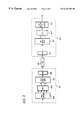
- FIG. 3 is a block diagram illustrating a DMT transmitter and receiver for sending and receiving differentially coded DMT signals according to an embodiment of the present invention.
- FIG. 4 is a diagram illustrating the differential coding and decoding of bit pairs by the DMT transmitter and receiver of FIG. 3, respectively, according to an embodiment of the present invention.
- FIG. 2 is a diagram of a local area network 10 implemented in a home or similar customer premises environment using network media 14 according to an embodiment of the present invention.
- the network may use a variety of different physical lines for the network media 14 , such as coaxial cable, multi-pair cables, power lines, optical fiber or RF wireless communication links.
- the media 14 comprises twisted pair telephone wiring, commonly available in the home or office.
- the network 10 includes network stations 12 a , 12 b and 12 c that are connected to a telephone line (twisted pair) wiring 14 , via RJ-11 phone jacks 16 a , 16 b and 16 c respectively.
- a telephone 18 connected to the RJ-11 phone jack 16 d may continue to make phone calls while one or more of the stations 12 are communicating data.
- each home network station 12 comprises a data device 20 , for example a personal computer, printer, or intelligent consumer electronics device.
- Each station 12 also includes a physical layer (PHY) transceiver 22 , a media access (MAC) layer 24 , and an operating system (OS) layer 26 that performs higher layer functions according to the OSI reference model.
- PHY physical layer
- MAC media access
- OS operating system
- the PHY transceiver utilizes digital signal processing techniques to implement discrete multi-tone transport of digital data over the telephone wiring 14 .
- the stations 12 communicate by transmitting network data modulated into the analog network signals in accord with the invention.
- the physical layer transmitter transmits data as discrete multi-tone (DMT) symbols carrying the actual digital communication data.
- the physical layer receiver receives and processes these signals and demodulates the DMT symbols to recover the data, described in further detail below.
- DMT discrete multi-tone
- the network 10 is envisioned as a home network, although it will be apparent that the network may be used in a variety of other customer locations. In many such installations, the network 10 will provide random access to the local area network media 14 for data communications between the stations 12 within the customer premises. However, it is within the scope of the invention to utilize the DMT-based data communications to access external networks.
- the customer premises wiring 14 connects through a network interface device (NID) 30 to a subscriber's telephone line 31 .
- the line 31 connects to a central office (CO) switch 32 of the public switched telephone network.
- the switch 32 provides normal voice-grade telephone services, for example for communications using the telephone 18 .
- the line 31 may also transport DMT signals at appropriate frequencies for access to another network.
- the telephone network operator or another service provider would have a digital terminal unit 34 coupled to the subscriber's telephone line 31 .
- the device 34 provides access to an external wide area data network, for example using ATM or SMDS to gain access to the public packet switched data network 36 commonly referred to as the Internet.
- the digital terminal unit 34 includes a physical layer (PHY) transceiver 22 N , a media access (MAC) layer 24 N , and an operating system (OS) layer 26 N that perform functions similar to the transceiver 22 , the MAC 24 and the OS 26 in each of the home stations 12 , respectively
- the data device takes the form of a network interface 38 for providing the appropriate interface to the physical transport media of the higher level data network 36 .
- the DMT transmitters and receivers in the DMT PIY transceivers 22 utilize digital signal processors, to generate and/or demodulate complex analog waveforms carrying bits of data modulated onto individual tones within the available bandwidth.
- the transmitter generates a DMT symbol by supplying a number of samples through a digital to analog converter to produce the analog waveform of the symbol, having the mathematical properties necessary to represent the data carried by the symbol.
- the receiver samples a received waveform and processes the time-domain values of the samples. This processing derives frequency-domain data, enabling the receiver to then detect the data bits transported on each tone contained within the symbol.
- all PHY transceivers 22 of all stations 12 , 34 on the line receive all transmissions relating to data communications made over the line 14 , 31 .
- the ID and control waveform is used to physically assert control over the random access media.
- All receivers demodulate the packet data within the DMT signals. Packet addresses, corresponding to the sending and receiving stations 12 or 34 for a given communication reside within the packet data.
- FIG. 3 provides a simplified block diagram of the functional elements of a DMT transmitter and DMT receiver for use in the PHY transceivers 22 of the network 10 (FIG. 2 ).
- the transmitter 101 receives a digital bit stream from a digital source, for example a host central processing unit (CPU) (not shown).
- the bit stream enters the differential encoder 103 , which maps a prescribed number of bits of the bit stream (e.g., 2) to points on the complex plane (i.e., constellation points), in similar fashion to the operating principles of QPSK (quadrature phase shift keying).
- QPSK quadrature phase shift keying
- the differential encoder 103 encodes the difference between a current constellation point with a previous constellation point. That is, the phase difference between constellation points defines the encoding of the bits.
- FIG. 4 is a diagram illustrating in further detail the differential coding of a group of bits according to an embodiment of the present invention.
- FIG. 4 assumes that the differential encoder 103 maps a group of two bits (i.e., a bit pair) to a four-point Constellation, although higher numbers of bits may be mapped to higher-order constellations (e.g., 3 bits to 8-point, 4 bits to 16-point, 5 bits to 32-point, etc.).
- the differential coding begins by the generation of a constellation point 200 by the differential encoder 103 .
- the actual position of the constellation point 200 in quadrant Q 1 , Q 2 , Q 3 , or Q 4 may be arbitrary, for example during initial transmission of a beginning of a bit stream.
- transmission of the constellation point 200 on the media channel 125 results in attenuation and phase distortion that causes the receiver 111 to detect the Constellation point 200 at location 202 .
- the differential encoder 103 then performs differential coding by phase-shifting 203 the new constellation point 204 relative to the position of the constellation point 200 and based on the value of the supplied bit pair. For example, a bit-pair value of 00 causes no phase rotation (0 degrees); a bit-pair value of 01 causes a phase rotation of 90 degrees; a bit-pair value of 11 causes a phase rotation of 180 degrees; and a bit-pair value of 10 causes a phase rotation of 270 degrees. As shown in FIG. 4, the 90 degree phase shift 203 of constellation point 204 by the differential encoder 103 , relative to the constellation point 200 , corresponds to a bit-pair value of 01 .
- the consecutive transmission of the constellation point 204 on the same DMT tone results in substantially the same attenuation and phase distortion, causing the receiver 111 to detect the constellation point 204 at location 206 .
- the phase difference between locations 202 and 206 is the same as the phase rotation between the two consecutive transmitted constellation points 200 and 204 , enabling the differential decoder 121 within the receiver 111 to accurately decode the bit-pair as 01 .
- the bit pair is encoded in the phase position of constellation point 204 relative to point 200 .
- differential coding which encodes the information on the amplitude and phase difference between transmitted constellation points, enables the decoding of the transmitted information by the differential decoder 121 without knowledge of the media channel characteristics (e.g., attenuation and phase distortion).
- the differential encoding of the information on consecutive symbols effectively updates the constellation rotation, reducing the impact caused by differences in the transmitter clock and the receiver clock.
- the differential encoder 103 encodes a bit stream in bit sequences of 2-bits using 256 frequencies (or tones); as a result, a symbol represents 512 bits. Because the encoding scheme focuses on amplitude and phase differences, absolute signal values are not needed for correctly detecting and decoding the received symbols. As such, this technique eliminates the need for a frequency domain equalizer (FEQ) to compensate for amplitude and phase distortion caused by the channel 125 .
- FEQ frequency domain equalizer
- the output of the differential encoder 103 is a parallel array of “complex numbers.” These complex numbers are input in a parallel manner into an Inverse Fast Fourier Transform (IFFT) logic 105 .
- the IFFT logic 105 converts the complex numbers into time-domain waveform samples, which are then supplied to an parallel-to-serial logic 107 .
- the parallel-to-serial logic 107 basically arranges the time-domain waveform samples into a serial stream. A guard band or cyclic-prefix can be prepended to this serial stream before entering the analog front end (AFE) circuit 109 to minimize intersymbol interference (ISI). ISI is an overlapping of waveforms that distorts all symbols involved, potentially corrupting all of them.
- the AFE circuit 109 performs digital to analog (D/A) conversion and sends the symbol, which includes the differentially encoded signals, over channel 125 to receiver 111 .
- D/A digital to analog
- the noise within the in-home wiring is quite pronounced. Because of the reflections caused by improper terminations, deep nulls are formed at certain frequencies on the home network. As the symbol propagates through the channel 125 , the symbol is attenuated when it arrives at the receiver 111 .
- the receiver 111 receives the symbol using the AFE circuit 113 , which is responsible for filtering the analog waveform of the symbol and converting it to a digital equivalent. After processing of the received signal by the AFE 113 , the digitized or discrete waveforms are to an input serial-to-parallel logic 117 for conversion to a parallel array of time-domain data.
- a Fast Fourier Transform logic 119 converts the time domain data back to complex numbers, which are then mapped by the differential decoder and slicer 121 to corresponding bit sequences as described above with respect to FIG. 4 to recover the original data bits.
- the bits of data derived from all of the tones of one symbol are combined then into a serial bit stream and output by the receiver 111 .
- DQPSK differential quadrature phase-shift keying type modulation
- the DMT transmitter and the DMT receiver may be implemented in a number of different ways. For example, they be implemented as specifically engineered chips having logic circuits and other components for performing the functions described above. Alternatively, one or both may be implemented using a general purpose digital signal processor and appropriate programming.
Abstract
Description
Claims (18)
Priority Applications (1)
| Application Number | Priority Date | Filing Date | Title |
|---|---|---|---|
| US09/286,989 US6434188B1 (en) | 1999-04-07 | 1999-04-07 | Differential encoding arrangement for a discrete multi-tone transmission system |
Applications Claiming Priority (1)
| Application Number | Priority Date | Filing Date | Title |
|---|---|---|---|
| US09/286,989 US6434188B1 (en) | 1999-04-07 | 1999-04-07 | Differential encoding arrangement for a discrete multi-tone transmission system |
Publications (1)
| Publication Number | Publication Date |
|---|---|
| US6434188B1 true US6434188B1 (en) | 2002-08-13 |
Family
ID=23101001
Family Applications (1)
| Application Number | Title | Priority Date | Filing Date |
|---|---|---|---|
| US09/286,989 Expired - Lifetime US6434188B1 (en) | 1999-04-07 | 1999-04-07 | Differential encoding arrangement for a discrete multi-tone transmission system |
Country Status (1)
| Country | Link |
|---|---|
| US (1) | US6434188B1 (en) |
Cited By (11)
| Publication number | Priority date | Publication date | Assignee | Title |
|---|---|---|---|---|
| US20010047434A1 (en) * | 2000-03-01 | 2001-11-29 | Ming-Kang Liu | xDSL communications systems using shared/multi-function task blocks |
| US20020023086A1 (en) * | 2000-06-30 | 2002-02-21 | Ponzio, Jr. Frank J. | System and method for providing signaling quality and integrity of data content |
| US20040247048A1 (en) * | 2003-06-04 | 2004-12-09 | Dimsdle Jeffrey William | Method of differential-phase/absolute-amplitude QAM |
| US20040247039A1 (en) * | 2003-06-04 | 2004-12-09 | Dimsdle Jeffrey William | Method of differential-phase/absolute-amplitude QAM |
| US20070165832A1 (en) * | 2001-05-01 | 2007-07-19 | Jules Insler | Methods and systems for high speed broadband digital link |
| US20070230594A1 (en) * | 2006-03-31 | 2007-10-04 | Mo Shaomin S | Multi-band OFDM UWB communication systems having improved frequency diversity |
| US20080240299A1 (en) * | 2007-03-28 | 2008-10-02 | Xiaojing Huang | Demodulation of 16-QAM, DCM data symbols using two hybrid-QPSK constellations |
| US20090052519A1 (en) * | 2005-10-05 | 2009-02-26 | Lg Electronics Inc. | Method of Processing a Signal and Apparatus for Processing a Signal |
| US8995568B1 (en) * | 2008-09-05 | 2015-03-31 | Marvell International Ltd. | Phase transformation of repeated signals |
| CN111010237A (en) * | 2018-10-08 | 2020-04-14 | 诺基亚通信公司 | Geometric constellation shaping for optical data transmission |
| US11368348B2 (en) * | 2018-11-19 | 2022-06-21 | Huawei Technologies Co., Ltd. | Signal transmission method and apparatus |
Citations (4)
| Publication number | Priority date | Publication date | Assignee | Title |
|---|---|---|---|---|
| US5166924A (en) * | 1990-03-06 | 1992-11-24 | Mercury Digital Communications, Inc. | Echo cancellation in multi-frequency differentially encoded digital communications |
| US5774500A (en) * | 1995-12-08 | 1998-06-30 | Board Of Trustees, The Leland Stanford Jr., University | Multi-channel trellis shaper |
| US6192026B1 (en) * | 1998-02-06 | 2001-02-20 | Cisco Systems, Inc. | Medium access control protocol for OFDM wireless networks |
| US6252912B1 (en) * | 1997-12-24 | 2001-06-26 | General Dynamics Government Systems Corporation | Adaptive predistortion system |
-
1999
- 1999-04-07 US US09/286,989 patent/US6434188B1/en not_active Expired - Lifetime
Patent Citations (4)
| Publication number | Priority date | Publication date | Assignee | Title |
|---|---|---|---|---|
| US5166924A (en) * | 1990-03-06 | 1992-11-24 | Mercury Digital Communications, Inc. | Echo cancellation in multi-frequency differentially encoded digital communications |
| US5774500A (en) * | 1995-12-08 | 1998-06-30 | Board Of Trustees, The Leland Stanford Jr., University | Multi-channel trellis shaper |
| US6252912B1 (en) * | 1997-12-24 | 2001-06-26 | General Dynamics Government Systems Corporation | Adaptive predistortion system |
| US6192026B1 (en) * | 1998-02-06 | 2001-02-20 | Cisco Systems, Inc. | Medium access control protocol for OFDM wireless networks |
Cited By (37)
| Publication number | Priority date | Publication date | Assignee | Title |
|---|---|---|---|---|
| US7818748B2 (en) | 2000-03-01 | 2010-10-19 | Realtek Semiconductor Corporation | Programmable task scheduler |
| US7085285B2 (en) | 2000-03-01 | 2006-08-01 | Realtek Semiconductor Corp. | xDSL communications systems using shared/multi-function task blocks |
| US20020010810A1 (en) * | 2000-03-01 | 2002-01-24 | Ming-Kang Liu | xDSL function ASIC processor & method of operation |
| US8325751B2 (en) | 2000-03-01 | 2012-12-04 | Realtek Semiconductor Corp. | Mixed hardware/software architecture and method for processing communications |
| US20020008256A1 (en) * | 2000-03-01 | 2002-01-24 | Ming-Kang Liu | Scaleable architecture for multiple-port, system-on-chip ADSL communications systems |
| US7295571B2 (en) | 2000-03-01 | 2007-11-13 | Realtek Semiconductor Corp. | xDSL function ASIC processor and method of operation |
| US20020049581A1 (en) * | 2000-03-01 | 2002-04-25 | Ming-Kang Liu | Physical medium dependent sub-system with shared resources for multiport xDSL system |
| US20010049757A1 (en) * | 2000-03-01 | 2001-12-06 | Ming-Kang Liu | Programmable task scheduler for use with multiport xDSL processing system |
| US20010047434A1 (en) * | 2000-03-01 | 2001-11-29 | Ming-Kang Liu | xDSL communications systems using shared/multi-function task blocks |
| US20050071800A1 (en) * | 2000-03-01 | 2005-03-31 | Realtek Semiconductor Corporation | Mixed hardware/sofware architecture and method for processing xDSL communications |
| US6986073B2 (en) | 2000-03-01 | 2006-01-10 | Realtek Semiconductor Corp. | System and method for a family of digital subscriber line (XDSL) signal processing circuit operating with an internal clock rate that is higher than all communications ports operating with a plurality of port sampling clock rates |
| US7032223B2 (en) | 2000-03-01 | 2006-04-18 | Realtek Semiconductor Corp. | Transport convergence sub-system with shared resources for multiport xDSL system |
| US7075941B2 (en) | 2000-03-01 | 2006-07-11 | Real Communications, Inc. | Scaleable architecture for multiple-port, system-on-chip ADSL communications systems |
| US20020010849A1 (en) * | 2000-03-01 | 2002-01-24 | Ming-Kang Liu | Data object architecture and method for xDSL ASIC processor |
| US20060203843A1 (en) * | 2000-03-01 | 2006-09-14 | Realtek Semiconductor Corp. | xDSL function ASIC processor & method of operation |
| US7200138B2 (en) * | 2000-03-01 | 2007-04-03 | Realtek Semiconductor Corporation | Physical medium dependent sub-system with shared resources for multiport xDSL system |
| US20020023086A1 (en) * | 2000-06-30 | 2002-02-21 | Ponzio, Jr. Frank J. | System and method for providing signaling quality and integrity of data content |
| US20070165832A1 (en) * | 2001-05-01 | 2007-07-19 | Jules Insler | Methods and systems for high speed broadband digital link |
| US20040247039A1 (en) * | 2003-06-04 | 2004-12-09 | Dimsdle Jeffrey William | Method of differential-phase/absolute-amplitude QAM |
| US7239674B2 (en) * | 2003-06-04 | 2007-07-03 | Honeywell Federal Manufacturing & Technologies, Llc | Method of differential-phase/absolute-amplitude QAM |
| US20040247048A1 (en) * | 2003-06-04 | 2004-12-09 | Dimsdle Jeffrey William | Method of differential-phase/absolute-amplitude QAM |
| US7277494B2 (en) * | 2003-06-04 | 2007-10-02 | Honeywell Federal Manufacturing & Technologies, Llc | Method of differential-phase/absolute-amplitude QAM |
| US8755442B2 (en) | 2005-10-05 | 2014-06-17 | Lg Electronics Inc. | Method of processing a signal and apparatus for processing a signal |
| US20090052519A1 (en) * | 2005-10-05 | 2009-02-26 | Lg Electronics Inc. | Method of Processing a Signal and Apparatus for Processing a Signal |
| US20090161695A1 (en) * | 2005-10-05 | 2009-06-25 | Oh Hyen O | Method of Processing a Signal and Apparatus for Processing a Signal |
| US20090225782A1 (en) * | 2005-10-05 | 2009-09-10 | Lg Electronics Inc. | Method of Processing a Signal and Apparatus for Processing a Signal |
| US7813380B2 (en) * | 2005-10-05 | 2010-10-12 | Lg Electronics Inc. | Method of processing a signal and apparatus for processing a signal |
| US8203930B2 (en) | 2005-10-05 | 2012-06-19 | Lg Electronics Inc. | Method of processing a signal and apparatus for processing a signal |
| US20070230594A1 (en) * | 2006-03-31 | 2007-10-04 | Mo Shaomin S | Multi-band OFDM UWB communication systems having improved frequency diversity |
| US7653141B2 (en) * | 2006-03-31 | 2010-01-26 | Panasonic Corporation | Multi-band OFDM UWB communication systems having improved frequency diversity |
| US8102930B2 (en) * | 2007-03-28 | 2012-01-24 | Agere Systems Inc. | Demodulation of 16-QAM, DCM data symbols using two hybrid-QPSK constellations |
| US20120051415A1 (en) * | 2007-03-28 | 2012-03-01 | Agere Systems Inc. | Demodulation of 16-qam, dcm data symbols using two hybrid-qpsk constellations |
| US20080240299A1 (en) * | 2007-03-28 | 2008-10-02 | Xiaojing Huang | Demodulation of 16-QAM, DCM data symbols using two hybrid-QPSK constellations |
| US8995568B1 (en) * | 2008-09-05 | 2015-03-31 | Marvell International Ltd. | Phase transformation of repeated signals |
| US9294941B1 (en) | 2008-09-05 | 2016-03-22 | Marvell International Ltd. | Phase transformation of repeated signals |
| CN111010237A (en) * | 2018-10-08 | 2020-04-14 | 诺基亚通信公司 | Geometric constellation shaping for optical data transmission |
| US11368348B2 (en) * | 2018-11-19 | 2022-06-21 | Huawei Technologies Co., Ltd. | Signal transmission method and apparatus |
Similar Documents
| Publication | Publication Date | Title |
|---|---|---|
| US6219378B1 (en) | Digital subscriber line modem initialization | |
| US6704317B1 (en) | Multi-carrier LAN modem server | |
| US6549512B2 (en) | MDSL DMT architecture | |
| US6853637B1 (en) | Converged home gateway | |
| US5987061A (en) | Modem initialization process for line code and rate selection in DSL data communication | |
| US6590893B1 (en) | Adaptive transmission system in a network | |
| US6069899A (en) | Home area network system and method | |
| US6434119B1 (en) | Initializing communications in systems using multi-carrier modulation | |
| US6307889B1 (en) | Method for fast initialization of multicarrier system and point-to-multipoint transfer of multicarrier signal in digital subscriber line | |
| US6891887B1 (en) | Multi-carrier LAN adapter device using interpolative equalizer | |
| US6434188B1 (en) | Differential encoding arrangement for a discrete multi-tone transmission system | |
| US20040174903A1 (en) | Reduced symbol rate handshake signaling in ADSL systems | |
| US6442173B1 (en) | Timing recovery scheme for a discrete multitone transmission system | |
| US6075795A (en) | Collision detection system for multiple stations in discrete multi-tone data communications network | |
| US6603811B1 (en) | Low complexity frequency domain equalizer having fast re-lock | |
| US6535550B1 (en) | Transceiver with variable width cyclic prefix | |
| US6456602B1 (en) | Method and apparatus for achieving frequency diversity by use of multiple images | |
| US6690666B1 (en) | Packet modulation for DSL | |
| US6577598B1 (en) | Methods and apparatus for channel adaptation in a DMT based system | |
| US6339599B1 (en) | Collision handling scheme for discrete multi-tone data communications network | |
| EP1410541A1 (en) | Improved scheme for the initialization of adsl modems | |
| US7076002B1 (en) | Method and apparatus for symbol boundary synchronization | |
| US6175316B1 (en) | Bin-to-bin differential encoding apparatus and method for a discrete multi-tone transmission system | |
| US6449262B1 (en) | Method and apparatus for frequency shifting with a clock signal | |
| US6483869B1 (en) | Frequency decimated DMT modulation modem |
Legal Events
| Date | Code | Title | Description |
|---|---|---|---|
| AS | Assignment |
Owner name: ADVANCED MICRO DEVICES, INC., CALIFORNIA Free format text: ASSIGNMENT OF ASSIGNORS INTEREST;ASSIGNORS:HWANG, CHIEN-MEEN;CHANG, HUNGMING;BARSOUM, MAGED F.;AND OTHERS;REEL/FRAME:009885/0476 Effective date: 19990406 |
|
| AS | Assignment |
Owner name: MORGAN STANLEY & CO. INCORPORATED, NEW YORK Free format text: SECURITY INTEREST;ASSIGNOR:LEGERITY, INC.;REEL/FRAME:011601/0539 Effective date: 20000804 |
|
| AS | Assignment |
Owner name: LEGERITY, INC., TEXAS Free format text: ASSIGNMENT OF ASSIGNORS INTEREST;ASSIGNOR:ADVANCED MICRO DEVICES, INC.;REEL/FRAME:011700/0686 Effective date: 20000731 |
|
| STCF | Information on status: patent grant |
Free format text: PATENTED CASE |
|
| AS | Assignment |
Owner name: MORGAN STANLEY & CO. INCORPORATED, AS FACILITY COL Free format text: SECURITY AGREEMENT;ASSIGNORS:LEGERITY, INC.;LEGERITY HOLDINGS, INC.;LEGERITY INTERNATIONAL, INC.;REEL/FRAME:013372/0063 Effective date: 20020930 |
|
| FPAY | Fee payment |
Year of fee payment: 4 |
|
| AS | Assignment |
Owner name: LEGERITY, INC., TEXAS Free format text: RELEASE BY SECURED PARTY;ASSIGNOR:MORGAN STANLEY SENIOR FUNDING INC;REEL/FRAME:019640/0676 Effective date: 20070803 Owner name: LEGERITY, INC.,TEXAS Free format text: RELEASE BY SECURED PARTY;ASSIGNOR:MORGAN STANLEY SENIOR FUNDING INC;REEL/FRAME:019640/0676 Effective date: 20070803 |
|
| FPAY | Fee payment |
Year of fee payment: 8 |
|
| AS | Assignment |
Owner name: ZARLINK SEMICONDUCTOR (U.S.) INC., TEXAS Free format text: MERGER;ASSIGNOR:LEGERITY, INC.;REEL/FRAME:031746/0171 Effective date: 20071130 Owner name: MICROSEMI SEMICONDUCTOR (U.S.) INC., TEXAS Free format text: CHANGE OF NAME;ASSIGNOR:ZARLINK SEMICONDUCTOR (U.S.) INC.;REEL/FRAME:031746/0214 Effective date: 20111121 |
|
| AS | Assignment |
Owner name: MORGAN STANLEY & CO. LLC, NEW YORK Free format text: PATENT SECURITY AGREEMENT;ASSIGNOR:MICROSEMI SEMICONDUCTOR (U.S.) INC.;REEL/FRAME:031729/0667 Effective date: 20131125 |
|
| FPAY | Fee payment |
Year of fee payment: 12 |
|
| AS | Assignment |
Owner name: BANK OF AMERICA, N.A., AS SUCCESSOR AGENT, NORTH C Free format text: NOTICE OF SUCCESSION OF AGENCY;ASSIGNOR:ROYAL BANK OF CANADA (AS SUCCESSOR TO MORGAN STANLEY & CO. LLC);REEL/FRAME:035657/0223 Effective date: 20150402 |
|
| AS | Assignment |
Owner name: MICROSEMI COMMUNICATIONS, INC. (F/K/A VITESSE SEMI Free format text: RELEASE BY SECURED PARTY;ASSIGNOR:BANK OF AMERICA, N.A.;REEL/FRAME:037558/0711 Effective date: 20160115 Owner name: MICROSEMI CORPORATION, CALIFORNIA Free format text: RELEASE BY SECURED PARTY;ASSIGNOR:BANK OF AMERICA, N.A.;REEL/FRAME:037558/0711 Effective date: 20160115 Owner name: MICROSEMI SOC CORP., A CALIFORNIA CORPORATION, CAL Free format text: RELEASE BY SECURED PARTY;ASSIGNOR:BANK OF AMERICA, N.A.;REEL/FRAME:037558/0711 Effective date: 20160115 Owner name: MICROSEMI CORP.-ANALOG MIXED SIGNAL GROUP, A DELAW Free format text: RELEASE BY SECURED PARTY;ASSIGNOR:BANK OF AMERICA, N.A.;REEL/FRAME:037558/0711 Effective date: 20160115 Owner name: MICROSEMI FREQUENCY AND TIME CORPORATION, A DELAWA Free format text: RELEASE BY SECURED PARTY;ASSIGNOR:BANK OF AMERICA, N.A.;REEL/FRAME:037558/0711 Effective date: 20160115 Owner name: MICROSEMI CORP.-MEMORY AND STORAGE SOLUTIONS (F/K/ Free format text: RELEASE BY SECURED PARTY;ASSIGNOR:BANK OF AMERICA, N.A.;REEL/FRAME:037558/0711 Effective date: 20160115 Owner name: MICROSEMI SEMICONDUCTOR (U.S.) INC., A DELAWARE CO Free format text: RELEASE BY SECURED PARTY;ASSIGNOR:BANK OF AMERICA, N.A.;REEL/FRAME:037558/0711 Effective date: 20160115 |
|
| AS | Assignment |
Owner name: MORGAN STANLEY SENIOR FUNDING, INC., NEW YORK Free format text: PATENT SECURITY AGREEMENT;ASSIGNORS:MICROSEMI CORPORATION;MICROSEMI SEMICONDUCTOR (U.S.) INC. (F/K/A LEGERITY, INC., ZARLINK SEMICONDUCTOR (V.N.) INC., CENTELLAX, INC., AND ZARLINK SEMICONDUCTOR (U.S.) INC.);MICROSEMI FREQUENCY AND TIME CORPORATION (F/K/A SYMMETRICON, INC.);AND OTHERS;REEL/FRAME:037691/0697 Effective date: 20160115 |
|
| AS | Assignment |
Owner name: MICROSEMI FREQUENCY AND TIME CORPORATION, CALIFORN Free format text: RELEASE BY SECURED PARTY;ASSIGNOR:MORGAN STANLEY SENIOR FUNDING, INC.;REEL/FRAME:046251/0391 Effective date: 20180529 Owner name: MICROSEMI SOC CORP., CALIFORNIA Free format text: RELEASE BY SECURED PARTY;ASSIGNOR:MORGAN STANLEY SENIOR FUNDING, INC.;REEL/FRAME:046251/0391 Effective date: 20180529 Owner name: MICROSEMI COMMUNICATIONS, INC., CALIFORNIA Free format text: RELEASE BY SECURED PARTY;ASSIGNOR:MORGAN STANLEY SENIOR FUNDING, INC.;REEL/FRAME:046251/0391 Effective date: 20180529 Owner name: MICROSEMI CORP. - POWER PRODUCTS GROUP, CALIFORNIA Free format text: RELEASE BY SECURED PARTY;ASSIGNOR:MORGAN STANLEY SENIOR FUNDING, INC.;REEL/FRAME:046251/0391 Effective date: 20180529 Owner name: MICROSEMI CORPORATION, CALIFORNIA Free format text: RELEASE BY SECURED PARTY;ASSIGNOR:MORGAN STANLEY SENIOR FUNDING, INC.;REEL/FRAME:046251/0391 Effective date: 20180529 Owner name: MICROSEMI SEMICONDUCTOR (U.S.), INC., CALIFORNIA Free format text: RELEASE BY SECURED PARTY;ASSIGNOR:MORGAN STANLEY SENIOR FUNDING, INC.;REEL/FRAME:046251/0391 Effective date: 20180529 Owner name: MICROSEMI CORP. - RF INTEGRATED SOLUTIONS, CALIFOR Free format text: RELEASE BY SECURED PARTY;ASSIGNOR:MORGAN STANLEY SENIOR FUNDING, INC.;REEL/FRAME:046251/0391 Effective date: 20180529 |