US6429902B1 - Method and apparatus for audio and video end-to-end synchronization - Google Patents
Method and apparatus for audio and video end-to-end synchronization Download PDFInfo
- Publication number
- US6429902B1 US6429902B1 US09/457,117 US45711799A US6429902B1 US 6429902 B1 US6429902 B1 US 6429902B1 US 45711799 A US45711799 A US 45711799A US 6429902 B1 US6429902 B1 US 6429902B1
- Authority
- US
- United States
- Prior art keywords
- increment
- interval
- pcr
- difference
- ltc
- Prior art date
- Legal status (The legal status is an assumption and is not a legal conclusion. Google has not performed a legal analysis and makes no representation as to the accuracy of the status listed.)
- Expired - Lifetime
Links
Images


Classifications
-
- H—ELECTRICITY
- H04—ELECTRIC COMMUNICATION TECHNIQUE
- H04N—PICTORIAL COMMUNICATION, e.g. TELEVISION
- H04N21/00—Selective content distribution, e.g. interactive television or video on demand [VOD]
- H04N21/40—Client devices specifically adapted for the reception of or interaction with content, e.g. set-top-box [STB]; Operations thereof
- H04N21/43—Processing of content or additional data, e.g. demultiplexing additional data from a digital video stream; Elementary client operations, e.g. monitoring of home network or synchronising decoder's clock; Client middleware
- H04N21/4302—Content synchronisation processes, e.g. decoder synchronisation
- H04N21/4305—Synchronising client clock from received content stream, e.g. locking decoder clock with encoder clock, extraction of the PCR packets
-
- H—ELECTRICITY
- H04—ELECTRIC COMMUNICATION TECHNIQUE
- H04N—PICTORIAL COMMUNICATION, e.g. TELEVISION
- H04N21/00—Selective content distribution, e.g. interactive television or video on demand [VOD]
- H04N21/20—Servers specifically adapted for the distribution of content, e.g. VOD servers; Operations thereof
- H04N21/23—Processing of content or additional data; Elementary server operations; Server middleware
- H04N21/236—Assembling of a multiplex stream, e.g. transport stream, by combining a video stream with other content or additional data, e.g. inserting a URL [Uniform Resource Locator] into a video stream, multiplexing software data into a video stream; Remultiplexing of multiplex streams; Insertion of stuffing bits into the multiplex stream, e.g. to obtain a constant bit-rate; Assembling of a packetised elementary stream
- H04N21/2368—Multiplexing of audio and video streams
-
- H—ELECTRICITY
- H04—ELECTRIC COMMUNICATION TECHNIQUE
- H04N—PICTORIAL COMMUNICATION, e.g. TELEVISION
- H04N21/00—Selective content distribution, e.g. interactive television or video on demand [VOD]
- H04N21/20—Servers specifically adapted for the distribution of content, e.g. VOD servers; Operations thereof
- H04N21/23—Processing of content or additional data; Elementary server operations; Server middleware
- H04N21/242—Synchronization processes, e.g. processing of PCR [Program Clock References]
-
- H—ELECTRICITY
- H04—ELECTRIC COMMUNICATION TECHNIQUE
- H04N—PICTORIAL COMMUNICATION, e.g. TELEVISION
- H04N21/00—Selective content distribution, e.g. interactive television or video on demand [VOD]
- H04N21/40—Client devices specifically adapted for the reception of or interaction with content, e.g. set-top-box [STB]; Operations thereof
- H04N21/43—Processing of content or additional data, e.g. demultiplexing additional data from a digital video stream; Elementary client operations, e.g. monitoring of home network or synchronising decoder's clock; Client middleware
- H04N21/434—Disassembling of a multiplex stream, e.g. demultiplexing audio and video streams, extraction of additional data from a video stream; Remultiplexing of multiplex streams; Extraction or processing of SI; Disassembling of packetised elementary stream
- H04N21/4341—Demultiplexing of audio and video streams
-
- H—ELECTRICITY
- H04—ELECTRIC COMMUNICATION TECHNIQUE
- H04N—PICTORIAL COMMUNICATION, e.g. TELEVISION
- H04N5/00—Details of television systems
- H04N5/04—Synchronising
-
- H—ELECTRICITY
- H04—ELECTRIC COMMUNICATION TECHNIQUE
- H04N—PICTORIAL COMMUNICATION, e.g. TELEVISION
- H04N21/00—Selective content distribution, e.g. interactive television or video on demand [VOD]
- H04N21/40—Client devices specifically adapted for the reception of or interaction with content, e.g. set-top-box [STB]; Operations thereof
- H04N21/41—Structure of client; Structure of client peripherals
- H04N21/426—Internal components of the client ; Characteristics thereof
Definitions
- the present invention relates to end-to-end signal synchronization between an encoder and a decoder.
- Moving images and associated sound may be transmitted as audio/visual (A/V) signals and represented to viewers by receivers having video displays and audio speakers.
- a Set-Top Box (STB) represents an example device commonly used to receive such A/V signals.
- the STB so called because this standalone signal converter is typically placed above the video display of a television receiver, may receive transmitted encoded A/V signals (sent by cable, broadcast or via satellite) and decode these signals for displaying on the television.
- A/V signals to be enjoyed by a consumer without degradation in image frames or sound fidelity
- the audio and video bitstreams must be synchronized based on standards used in the industry.
- FIG. 1 illustrates an example.
- a first square-wave 10 has a first step rise event 12 corresponding to a particular time 14 .
- the wavelength of the first square-wave provides a measure of its period 16 .
- a second square-wave 18 has a second step rise event 20 a finite time interval later than the first step rise event 12 , and this difference may be described as the skew 22 .
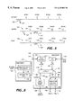
- Video data 24 are input to a video encoder 26 yielding a video elementary stream 28 that is input to a video packetizer 30 , producing a video packetized elementary stream (PES) 32 .
- the corresponding audio data 34 are input to an audio encoder 36 to produce an audio elementary stream 38 that is input to an audio packetizer 40 producing an audio PES 42 .
- the video PES 32 and audio PES 42 are input to a stream multiplexer (MUX) 44 from which a resulting bitstream 46 is transmitted.
- MUX stream multiplexer
- Synchronization of an encoder and a decoder involves sending program clock reference (PCR) time stamps (or counts) embedded by the encoder in the A/V transport bitstream and received by the decoder on the STB.
- PCR time stamps provide a sample of the encoder clock count sent in the transport stream packet.
- the encoder clocks drive a constantly running binary counter. The value of these counters is sampled periodically and placed in the header adaptation fields as the PCR.
- the decoder compares the received PCR time-stamps from the packet header to its corresponding time stamps from a local time counter (LTC), in order to synchronize the A/V presentation for decoding.
- LTC local time counter
- the short-term history of the PCR increments relative to their LTC counterparts provides the relation between the local decoder's clock and the encoder's clock.
- the difference may represent skew or phase error.
- the decoder's system clock is adjusted to match that of the encoder to avoid loss of A/V bitstream data.
- ISO-13818-1 titled Information Technology—Generic Coding of Moving Pictures and Associated Audio Information, Part 1 : Systems (November 1994).
- ISO-13818-1 specifies a multiplexed structure for combining audio and video data along with the representation of the timing information needed to replay synchronized sequences in real-time.
- Compression of the A/V bitstream is standardized by the Moving Photographers Expert Group (MPEG), e.g., standards such as MPEG-1, MPEG-2, MPEG-4 and MPEG-7.
- MPEG Moving Photographers Expert Group
- the target timebase frequency for the ISO-13181-1 system clock is 27 megahertz (MHz) with a variation of ⁇ 30 parts per million (ppm).
- the PCR time stamp used for the MPEG-2 transport standard, represents a small portion of a 188-byte packet as illustrated in FIG. 3 showing the packet 48 divided into a header 50 and a payload 52 .
- the header is subdivided into several fields, in the first expanded row 54 , including an adaptation field 56 .
- Expansion of the adaptation field 56 yields a second expanded row 58 , which includes an entry for optional fields 60 .
- Expansion of the optional fields 60 yields a third expanded row 62 , within which is contained the PCR 64 .
- the common synchronization method for coder/decoder (codec) end-to-end communication uses an external VCxO component to control the STB master clock frequency that establishes the encoder operating frequency, and to synchronize the decoder operating frequency so as to match the encoder operating frequency.
- the VCxO is an oscillator with a dynamic range connected to a voltage control input pin.
- the decoder can regulate its clock frequency by altering the VCxO control input voltage in response to the encoder clock PCR time stamps received by the decoder.
- the codec clock comparison may be illustrated in FIG. 4 in which a remotely located video encoder 66 receives a input video signal 68 and outputs an elementary stream 70 that is combined with the frequency of the encoder clock 72 for the transport stream formation device 74 .
- the bitstream 76 includes a first packet 78 and a second packet 80 separated by n bits of data 82 transmitted over the time between packets t n .
- PCR time stamps labeled “X” 84 and “X+t n ” 86 are embedded within the first and second packets 78 and 80 respectively.
- the bitstream 76 is received by a transport stream decoder 88 , which forwards the PCR 90 and the LTC 92 from the local clock 94 to the time-difference comparison device 96 .
- the time-difference is sent to a variable oscillator 100 that uses the filtered time-difference to adjust the local clock 94 so as to be synchronized with the encoder clock 72 .
- a method and apparatus for synchronization of an audio/visual bitstream is transmitted by an encoder and received by a decoder by employing duplication or elimination of audio samples and video pixels.
- the invention enables clock synchronization between the encoder and a decoder with an unregulated clock oscillator so as to control the data reader by skipping ahead (eliminating a data element) or to pause (duplicating a data element) depending on whether the encoder clock is faster or slower than the decoder clock.
- FIG. 1 is a timing diagram of two square waves illustrating skew.
- FIG. 2 is a block diagram of a scheme for A/V multiplexing in accordance with the prior art.
- FIG. 3 is a block diagram of a data packet that includes a program clock reference (PCR) in accordance with the prior art.
- PCR program clock reference
- FIG. 4 is a block diagram of a system for adjusting a local clock receiving a video bitstream in accordance with the prior art.
- FIG. 5 is a diagram illustrating a bitstream with embedded PCR time stamps compared to LTC time stamps according to a presently preferred embodiment of the present invention.
- FIG. 6 is a system block diagram of an apparatus showing decoder operations to synchronize the bitstream according to a presently preferred embodiment of the present invention.
- FIG. 7 is a flowchart of the process to synchronize the bitstream according to a presently preferred embodiment of the present invention.
- FIG. 8 is a timing diagram illustrating a video line structure with horizontal blanking according to a presently preferred embodiment of the present invention.
- FIG. 9 is a timing diagram illustrating a vertical synchronization structure according to a presently preferred embodiment of the present invention.
- the components, process steps, and/or data structures may be implemented using various types of operating systems, computing platforms, computer programs, and/or general purpose machines.
- operating systems computing platforms, computer programs, and/or general purpose machines.
- devices of a less general purpose nature such as hardwired devices, or the like, may also be used without departing from the scope and spirit of the inventive concepts disclosed herewith.
- the present invention relates to end-to-end signal synchronization for audio and video data components. Unlike past known methods and apparatuses that adjust the decoder's system clock to conform to the encoder's, the present invention changes the number of data elements, thereby removing the need for an independent adjustable clock. Instead of altering the frequency of the decoder clock (a local 27 MHz ⁇ 30 ppm oscillator in one example) to match the encoder clock based on the PCR time stamps, the method disclosed duplicates or eliminates data elements in the bitstream. In this manner, the global flow of the A/V bitstream may be synchronized with the encoder, irrespective of whether or not the clocks of the encoder and the decoder are synchronized.
- a data element may be duplicated to avoid underflow. Then, the read pointer for bitstream data input may be incremented by zero so that the previous data element is repeated without the pointer stepping forward, or while in pause mode. If instead, the local decoder clock frequency is slower than the encoder's frequency, a data element may be eliminated to avoid overflow. The read pointer for bitstream data input may be incremented by two so that the previous data element is skipped over when the pointer stepping forward, which may be called skipping ahead. If no difference between time stamps is determined, the read pointer may be incremented by one corresponding to each data element being read. The method distinguishes between audio data and video data by handling procedures, described separately below.
- the STB system clock frequency is defined as 27 MHz ⁇ 30 ppm according to ISO-13818-1 ⁇ 2.4.2.1. This may be expressed as a specified frequency range: 26,999,190 Hz ⁇ f c ⁇ 27,000,810 Hz in which f c represents the system clock frequency.
- the jitter or rate of system clock frequency change (with time) is defined in the same section as less than or equal to 0.075 Hz/sec, such that ⁇ f c / ⁇ t ⁇ dot over (f) ⁇ c ⁇ 0.075 Hz/sec.
- the encoder sends PCR time stamps embedded in the MPEG-2 transport bitstream to the decoder, which compares the PCR time stamps to its local time counter (LTC) for synchronizing decoding operations and A/V presentation.
- LTC local time counter
- the interval between two successive PCR time stamps forms a truncated history of the PCR.
- the comparison between PCR and LTC increments provides a relative difference between the decoder's own frequency and that of the transmitting encoder's clock.
- the present invention duplicates or eliminates audio samples and video pixels according to this comparison of the PCR and LTC. Only one audio sample may be affected at each comparison, resulting in up to three samples/sec being duplicated or eliminated for a 60 ppm skew. The corresponding video effect for this skew would be 16 pixels per frame.
- the versatility of the invention enables bitstream synchronization over a wide range of conditions in the absence of a variably controllable oscillator clock.
- a bitstream is illustrated with embedded PCR time stamps compared to LTC time stamps.
- a transmitted bitstream 102 containing bitstream data 102 ′ for audio samples and video pixels is sent from the encoder.
- the corresponding received bitstream 104 containing these data 104 ′ may be intercepted for the decoder, whose clock in turn creates a local countstream 106 .
- a channel delay 108 produces a lag between the transmitted bitstream 102 and the received bitstream 104 .
- the received PCR time stamps are labeled “PCR 1 ” 110 , “PCR 2 ” 112 , “PCR 3 ” 114 , and “PCR 4 ” 116 , continuing so forth.
- the interval between PCR time counts may be shown in this example as between PCR 1 110 and PCR 2 112 as “ ⁇ PCR” 118 .
- the counterpart LTC time counts are labeled “LTC 1 ” 120 , “LTC 2 ” 122 , “LTC 3 ” 124 , and “LTC 4 ” 126 , continuing so forth.
- the interval between LTC time counts may be shown between LTC 1 120 and LTC 2 122 as “ ⁇ LTC” 128 . If the LTC interval does not match the PCR interval, that is ⁇ PCR ⁇ LTC ⁇ 0, then under the prior art the frequency of the decoder's oscillator that generates the LTC time stamps might be adjusted. With the present invention, no such adjustment is necessary. Instead, in accordance with the present invention, the received bitstream 104 may have audio samples and/or video pixels added by duplication or discarded by elimination based on the difference between the PCR and LTC intervals.
- FIG. 6 A diagram is provided in FIG. 6 showing decoder operations to synchronize the bitstream.
- An encoder 130 is synchronized by an encoder clock 132 and receives a bitstream 134 to encode.
- the sequencer 136 inserts PCR time stamp information from the clock signal into the received bitstream 134 .
- the augmented bitstream is encoded as A/V data in the encoder 138 producing a transmitted bitstream 140 , which is sent to the decoder 142 .
- the input to the decoder 142 includes a PCR extractor 144 , which compares the ⁇ PCR interval 146 between two successive PCR time stamps.
- a local clock 148 is input to a LTC sampling generator 150 from which the ⁇ LTC interval 152 can be determined.
- the ⁇ PCR interval 146 and the ⁇ LTC interval 152 are compared in an evaluator 154 .
- an operation to duplicate or eliminate an audio sample for each X number may be implemented in an audio sample buffer 158 to produce a synchronized audio sample bitstream 160 for playback.
- an operation to duplicate or eliminate a pixel may be implemented in a video mixer 166 to produce a synchronized video line that is in vertical synchronization 168 or horizontal synchronization 170 .
- the bitstream is separated into the audio sample buffer 158 and the video mixer 166 .
- FIG. 7 shows a flowchart of the process to synchronize the bitstream.
- An incoming bitstream 172 represents the input to the extractor 174 for extracting PCR increment information from the incoming bitstream.
- Meantime the local clock provides the LTC increment information are provided as input 176 .
- a comparison evaluator 180 subtracts the local clock increment difference ⁇ LTC from the extracted difference ⁇ PCR.
- the operation returns to the input 182 between the bitstream 172 and the extractor 174 , since no synchronization adjustment is required. If on the other hand, this difference is greater than tolerance ⁇ , then a calculator 184 is employed to determine the required A/V duplication/elimination rate of audio samples and/or video pixels.
- the duplication/elimination rate is imposed for X samples in the audio bitstream 186
- the corresponding rate for video is imposed for Y pixels per Z frames in the video bitstream 188 .
- the duplication/elimination audio operation 190 per X samples is continued in an audio loop 192 .
- the duplication/elimination video operation 194 of Y pixels per Z frames is continued in a video loop 196 .
- the synchronizing operation for bitstream duplication/elimination rate may return for an update 198 of the bitstream rate.
- source clock jitter is used to derive the occurrence of a single sample difference called N.
- the audio sample rate f s varies depending on the common audio supply.
- n s corresponds to the X sample count in FIGS. 6 and 7 for the maximum permitted jitter.
- t N n s /f s .
- f s 48,000 samples/sec
- t N 0.34723 sec. Since the interval between PCR time stamps may be no greater than 0.1 sec based on MPEG-2, a sample difference between the encoder and the decoder occurs, in the worst case for the television sampling rate, after 3.472 PCR independent events.
- the time period for maximum jitter is summarized in the Table 1 below for example audio sample rates. Although DVD employs 48,000 samples/sec, other rates may be used, such as 44,100 samples/sec in compact disk (CD) players.
- CD compact disk
- the value n c corresponds to the X count in FIGS. 6 and 7 for the minimum successive PCR jitter.
- the present invention can accumulate a history of the PCR time stamp adjustments, storing the last oscillator update as a relative beginning event and calculate the clock drift relative to that beginning event.
- An example application in the industry may count 262,144,000 clock cycles, and if a difference of ten clock ticks is accumulated, a duplication or elimination of a sample might be required.
- a sample discrepancy of ⁇ 10 from this number of samples for a 27 MHz encoder clock yields a corresponding reduction in decoder clock frequency of ⁇ 1.03 Hz or ⁇ 0.038 ppm. (An opposite discrepancy of ⁇ 10 samples yields +1.03 Hz.)
- the present invention permits accurate synchronization of the bitstream received by the decoder in the absence of hardware counters by employing software counters for comparing sample rates.
- a comparison may be taken between the sample rate for the received bitstream obtained from the encoder and the sample rate derived from the local oscillator clock at the decoder.
- the duplication or elimination of audio samples within the bitstream to be decoded may be based on that sample rate comparison.
- the encoder/decoder clock ratio determines whether the audio playback system should correct by underflow or overflow so that accordingly, data elements are either duplicated or eliminated, respectively.
- the present invention duplicates or eliminates samples in a semi-trick mode (in which a “trick” represents a non-play process such as fast-forward, as is well known by those skilled in the art), by one sample at each time preventing underflow or overflow from occurring.
- the operation of duplication or elimination even for the most severe jitter allowed by the ISO-13818-1 specification, will occur at rates not recognizable by the human user.
- the present invention duplicates or eliminates video pixels according to the comparative analysis performed on the PCR and LTC counts.
- the recommended period to duplicate or eliminate the pixels may be either in the horizontal synchronization (HSYNC) or the vertical synchronization (VSYNC), during the interval when no visible pixels are presented to the video encoder.
- a single frame of 625 ⁇ 864 pixels yields 540,000 pixels per frame.
- a frame presentation period may yield sixteen pixels differing in a screen of 625 lines ⁇ 864 pixels per line composing a frame for the Phase-Alternation Line (PAL) system or in a corresponding screen of 525 ⁇ 858 pixels for the National Television Systems Committee (NTSC) standard. Left uncorrected, an accumulated difference might eventually result in visible image distortion.
- PAL Phase-Alternation Line
- NTSC National Television Systems Committee
- the corresponding clock frequency may be 27 MHz ⁇ 1.03 Hz as described in the audio section for minimum jitter recognized by in 25-bit hardware.
- the encoder/decoder clock ratio determines whether the video system should correct by underflow or overflow so that accordingly data elements are either duplicated or eliminated respectively.
- the smallest unit presented in the video system is a pixel, but the size term used in a full frame (composed of 625 ⁇ 864 pixels for PAL or 525 ⁇ 858 for NTSC) leads to a solution that differs from the audio system.
- the present invention includes two options for video pixel insertion: horizontal blanking and vertical blanking.
- Horizontal blanking as depicted in FIG. 8 can be explained by a video line signal 200 as a function of amplitude 202 with respect to time 204 and being composed of four parts, active line 206 , front porch blanking 208 , horizontal synchronization pulse 210 , and back porch blanking 212 .
- a horizontal timing reference called the “leading edge of sync” 210 reduces amplitude by half between front porch blanking 208 and synchronization pulse 210 .
- the flat portion at the bottom of the synchronization pulse 210 is known as the “sync tip” 214 , which is followed by its trailing edge returning the waveform to a higher amplitude at back porch blanking 212 .
- the video line signal 200 remains at blanking level amplitude during the back porch blanking 212 during which the display completes the horizontal “flyback” to the beginning of a new active line 206 ′.
- the insertion or removal of a pixel 216 may be performed. The process of adding a pixel to or removing a pixel from the front porch blanking period will not affect the appearance of the video line 200 , since it only delays the beginning of the horizontal synchronization reference 210 .
- Vertical blanking as depicted in FIG. 9 can be explained by a video line 220 in the amplitude axis 222 as a function of elapsed time 224 .
- the vertical line 220 includes events of horizontal synchronization 226 and a vertical synchronization period 228 .
- the horizontal synchronization is also maintained. Adding or removing a pixel to the vertical synchronization period does not affect the vertical synchronization operation or the overall television imaging.
- the amplitude is at a high level 230 interspersed with events that momentarily decrease the amplitude to a low level 232 at regular intervals of horizontal synchronization 226 .
- An amplitude step decrease 234 may be initiated at the beginning of the vertical synchronization period 228 while the video line 220 remains at high amplitude.
- the amplitude is at the low level 232 interspersed with events that momentarily increase the amplitude to the high level 230 during the regular intervals of horizontal synchronization 226 .
- An amplitude step increase 236 may be initiated at the end of the synchronization period 228 to restore the amplitude to the high level 230 prior to the vertical synchronization period 228 .
- Insertion or deletion of a pixel 238 may be performed during the intervals of horizontal synchronization 226 while in the vertical synchronization 228 mode. Such an operation to duplicate or eliminate a pixel adjusts the duration of the vertical synchronization period 228 , without affecting the intervals of horizontal synchronization 226 .
- the present invention may enable either the duplication or elimination operations to be performed at any line and pixel location in the frame.
- samples can be duplicated or eliminated by adding control signals.
Abstract
Description
| TABLE 1 |
| Audio Event Time for Maximum Jitter |
| Sample Rate ƒs (smpl/sec) | Divisor M | Time tN (sec) | Application |
| 32,000 | 3.29590 | 0.52084 | Lo-Fi |
| 44,056 | 2.39397 | 0.37831 | television |
| 44,100 | 2.39158 | 0.37794 | CD |
| 48,000 | 2.19727 | 0.34723 | DVD |
| 52,734.37 | 2.00000 | 0.31606 | synchronous |
Claims (46)
Priority Applications (1)
| Application Number | Priority Date | Filing Date | Title |
|---|---|---|---|
| US09/457,117 US6429902B1 (en) | 1999-12-07 | 1999-12-07 | Method and apparatus for audio and video end-to-end synchronization |
Applications Claiming Priority (1)
| Application Number | Priority Date | Filing Date | Title |
|---|---|---|---|
| US09/457,117 US6429902B1 (en) | 1999-12-07 | 1999-12-07 | Method and apparatus for audio and video end-to-end synchronization |
Publications (1)
| Publication Number | Publication Date |
|---|---|
| US6429902B1 true US6429902B1 (en) | 2002-08-06 |
Family
ID=23815509
Family Applications (1)
| Application Number | Title | Priority Date | Filing Date |
|---|---|---|---|
| US09/457,117 Expired - Lifetime US6429902B1 (en) | 1999-12-07 | 1999-12-07 | Method and apparatus for audio and video end-to-end synchronization |
Country Status (1)
| Country | Link |
|---|---|
| US (1) | US6429902B1 (en) |
Cited By (57)
| Publication number | Priority date | Publication date | Assignee | Title |
|---|---|---|---|---|
| US20010026327A1 (en) * | 2000-03-29 | 2001-10-04 | Ulrich Schreiber | Method and apparatus for changing the output delay of audio or video data encoding |
| US20020041336A1 (en) * | 2000-10-05 | 2002-04-11 | Kabushiki Kaisha Toshiba | Moving image decoding and reproducing apparatus, moving image decoding and reproducing method, time control method, computer program product for decoding and reproducing moving image and multimedia information receiving apparatus |
| US20020051467A1 (en) * | 2000-10-27 | 2002-05-02 | Kabushiki Kaisha Toshiba | Moving image packet decoding and reproducing apparatus, reproduction time control method thereof, computer program product for controlling reproduction time and multimedia information receiving apparatus |
| US20020114290A1 (en) * | 2000-12-21 | 2002-08-22 | Alcatel | Program clock reference correction method in a multiplexed burst mode downlink transmission in an integrated multispot satellite communication system |
| US20020150126A1 (en) * | 2001-04-11 | 2002-10-17 | Kovacevic Branko D. | System for frame based audio synchronization and method thereof |
| US20020167608A1 (en) * | 2001-04-20 | 2002-11-14 | Semko Szybiak | Circuit and method for live switching of digital video programs containing embedded audio data |
| US20030070012A1 (en) * | 1999-12-23 | 2003-04-10 | Cota-Robles Erik C. | Real-time processing of a synchronous or isochronous data stream in the presence of gaps in the data stream due to queue underflow or overflow |
| US20030126294A1 (en) * | 2001-11-19 | 2003-07-03 | Thorsteinson Thomas M. | Transmitting digital video signals over an IP network |
| US20030138051A1 (en) * | 2002-01-22 | 2003-07-24 | Chen Sherman (Xuemin) | System and method of transmission and reception of video using compressed differential time stamps |
| US6611497B1 (en) * | 1999-01-11 | 2003-08-26 | Sanyo Electric Co., Ltd. | TS data filtering circuit in digital broadcasting receiver |
| US20030179740A1 (en) * | 2000-10-23 | 2003-09-25 | Jamal Baina | Method for synchronizing digital signals |
| US6633582B1 (en) * | 1999-05-20 | 2003-10-14 | Cisco Technology Inc. | Symmetrical codec selection in an asymmetrical codec environment |
| US20030201836A1 (en) * | 2002-04-26 | 2003-10-30 | Brian Schoner | NCO based timebase recovery system and method for A/V decoder |
| US20030206605A1 (en) * | 1998-03-31 | 2003-11-06 | Richard E. Anderson | Digital audio/video clock recovery algorithm |
| US20040075767A1 (en) * | 2002-10-22 | 2004-04-22 | Darren Neuman | A/V system and method supporting a pull data flow scheme |
| US20040078418A1 (en) * | 2002-10-22 | 2004-04-22 | Patrick Law | Network environment for video processing modules |
| US20040075766A1 (en) * | 2002-10-22 | 2004-04-22 | Brian Schoner | Data rate management system and method for A/V decoder |
| EP1414249A2 (en) * | 2002-10-22 | 2004-04-28 | Broadcom Corporation | A/V decoder having a clocking scheme that is independent of input data streams |
| US20040085283A1 (en) * | 2002-11-03 | 2004-05-06 | Shi-Chang Wang | Display controller |
| US20050005304A1 (en) * | 2003-05-07 | 2005-01-06 | Ajai Kaul | Superframe planning technique for DVB-RCS networks |
| US20050036761A1 (en) * | 2000-06-02 | 2005-02-17 | Lg Electronics Inc. | Method and apparatus of recording a high definition digital television broadcast signal |
| WO2005001633A3 (en) * | 2003-06-13 | 2005-04-14 | Apple Computer | Interface for sending synchronized audio and video data |
| US6975652B1 (en) * | 2000-10-18 | 2005-12-13 | 3Com Corporation | Clock synchronization of HFC telephone equipment |
| US6975363B1 (en) * | 2000-08-31 | 2005-12-13 | Microsoft Corporation | Methods and systems for independently controlling the presentation speed of digital video frames and digital audio samples |
| US20050282580A1 (en) * | 2004-06-04 | 2005-12-22 | Nokia Corporation | Video and audio synchronization |
| US20060075201A1 (en) * | 2004-10-04 | 2006-04-06 | Hitachi, Ltd. | Hard disk device with an easy access of network |
| US20060123063A1 (en) * | 2004-12-08 | 2006-06-08 | Ryan William J | Audio and video data processing in portable multimedia devices |
| US20060150071A1 (en) * | 2005-01-05 | 2006-07-06 | Microsoft Corporation | Software-based video rendering |
| US20060156374A1 (en) * | 2003-02-14 | 2006-07-13 | Hu Carl C | Automatic synchronization of audio and video based media services of media content |
| EP1684516A2 (en) * | 2005-01-05 | 2006-07-26 | Microsoft Corporation | Software-based audio rendering |
| WO2004102219A3 (en) * | 2003-05-09 | 2006-09-08 | Grass Valley Us Inc | Linear time code receiver |
| US7123307B1 (en) * | 2001-02-23 | 2006-10-17 | Silicon Image, Inc. | Clock jitter limiting scheme in video transmission through multiple stages |
| US20060262809A1 (en) * | 2003-09-01 | 2006-11-23 | Jin-Sheng Gong | Apparatus and method for image frame synchronization |
| US20070092200A1 (en) * | 2003-04-05 | 2007-04-26 | Black David R | Method and apparatus for synchronizing audio and video streams |
| US7212247B2 (en) * | 2002-01-31 | 2007-05-01 | Thomson Licensing | Audio/video system providing variable delay |
| US20070230512A1 (en) * | 2006-03-31 | 2007-10-04 | Kabushiki Kaisha Toshiba | Receiving apparatus and transmitting/receiving method |
| US20070237494A1 (en) * | 2006-04-06 | 2007-10-11 | Microsoft Corporation | Media Player Audio Video Synchronization |
| US20070268902A1 (en) * | 2006-05-19 | 2007-11-22 | Woodward William D | Generation of valid program clock reference time stamps for duplicate transport stream packets |
| US20080008281A1 (en) * | 2006-07-06 | 2008-01-10 | Nischal Abrol | Clock compensation techniques for audio decoding |
| CN100367313C (en) * | 2002-11-07 | 2008-02-06 | 汤姆森许可贸易公司 | A system and method for determining lip synchronization between audio and video in a digitized environment using buffer calculation |
| US20080168470A1 (en) * | 2007-01-08 | 2008-07-10 | Apple Inc. | Time synchronization of media playback in multiple processes |
| US20080304571A1 (en) * | 2004-09-02 | 2008-12-11 | Ikuo Tsukagoshi | Content Receiving Apparatus, Method of Controlling Video-Audio Output Timing and Content Providing System |
| US20080307127A1 (en) * | 2006-01-04 | 2008-12-11 | Yaron Alankry | Method for Managing Under-Runs and a Device Having Under-Run Management Capabilities |
| US20100034136A1 (en) * | 2008-08-11 | 2010-02-11 | Gilat Satellite Networks Ltd. | Transparent Mesh Overlay in Hub-Spoke Satellite Networks |
| US20100058103A1 (en) * | 2008-08-29 | 2010-03-04 | Infineon Technologies Ag | Apparatus and Method Using First and Second Clocks |
| US20100067531A1 (en) * | 2008-09-17 | 2010-03-18 | Motorola, Inc. | Apparatus and method for controlling independent clock domains to perform synchronous operations in an asynchronous network |
| CN1802623B (en) | 2003-06-13 | 2010-05-26 | 苹果公司 | Device and method for transmitting synchronous audio frequency and video frequency data |
| US20100295947A1 (en) * | 2009-05-21 | 2010-11-25 | Pierre Benoit Boulanger | Multi-Spectral Color and IR Camera Based on Multi-Filter Array |
| US7861025B2 (en) | 2000-04-21 | 2010-12-28 | Apple Inc. | Method and apparatus for automatic detection and healing of signal pair crossover on a high performance serial bus |
| US20110187927A1 (en) * | 2007-12-19 | 2011-08-04 | Colin Simon | Device and method for synchronisation of digital video and audio streams to media presentation devices |
| CN102208208A (en) * | 2010-04-12 | 2011-10-05 | 佛山市智邦电子科技有限公司 | Lossless audio playing method and audio player |
| US8621355B2 (en) | 2011-02-02 | 2013-12-31 | Apple Inc. | Automatic synchronization of media clips |
| US20140294098A1 (en) * | 2013-03-29 | 2014-10-02 | Megachips Corporation | Image processor |
| US20150036695A1 (en) * | 2013-07-31 | 2015-02-05 | Nvidia Corporation | Real time network adaptive low latency transport stream muxing of audio/video streams for miracast |
| CN104754365A (en) * | 2013-12-31 | 2015-07-01 | 中兴通讯股份有限公司 | Stream media processing method and device |
| US9792955B2 (en) | 2011-11-14 | 2017-10-17 | Apple Inc. | Automatic generation of multi-camera media clips |
| CN110392263A (en) * | 2019-08-01 | 2019-10-29 | 南京晓庄学院 | A kind of adaptive LTC decoder of 5D movie theatre based on STM32 |
Citations (10)
| Publication number | Priority date | Publication date | Assignee | Title |
|---|---|---|---|---|
| US5768326A (en) * | 1995-04-14 | 1998-06-16 | Kabushiki Kaisha Toshiba | PLL circuit and method |
| US5771075A (en) * | 1994-12-08 | 1998-06-23 | Lg Electronics Inc. | Audio/video synchronizer |
| US5818539A (en) * | 1996-03-29 | 1998-10-06 | Matsushita Electric Corporation Of America | System and method for updating a system time constant (STC) counter following a discontinuity in an MPEG-2 transport data stream |
| US5966387A (en) * | 1995-09-25 | 1999-10-12 | Bell Atlantic Network Services, Inc. | Apparatus and method for correcting jitter in data packets |
| US6072832A (en) * | 1996-10-25 | 2000-06-06 | Nec Corporation | Audio/video/computer graphics synchronous reproducing/synthesizing system and method |
| US6101591A (en) * | 1998-03-25 | 2000-08-08 | International Business Machines Corporation | Method and system for selectively independently or simultaneously updating multiple system time clocks in an MPEG system |
| US6118486A (en) * | 1997-09-26 | 2000-09-12 | Sarnoff Corporation | Synchronized multiple format video processing method and apparatus |
| US6175604B1 (en) * | 1998-07-27 | 2001-01-16 | Raffaele Noro | Clock synchronization over data transmission networks |
| US6192074B1 (en) * | 1997-05-14 | 2001-02-20 | Sarnoff Corporation | Fixed frequency source timing processor method and apparatus |
| US6313879B1 (en) * | 1997-10-09 | 2001-11-06 | International Business Machines Corporation | Synchronization method and decoder |
-
1999
- 1999-12-07 US US09/457,117 patent/US6429902B1/en not_active Expired - Lifetime
Patent Citations (10)
| Publication number | Priority date | Publication date | Assignee | Title |
|---|---|---|---|---|
| US5771075A (en) * | 1994-12-08 | 1998-06-23 | Lg Electronics Inc. | Audio/video synchronizer |
| US5768326A (en) * | 1995-04-14 | 1998-06-16 | Kabushiki Kaisha Toshiba | PLL circuit and method |
| US5966387A (en) * | 1995-09-25 | 1999-10-12 | Bell Atlantic Network Services, Inc. | Apparatus and method for correcting jitter in data packets |
| US5818539A (en) * | 1996-03-29 | 1998-10-06 | Matsushita Electric Corporation Of America | System and method for updating a system time constant (STC) counter following a discontinuity in an MPEG-2 transport data stream |
| US6072832A (en) * | 1996-10-25 | 2000-06-06 | Nec Corporation | Audio/video/computer graphics synchronous reproducing/synthesizing system and method |
| US6192074B1 (en) * | 1997-05-14 | 2001-02-20 | Sarnoff Corporation | Fixed frequency source timing processor method and apparatus |
| US6118486A (en) * | 1997-09-26 | 2000-09-12 | Sarnoff Corporation | Synchronized multiple format video processing method and apparatus |
| US6313879B1 (en) * | 1997-10-09 | 2001-11-06 | International Business Machines Corporation | Synchronization method and decoder |
| US6101591A (en) * | 1998-03-25 | 2000-08-08 | International Business Machines Corporation | Method and system for selectively independently or simultaneously updating multiple system time clocks in an MPEG system |
| US6175604B1 (en) * | 1998-07-27 | 2001-01-16 | Raffaele Noro | Clock synchronization over data transmission networks |
Cited By (105)
| Publication number | Priority date | Publication date | Assignee | Title |
|---|---|---|---|---|
| US8306170B2 (en) * | 1998-03-31 | 2012-11-06 | International Business Machines Corporation | Digital audio/video clock recovery algorithm |
| US20030206605A1 (en) * | 1998-03-31 | 2003-11-06 | Richard E. Anderson | Digital audio/video clock recovery algorithm |
| US6611497B1 (en) * | 1999-01-11 | 2003-08-26 | Sanyo Electric Co., Ltd. | TS data filtering circuit in digital broadcasting receiver |
| US6633582B1 (en) * | 1999-05-20 | 2003-10-14 | Cisco Technology Inc. | Symmetrical codec selection in an asymmetrical codec environment |
| US20030070012A1 (en) * | 1999-12-23 | 2003-04-10 | Cota-Robles Erik C. | Real-time processing of a synchronous or isochronous data stream in the presence of gaps in the data stream due to queue underflow or overflow |
| US6631429B2 (en) * | 1999-12-23 | 2003-10-07 | Intel Corporation | Real-time processing of a synchronous or isochronous data stream in the presence of gaps in the data stream due to queue underflow or overflow |
| US6891573B2 (en) * | 2000-03-29 | 2005-05-10 | Thomson Licensing S.A. | Method and apparatus for changing the output delay of audio or video data encoding |
| US20010026327A1 (en) * | 2000-03-29 | 2001-10-04 | Ulrich Schreiber | Method and apparatus for changing the output delay of audio or video data encoding |
| US7861025B2 (en) | 2000-04-21 | 2010-12-28 | Apple Inc. | Method and apparatus for automatic detection and healing of signal pair crossover on a high performance serial bus |
| US20050036761A1 (en) * | 2000-06-02 | 2005-02-17 | Lg Electronics Inc. | Method and apparatus of recording a high definition digital television broadcast signal |
| US6975363B1 (en) * | 2000-08-31 | 2005-12-13 | Microsoft Corporation | Methods and systems for independently controlling the presentation speed of digital video frames and digital audio samples |
| US20090122192A1 (en) * | 2000-08-31 | 2009-05-14 | Microsoft Corporation | Methods and systems for independently controlling the presentation speed of digital video frames and digital audio samples |
| US7589791B2 (en) * | 2000-08-31 | 2009-09-15 | Microsoft Corporation | Methods and systems for independently controlling the presentation speed of digital video frames and digital audio samples |
| US6862045B2 (en) * | 2000-10-05 | 2005-03-01 | Kabushiki Kaisha Toshiba | Moving image decoding and reproducing apparatus, moving image decoding and reproducing method, time control method, computer program product for decoding and reproducing moving image and multimedia information receiving apparatus |
| US20020041336A1 (en) * | 2000-10-05 | 2002-04-11 | Kabushiki Kaisha Toshiba | Moving image decoding and reproducing apparatus, moving image decoding and reproducing method, time control method, computer program product for decoding and reproducing moving image and multimedia information receiving apparatus |
| US6975652B1 (en) * | 2000-10-18 | 2005-12-13 | 3Com Corporation | Clock synchronization of HFC telephone equipment |
| US7561601B2 (en) * | 2000-10-23 | 2009-07-14 | Telediffusion De France | Method for synchronizing digital signals |
| US20030179740A1 (en) * | 2000-10-23 | 2003-09-25 | Jamal Baina | Method for synchronizing digital signals |
| US20020051467A1 (en) * | 2000-10-27 | 2002-05-02 | Kabushiki Kaisha Toshiba | Moving image packet decoding and reproducing apparatus, reproduction time control method thereof, computer program product for controlling reproduction time and multimedia information receiving apparatus |
| US7039070B2 (en) * | 2000-10-27 | 2006-05-02 | Kabushiki Kaisha Toshiba | Moving image packet decoding and reproducing apparatus, reproduction time control method thereof, computer program product for controlling reproduction time and multimedia information receiving apparatus |
| US7075950B2 (en) * | 2000-12-21 | 2006-07-11 | Alcatel | Program clock reference correction method in a multiplexed burst mode downlink transmission in an integrated multispot satellite communication system |
| US20020114290A1 (en) * | 2000-12-21 | 2002-08-22 | Alcatel | Program clock reference correction method in a multiplexed burst mode downlink transmission in an integrated multispot satellite communication system |
| US7123307B1 (en) * | 2001-02-23 | 2006-10-17 | Silicon Image, Inc. | Clock jitter limiting scheme in video transmission through multiple stages |
| US20020150126A1 (en) * | 2001-04-11 | 2002-10-17 | Kovacevic Branko D. | System for frame based audio synchronization and method thereof |
| US7130316B2 (en) * | 2001-04-11 | 2006-10-31 | Ati Technologies, Inc. | System for frame based audio synchronization and method thereof |
| US20020167608A1 (en) * | 2001-04-20 | 2002-11-14 | Semko Szybiak | Circuit and method for live switching of digital video programs containing embedded audio data |
| US7023488B2 (en) * | 2001-04-20 | 2006-04-04 | Evertz Microsystems Ltd. | Circuit and method for live switching of digital video programs containing embedded audio data |
| US20030126294A1 (en) * | 2001-11-19 | 2003-07-03 | Thorsteinson Thomas M. | Transmitting digital video signals over an IP network |
| US20030138051A1 (en) * | 2002-01-22 | 2003-07-24 | Chen Sherman (Xuemin) | System and method of transmission and reception of video using compressed differential time stamps |
| US9497452B2 (en) * | 2002-01-22 | 2016-11-15 | Broadcom Corporation | System and method of transmission and reception of video using compressed differential time stamps |
| US7212247B2 (en) * | 2002-01-31 | 2007-05-01 | Thomson Licensing | Audio/video system providing variable delay |
| US6917247B2 (en) | 2002-04-26 | 2005-07-12 | Broadcom Corporation | NCO based timebase recovery system and method for A/V decoder |
| US20030201836A1 (en) * | 2002-04-26 | 2003-10-30 | Brian Schoner | NCO based timebase recovery system and method for A/V decoder |
| US20040075766A1 (en) * | 2002-10-22 | 2004-04-22 | Brian Schoner | Data rate management system and method for A/V decoder |
| EP1414247A2 (en) | 2002-10-22 | 2004-04-28 | Broadcom Corporation | Data rate management system and method for A/V decoder |
| US8259121B2 (en) * | 2002-10-22 | 2012-09-04 | Broadcom Corporation | System and method for processing data using a network |
| US8736621B2 (en) | 2002-10-22 | 2014-05-27 | Broadcom Corporation | System and method for configuring a display pipeline |
| US20040075767A1 (en) * | 2002-10-22 | 2004-04-22 | Darren Neuman | A/V system and method supporting a pull data flow scheme |
| EP1414235A3 (en) * | 2002-10-22 | 2004-10-06 | Broadcom Corporation | Audio-video-system and method supporting a pull data flow scheme |
| EP1414249A3 (en) * | 2002-10-22 | 2004-05-19 | Broadcom Corporation | A/V decoder having a clocking scheme that is independent of input data streams |
| US20040078418A1 (en) * | 2002-10-22 | 2004-04-22 | Patrick Law | Network environment for video processing modules |
| US20090128697A1 (en) * | 2002-10-22 | 2009-05-21 | Brian Schoner | Data rate management system and method for a/v decoder |
| US8581915B2 (en) | 2002-10-22 | 2013-11-12 | Broadcom Corporation | System and method for configuring a display pipeline using a network |
| US7466362B2 (en) * | 2002-10-22 | 2008-12-16 | Broadcom Corporation | Data rate management system and method for A/V decoder |
| US8068174B2 (en) * | 2002-10-22 | 2011-11-29 | Broadcom Corporation | Data rate management system and method for A/V decoder |
| EP1414247A3 (en) * | 2002-10-22 | 2004-05-19 | Broadcom Corporation | Data rate management system and method for A/V decoder |
| US9432719B2 (en) | 2002-10-22 | 2016-08-30 | Broadcom Corporation | A/V System and method supporting a pull data flow scheme |
| EP1414249A2 (en) * | 2002-10-22 | 2004-04-28 | Broadcom Corporation | A/V decoder having a clocking scheme that is independent of input data streams |
| EP1414235A2 (en) * | 2002-10-22 | 2004-04-28 | Broadcom Corporation | Audio-video-system and method supporting a pull data flow scheme |
| US7091944B2 (en) * | 2002-11-03 | 2006-08-15 | Lsi Logic Corporation | Display controller |
| US20040085283A1 (en) * | 2002-11-03 | 2004-05-06 | Shi-Chang Wang | Display controller |
| CN100367313C (en) * | 2002-11-07 | 2008-02-06 | 汤姆森许可贸易公司 | A system and method for determining lip synchronization between audio and video in a digitized environment using buffer calculation |
| US9628851B2 (en) * | 2003-02-14 | 2017-04-18 | Thomson Licensing | Automatic synchronization of audio and video based media services of media content |
| US20060156374A1 (en) * | 2003-02-14 | 2006-07-13 | Hu Carl C | Automatic synchronization of audio and video based media services of media content |
| US20070092200A1 (en) * | 2003-04-05 | 2007-04-26 | Black David R | Method and apparatus for synchronizing audio and video streams |
| US7821574B2 (en) * | 2003-04-05 | 2010-10-26 | Apple Inc. | Method and apparatus for synchronizing audio and video streams |
| US8558953B2 (en) | 2003-04-05 | 2013-10-15 | Apple Inc. | Method and apparatus for synchronizing audio and video streams |
| US8810728B2 (en) | 2003-04-05 | 2014-08-19 | Apple Inc. | Method and apparatus for synchronizing audio and video streams |
| US20050005304A1 (en) * | 2003-05-07 | 2005-01-06 | Ajai Kaul | Superframe planning technique for DVB-RCS networks |
| KR100991123B1 (en) | 2003-05-09 | 2010-11-02 | 톰슨 라이센싱 | Linear time code receiver |
| US20060227879A1 (en) * | 2003-05-09 | 2006-10-12 | Ciardi John J | Linear time code receiver |
| US8634478B2 (en) * | 2003-05-09 | 2014-01-21 | Gvbb Holdings S.A.R.L. | Linear time code receiver |
| WO2004102219A3 (en) * | 2003-05-09 | 2006-09-08 | Grass Valley Us Inc | Linear time code receiver |
| CN1802623B (en) | 2003-06-13 | 2010-05-26 | 苹果公司 | Device and method for transmitting synchronous audio frequency and video frequency data |
| WO2005001633A3 (en) * | 2003-06-13 | 2005-04-14 | Apple Computer | Interface for sending synchronized audio and video data |
| US20060262809A1 (en) * | 2003-09-01 | 2006-11-23 | Jin-Sheng Gong | Apparatus and method for image frame synchronization |
| US7737960B2 (en) * | 2003-09-01 | 2010-06-15 | Realtek Semiconductor Corp. | Apparatus and method for image frame synchronization |
| US20050282580A1 (en) * | 2004-06-04 | 2005-12-22 | Nokia Corporation | Video and audio synchronization |
| US20080304571A1 (en) * | 2004-09-02 | 2008-12-11 | Ikuo Tsukagoshi | Content Receiving Apparatus, Method of Controlling Video-Audio Output Timing and Content Providing System |
| US8189679B2 (en) * | 2004-09-02 | 2012-05-29 | Sony Corporation | Content receiving apparatus, method of controlling video-audio output timing and content providing system |
| US20060075201A1 (en) * | 2004-10-04 | 2006-04-06 | Hitachi, Ltd. | Hard disk device with an easy access of network |
| US20060123063A1 (en) * | 2004-12-08 | 2006-06-08 | Ryan William J | Audio and video data processing in portable multimedia devices |
| US7519845B2 (en) | 2005-01-05 | 2009-04-14 | Microsoft Corporation | Software-based audio rendering |
| EP1684516A3 (en) * | 2005-01-05 | 2007-02-28 | Microsoft Corporation | Software-based audio rendering |
| EP1684516A2 (en) * | 2005-01-05 | 2006-07-26 | Microsoft Corporation | Software-based audio rendering |
| US20060150071A1 (en) * | 2005-01-05 | 2006-07-06 | Microsoft Corporation | Software-based video rendering |
| US20080307127A1 (en) * | 2006-01-04 | 2008-12-11 | Yaron Alankry | Method for Managing Under-Runs and a Device Having Under-Run Management Capabilities |
| US7886090B2 (en) * | 2006-01-04 | 2011-02-08 | Freescale Semiconductor, Inc. | Method for managing under-runs and a device having under-run management capabilities |
| US20070230512A1 (en) * | 2006-03-31 | 2007-10-04 | Kabushiki Kaisha Toshiba | Receiving apparatus and transmitting/receiving method |
| US20070237494A1 (en) * | 2006-04-06 | 2007-10-11 | Microsoft Corporation | Media Player Audio Video Synchronization |
| US7965338B2 (en) * | 2006-04-06 | 2011-06-21 | Microsoft Corporation | Media player audio video synchronization |
| US7548543B2 (en) * | 2006-05-19 | 2009-06-16 | Scientific-Atlanta, Inc. | Generation of valid program clock reference time stamps for duplicate transport stream packets |
| US20070268902A1 (en) * | 2006-05-19 | 2007-11-22 | Woodward William D | Generation of valid program clock reference time stamps for duplicate transport stream packets |
| US20080008281A1 (en) * | 2006-07-06 | 2008-01-10 | Nischal Abrol | Clock compensation techniques for audio decoding |
| US9420332B2 (en) * | 2006-07-06 | 2016-08-16 | Qualcomm Incorporated | Clock compensation techniques for audio decoding |
| US8321593B2 (en) | 2007-01-08 | 2012-11-27 | Apple Inc. | Time synchronization of media playback in multiple processes |
| US20080168470A1 (en) * | 2007-01-08 | 2008-07-10 | Apple Inc. | Time synchronization of media playback in multiple processes |
| US20110187927A1 (en) * | 2007-12-19 | 2011-08-04 | Colin Simon | Device and method for synchronisation of digital video and audio streams to media presentation devices |
| US9736708B2 (en) | 2008-08-11 | 2017-08-15 | Gilat Satellite Networks Ltd. | Transparent mesh overlay in hub-spoke satellite networks |
| US20100034136A1 (en) * | 2008-08-11 | 2010-02-11 | Gilat Satellite Networks Ltd. | Transparent Mesh Overlay in Hub-Spoke Satellite Networks |
| US8804606B2 (en) * | 2008-08-11 | 2014-08-12 | Gilat Satellite Networks Ltd. | Transparent mesh overlay in hub-spoke satellite networks |
| US20100058103A1 (en) * | 2008-08-29 | 2010-03-04 | Infineon Technologies Ag | Apparatus and Method Using First and Second Clocks |
| US8510589B2 (en) * | 2008-08-29 | 2013-08-13 | Intel Mobile Communications GmbH | Apparatus and method using first and second clocks |
| US20100067531A1 (en) * | 2008-09-17 | 2010-03-18 | Motorola, Inc. | Apparatus and method for controlling independent clock domains to perform synchronous operations in an asynchronous network |
| US20100295947A1 (en) * | 2009-05-21 | 2010-11-25 | Pierre Benoit Boulanger | Multi-Spectral Color and IR Camera Based on Multi-Filter Array |
| CN102208208B (en) * | 2010-04-12 | 2014-04-09 | 佛山市智邦电子科技有限公司 | Lossless audio playing method and audio player |
| CN102208208A (en) * | 2010-04-12 | 2011-10-05 | 佛山市智邦电子科技有限公司 | Lossless audio playing method and audio player |
| US8621355B2 (en) | 2011-02-02 | 2013-12-31 | Apple Inc. | Automatic synchronization of media clips |
| US9792955B2 (en) | 2011-11-14 | 2017-10-17 | Apple Inc. | Automatic generation of multi-camera media clips |
| US20140294098A1 (en) * | 2013-03-29 | 2014-10-02 | Megachips Corporation | Image processor |
| US9986243B2 (en) * | 2013-03-29 | 2018-05-29 | Megachips Corporation | Image processor |
| US20150036695A1 (en) * | 2013-07-31 | 2015-02-05 | Nvidia Corporation | Real time network adaptive low latency transport stream muxing of audio/video streams for miracast |
| US9819604B2 (en) * | 2013-07-31 | 2017-11-14 | Nvidia Corporation | Real time network adaptive low latency transport stream muxing of audio/video streams for miracast |
| CN104754365A (en) * | 2013-12-31 | 2015-07-01 | 中兴通讯股份有限公司 | Stream media processing method and device |
| CN110392263A (en) * | 2019-08-01 | 2019-10-29 | 南京晓庄学院 | A kind of adaptive LTC decoder of 5D movie theatre based on STM32 |
Similar Documents
| Publication | Publication Date | Title |
|---|---|---|
| US6429902B1 (en) | Method and apparatus for audio and video end-to-end synchronization | |
| EP1414235B1 (en) | Audio-video-system and method supporting a pull data flow scheme | |
| JP3976759B2 (en) | Device for synchronizing audio and video signals | |
| EP1520423B1 (en) | Robust method for achieving audio/video synchronization in mpeg decoders in personal video recording applications | |
| JP3932059B2 (en) | Signal processing device | |
| KR100298958B1 (en) | Synchronization arrangement for a compressed video signal | |
| JP4157618B2 (en) | Timing correction method and apparatus | |
| US20050190872A1 (en) | Transcoding system and method for maintaining timing parameters before and after performing transcoding process | |
| US6661846B1 (en) | Adaptive clocking mechanism for digital video decoder | |
| JPH0746591A (en) | Video signal compression equipment | |
| EP0710033A3 (en) | MPEG video decoder having a high bandwidth memory | |
| US10419766B2 (en) | Network video clock decoupling | |
| KR20070105947A (en) | Synchronizing apparatus for a compressed audio/video signal receiver | |
| EP1414248B1 (en) | Audio/Video decoder | |
| US7039114B2 (en) | Data separation and decoding device | |
| KR20000011520A (en) | Hdtv video frame synchronizer that provides clean digital video without variable delay | |
| EP1414249B1 (en) | A/V decoder having a clocking scheme that is independent of input data streams | |
| JP6813933B2 (en) | Video / audio transmission system, transmission method, transmitter and receiver | |
| US7903774B2 (en) | Method for creating a system clock in a receiver device and corresponding receiver device | |
| KR100311464B1 (en) | Apparatus for synchronizing audio/video of digital tv | |
| KR19980027646A (en) | Video and Audio Synchronization Method Using Timestamp Compensation and MPEG-2 Encoder Device Using It | |
| US6192074B1 (en) | Fixed frequency source timing processor method and apparatus | |
| KR960013217B1 (en) | Video and audio signal synchronization apparatus for mpeg decoder system | |
| KR100375830B1 (en) | Apparatus and Method for removing PCR jitter by inserting receiving time stamp | |
| KR100499519B1 (en) | Method for Controlling Audio Lip-Synchronization |
Legal Events
| Date | Code | Title | Description |
|---|---|---|---|
| AS | Assignment |
Owner name: LSI LOGIC CORPORATION, CALIFORNIA Free format text: ASSIGNMENT OF ASSIGNORS INTEREST;ASSIGNORS:HAR-CHEN, DROR;COHEN, ARIEL;REEL/FRAME:010446/0936 Effective date: 19991203 |
|
| STCF | Information on status: patent grant |
Free format text: PATENTED CASE |
|
| FPAY | Fee payment |
Year of fee payment: 4 |
|
| FEPP | Fee payment procedure |
Free format text: PAYOR NUMBER ASSIGNED (ORIGINAL EVENT CODE: ASPN); ENTITY STATUS OF PATENT OWNER: LARGE ENTITY |
|
| FPAY | Fee payment |
Year of fee payment: 8 |
|
| FPAY | Fee payment |
Year of fee payment: 12 |
|
| AS | Assignment |
Owner name: DEUTSCHE BANK AG NEW YORK BRANCH, AS COLLATERAL AG Free format text: PATENT SECURITY AGREEMENT;ASSIGNORS:LSI CORPORATION;AGERE SYSTEMS LLC;REEL/FRAME:032856/0031 Effective date: 20140506 |
|
| AS | Assignment |
Owner name: LSI CORPORATION, CALIFORNIA Free format text: CHANGE OF NAME;ASSIGNOR:LSI LOGIC CORPORATION;REEL/FRAME:033102/0270 Effective date: 20070406 |
|
| AS | Assignment |
Owner name: AVAGO TECHNOLOGIES GENERAL IP (SINGAPORE) PTE. LTD Free format text: ASSIGNMENT OF ASSIGNORS INTEREST;ASSIGNOR:LSI CORPORATION;REEL/FRAME:035390/0388 Effective date: 20140814 |
|
| AS | Assignment |
Owner name: LSI CORPORATION, CALIFORNIA Free format text: TERMINATION AND RELEASE OF SECURITY INTEREST IN PATENT RIGHTS (RELEASES RF 032856-0031);ASSIGNOR:DEUTSCHE BANK AG NEW YORK BRANCH, AS COLLATERAL AGENT;REEL/FRAME:037684/0039 Effective date: 20160201 Owner name: AGERE SYSTEMS LLC, PENNSYLVANIA Free format text: TERMINATION AND RELEASE OF SECURITY INTEREST IN PATENT RIGHTS (RELEASES RF 032856-0031);ASSIGNOR:DEUTSCHE BANK AG NEW YORK BRANCH, AS COLLATERAL AGENT;REEL/FRAME:037684/0039 Effective date: 20160201 |
|
| AS | Assignment |
Owner name: BANK OF AMERICA, N.A., AS COLLATERAL AGENT, NORTH CAROLINA Free format text: PATENT SECURITY AGREEMENT;ASSIGNOR:AVAGO TECHNOLOGIES GENERAL IP (SINGAPORE) PTE. LTD.;REEL/FRAME:037808/0001 Effective date: 20160201 Owner name: BANK OF AMERICA, N.A., AS COLLATERAL AGENT, NORTH Free format text: PATENT SECURITY AGREEMENT;ASSIGNOR:AVAGO TECHNOLOGIES GENERAL IP (SINGAPORE) PTE. LTD.;REEL/FRAME:037808/0001 Effective date: 20160201 |
|
| AS | Assignment |
Owner name: AVAGO TECHNOLOGIES GENERAL IP (SINGAPORE) PTE. LTD., SINGAPORE Free format text: TERMINATION AND RELEASE OF SECURITY INTEREST IN PATENTS;ASSIGNOR:BANK OF AMERICA, N.A., AS COLLATERAL AGENT;REEL/FRAME:041710/0001 Effective date: 20170119 Owner name: AVAGO TECHNOLOGIES GENERAL IP (SINGAPORE) PTE. LTD Free format text: TERMINATION AND RELEASE OF SECURITY INTEREST IN PATENTS;ASSIGNOR:BANK OF AMERICA, N.A., AS COLLATERAL AGENT;REEL/FRAME:041710/0001 Effective date: 20170119 |
|
| AS | Assignment |
Owner name: AVAGO TECHNOLOGIES INTERNATIONAL SALES PTE. LIMITE Free format text: MERGER;ASSIGNOR:AVAGO TECHNOLOGIES GENERAL IP (SINGAPORE) PTE. LTD.;REEL/FRAME:047195/0026 Effective date: 20180509 |
|
| AS | Assignment |
Owner name: AVAGO TECHNOLOGIES INTERNATIONAL SALES PTE. LIMITE Free format text: CORRECTIVE ASSIGNMENT TO CORRECT THE EFFECTIVE DATE OF MERGER PREVIOUSLY RECORDED ON REEL 047195 FRAME 0026. ASSIGNOR(S) HEREBY CONFIRMS THE MERGER;ASSIGNOR:AVAGO TECHNOLOGIES GENERAL IP (SINGAPORE) PTE. LTD.;REEL/FRAME:047477/0423 Effective date: 20180905 |