US6409411B1 - Modular tooling coupling apparatus - Google Patents
Modular tooling coupling apparatus Download PDFInfo
- Publication number
- US6409411B1 US6409411B1 US09/458,519 US45851999A US6409411B1 US 6409411 B1 US6409411 B1 US 6409411B1 US 45851999 A US45851999 A US 45851999A US 6409411 B1 US6409411 B1 US 6409411B1
- Authority
- US
- United States
- Prior art keywords
- midportion
- axis
- base member
- contoured surface
- end member
- Prior art date
- Legal status (The legal status is an assumption and is not a legal conclusion. Google has not performed a legal analysis and makes no representation as to the accuracy of the status listed.)
- Expired - Lifetime
Links
- 230000008878 coupling Effects 0.000 title claims abstract description 64
- 238000010168 coupling process Methods 0.000 title claims abstract description 64
- 238000005859 coupling reaction Methods 0.000 title claims abstract description 64
- XAGFODPZIPBFFR-UHFFFAOYSA-N aluminium Chemical compound [Al] XAGFODPZIPBFFR-UHFFFAOYSA-N 0.000 claims description 7
- 229910052782 aluminium Inorganic materials 0.000 claims description 7
- 229910003460 diamond Inorganic materials 0.000 claims description 4
- 239000010432 diamond Substances 0.000 claims description 4
- 230000000712 assembly Effects 0.000 description 6
- 238000000429 assembly Methods 0.000 description 6
- 230000013011 mating Effects 0.000 description 2
- 238000012986 modification Methods 0.000 description 2
- 230000004048 modification Effects 0.000 description 2
- 238000004891 communication Methods 0.000 description 1
- 238000001125 extrusion Methods 0.000 description 1
- 239000004519 grease Substances 0.000 description 1
- 238000003754 machining Methods 0.000 description 1
- 239000000463 material Substances 0.000 description 1
- 239000003921 oil Substances 0.000 description 1
Images

Classifications
-
- F—MECHANICAL ENGINEERING; LIGHTING; HEATING; WEAPONS; BLASTING
- F16—ENGINEERING ELEMENTS AND UNITS; GENERAL MEASURES FOR PRODUCING AND MAINTAINING EFFECTIVE FUNCTIONING OF MACHINES OR INSTALLATIONS; THERMAL INSULATION IN GENERAL
- F16M—FRAMES, CASINGS OR BEDS OF ENGINES, MACHINES OR APPARATUS, NOT SPECIFIC TO ENGINES, MACHINES OR APPARATUS PROVIDED FOR ELSEWHERE; STANDS; SUPPORTS
- F16M11/00—Stands or trestles as supports for apparatus or articles placed thereon Stands for scientific apparatus such as gravitational force meters
- F16M11/02—Heads
- F16M11/04—Means for attachment of apparatus; Means allowing adjustment of the apparatus relatively to the stand
- F16M11/06—Means for attachment of apparatus; Means allowing adjustment of the apparatus relatively to the stand allowing pivoting
- F16M11/12—Means for attachment of apparatus; Means allowing adjustment of the apparatus relatively to the stand allowing pivoting in more than one direction
-
- B—PERFORMING OPERATIONS; TRANSPORTING
- B25—HAND TOOLS; PORTABLE POWER-DRIVEN TOOLS; MANIPULATORS
- B25J—MANIPULATORS; CHAMBERS PROVIDED WITH MANIPULATION DEVICES
- B25J15/00—Gripping heads and other end effectors
- B25J15/0052—Gripping heads and other end effectors multiple gripper units or multiple end effectors
-
- F—MECHANICAL ENGINEERING; LIGHTING; HEATING; WEAPONS; BLASTING
- F16—ENGINEERING ELEMENTS AND UNITS; GENERAL MEASURES FOR PRODUCING AND MAINTAINING EFFECTIVE FUNCTIONING OF MACHINES OR INSTALLATIONS; THERMAL INSULATION IN GENERAL
- F16M—FRAMES, CASINGS OR BEDS OF ENGINES, MACHINES OR APPARATUS, NOT SPECIFIC TO ENGINES, MACHINES OR APPARATUS PROVIDED FOR ELSEWHERE; STANDS; SUPPORTS
- F16M13/00—Other supports for positioning apparatus or articles; Means for steadying hand-held apparatus or articles
- F16M13/02—Other supports for positioning apparatus or articles; Means for steadying hand-held apparatus or articles for supporting on, or attaching to, an object, e.g. tree, gate, window-frame, cycle
-
- E—FIXED CONSTRUCTIONS
- E04—BUILDING
- E04B—GENERAL BUILDING CONSTRUCTIONS; WALLS, e.g. PARTITIONS; ROOFS; FLOORS; CEILINGS; INSULATION OR OTHER PROTECTION OF BUILDINGS
- E04B1/00—Constructions in general; Structures which are not restricted either to walls, e.g. partitions, or floors or ceilings or roofs
- E04B1/38—Connections for building structures in general
- E04B1/58—Connections for building structures in general of bar-shaped building elements
- E04B1/5825—Connections for building structures in general of bar-shaped building elements with a closed cross-section
- E04B1/5837—Connections for building structures in general of bar-shaped building elements with a closed cross-section of substantially circular form
- E04B1/585—Connections for building structures in general of bar-shaped building elements with a closed cross-section of substantially circular form with separate connection devices
-
- E—FIXED CONSTRUCTIONS
- E04—BUILDING
- E04B—GENERAL BUILDING CONSTRUCTIONS; WALLS, e.g. PARTITIONS; ROOFS; FLOORS; CEILINGS; INSULATION OR OTHER PROTECTION OF BUILDINGS
- E04B1/00—Constructions in general; Structures which are not restricted either to walls, e.g. partitions, or floors or ceilings or roofs
- E04B1/38—Connections for building structures in general
- E04B1/388—Separate connecting elements
- E04B2001/389—Brackets
-
- E—FIXED CONSTRUCTIONS
- E04—BUILDING
- E04B—GENERAL BUILDING CONSTRUCTIONS; WALLS, e.g. PARTITIONS; ROOFS; FLOORS; CEILINGS; INSULATION OR OTHER PROTECTION OF BUILDINGS
- E04B1/00—Constructions in general; Structures which are not restricted either to walls, e.g. partitions, or floors or ceilings or roofs
- E04B1/38—Connections for building structures in general
- E04B1/58—Connections for building structures in general of bar-shaped building elements
- E04B2001/5862—Angularly adjustable connections without hinge pin
-
- E—FIXED CONSTRUCTIONS
- E04—BUILDING
- E04B—GENERAL BUILDING CONSTRUCTIONS; WALLS, e.g. PARTITIONS; ROOFS; FLOORS; CEILINGS; INSULATION OR OTHER PROTECTION OF BUILDINGS
- E04B1/00—Constructions in general; Structures which are not restricted either to walls, e.g. partitions, or floors or ceilings or roofs
- E04B1/38—Connections for building structures in general
- E04B1/58—Connections for building structures in general of bar-shaped building elements
- E04B2001/5875—Connections for building structures in general of bar-shaped building elements using exterior clamping plates or shells
-
- F—MECHANICAL ENGINEERING; LIGHTING; HEATING; WEAPONS; BLASTING
- F16—ENGINEERING ELEMENTS AND UNITS; GENERAL MEASURES FOR PRODUCING AND MAINTAINING EFFECTIVE FUNCTIONING OF MACHINES OR INSTALLATIONS; THERMAL INSULATION IN GENERAL
- F16M—FRAMES, CASINGS OR BEDS OF ENGINES, MACHINES OR APPARATUS, NOT SPECIFIC TO ENGINES, MACHINES OR APPARATUS PROVIDED FOR ELSEWHERE; STANDS; SUPPORTS
- F16M2200/00—Details of stands or supports
- F16M2200/02—Locking means
- F16M2200/021—Locking means for rotational movement
- F16M2200/024—Locking means for rotational movement by positive interaction, e.g. male-female connections
-
- Y—GENERAL TAGGING OF NEW TECHNOLOGICAL DEVELOPMENTS; GENERAL TAGGING OF CROSS-SECTIONAL TECHNOLOGIES SPANNING OVER SEVERAL SECTIONS OF THE IPC; TECHNICAL SUBJECTS COVERED BY FORMER USPC CROSS-REFERENCE ART COLLECTIONS [XRACs] AND DIGESTS
- Y10—TECHNICAL SUBJECTS COVERED BY FORMER USPC
- Y10T—TECHNICAL SUBJECTS COVERED BY FORMER US CLASSIFICATION
- Y10T403/00—Joints and connections
- Y10T403/32—Articulated members
- Y10T403/32008—Plural distinct articulation axes
- Y10T403/32016—Three or more parallel axes
-
- Y—GENERAL TAGGING OF NEW TECHNOLOGICAL DEVELOPMENTS; GENERAL TAGGING OF CROSS-SECTIONAL TECHNOLOGIES SPANNING OVER SEVERAL SECTIONS OF THE IPC; TECHNICAL SUBJECTS COVERED BY FORMER USPC CROSS-REFERENCE ART COLLECTIONS [XRACs] AND DIGESTS
- Y10—TECHNICAL SUBJECTS COVERED BY FORMER USPC
- Y10T—TECHNICAL SUBJECTS COVERED BY FORMER US CLASSIFICATION
- Y10T403/00—Joints and connections
- Y10T403/32—Articulated members
- Y10T403/32254—Lockable at fixed position
- Y10T403/32262—At selected angle
- Y10T403/32319—At selected angle including pivot stud
- Y10T403/32368—At selected angle including pivot stud including radial interengaging tongue and slot or serrations
Definitions
- the present invention relates to a coupling apparatus for adjustably mounting modular tooling members, and in particular, a coupling apparatus that provides multi-axial adjustment of modular tooling members through adjustable engagements of adjoining members of the coupling apparatus.
- the present invention provides a coupling apparatus for adjustably mounting modular tooling members.
- the coupling apparatus provides a base member releasably connectable to a slide mount wherein the base member is adjustably located along a predetermined path of travel.
- the base member provides a contoured surface that matingly engages a first contoured surface of a midportion of the coupling apparatus for rotatably adjusting the midportion with respect to the base member about a first axis.
- the midportion also provides a second contoured surface that matingly engages a contoured surface of an end member of the coupling apparatus.
- the end member is adjustably connected to the midportion for rotatably adjusting the end member about a second axis.
- the end member is releasably connectable to a tooling rod.
- the base member, midportion, and end member are situated such that the first axis is substantially perpendicular to the second axis.
- the path of travel in which the base member moves along the slide mount is substantially linear and substantially perpendicular to the first axis.
- Each of the contoured surfaces of the base member, midportion and end member are substantially similar in that they each provide a substantially circular surface having v-shaped teeth extending radially outward from the first and second axis.
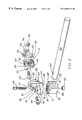
- FIG. 1 is a perspective view showing the coupling apparatus attached to a slide mount
- FIG. 2 is an exploded view showing the coupling apparatus of the present invention.
- FIG. 1 is a coupling apparatus 10 of the present invention.
- the coupling apparatus 10 has a base member 12 that is releasably connectable to a slide mount 14 for adjustably locating the coupling apparatus 10 along a predetermined path of travel.
- the base member 12 is adjustably connected to a midportion 16 of the coupling apparatus 10
- the midportion 16 is adjustably connected to an end member 18 of the coupling apparatus 10 .
- All three members 12 , 16 , 18 of the coupling apparatus 10 are preferably fabricated from cast aluminum to create a light weight, strong part that does not require machining.
- the present invention is not limited to cast aluminum, but rather, the coupling apparatus 10 may be fabricated from any material having the strength necessary to support the tooling assemblies and workpieces utilized in conjunction with the coupling apparatus 10 .
- the end member 18 is releasably connectable to a tooling rod or boom rod 20 that is typically utilized for carrying workpiece handling fixtures such as vacuum cups and/or clamps (not shown).
- the base member 12 has a substantially diamond shape configuration, as seen in FIGS. 1 and 2.
- An aperture 22 is provided at each end of the base member 12 , and the apertures 22 receive threaded fasteners 24 that each threadingly engage a nut 26 on the opposite side of the base member 12 .
- the nuts 26 are received and captured within a slot 28 provided in the slide mount 14 .
- the slot 28 has a substantially C-shaped configuration so that the nuts 26 remain captured within the slot 28 while providing the fasteners 24 access to the nuts 26 through the opening in the C-shaped slot 28 .
- the C-shaped slot 28 extends substantially linearly along a longitudinal axis.
- the base member 12 provides a contoured surface 30 on the front side 32 of the base member 12 .
- the contoured surface 30 is substantially circular and slightly raised from the front side 32 of the base member 12 .
- the contoured surface 30 has V-shaped teeth 34 formed therein which extend radially outward from a first centerline axis 36 of the contoured surface 30 .
- the V-shaped teeth 34 are circumferentially adjacent one another so as the V-shaped teeth 34 extend radially outward, the teeth 34 become wider to form a substantially concentric and uniform surface.
- the midportion 16 provides a first contoured surface 38 that matingly engages the contoured surface 30 of the base member 12 .
- the first contoured surface 38 of the midportion 16 is substantially similar to the contoured surface 30 of the base member 12 in that the first contoured surface 38 of the midportion 16 has a substantially circular surface having V-shaped teeth 40 extending radially outward from the first centerline axis 36 .
- the contoured surfaces 30 , 38 matingly engage by having the raised portions of the V-shaped teeth 34 , 40 matingly engage valleys or lower portions of the V-shaped teeth 40 , 34 of the opposing contoured surface 38 , 30 .
- Both the base member 12 and the midportion 16 provide apertures 42 , 43 , respectively, along the first centerline axis 36 for receiving a fastener 44 that extends through midportion 16 and base member 12 and is threadingly received by a threaded nut 46 that is captured within the slot 28 of the slide mount 14 .
- the fastener 44 and the nut 46 connect and secure the midportion 16 to the base member by ensuring that the contoured surfaces 30 , 38 maintain their engagement. This type of circular mating engagement without interference from neighboring parts allows for complete 360° orbital adjustment of the midportion 16 about the first centerline axis 36 relative to the base member 12 .
- the midportion 16 is also rotatably adjustable about a second centerline axis 47 with respect to the end member 18 by having a second contoured surface 48 of the midportion 16 matingly engage a contoured surface 50 of the end member 18 .
- the contoured surfaces 48 , 50 of the midportion 16 and the end member 18 are substantially similar to the contoured surfaces 30 , 38 provided between the base member 12 and the midportion 16 , respectively, in that the contoured surfaces 48 , 50 both provide substantially V-shaped teeth 49 , 51 that extend radially outward from the second centerline axis 47 .
- this type of circular mating engagement without interference from neighboring parts allows for complete 360° orbital adjustment of the midportion 16 about the second centerline axis 47 with respect to the end member 18 .
- the first contoured surface 38 and the second contoured surface 48 of the midportion 16 are integrally formed at one end of the contoured surfaces 38 , 48 and offset from one another at a substantially 90° angle.
- the backsides 53 of the contoured surfaces 38 , 48 are connected and supported by a substantially triangular webbing or structural support 52 that is integral with and extends between the backsides 53 of the contoured surfaces 38 , 48 .
- the structural support 52 has an aperture or cavity 55 which extends along the first centerline axis 36 and the second centerline axis 47 .
- the aperture or cavity 55 is in communication with the aperture 43 in the first contoured surface 38 of the midportion 16 and an aperture 57 in the second contoured surface 48 of the midportion 16 .
- the aperture 55 extends outward from the structural support 52 at the intersection of the first and second centerline axes 36 , 47 to form a substantially oval shaped opening 62 on an outer surface 64 of the structural support 52 .
- the substantially oval shaped opening 62 in the structural support 52 provides access to fasteners 44 , 54 along the first and second centerline axes 36 , 47 , respectively, and allows for the heads of the fasteners 44 , 54 to be housed within the cavity 55 of the structural support.
- a threaded nut 56 threadingly receives the fastener 54 and connects and secures the midportion 16 to the end member 18 by maintaining engagement between the contoured surfaces 48 , 50 of the midportion 16 and the end member 18 .
- the end member 18 has a substantially square body 66 having rounded corners with one of its sides being substantially arcuate.
- a top surface 68 of the end member 18 has the contoured surface 50 formed therein with an aperture 70 extending through the end member 18 along the second centerline axis 47 .
- a second aperture 58 substantially perpendicular to said second centerline axis 47 , is formed through a sidewall 72 of the end member 18 and is designed to receive an end of the boom rod 20 .
- the boom rod 20 has an aperture 60 extending therethrough for receiving the fastener 54 that releasably connects the midportion 16 to the end member 18 .
- the aperture 60 in the boom rod 20 receives the fastener 54 by having the centerline axis of the aperture 60 correspondingly align with the second centerline axis 47 .
- the coupling apparatus 10 may be adjusted along several axes of movement.
- the entire coupling apparatus 10 may be adjusted along the linear path of travel of the slide mount 14 by loosening the fasteners 24 , 44 from the nuts 26 , 46 , respectively.
- the coupling apparatus 10 is moved along the slot 28 of the slide mount 14 until the proper location is determined.
- the fasteners 24 , 44 are then threaded into their respective nuts 26 , 46 until the coupling apparatus 10 is secured to the slide mount 14 .
- the midportion 16 may be rotatably adjusted with respect to the base member 12 along the first centerline axis 36 by loosening the fastener 44 from the nut 46 .
- the fastener 44 must be loosened far enough to allow the opposing V-shaped teeth 34 , 40 of the contoured surfaces 30 , 38 , respectively, to rotate with respect to one another.
- the fastener 44 is threaded into the nut 46 until the midportion 16 is secured to the base member 12 and rotational movement of the midportion 16 with respect to the base member 12 is prohibited by maintaining engagement between the V-shaped teeth 34 , 40 of the contoured surfaces 30 , 38 .
- the fastener 54 is loosened from the nut 56 until the V-shaped teeth 49 , 51 of the contoured surfaces 48 , 50 may rotate with respect to one another without engaging peaks of the opposing V-shaped teeth 49 , 51 .
- the fastener 54 is threaded into the associated nut 56 until the end member 18 is secured to the midportion 16 and rotational movement of the midportion 16 and the end member 18 with respect to one another is prohibited by maintaining engagement between the V-shaped teeth 49 , 51 of the contoured surfaces 48 , 50 .
- the fastener 54 is unthreaded from the corresponding nut 56 and removed from the aperture 60 provided in the boom rod 20 .
- the boom rod 20 may then be removed and/or replaced with a different boom rod (not shown) wherein the fastener 54 would be reinserted through a similar corresponding aperture provided in the replacement boom rod.
- the fastener 54 would be threaded into the associated nut 56 until the boom rod was secure in the end member 18 , and the end member 18 was secured to the midportion 16 .
Abstract
Description
Claims (38)
Priority Applications (5)
| Application Number | Priority Date | Filing Date | Title |
|---|---|---|---|
| US09/458,519 US6409411B1 (en) | 1999-12-13 | 1999-12-13 | Modular tooling coupling apparatus |
| DE60002028T DE60002028T2 (en) | 1999-12-13 | 2000-12-11 | Modular tool coupling device |
| EP00311030A EP1108945B1 (en) | 1999-12-13 | 2000-12-11 | Modular tooling coupling apparatus |
| ES00311030T ES2212764T3 (en) | 1999-12-13 | 2000-12-11 | APPLIANCE APPLIANCE FOR APPLIANCE ELEMENTS |
| US09/736,862 US6619872B2 (en) | 1999-12-13 | 2000-12-13 | Modular tooling coupling apparatus |
Applications Claiming Priority (1)
| Application Number | Priority Date | Filing Date | Title |
|---|---|---|---|
| US09/458,519 US6409411B1 (en) | 1999-12-13 | 1999-12-13 | Modular tooling coupling apparatus |
Related Child Applications (1)
| Application Number | Title | Priority Date | Filing Date |
|---|---|---|---|
| US09/736,862 Continuation-In-Part US6619872B2 (en) | 1999-12-13 | 2000-12-13 | Modular tooling coupling apparatus |
Publications (1)
| Publication Number | Publication Date |
|---|---|
| US6409411B1 true US6409411B1 (en) | 2002-06-25 |
Family
ID=23821109
Family Applications (1)
| Application Number | Title | Priority Date | Filing Date |
|---|---|---|---|
| US09/458,519 Expired - Lifetime US6409411B1 (en) | 1999-12-13 | 1999-12-13 | Modular tooling coupling apparatus |
Country Status (1)
| Country | Link |
|---|---|
| US (1) | US6409411B1 (en) |
Cited By (28)
| Publication number | Priority date | Publication date | Assignee | Title |
|---|---|---|---|---|
| US6520574B1 (en) * | 2002-05-13 | 2003-02-18 | Hsi-Chin Huang | Beach chair with a sunshade |
| US6527466B1 (en) * | 2002-03-06 | 2003-03-04 | Thomas & Betts International, Inc. | Universal swivel mount |
| US6599050B1 (en) * | 1999-02-26 | 2003-07-29 | Sandvik Aktiebolag | Tool coupling |
| US6688479B2 (en) * | 2002-03-13 | 2004-02-10 | Shai-Wei Nei | U-shaped curtain rod with pivotable connecting arms |
| US6691965B1 (en) * | 2002-11-19 | 2004-02-17 | Macauto Industrial Co., Ltd. | Support device for a sunshade |
| US20060291951A1 (en) * | 2005-06-16 | 2006-12-28 | Norgren Automotive, Inc. | Multi-axis coupling apparatus for adjustably mounting modular tooling members |
| US20070006462A1 (en) * | 2005-07-06 | 2007-01-11 | Norgren Automotive, Inc. | Apparatus for accurately positioning and supporting modular tooling |
| US20070014115A1 (en) * | 2005-06-09 | 2007-01-18 | Robert Katz | Article Support Device |
| US20080226427A1 (en) * | 2005-07-06 | 2008-09-18 | Norgren Automotive, Inc. | Apparatus for accurately positioning and supporting modular tooling |
| US20090101765A1 (en) * | 2007-10-05 | 2009-04-23 | Panduit Corp. | Stackable Mount Assembly Including Indexing/Locking Features |
| US20130175264A1 (en) * | 2012-01-06 | 2013-07-11 | Wistron Corporation | Hinge Mechanism and Clamshell Device Thereof |
| US20130327912A1 (en) * | 2012-06-12 | 2013-12-12 | Yamaha Corporation | Device mounting apparatus |
| US20140270908A1 (en) * | 2013-03-15 | 2014-09-18 | Matthias Hiller | Adapter for Connecting an Auxiliary Handle to a Hand-Held Power Tool |
| DE102014209135B3 (en) * | 2014-05-14 | 2015-11-05 | Kennametal Inc. | Tool head and rotary tool with such |
| US20160290024A1 (en) * | 2015-04-06 | 2016-10-06 | Jerrold A. Gibson | Door Jam Stopper Device |
| US20160318193A1 (en) * | 2011-02-08 | 2016-11-03 | Norgren Automation Solutions, Llc | Modular Tooling Apparatus Having Serrated Teeth for Orbital and Linear Adjustment |
| CN107131186A (en) * | 2017-06-19 | 2017-09-05 | 滕巧娜 | A kind of tubing splices expanding unit |
| US20190085889A1 (en) * | 2017-09-19 | 2019-03-21 | SMR Patents S.à.r.l. | Locking ring, rear view device and vehicle |
| US10309584B2 (en) * | 2017-09-21 | 2019-06-04 | Ryan Johnson | Multi-directional pivot apparatus with locking mechanism |
| USD868855S1 (en) | 2018-03-13 | 2019-12-03 | Automation Services, Llc | Fixture bar clamp |
| US10689240B1 (en) | 2017-06-07 | 2020-06-23 | Cornelius, Inc. | Automated beverage dispensing machines |
| USD919167S1 (en) * | 2019-10-22 | 2021-05-11 | Nicor, Inc. | Adjustable transition mount |
| US11009065B2 (en) * | 2017-09-19 | 2021-05-18 | SMR Patents S.à.r.l. | Locking ring, rear view device and vehicle |
| CN114838041A (en) * | 2022-05-20 | 2022-08-02 | 安徽农业大学 | Connecting piece and exhibition room furniture |
| LU102627B1 (en) * | 2021-03-03 | 2022-09-05 | Herr Michael Wedig | Hollow-cylindrical component for forming a detachable connection with at least one other component and arrangement of such components |
| WO2022269344A1 (en) * | 2021-06-23 | 2022-12-29 | Railblaza Limited | Heavy duty adjustable mount system |
| US11879578B2 (en) * | 2021-12-28 | 2024-01-23 | Lear Corporation | Adjustable cable guide for a flat cable |
| CN114838041B (en) * | 2022-05-20 | 2024-05-03 | 安徽农业大学 | Connecting piece and exhibition hall furniture |
Citations (13)
| Publication number | Priority date | Publication date | Assignee | Title |
|---|---|---|---|---|
| US3205522A (en) * | 1963-08-28 | 1965-09-14 | Karl P Then | Universally adjustable tool holder |
| US3799599A (en) | 1973-01-26 | 1974-03-26 | B Jordan | Fluorescent lamp handling device |
| US3922481A (en) | 1973-03-12 | 1975-11-25 | Chance Co Ab | Open configuration midspan electrical conductor spacer |
| US4447170A (en) | 1982-03-02 | 1984-05-08 | Ralph Holmes | Connection assembly for use with an articulated linkage system |
| US4474328A (en) | 1982-09-29 | 1984-10-02 | Virginia Hale | Variable lift sprinkler unit |
| US4547092A (en) | 1984-02-21 | 1985-10-15 | Hamilton Industries | Accessory clamp for medical table |
| US4875651A (en) | 1988-12-06 | 1989-10-24 | Wergin Dennis D | Transducer mounting device |
| US4986016A (en) | 1986-12-10 | 1991-01-22 | Wichman William J | Folding display frame with offset hub configuration |
| US5520474A (en) | 1994-09-19 | 1996-05-28 | Liu; Yang-Ting | Adjustable coupling |
| US5538215A (en) | 1994-11-15 | 1996-07-23 | Midmark Corporation | Siderail socket |
| US5547305A (en) * | 1995-03-02 | 1996-08-20 | The Whitaker Corporation | Rapid, tool-less adjusting system for hotstick tooling |
| US5564852A (en) | 1995-03-29 | 1996-10-15 | Burndy Corporation | Adjustable hot stick adaptor |
| US6079682A (en) * | 1998-12-23 | 2000-06-27 | Nokia Mobile Phones Limited | Apparatus for mounting a mobile device on a support surface |
-
1999
- 1999-12-13 US US09/458,519 patent/US6409411B1/en not_active Expired - Lifetime
Patent Citations (13)
| Publication number | Priority date | Publication date | Assignee | Title |
|---|---|---|---|---|
| US3205522A (en) * | 1963-08-28 | 1965-09-14 | Karl P Then | Universally adjustable tool holder |
| US3799599A (en) | 1973-01-26 | 1974-03-26 | B Jordan | Fluorescent lamp handling device |
| US3922481A (en) | 1973-03-12 | 1975-11-25 | Chance Co Ab | Open configuration midspan electrical conductor spacer |
| US4447170A (en) | 1982-03-02 | 1984-05-08 | Ralph Holmes | Connection assembly for use with an articulated linkage system |
| US4474328A (en) | 1982-09-29 | 1984-10-02 | Virginia Hale | Variable lift sprinkler unit |
| US4547092A (en) | 1984-02-21 | 1985-10-15 | Hamilton Industries | Accessory clamp for medical table |
| US4986016A (en) | 1986-12-10 | 1991-01-22 | Wichman William J | Folding display frame with offset hub configuration |
| US4875651A (en) | 1988-12-06 | 1989-10-24 | Wergin Dennis D | Transducer mounting device |
| US5520474A (en) | 1994-09-19 | 1996-05-28 | Liu; Yang-Ting | Adjustable coupling |
| US5538215A (en) | 1994-11-15 | 1996-07-23 | Midmark Corporation | Siderail socket |
| US5547305A (en) * | 1995-03-02 | 1996-08-20 | The Whitaker Corporation | Rapid, tool-less adjusting system for hotstick tooling |
| US5564852A (en) | 1995-03-29 | 1996-10-15 | Burndy Corporation | Adjustable hot stick adaptor |
| US6079682A (en) * | 1998-12-23 | 2000-06-27 | Nokia Mobile Phones Limited | Apparatus for mounting a mobile device on a support surface |
Cited By (39)
| Publication number | Priority date | Publication date | Assignee | Title |
|---|---|---|---|---|
| US6599050B1 (en) * | 1999-02-26 | 2003-07-29 | Sandvik Aktiebolag | Tool coupling |
| US6527466B1 (en) * | 2002-03-06 | 2003-03-04 | Thomas & Betts International, Inc. | Universal swivel mount |
| US6688479B2 (en) * | 2002-03-13 | 2004-02-10 | Shai-Wei Nei | U-shaped curtain rod with pivotable connecting arms |
| US6520574B1 (en) * | 2002-05-13 | 2003-02-18 | Hsi-Chin Huang | Beach chair with a sunshade |
| US6691965B1 (en) * | 2002-11-19 | 2004-02-17 | Macauto Industrial Co., Ltd. | Support device for a sunshade |
| US7390110B2 (en) | 2005-06-09 | 2008-06-24 | Canlyte, Inc. | Article support device |
| US20080253138A1 (en) * | 2005-06-09 | 2008-10-16 | Canlyte Inc. | Article support device |
| US20070014115A1 (en) * | 2005-06-09 | 2007-01-18 | Robert Katz | Article Support Device |
| US7648253B2 (en) * | 2005-06-09 | 2010-01-19 | Canlyte Inc. | Article support device |
| US8162557B2 (en) | 2005-06-16 | 2012-04-24 | Norgren Automation Solutions, Llc | Multi-axis coupling apparatus for adjustably mounting modular tooling members |
| US20060291951A1 (en) * | 2005-06-16 | 2006-12-28 | Norgren Automotive, Inc. | Multi-axis coupling apparatus for adjustably mounting modular tooling members |
| US20080226427A1 (en) * | 2005-07-06 | 2008-09-18 | Norgren Automotive, Inc. | Apparatus for accurately positioning and supporting modular tooling |
| US8108978B2 (en) | 2005-07-06 | 2012-02-07 | Norgren Automation Solutions, Inc. | Apparatus for accurately positioning and supporting modular tooling |
| US20070006462A1 (en) * | 2005-07-06 | 2007-01-11 | Norgren Automotive, Inc. | Apparatus for accurately positioning and supporting modular tooling |
| US20090101765A1 (en) * | 2007-10-05 | 2009-04-23 | Panduit Corp. | Stackable Mount Assembly Including Indexing/Locking Features |
| US7770852B2 (en) * | 2007-10-05 | 2010-08-10 | Panduit Corp. | Stackable mount assembly including indexing/locking features |
| US20160318193A1 (en) * | 2011-02-08 | 2016-11-03 | Norgren Automation Solutions, Llc | Modular Tooling Apparatus Having Serrated Teeth for Orbital and Linear Adjustment |
| US20130175264A1 (en) * | 2012-01-06 | 2013-07-11 | Wistron Corporation | Hinge Mechanism and Clamshell Device Thereof |
| US8584320B2 (en) * | 2012-01-06 | 2013-11-19 | Wistron Corporation | Hinge mechanism and clamshell device thereof |
| US20130327912A1 (en) * | 2012-06-12 | 2013-12-12 | Yamaha Corporation | Device mounting apparatus |
| US20140270908A1 (en) * | 2013-03-15 | 2014-09-18 | Matthias Hiller | Adapter for Connecting an Auxiliary Handle to a Hand-Held Power Tool |
| US10160050B2 (en) | 2014-05-14 | 2018-12-25 | Kennametal, Inc. | Reaming head interface |
| DE102014209135B3 (en) * | 2014-05-14 | 2015-11-05 | Kennametal Inc. | Tool head and rotary tool with such |
| US20160290024A1 (en) * | 2015-04-06 | 2016-10-06 | Jerrold A. Gibson | Door Jam Stopper Device |
| US9903144B2 (en) * | 2015-04-06 | 2018-02-27 | Jerrold A. Gibson | Door jam stopper device |
| US10689240B1 (en) | 2017-06-07 | 2020-06-23 | Cornelius, Inc. | Automated beverage dispensing machines |
| US11440785B2 (en) | 2017-06-07 | 2022-09-13 | Marmon Foodservice Technologies, Inc. | Automated beverage dispensing machines |
| CN107131186A (en) * | 2017-06-19 | 2017-09-05 | 滕巧娜 | A kind of tubing splices expanding unit |
| US11009065B2 (en) * | 2017-09-19 | 2021-05-18 | SMR Patents S.à.r.l. | Locking ring, rear view device and vehicle |
| US10851831B2 (en) * | 2017-09-19 | 2020-12-01 | SMR Patents S.à.r.l. | Locking ring, rear view device and vehicle |
| US20190085889A1 (en) * | 2017-09-19 | 2019-03-21 | SMR Patents S.à.r.l. | Locking ring, rear view device and vehicle |
| US10309584B2 (en) * | 2017-09-21 | 2019-06-04 | Ryan Johnson | Multi-directional pivot apparatus with locking mechanism |
| USD868855S1 (en) | 2018-03-13 | 2019-12-03 | Automation Services, Llc | Fixture bar clamp |
| USD919167S1 (en) * | 2019-10-22 | 2021-05-11 | Nicor, Inc. | Adjustable transition mount |
| LU102627B1 (en) * | 2021-03-03 | 2022-09-05 | Herr Michael Wedig | Hollow-cylindrical component for forming a detachable connection with at least one other component and arrangement of such components |
| WO2022269344A1 (en) * | 2021-06-23 | 2022-12-29 | Railblaza Limited | Heavy duty adjustable mount system |
| US11879578B2 (en) * | 2021-12-28 | 2024-01-23 | Lear Corporation | Adjustable cable guide for a flat cable |
| CN114838041A (en) * | 2022-05-20 | 2022-08-02 | 安徽农业大学 | Connecting piece and exhibition room furniture |
| CN114838041B (en) * | 2022-05-20 | 2024-05-03 | 安徽农业大学 | Connecting piece and exhibition hall furniture |
Similar Documents
| Publication | Publication Date | Title |
|---|---|---|
| US6409411B1 (en) | Modular tooling coupling apparatus | |
| US6619872B2 (en) | Modular tooling coupling apparatus | |
| US8162557B2 (en) | Multi-axis coupling apparatus for adjustably mounting modular tooling members | |
| US5271651A (en) | Work holder support apparatus | |
| JP5883037B2 (en) | Modular tool arrangement with jagged teeth for rotational and linear adjustment | |
| US5909998A (en) | Tool mount for moving elements | |
| USRE36883E (en) | Holder for a flashlight | |
| US8108978B2 (en) | Apparatus for accurately positioning and supporting modular tooling | |
| US9534730B2 (en) | Multi-arm gimbal system | |
| EP1166955A3 (en) | System for attaching / detaching a workpiece to be machined on a jig | |
| US7588223B2 (en) | Clamp for clamping an object | |
| JP2014511282A5 (en) | ||
| US20230191545A1 (en) | Static flexible tooling system | |
| US5031867A (en) | Keyboard support apparatus | |
| KR20020059344A (en) | Modular gripper | |
| EP1518784A3 (en) | Automotive vehicle framing system | |
| US5836575A (en) | Wafer manual handpick station | |
| US4592541A (en) | Multiple workholding clamp assembly and attachment means | |
| US20080226427A1 (en) | Apparatus for accurately positioning and supporting modular tooling | |
| US7775495B2 (en) | Adapter assembly including telescoping links | |
| EP0479740B1 (en) | A device for supporting a robot on a support beam | |
| CN211332211U (en) | Fixture tool suitable for numerical control milling machine | |
| JP3553806B2 (en) | Parallel mechanism machine tool | |
| US6116845A (en) | Apparatus for supporting a workpiece for transfer | |
| US20090261218A1 (en) | Method of Manufacturing a Vacuum Cup Mount |
Legal Events
| Date | Code | Title | Description |
|---|---|---|---|
| AS | Assignment |
Owner name: ISI NORGREN, INC., MICHIGAN Free format text: ASSIGNMENT OF ASSIGNORS INTEREST;ASSIGNOR:CROREY, DAVID J.;REEL/FRAME:010550/0716 Effective date: 20000104 |
|
| AS | Assignment |
Owner name: ISI NORGREN, INC., MICHIGAN Free format text: RE-RECORD TO CORRECT THE STATE OF INCORPORATION OF THE RECEIVING PARTY, PREVIOUSLY RECORDED ON REEL 010550 FRAME 0716, ASSIGNOR CONFIRMS THE ASSIGNMENT OF THE ENTIRE INTEREST.;ASSIGNOR:CROREY, DAVID J.;REEL/FRAME:011046/0976 Effective date: 20000731 |
|
| AS | Assignment |
Owner name: NORGREN AUTOMOTIVE, INC., MICHIGAN Free format text: CHANGE OF NAME;ASSIGNOR:ISI NORGREN INC.;REEL/FRAME:011898/0927 Effective date: 20010530 |
|
| STCF | Information on status: patent grant |
Free format text: PATENTED CASE |
|
| FPAY | Fee payment |
Year of fee payment: 4 |
|
| FPAY | Fee payment |
Year of fee payment: 8 |
|
| FPAY | Fee payment |
Year of fee payment: 12 |