US6400703B1 - Device and method for generating and distributing coded symbols in a CDMA communication system - Google Patents

Device and method for generating and distributing coded symbols in a CDMA communication system Download PDF

Info

Publication number
US6400703B1
US6400703B1 US09/324,423 US32442399A US6400703B1 US 6400703 B1 US6400703 B1 US 6400703B1 US 32442399 A US32442399 A US 32442399A US 6400703 B1 US6400703 B1 US 6400703B1
Authority
US
United States
Prior art keywords
symbol
symbols
channel
generate
input data
Prior art date
Legal status (The legal status is an assumption and is not a legal conclusion. Google has not performed a legal analysis and makes no representation as to the accuracy of the status listed.)
Expired - Lifetime
Application number
US09/324,423
Inventor
Chang-soo Park
Jun-jin Kong
Hee-Won Kang
Jae-Yoel Kim
Jong-Seon No
Kyeong-Cheol Yang
Current Assignee (The listed assignees may be inaccurate. Google has not performed a legal analysis and makes no representation or warranty as to the accuracy of the list.)
Samsung Electronics Co Ltd
Original Assignee
Samsung Electronics Co Ltd
Priority date (The priority date is an assumption and is not a legal conclusion. Google has not performed a legal analysis and makes no representation as to the accuracy of the date listed.)
Filing date
Publication date
Application filed by Samsung Electronics Co Ltd filed Critical Samsung Electronics Co Ltd
Assigned to SAMSUNG ELECTRONICS CO., LTD. reassignment SAMSUNG ELECTRONICS CO., LTD. ASSIGNMENT OF ASSIGNORS INTEREST (SEE DOCUMENT FOR DETAILS). Assignors: KANG, HEE-WON, KIM, JAE-YOEL, KONG, JUN-JIN, NO, JONG-SEON, PARK, CHANG-SOO, YANG, KYEONG-CHEOL
Application granted granted Critical
Publication of US6400703B1 publication Critical patent/US6400703B1/en
Anticipated expiration legal-status Critical
Expired - Lifetime legal-status Critical Current

Links

Images

Classifications

    • HELECTRICITY
    • H04ELECTRIC COMMUNICATION TECHNIQUE
    • H04BTRANSMISSION
    • H04B1/00Details of transmission systems, not covered by a single one of groups H04B3/00 - H04B13/00; Details of transmission systems not characterised by the medium used for transmission
    • H04B1/69Spread spectrum techniques
    • H04B1/707Spread spectrum techniques using direct sequence modulation
    • HELECTRICITY
    • H04ELECTRIC COMMUNICATION TECHNIQUE
    • H04LTRANSMISSION OF DIGITAL INFORMATION, e.g. TELEGRAPHIC COMMUNICATION
    • H04L1/00Arrangements for detecting or preventing errors in the information received
    • H04L1/004Arrangements for detecting or preventing errors in the information received by using forward error control
    • H04L1/0041Arrangements at the transmitter end
    • HELECTRICITY
    • H03ELECTRONIC CIRCUITRY
    • H03MCODING; DECODING; CODE CONVERSION IN GENERAL
    • H03M13/00Coding, decoding or code conversion, for error detection or error correction; Coding theory basic assumptions; Coding bounds; Error probability evaluation methods; Channel models; Simulation or testing of codes
    • H03M13/03Error detection or forward error correction by redundancy in data representation, i.e. code words containing more digits than the source words
    • H03M13/23Error detection or forward error correction by redundancy in data representation, i.e. code words containing more digits than the source words using convolutional codes, e.g. unit memory codes
    • HELECTRICITY
    • H03ELECTRONIC CIRCUITRY
    • H03MCODING; DECODING; CODE CONVERSION IN GENERAL
    • H03M13/00Coding, decoding or code conversion, for error detection or error correction; Coding theory basic assumptions; Coding bounds; Error probability evaluation methods; Channel models; Simulation or testing of codes
    • H03M13/63Joint error correction and other techniques
    • H03M13/635Error control coding in combination with rate matching
    • HELECTRICITY
    • H04ELECTRIC COMMUNICATION TECHNIQUE
    • H04JMULTIPLEX COMMUNICATION
    • H04J13/00Code division multiplex systems
    • H04J13/10Code generation
    • HELECTRICITY
    • H04ELECTRIC COMMUNICATION TECHNIQUE
    • H04JMULTIPLEX COMMUNICATION
    • H04J13/00Code division multiplex systems
    • H04J13/16Code allocation
    • HELECTRICITY
    • H04ELECTRIC COMMUNICATION TECHNIQUE
    • H04LTRANSMISSION OF DIGITAL INFORMATION, e.g. TELEGRAPHIC COMMUNICATION
    • H04L1/00Arrangements for detecting or preventing errors in the information received
    • H04L1/004Arrangements for detecting or preventing errors in the information received by using forward error control
    • H04L1/0056Systems characterized by the type of code used
    • H04L1/0059Convolutional codes
    • HELECTRICITY
    • H04ELECTRIC COMMUNICATION TECHNIQUE
    • H04LTRANSMISSION OF DIGITAL INFORMATION, e.g. TELEGRAPHIC COMMUNICATION
    • H04L1/00Arrangements for detecting or preventing errors in the information received
    • H04L1/004Arrangements for detecting or preventing errors in the information received by using forward error control
    • H04L1/0056Systems characterized by the type of code used
    • H04L1/0067Rate matching
    • H04L1/0068Rate matching by puncturing
    • HELECTRICITY
    • H04ELECTRIC COMMUNICATION TECHNIQUE
    • H04LTRANSMISSION OF DIGITAL INFORMATION, e.g. TELEGRAPHIC COMMUNICATION
    • H04L1/00Arrangements for detecting or preventing errors in the information received
    • H04L1/004Arrangements for detecting or preventing errors in the information received by using forward error control
    • H04L1/0056Systems characterized by the type of code used
    • H04L1/0071Use of interleaving

Definitions

  • the present invention relates generally to a CDMA communication system, and in particular, to a device and method for generating and distributing coded symbols capable of preventing degradation in channel performance during data transmission.
  • CDMA communication systems are implemented according to the IS-95 standard.
  • CDMA communication technology With an increase in the sophistication of CDMA communication technology and a decrease in usage costs, there has been an exponential growth in the number of subscribers of CDMA communication services. Accordingly, many methods have been proposed for meeting subscribers' ever-increasing demands for high quality CDMA service. For example, several methods for improving a forward link structure in the CDMA communication system have been proposed.
  • FIG. 1 A forward link structure for a multicarrier CDMA communication system is illustrated in FIG. 1 .
  • a channel encoder 10 encodes input data, and a rate matcher 20 repeats and punctures symbols outputted from the channel encoder 10 .
  • the data input to the channel encoder 10 has a variable bit rate.
  • the rate matcher 20 repeats and punctures the coded data bits (i.e., symbols) outputted from the channel encoder 10 to match symbol rates for the data having the variable bit rate.
  • a channel interleaver 30 interleaves an output of the rate matcher 20 .
  • a block interleaver is typically used for the interleaver 30 .
  • a long code generator 91 generates a long code which is identical to that used by the subscriber.
  • the long code is a unique identification code for the subscriber. Thus, different long codes are assigned to the respective subscribers.
  • a decimator 92 decimates the long code to match a rate of the long code to a rate of the symbols outputted from the interleaver 30 .
  • An adder 93 adds an output of the channel interleaver 30 and an output of the decimator 92 .
  • An exclusive OR gate is typically used for the adder 93 .
  • a demultiplexer 40 sequentially multiplexes data outputted from the adder 93 to multiple carriers A, B and C.
  • First to third binary-to-four level converters 51 - 53 convert signal levels of binary data outputted from the demultiplexer 40 by converting input data of “0” to “+1” and input data of “1” to “ ⁇ 1”.
  • First to third orthogonal modulators 61 - 63 encode data outputted from the first to third level converts 51 - 53 with corresponding Walsh codes, respectively.
  • the Walsh codes have a length of 256 bits.
  • First to third spreaders 71 - 73 spread outputs of the first to third orthogonal modulators 61 - 63 , respectively.
  • QPSK Quadrature Phase Shift Keying
  • First to third attenuators (or gain controllers) 81 - 83 control gains of the spread signals outputted from the first to third spreaders 71 - 73 according to corresponding attenuation signals GA-GC, respectively.
  • the signals outputted from the first to third attenuators 81 - 83 become different carriers A, B and C.
  • the multicarrier CDMA communication system of FIG. 1 can be modified to a single carrier CDMA communication system by removing the demultiplexer 40 and using only one level converter, one orthogonal modulator, one spreader and one attenuator.
  • FIG. 2 is a detailed diagram illustrating the channel encoder 10 , the rate matcher 20 and the channel interleaver 30 .
  • data of a first rate is composed of 172 bits (fall rate) per 20 ms frame
  • data of a second rate is composed of 80 bits (1 ⁇ 2 rate) per 20 ms frame
  • data of a third rate is composed of 40 bits (1 ⁇ 4 rate) per 20 ms frame
  • data of a fourth rate is composed of 16 bits (1 ⁇ 8 rate) per 20 ms frame.
  • First to fourth CRC generators 111 - 114 generate CRC bits corresponding to the respective input data having different rates and add the generated CRC bits to the input data. Specifically, 12-bit CRC is added to the 172-bit data of the first rate; 8-bit CRC is added to the 80-bit data of the second rate; 6-bit CRC is added to the 40-bit data of the third rate; and 6-bit CRC is added to the 16-bit data of the fourth rate.
  • First to fourth tail bit generators 121 - 124 add 8 tail bits to the CRC-added data, respectively. Therefore, the first tail bit generator 121 outputs 192 bits; the second tail bit generator 122 outputs 96 bits; the third tail bit generator 123 outputs 54 bits; and the fourth tail bit generator 124 outputs 30 bits.
  • First to fourth encoders 11 - 14 encode data output from the first to fourth tail bit generators 121 - 124 , respectively.
  • the first encoder 11 encodes the 192-bit data output from the first tail bit generator 121 into 576 symbols of full rate; the second encoder 12 encodes the 96-bit data output from the second tail bit generator 122 into 288 symbols of 1 ⁇ 2 rate; the third encoder 13 encodes the 54-bit data output from the third tail bit generator 123 into 162 symbols of about 1 ⁇ 4 rate; and the fourth encoder 14 encodes the 30-bit data output from the fourth tail bit generator 124 into 90 symbols of about 1 ⁇ 8 rate.
  • the rate matcher 20 includes repeaters 22 - 24 and symbol deletion devices 27 - 28 .
  • the repeaters 22 - 24 repeat symbols outputted from the second to fourth encoders 12 - 14 according to predetermined times to increase output symbol rates thereof to the fall rate.
  • the symbol deletion devices 27 and 28 delete symbols outputted from the repeaters 23 and 24 which exceed the symbols of the full rate in number. Since the second encoder 12 outputs 288 symbols which is 1 ⁇ 2 the 576 symbols outputted from the first encoder 11 , the second repeater 22 repeats the received 288 symbols two times to output 576 symbols.
  • the third encoder 13 outputs 162 symbols which is about 1 ⁇ 4 the 576 symbols outputted from the first encoder 11 , the third repeater 23 repeats the received 162 symbols four times to output 648 symbols which exceeds the 576 symbols of full rate in number.
  • the symbol deletion device 27 deletes every ninth symbol to output 576 symbols of full rate.
  • the fourth encoder 14 outputs 90 symbols which is about 1 ⁇ 8 the 576 symbols output from the first encoder 11 , the fourth repeater 24 repeats the received 90 symbols eight times to output 720 symbols which exceeds the 576 symbols of full rate in number.
  • the symbol deletion device 28 deletes every fifth symbol to output 576 symbols of full rate.
  • First to fourth channel interleavers 31 - 34 interleave the symbols of full rate outputted from the first encoder 11 , the second repeater 22 , the symbol deletion device 27 and the symbol deletion device 28 , respectively.
  • Forward Error Correction is used to maintain a sufficiently low Bit Error Rate (BER) of a mobile station for a channel having a low signal-to-noise ratio (SNR) by providing a channel coding gain.
  • the forward link for the multicarrier communication system can share the same frequency band with the forward link for the IS-95 system in an overlay method.
  • the overlay method provides the following problems.
  • FIG. 3 illustrates transmission power levels, by the respective bands, of base stations for the IS-95 system and the multicarrier system.
  • the transmission power or channel capacity is shared between the IS-95 base station and the multicarrier base station at the same frequency band.
  • the transmission power is first allocated for the IS-95 channel which mainly supports a voice service and then, the maximum transmission power permissible to the respective carriers for the multicarrier CDMA system is determined.
  • FIG. 3 illustrates the state where the IS-95 base station and the multicarrier base station allocate substantially equal transmission power at the respective 1.25 MHz frequency bands.
  • FIGS. 4 and 5 illustrate situations where the transmission power allocated for the multicarrier base station decreases at some carriers, as the transmission power allocated for the IS-95 base station increases rapidly at the corresponding frequency bands due to an increase in the number of IS-95 subscribers.
  • sufficient transmission power cannot be allocated for one or more of the multiple carriers so the SNRs are different according to the carriers at the receiver. Accordingly, a signal received at a carrier having the low SNR increases in a bit error rate (BER).
  • BER bit error rate
  • the overlay method may cause a reduction in capacity of the multicarrier system and an increase in interference among the IS-95 subscribers.
  • the respective carriers may have independent transmission powers as illustrated in FIGS. 4 and 5.
  • FIG. 5 shows the power distribution being worse than the case where the channel encoder is not used.
  • one or two of the three coded bits (i.e., symbols) for an input data bit may not be transmitted, causing a degradation in system performance.
  • an object of the present invention to provide a channel encoding device and method capable of generating coded data exhibiting a good channel coding performance in a CDMA communication system.
  • It is still another object of the present invention to provide an R 1/6 convolutional encoding device and method capable of increasing channel performance of a channel transmitter in a CDMA communication system.
  • the communication system includes a channel encoder for encoding data, a channel controller for generating a control signal for transmitting channel coded symbols for performing decoding using data received via at least one carrier, and a symbol distributer for assigning the channel coded symbols to at least two carriers.
  • a channel encoding device having a plurality of delays for delaying an input data bit to generate first to eight delayed data bits; a first operator for exclusively Oring the input data bit and the third, fifth, sixth, seventh and eighth delayed data bits to generate a first sysmbol; a second operator for exclusively Oring the input data bit and the first, second, third, fifth, sixth and eighth delayed data bits to generate a second symbol; a third operator for exclusively Oring the input data bit and the second, third, fifth and eighth delayed data bits to generate a third symbol; a fourth operator for exclusively Oring the input data bit and the first, fourth, fifth, sixth, seventh and eighth delayed data bits to generate a fourth symbol; a fifth operator for exclusively Oring the input data bit and the first, fourth, sixth and eighth delayed data bitss to generate a fifth symbol; and a sixth operator for exclusively Oring the input data bit and the first, second, fourth, sixth, seventh and eighth delayed data bits to generate a sixth symbol.
  • FIG. 1 is a block diagram of a forward link structure for a conventional multicarrier CDMA communication system
  • FIG. 2 is a block diagram illustrating a fundamental channel structure for the forward link structure of FIG. 1;
  • FIG. 3 is a diagram illustrating transmission power distribution of IS-95 channel bands and multicarrier channel bands where the multicarrier channel bands are overlaid on the IS-95 channel bands at the same frequency bands in the CDMA system of FIG. 1;
  • FIG. 4 is a diagram illustrating a state where the transmission power of one multiple carrier is decreased when a transmission power for a corresponding IS-95 channel is increased, due to a limitation in transmission power or transmission capacity in the CDMA system of FIG. 1;
  • FIG. 5 is a diagram illustrating a state where the transmission power of two multiple carriers decreases when transmission power for corresponding IS-95 channels are increased, due to a limitation in transmission power or transmission capacity in the CDMA system of FIG. 1;
  • FIG. 8 illustrates the symbol distributer of FIG. 6
  • FIG. 9 illustrates block diagrams of a transmission scheme for a forward link using the channel encoder and the symbol distributer according to the present invention.
  • symbol refers to a coded data bit outputted from an encoder.
  • the multicarrier communication system is a three-carrier CDMA communication system. It is contemplated that the present invention can be embodied in other types of communication systems, such as Time Division Multiple Access (TDMA).
  • TDMA Time Division Multiple Access
  • the present invention provides a device and method for improving system performance in a communication system supporting both the IS-95 system and the multicarrier system, wherein transmission signals of the two different systems are overlaid at the same frequence bands.
  • the coded symbols are distributed such that performance degradation is minimized during decoding of the damaged symbols, and then the distributed coded bits are assigned to the respective carriers.
  • the coded symbols are distributed such that performance degradation is minimized during decoding of the damaged symbols, and then the distributed coded bits are assigned to the respective carriers.
  • FIG. 6 illustrates a convolutional encoder 601 and a symbol distributer 602 according to an embodiment of the present invention.
  • the convolutional encoder 601 encodes one input data bit into six symbols which are allocated to three carriers A, B and C.
  • the symbol distributer 602 uniformly distributes the six input bits to the three carriers by two bits.
  • the symbol distributer 602 distributes the symbols outputted from the convolutional encoder 601 , taking into consideration how many carriers are damaged out of the three carriers. By using this symbol distribution method, even though one or two of the three carriers are damaged, performance degradation in channel decoding is minimized.
  • a bit error rate (BER) value after channel decoding depends primarily on the number of damaged portions of the symbols which were coded by a channel encoder. Even though the coded symbols are damaged, the symbols located at portions which are least likely to degrade system performance are uniformly distributed to the carriers. Accordingly, even though the symbols for a certain channel are all damaged, an increase in the BER value can be minimized after channel decoding by distributing the non-damaged symbols (or the damaged symbols which are the least likely to degrade system performance) to the carriers.
  • the symbols outputted from a constituent encoder in the channel encoder are distributed to the carriers; during decoding, a constituent decoder in a channel decoder is selected such that the BER can be low, even though the symbols for a certain carrier are all damaged.
  • a performance of a convolutional code can be predicted using a BER upper limit formula, which is determined by a transfer function.
  • a transfer function of a convolutional code is T(D,I)
  • I 1 11D 18 +32D 20 +O(D 21 ).
  • d 12 in a first term means d (467,543) and hereinafter is used to provide the same meaning.
  • the first and eighth codes are superior in performance to the IS-95 codes
  • the third, fourth, fifth and sixth codes are similar in performance to the IS-95 codes
  • the second and seventh codes are inferior in performance to the IS-95 codes. Therefore, it is preferable to use the eighth (or first) code.
  • AWGN Additional White Gaussian Noise
  • FIGS. 11-13 are all performed in the AWGN environment.
  • the two symbol deleting matrixes shown below are generated.
  • “0” means the case where a carrier to which the corresponding symbol is provided is damaged
  • “1” means the case where the carrier to which the corresponding symbol is provided is not damaged. This means that the symbols corresponding to “0” are all allocated to a certain carrier which is damaged during transmission.
  • one of the following various patterns of the symbol deleting matrix is selected which minimizes performance degradation even though one carrier is damaged, and the symbol distributer 602 provides the symbols to the respective carriers using the selected pattern.
  • the following symbol deleting matrixes are used for finding a pattern to be used by the symbol distributer 602 to correctly allocate the symbols to the respective carriers.
  • D 1 [ 0 1 1 1 0 1 1 1 0 ]
  • D 2 [ 1 1 0 1 0 1 0 1 1 ]
  • an m-sequence having an 8-bit length is generated over a two-stage GF( 3 ) using an m-sequence.
  • a sequence ⁇ 1,2,0,2,2,1,0,1,2 ⁇ is generated and then, the following symbol deleting matrix D 3 is generated using the sequence.
  • D 3 [ 1 1 0 1 1 1 0 1 1 0 1 1 0 1 1 1 1 0 1 0 1 1 0 1 0 1 1 1 0 0 0 1 1 1 0 ]
  • a sequence ⁇ 2,1,0,1,1,0,1,2,1,0,0,0,2,1,2 ⁇ is obtained by generating 15 random numbers over GF( 3 ) using a random number, and the following symbol deleting matrix D 6 using the above sequence.
  • D 6 [ 1 1 0 1 1 0 1 1 1 0 0 0 1 1 1 1 0 1 0 0 1 0 1 0 1 0 1 0 1 0 1 1 1 1 1 1 1 0 1 0 1 0 1 1 1 1 1 1 0 1 1 0 1 0 ]
  • D 7 [ 0 1 1 1 1 1 1 1 0 1 1 1 1 0 1 0 1 1 1 0 1 1 1 0 0 0 1 1 1 1 0 1 0 0 1 0 1 0 1 0 1 0 1 0 1 0 1 0 1 0 1 ]
  • D 8 [ 1 0 1 0 0 1 0 1 0 1 0 1 0 1 1 1 1 1 0 1 0 1 1 1 1 1 0 1 0 1 1 1 1 0 1 0 1 1 1 0 0 0 1 1 ]
  • FIG. 6 there is shown the convolutional encoder 601 and the symbol distributer 602 according to an embodiment of the present invention.
  • delays 711 -A to 711 -H delay the input data bits sequentially.
  • exclusive OR gates 721 -A to 721 -F output coded symbols.
  • the coded symbols of FIG. 7 are provided to the symbol distributer 602 having the structure as shown by FIG. 8 .
  • the symbol distributer 602 is implemented by switches 811 -A and 811 -B.
  • switches 811 -A and 811 -B when a symbol rate of a clock for controlling the switches 811 -A and 811 -B is over six times a symbol rate of the symbol distributer 602 , the symbols can be distributed without symbol loss. That is, the switch 811 -A sequentially receives input symbols g 1 , g 2 , g 3 , g 4 , g 5 , g 6 , g 1 , g 2 , g 3 , . . . , and the switch 811 -B distributes the input symbols to output nodes c 1 , c 2 , c 3 , c 4 , c 5 and c 6 .
  • FIG. 9 illustrates transmission schemes using the channel encoder 601 and the symbol distributer 602 of FIG. 6 .
  • First to fourth CRC generators 911 - 914 add CRC data in a specified number of bits to input data. Specifically, 12-bit CRC is added to the 172-bit data of the first rate; 8-bit CRC is added to the 80-bit data of the second rate; 6-bit CRC is added to the 40-bit data of the third rate; and 6-bit CRC is added to the 16-bit data of the fourth rate.
  • First to fourth tail bit generators 921 - 924 add 8 tail bits to the CRC-added data. Therefore, the first tail bit generator 921 outputs 192 bits; the second tail bit generator 922 outputs 96 bits; the third tail bit generator 923 outputs 54 bits; and the fourth tail bit generator 924 outputs 30 bits.
  • First to fourth encoders 931 - 934 encode data output from the first to fourth tail bit generators 921 - 924 , respectively.
  • the first encoder 931 encodes the 192-bit data output from the first tail bit generator 921 into 1152 symbols of fall rate; the second encoder 932 encodes the 96-bit data output from the second tail bit generator 922 into 576 symbols of 1 ⁇ 2 rate; the third encoder 933 encodes the 54-bit data output from the third tail bit generator 923 into 324 symbols of about 1 ⁇ 4 rate; and the fourth encoder 934 encodes the 30-bit data output from the fourth tail bit generator 924 into 180 symbols of about 1 ⁇ 8 rate.
  • First to fourth symbol distributers 941 - 944 distribute the symbols output from the encoders 931 - 934 , respectively.
  • a channel controller (not shown) generates control signals for distributing the channel-coded bits such that performance degradation is minimized during decoding of received damaged bits, when the coded symbols being transmitted are overlaid on the symbols of a different system at the same frequency band.
  • the symbol distributers 941 - 944 then assign the symbols outputted from the encoders 931 - 934 to the corresponding carriers according to the control signals.
  • Rate matchers 951 - 953 each include a symbol repeater and a symbol deletion device.
  • the rate matchers 951 - 953 match rates of the symbols outputted from the corresponding symbol distributers 942 - 944 to a rate of the symbols outputted from the symbol distributer 941 .
  • First to fourth channel interleavers 961 - 964 interleave the symbols outputted from the symbol distributer 941 and the rate matchers 951 - 953 , respectively.
  • the symbol distributers 941 - 944 of FIG. 9 can be removed.
  • the respective carriers have limited transmission powers according to the loading in the frequency bands of the IS-95 system, which results in loss of data received at one or more carrier frequency bands.
  • the generator polynomials for the channel encoder and a symbol distribution method it is possible to provide a high coding gain against the data loss due to the carrier loss, thereby preventing degradation of the BER.

Abstract

A device and method for generating and distributing convolutional codes such that performance degradation due to a bad link environment may be minimized during channel decoding in a CDMA communication system. The convolutional encoder encodes transmission data at a coding rate of R=1/6 and can be used for a channel encoder. Such a channel encoder can be used in both a DS-CDMA communication system and a multicarrier CDMA communication system. When the channel encoder is used in the multicarrier CDMA communication system, the symbols outputted from multiple constituent encoders for the channel encoder are distributed to multiple carrier channels according to a predetermined rule, and the constituent encoders for the channel encoder can minimize the performance degradation of the overall channel encoder even though an output of a particular constituent encoder is completely off at the transmission channel.

Description

PRIORITY
This application claims priority to an application entitled “Device and Method for Generating and Distributing Coded Symbols in CDMA Communication System” filed in the Korean Industrial Property Office on May 30, 1998 and assigned Serial No. 98-20141, the contents of which are hereby incorporated by reference.
BACKGROUND OF THE INVENTION
1. Field of the Invention
The present invention relates generally to a CDMA communication system, and in particular, to a device and method for generating and distributing coded symbols capable of preventing degradation in channel performance during data transmission.
2. Description of the Related Art
Code Division Multiple Access (CDMA) communication systems are implemented according to the IS-95 standard. With an increase in the sophistication of CDMA communication technology and a decrease in usage costs, there has been an exponential growth in the number of subscribers of CDMA communication services. Accordingly, many methods have been proposed for meeting subscribers' ever-increasing demands for high quality CDMA service. For example, several methods for improving a forward link structure in the CDMA communication system have been proposed.
One such method for improving the forward link structure, especially a forward link fundamental channel designed for a third generation multicarrier CDMA system, was proposed in the TIA/EIA TR45.5 conference and approved on May 15, 1998 by the Telecommunications Industry Association (TIA). A forward link structure for a multicarrier CDMA communication system is illustrated in FIG. 1.
With reference to FIG. 1, a channel encoder 10 encodes input data, and a rate matcher 20 repeats and punctures symbols outputted from the channel encoder 10. Here, the data input to the channel encoder 10 has a variable bit rate. The rate matcher 20 repeats and punctures the coded data bits (i.e., symbols) outputted from the channel encoder 10 to match symbol rates for the data having the variable bit rate. A channel interleaver 30 interleaves an output of the rate matcher 20. A block interleaver is typically used for the interleaver 30.
A long code generator 91 generates a long code which is identical to that used by the subscriber. The long code is a unique identification code for the subscriber. Thus, different long codes are assigned to the respective subscribers. A decimator 92 decimates the long code to match a rate of the long code to a rate of the symbols outputted from the interleaver 30. An adder 93 adds an output of the channel interleaver 30 and an output of the decimator 92. An exclusive OR gate is typically used for the adder 93.
A demultiplexer 40 sequentially multiplexes data outputted from the adder 93 to multiple carriers A, B and C. First to third binary-to-four level converters 51-53 convert signal levels of binary data outputted from the demultiplexer 40 by converting input data of “0” to “+1” and input data of “1” to “−1”. First to third orthogonal modulators 61-63 encode data outputted from the first to third level converts 51-53 with corresponding Walsh codes, respectively. Here, the Walsh codes have a length of 256 bits. First to third spreaders 71-73 spread outputs of the first to third orthogonal modulators 61-63, respectively. Here, QPSK (Quadrature Phase Shift Keying) spreaders can be used for the spreaders 71-73. First to third attenuators (or gain controllers) 81-83 control gains of the spread signals outputted from the first to third spreaders 71-73 according to corresponding attenuation signals GA-GC, respectively. Here, the signals outputted from the first to third attenuators 81-83 become different carriers A, B and C.
In the forward link structure of FIG. 1, the channel encoder 10, having a coding rate of R=1/3, encodes the input data into 3 coded data bits (i.e., code words or symbols) per bit. Such coded data bits are demultiplexed to the three carriers A, B and C after rate matching and channel interleaving. The multicarrier CDMA communication system of FIG. 1 can be modified to a single carrier CDMA communication system by removing the demultiplexer 40 and using only one level converter, one orthogonal modulator, one spreader and one attenuator.
FIG. 2 is a detailed diagram illustrating the channel encoder 10, the rate matcher 20 and the channel interleaver 30. In FIG. 2, data of a first rate is composed of 172 bits (fall rate) per 20 ms frame; data of a second rate is composed of 80 bits (½ rate) per 20 ms frame; data of a third rate is composed of 40 bits (¼ rate) per 20 ms frame; and data of a fourth rate is composed of 16 bits (⅛ rate) per 20 ms frame.
First to fourth CRC generators 111-114 generate CRC bits corresponding to the respective input data having different rates and add the generated CRC bits to the input data. Specifically, 12-bit CRC is added to the 172-bit data of the first rate; 8-bit CRC is added to the 80-bit data of the second rate; 6-bit CRC is added to the 40-bit data of the third rate; and 6-bit CRC is added to the 16-bit data of the fourth rate. First to fourth tail bit generators 121-124 add 8 tail bits to the CRC-added data, respectively. Therefore, the first tail bit generator 121 outputs 192 bits; the second tail bit generator 122 outputs 96 bits; the third tail bit generator 123 outputs 54 bits; and the fourth tail bit generator 124 outputs 30 bits.
First to fourth encoders 11-14 encode data output from the first to fourth tail bit generators 121-124, respectively. A convolutional encoder having a constraint length of K=9 and a coding rate of R=1/3 can be used for the encoders 11-14. In this case, the first encoder 11 encodes the 192-bit data output from the first tail bit generator 121 into 576 symbols of full rate; the second encoder 12 encodes the 96-bit data output from the second tail bit generator 122 into 288 symbols of ½ rate; the third encoder 13 encodes the 54-bit data output from the third tail bit generator 123 into 162 symbols of about ¼ rate; and the fourth encoder 14 encodes the 30-bit data output from the fourth tail bit generator 124 into 90 symbols of about ⅛ rate.
The rate matcher 20 includes repeaters 22-24 and symbol deletion devices 27-28. The repeaters 22-24 repeat symbols outputted from the second to fourth encoders 12-14 according to predetermined times to increase output symbol rates thereof to the fall rate. The symbol deletion devices 27 and 28 delete symbols outputted from the repeaters 23 and 24 which exceed the symbols of the full rate in number. Since the second encoder 12 outputs 288 symbols which is ½ the 576 symbols outputted from the first encoder 11, the second repeater 22 repeats the received 288 symbols two times to output 576 symbols. Further, since the third encoder 13 outputs 162 symbols which is about ¼ the 576 symbols outputted from the first encoder 11 , the third repeater 23 repeats the received 162 symbols four times to output 648 symbols which exceeds the 576 symbols of full rate in number. To match the symbol rate to the full rate, the symbol deletion device 27 deletes every ninth symbol to output 576 symbols of full rate. In addition, since the fourth encoder 14 outputs 90 symbols which is about ⅛ the 576 symbols output from the first encoder 11, the fourth repeater 24 repeats the received 90 symbols eight times to output 720 symbols which exceeds the 576 symbols of full rate in number. To match the symbol rate to the full rate, the symbol deletion device 28 deletes every fifth symbol to output 576 symbols of full rate.
First to fourth channel interleavers 31-34 interleave the symbols of full rate outputted from the first encoder 11, the second repeater 22, the symbol deletion device 27 and the symbol deletion device 28, respectively. Forward Error Correction (FEC) is used to maintain a sufficiently low Bit Error Rate (BER) of a mobile station for a channel having a low signal-to-noise ratio (SNR) by providing a channel coding gain. The forward link for the multicarrier communication system can share the same frequency band with the forward link for the IS-95 system in an overlay method. However, the overlay method provides the following problems.
In the overlay method, three forward link carriers for the multicarrier system are overlaid on three 1.25 MHz bands used in the IS-95 CDMA system. FIG. 3 illustrates transmission power levels, by the respective bands, of base stations for the IS-95 system and the multicarrier system. In the overlay method, since the frequency bands for the multicarrier system are overlaid on the frequency bands for the IS-95 system, the transmission power or channel capacity is shared between the IS-95 base station and the multicarrier base station at the same frequency band. In the case where the transmission power is shared between the two systems, the transmission power is first allocated for the IS-95 channel which mainly supports a voice service and then, the maximum transmission power permissible to the respective carriers for the multicarrier CDMA system is determined. Here, the maximum transmission power cannot exceed a predetermine power level, because the base station has a limited transmission power. Further, when the base station transmits data to many subscribers, interference among the subscribers increases resulting in an increase in noise. FIG. 3 illustrates the state where the IS-95 base station and the multicarrier base station allocate substantially equal transmission power at the respective 1.25 MHz frequency bands.
However, the IS-95 channels of 1.25 MHz frequency bands have a different transmission power according to a change in the number of subscribers in service and a change in voice activity of the subscribers. FIGS. 4 and 5 illustrate situations where the transmission power allocated for the multicarrier base station decreases at some carriers, as the transmission power allocated for the IS-95 base station increases rapidly at the corresponding frequency bands due to an increase in the number of IS-95 subscribers. As a result, sufficient transmission power cannot be allocated for one or more of the multiple carriers so the SNRs are different according to the carriers at the receiver. Accordingly, a signal received at a carrier having the low SNR increases in a bit error rate (BER). That is, when the number of IS-95 subscribers increases and the voice activity is relatively high, a signal transmitted via a carrier overlaid on the corresponding frequency band increases in the BER, resulting in a decreased system capacity and an increased interference among the IS-95 subscribers. That is, the overlay method may cause a reduction in capacity of the multicarrier system and an increase in interference among the IS-95 subscribers.
In the multicarrier system, the respective carriers may have independent transmission powers as illustrated in FIGS. 4 and 5. With respect to performance, FIG. 4 shows the power distribution being similar to the case where a R=1/2 channel encoder is used, and FIG. 5 shows the power distribution being worse than the case where the channel encoder is not used. In these cases, one or two of the three coded bits (i.e., symbols) for an input data bit may not be transmitted, causing a degradation in system performance.
Therefore, even in a direct spreading CDMA communication system using a single carrier, weight distribution of the symbols generated by channel encoding is poor, thereby causing a degradation in channel decoding performance.
SUMMARY OF THE INVENTION
It is, therefore, an object of the present invention to provide a channel encoding device and method capable of generating coded data exhibiting a good channel coding performance in a CDMA communication system.
It is another object of the present invention to provide a channel encoding device and method capable of generating channel coded data having a good channel coding performance and effectively distributing the generated channel-coded data to respective carriers in a multicarrier CDMA communication system.
It is further another object of the present invention to provide a channel transmission device and method for distributing generated symbols to carriers such that system degradation caused by symbols damaged during transmission is minimized in a multicarrier CDMA communication system.
It is still another object of the present invention to provide an R=1/6 convolutional encoding device and method capable of increasing channel performance of a channel transmitter in a CDMA communication system.
To achieve the above objects, there is provided a communication system using at least two carriers. The communication system includes a channel encoder for encoding data, a channel controller for generating a control signal for transmitting channel coded symbols for performing decoding using data received via at least one carrier, and a symbol distributer for assigning the channel coded symbols to at least two carriers.
Also, there is provided a channel encoding device having a plurality of delays for delaying an input data bit to generate first to eight delayed data bits; a first operator for exclusively Oring the input data bit and the third, fifth, sixth, seventh and eighth delayed data bits to generate a first sysmbol; a second operator for exclusively Oring the input data bit and the first, second, third, fifth, sixth and eighth delayed data bits to generate a second symbol; a third operator for exclusively Oring the input data bit and the second, third, fifth and eighth delayed data bits to generate a third symbol; a fourth operator for exclusively Oring the input data bit and the first, fourth, fifth, sixth, seventh and eighth delayed data bits to generate a fourth symbol; a fifth operator for exclusively Oring the input data bit and the first, fourth, sixth and eighth delayed data bitss to generate a fifth symbol; and a sixth operator for exclusively Oring the input data bit and the first, second, fourth, sixth, seventh and eighth delayed data bits to generate a sixth symbol.
BRIEF DESCRIPTION OF THE DRAWINGS
The above and other objects, features and advantages of the present invention will become more apparent from the following detailed description when taken in conjunction with the accompanying drawings, in which:
FIG. 1 is a block diagram of a forward link structure for a conventional multicarrier CDMA communication system;
FIG. 2 is a block diagram illustrating a fundamental channel structure for the forward link structure of FIG. 1;
FIG. 3 is a diagram illustrating transmission power distribution of IS-95 channel bands and multicarrier channel bands where the multicarrier channel bands are overlaid on the IS-95 channel bands at the same frequency bands in the CDMA system of FIG. 1;
FIG. 4 is a diagram illustrating a state where the transmission power of one multiple carrier is decreased when a transmission power for a corresponding IS-95 channel is increased, due to a limitation in transmission power or transmission capacity in the CDMA system of FIG. 1;
FIG. 5 is a diagram illustrating a state where the transmission power of two multiple carriers decreases when transmission power for corresponding IS-95 channels are increased, due to a limitation in transmission power or transmission capacity in the CDMA system of FIG. 1;
FIG. 6 is a block diagram of a channel encoder and a symbol distributer for generating R=1/6 convolutional codes according to an embodiment of the present invention;
FIG. 7 is a schematic diagram illustrating the R=1/6 convolutional encoder of FIG. 6;
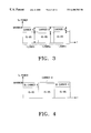
FIG. 8 illustrates the symbol distributer of FIG. 6;
FIG. 9 illustrates block diagrams of a transmission scheme for a forward link using the channel encoder and the symbol distributer according to the present invention;
FIG. 10 is a chart providing a performance comparison among R=1/3 convolutional codes;
FIG. 11 is a chart illustrating a worst performance comparison among R=1/2 convolutional codes using generator polynomials of a convolutional encoder having a coding rate of R=1/3;
FIG. 12 is a chart illustrating a performance comparison among R=1/2 constraint codes for an R=1/6 convolutional code; and
FIG. 13 is a chart illustrating a worst performance comparison among R=1/2 constraint codes using an R=1/6 convolutional encoder having a good performance.
DETAILED DESCRIPTION OF THE PREFERRED EMBODIMENTS
A preferred embodiment of the present invention will be described herein below with reference to the accompanying drawings. In the following description, well known functions or constructions are not described in detail since they would obscure the invention in unnecessary detail.
The word “symbol” as used herein refers to a coded data bit outputted from an encoder. For convenience of explanation, it is assumed that the multicarrier communication system is a three-carrier CDMA communication system. It is contemplated that the present invention can be embodied in other types of communication systems, such as Time Division Multiple Access (TDMA).
**NOTE: The following descriptions are under review. The completed specification and claims will be forwarded by tomorrow.
The present invention provides a device and method for improving system performance in a communication system supporting both the IS-95 system and the multicarrier system, wherein transmission signals of the two different systems are overlaid at the same frequence bands. In the present device and method, the coded symbols are distributed such that performance degradation is minimized during decoding of the damaged symbols, and then the distributed coded bits are assigned to the respective carriers. Thus, even if one of the carriers has interference during reception, it is possible to perform decoding for only the coded bits transmitted via the other carriers, thereby improving system performance.
Moreover, in the forward link, an R=1/6 convolutional code can be used for a channel encoder. Therefore, when the channel encoder generates R=1/6 convolutional codes, it is very difficult to find R=1/6 convolutional codes having a good decoding performance. Accordingly, the present invention is directed to generating R=1/6 convolutional codes with a good decoding performance and distributing the generated convolutional codes to multiple carriers. The R=1/6 convolutional codes generated according to the present invention exhibit good performance in both a multicarrier CDMA communication system and a DS-CDMA communication system.
A description will now be given as to a method of generating symbols for maximizing channel performance and distributing the generated symbols in a CDMA communication system according to an embodiment of the present invention. For convenience, the present invention is described herein below with reference to a multicarrier CDMA communication system.
First, reference will be made to R=1/6 convolutional codes for a multicarrier CDMA communication system using three carriers. FIG. 6 illustrates a convolutional encoder 601 and a symbol distributer 602 according to an embodiment of the present invention. The convolutional encoder 601 encodes one input data bit into six symbols which are allocated to three carriers A, B and C. For symbol allocation, the symbol distributer 602 uniformly distributes the six input bits to the three carriers by two bits. The symbol distributer 602 distributes the symbols outputted from the convolutional encoder 601, taking into consideration how many carriers are damaged out of the three carriers. By using this symbol distribution method, even though one or two of the three carriers are damaged, performance degradation in channel decoding is minimized.
A description will now be made as to a method for designing the symbol distributer 602. A bit error rate (BER) value after channel decoding depends primarily on the number of damaged portions of the symbols which were coded by a channel encoder. Even though the coded symbols are damaged, the symbols located at portions which are least likely to degrade system performance are uniformly distributed to the carriers. Accordingly, even though the symbols for a certain channel are all damaged, an increase in the BER value can be minimized after channel decoding by distributing the non-damaged symbols (or the damaged symbols which are the least likely to degrade system performance) to the carriers.
In addition, during transmission, the symbols outputted from a constituent encoder in the channel encoder are distributed to the carriers; during decoding, a constituent decoder in a channel decoder is selected such that the BER can be low, even though the symbols for a certain carrier are all damaged.
Selection of the constituent decoder in the channel decoder will now be described. First, reference will be made to a convolutional cod having a constraint length of K=9 and a rate of R=1/3. In the following description, generator polynomials gi are represented by an octal number. The convolutional code with K=9 and R=1/3 has a free distance of dfree=18. It is noted that there exist 5685 sets when a search is made for convolutional codes having K=9, R=1/3 and dfree=18, by changing generator polynomials g1, g2, and g3. Only non-catastrophic codes are selected. In addition, it is necessary to prevent performance degradation, even though a certain carrier is damaged, when selecting convolutional codes to be provided to the multicarrier system. Accordingly, it is preferable to maximize the free distance value.
In selecting a reference code for performance comparison, a convolutional code of (g1, g2, g3)=(557, 663, 711) is selected and used; this is the same code used in the IS-95 system. In the IS-95 system, a free distance of the convolutional code is dfree=18, and free distances between constituent codes are dfree(g557,g663)=9, dfree(g557,g711)=11, and dfree(g663,g711)=10. Further, a performance of a convolutional code can be predicted using a BER upper limit formula, which is determined by a transfer function. For the IS-95 system, a transfer function of a convolutional code is T(D,I)|I=1=5D18+7D20+O(D21), and a BER upper limit formula is (∂/∂I)T(D,I)|I=111D18+32D20+O(D21).
When the convolutional code for the IS-95 system is viewed in light of a constituent code, a catastrophic error propagation occurs at a combination of generator polynomials g1 and g2. Therefore, when the convolutional codes for the IS-95 system are used for the multicarrier system, it is necessary to appropriately use interleaving and puncturing. Since the IS-95 convolutional codes cause catastrophic error propagation, it is necessary to search for new convolutional codes suitable for the multicarrier system. For K=9, dfree(gi,gj)≦12, it is found from a complete computer search that there is no convolutional code for which a free distance between constituent codes is always 12. Therefore, there are only eight convolutional codes having the free distance of dfree(gi,gj)≧11. Here, not only the convolutional codes, but also the constituent codes are non-catastrophic. Since a first term of the BER upper limit formula is most influential, first and eighth convolutional codes are considered to be the most optimal codes. Further, since the pairs of first and eighth convolutional codes; second and seventh codes; third and fourth codes; and fifth and sixth codes are in reciprocal relation, they are essentially the same codes. Therefore, only four convolutional codes exist.
Table 1 provides characteristics of a convolutional encoder with K=9 and R=1/3.
TABLE 1
No Generator Polynomial Remarks
1 467 Free Distance between Constituent Codes d12=11, d13=11, d23=12
543 Transfer Function, T(D,I)|I=1 4D18+12D20+O(D21)
765 BER Upper Limit Formula 9D18+54D20+O(D21)
2 547 Free Distance between Constituent Codes d12=11, d13=11,(d23=12
643 Transfer Function, T(D,I)|I=1 6D18+9D20+O(D21)
765 BER Upper Limit Formula 19D18+33D20+O(D21)
3 453 Free Distance between Constituent Codes d12=11, d13=12, d23=11
665 Transfer Function, T(D,I)|I=1 5D18+7D20+O(D21)
771 BER Upper Limit Formula 13D18+31D20+O(D21)
4 477 Free Distance between Constituent Codes d12=11, d13=12, d23=11
533 Transfer Function, T(D,I)|I=1 5D18+7D20+O(D21)
651 BER Upper Limit Formula 13D18+31D20+O(D21)
5 561 Free Distance between Constituent Codes d12=11, d13=12, d2311
647 Transfer Function, T(D,I)|I=1 5D18+7D20+O(D21)
753 BER Upper Limit Formula 13D18+31D20+O(D21)
6 435 Free Distance between Constituent Codes d12=12, d13=11, d23=11
657 Transfer Function, T(D,I)|I=1 5D18+7D20+O(D21)
713 BER Upper Limit Formula 13D18+31D20+O(D21)
7 537 Free Distance between Constituent Codes d12=12, d13=11, d23=11
613 Transfer Function, T(D,I)|I=1 6D18+9D20+O(D21)
715 BER Upper Limit Formula 19D18+33D20+O(D21)
8 537 Free Distance between Constituent Codes d12=12, d13=11, d23=11
615 Transfer Function, T(D,I)|I=1 4D18+12D20+O(D21)
731 BER Upper Limit Formula 9D18+54D20+O(D21)
In Table 1, d12 in a first term means d(467,543) and hereinafter is used to provide the same meaning. For information, when the codes are compared with the IS-95 codes in light of the first term of the BER upper limit formula, the first and eighth codes are superior in performance to the IS-95 codes, the third, fourth, fifth and sixth codes are similar in performance to the IS-95 codes and the second and seventh codes are inferior in performance to the IS-95 codes. Therefore, it is preferable to use the eighth (or first) code.
In the meantime, there exist four or more codes whose free distances among the constituent codes are 12, 12 and 10; among these codes, a generator polynomial for a superior code in the light of the first term of the BER upper limit formula is (g1,g2,g3)=(515, 567, 677). Shown in FIG. 10 is the simulation result for performances of the convolutional code with R=1/3 in a AWGN (Additive White Gaussian Noise) environment in the case where the multicarrier (three-carrier) system has an optimal performance without damage of the respective carriers. In the following descriptions, the simulations of FIGS. 11-13 are all performed in the AWGN environment. <Case 1> represents a R=1/3 convolutional code for an IS-95 system, and <Case 2> and <Case 3> represent a R=1/3 convolutional code searched for using the inventive method.
<Case 1> IS-95 (g1=557, g2=663, g3=711)→dfree=18
<Case 2> g1=731, g2=615, g3=537→dfree=18 dfree(g1,g2)=11, dfree(g1,g3)=11, dfree(g2,g3)=12
<Case 3> g1=515, g2=567, g3=677→dfree=18 dfree(g1,g2)=11, dfree(g1,g3)=12, dfree(g2,g3)=10
A description will now be made regarding the case where the R=1/3 convolutional code is applied to the three-carrier system and a certain one of the three carriers is damaged (or lost). Although the original coding rate is ⅓, the loss of one carrier causes the coding rate to be equal to ½. Therefore, shown in FIG. 11 is the simulation results for the 1/2 convolutional codes using the generator polynomials for the 1/3 convolutional codes. In FIG. 11, the respective conditions can be explained by <Case 1> through <Case 4>. FIG. 11 illustrates the worst performance graph for the R=1/2 convolutional codes using the generator polynomials for the R=1/3 convolutional code.
<Case 1> Optimal 1/2 convolutional code→g1=561, g2=753, dfree(g1,g2)=12
<Case 2> the worst performance, g1=557, g2=711 out of three R=1/2 convolutional codes using the generator polynomial (557, 663, 711) for a 1/3 convolutional code used for the IS-95 system→catastrophic error propagation occurs
<Case 3> the worst performance, g1=731, g2=615 (dfre(g1,g2)=11) for R=1/2 convolutional code using the generator polynomial (731, 615, 537) for a R=1/3 convolutional code
<Case 4> the worst performance, g1=567, g2=677 (dfre(g1,g2)=10) for R=1/2 convolutional code using the generator polynomial (515, 567, 677) for a R=1/3 convolutional code
When one carrier is damaged in a three-carrier system using an R=1/3 convolutional code, the coding rate becomes equal to R=1/2. In this case, a symbol distribution method for the symbol distributer is found by appropriately distributing the original R=1/3 convolutional codes to the three carriers using the symbol deleting matrixes shown below to minimize performance degradation even though the coding rate becomes R=1/2. In the simplest method, the two symbol deleting matrixes shown below are generated. In the symbol deleting matrixes, “0” means the case where a carrier to which the corresponding symbol is provided is damaged, and “1” means the case where the carrier to which the corresponding symbol is provided is not damaged. This means that the symbols corresponding to “0” are all allocated to a certain carrier which is damaged during transmission. Therefore, one of the following various patterns of the symbol deleting matrix is selected which minimizes performance degradation even though one carrier is damaged, and the symbol distributer 602 provides the symbols to the respective carriers using the selected pattern. The following symbol deleting matrixes are used for finding a pattern to be used by the symbol distributer 602 to correctly allocate the symbols to the respective carriers. D 1 = [ 0 1 1 1 0 1 1 1 0 ] D 2 = [ 1 1 0 1 0 1 0 1 1 ]
Figure US06400703-20020604-M00001
Further, an m-sequence having an 8-bit length is generated over a two-stage GF(3) using an m-sequence. For a ninth convolutional code, a sequence {1,2,0,2,2,1,0,1,2} is generated and then, the following symbol deleting matrix D3 is generated using the sequence. D 3 = [ 1 1 0 1 1 1 0 1 1 0 1 1 1 1 0 1 0 1 1 0 1 0 0 1 1 1 0 ]
Figure US06400703-20020604-M00002
Further, the following symbol deleting matrixes D4 and D5 are generated by changing the rows of the symbol deleting matrix D3. D 4 = [ 1 0 1 0 0 1 1 1 0 1 1 0 1 1 1 0 1 1 0 1 1 1 1 0 1 0 1 ] D 5 = [ 0 1 1 1 1 0 1 0 1 1 0 1 0 0 1 1 1 0 1 1 0 1 1 1 0 1 1 ]
Figure US06400703-20020604-M00003
In addition, a sequence {2,1,0,1,1,0,1,2,1,0,0,0,2,1,2} is obtained by generating 15 random numbers over GF(3) using a random number, and the following symbol deleting matrix D6 using the above sequence. D 6 = [ 1 1 0 1 1 0 1 1 1 0 0 0 1 1 1 1 0 1 0 0 1 0 1 0 1 1 1 1 0 1 0 1 1 1 1 1 1 0 1 1 1 1 0 1 0 ]
Figure US06400703-20020604-M00004
Also, the following symbol deleting matrixes D7 and D8 are generated by changing the rows as in the method using the m-sequence. D 7 = [ 0 1 1 1 1 1 1 0 1 1 1 1 0 1 0 1 1 0 1 1 0 1 1 1 0 0 0 1 1 1 1 0 1 0 0 1 0 1 0 1 1 1 1 0 1 ] D 8 = [ 1 0 1 0 0 1 0 1 0 1 1 1 1 0 1 0 1 1 1 1 1 1 0 1 1 1 1 0 1 0 1 1 0 1 1 0 1 1 1 0 0 0 1 1 1 ]
Figure US06400703-20020604-M00005
Next, a description will be made regarding a convolutional code having a symbol rate of 1/6. A K=9, R=1/6 convolutional code has a free distance of dfree=37. In searching for the convolutional codes having a free distance of dfree=37 by randomly changing the generator polynomials g1, g2, . . . g6, the following conditions should be satisfied.
First, it should be a R=1/6 convolutional code with a good decoding performance.
Second, it should be a R=1/4 convolutional code with a good decoding performance which has polynomials (g1,g2,g3,g4), (g1,g2,g5,g6) and (g3,g4,g5,g6), considering the case that one of three carriers is damaged in the three-carrier system.
Third, it should be a 1/2 convolutional code with a good decoding performance which has generator polynomials (g1,g2), (g3,g4) and (g5,g6), considering the case that two of three carriers are damaged in the three-carrier system.
With respect to the second and third conditions, performance degradation is minimized even though one or two of the three carriers are completely off, providing for the multicarrier system in which six output bits of the convolutional code are allocated to three carriers by two bits. From this point of view, it is preferable that the R=1/4 convolutional code and the R=1/2 convolutional code have the maximum free distance.
A method of searching for a R=1/2 convolutional code satisfying the third condition becomes apparent from the following description. There exist 35 non-catastrophic convolutional codes with R=1/2, K=9 and dfree=12. An upper limit formula for the BER is given as follows (a coefficient c12 of the most important term D12 in determining the BER ranges from 33 to 123):
(∂/∂I)T(D,I)|I=1 =c 12 D 12 +c 13 D 13+. . .
First, for the R=1/6 convolutional codes, there exist 180 R=1/6 convolutional codes with dfree=37, satisfying the third condition. It is assumed that dfree(g2i−1,g2i)=12. Here, there exist 58 convolutional codes in which the first term of the BER upper limit formula for the R=1/6 convolutional code has a coefficient of c37=1. The following are the R=1/6 convolutional codes selected among the 58 convolutional codes after conducting a performance verification or analysis.
1) (457, 755, 551, 637, 523, 727): c38=4 (NO=1)
2) (457, 755, 551, 637, 625, 727): c38=4 (NO=3)
3) (457, 755, 455, 763, 625, 727): c38=4 (NO=5)
4) (515, 677, 453, 755, 551, 717): c38=6 (NO=7)
5) (515, 677, 453, 755, 551, 717): c38=6 (NO=9)
6) (515, 677, 557, 651, 455, 747): c38=6 (NO=11)
7) (457, 755, 465, 753, 551, 637): c38=6 (NO=13)
8) (515, 677, 551, 717, 531, 657): c38=8 (NO=27)
9) (515, 677, 455, 747, 531, 657): c38=8 (NO=29)
10) (453, 755, 557, 751, 455, 747): c38=10 (NO=31)
11) (545, 773, 557, 651, 551, 717): c38=12 (NO=51)
12) (453, 755, 457, 755, 455, 747): c38=20 (NO=57)
The following are 5 R=1/6 convolutional codes with a good decoding performance selected among the 12 performance-verified 1/6 convolutional codes listed above.
1) (457, 755, 551, 637, 523, 727): c38=4 (NO=1)
2) (515, 677, 453, 755, 551, 717): c38=6 (NO=7)
3) (545, 773, 557, 651, 455, 747): c38=6 (NO=8)
4) (515, 677, 557, 651, 455, 747): c38=6 (NO=11)
5) (515, 677, 455, 747, 531, 657): c38=8 (NO=29)
A performance of the R=1/2 convolutional codes using five generator polynomials for the R=1/6 convolutional code are verified, and further, a performance of the R=1/4 convolutional codes using five generator polynomials for the R=1/6 convolutional code are also verified. First, a transfer function for the R=1/2 convolutional codes will be described with reference to Table 2 in which the generator polynomials are represented by octal numbers.
TABLE 2
BER Upper Limit Formula,
No 1/2 Generator Polynomial Coeff c12, c13, c14
 1 435, 657 (33, 0, 281)
 2 561, 753 (33, 0, 281)
 3 515, 677 (38, 106, 238)
 4 545, 773 (38, 106, 238)
 5 463, 755 (38, 0, 274)
 6 557, 631 (38, 0, 274)
 7 557, 751 (40, 33, 196)
 8 457, 755 (40, 33, 196)
 9 453, 755 (40, 0, 271)
10 557, 651 (40, 0, 271)
11 471, 673 (50, 0, 298)
12 537, 615 (50, 0, 360)
13 543, 765 (50, 0, 360)
14 455, 747 (50, 0, 395)
15 551, 717 (50, 0, 395)
16 465, 753 (52, 0, 287)
17 531, 657 (52, 0, 287)
18 455, 763 (52, 0, 339)
19 551, 637 (52, 0, 339)
20 561, 735 (57, 0, 355)
21 435, 567 (57, 0, 355)
22 561, 755 (57, 0, 390)
23 435, 557 (57, 0, 390)
24 465, 771 (58, 0, 321)
25 477, 531 (58, 0, 321)
26 537, 613 (67, 0, 472)
27 643, 765 (67, 0, 472)
28 523, 727 (68, 0, 349)
29 625, 727 (68, 0, 349)
30 523, 755 (68, 0, 363)
31 557, 625 (68, 0, 363)
32 453, 771 (70, 0, 496)
33 477, 651 (70, 0, 496)
34 515, 567 (123, 0, 589)
35 545, 735 (123, 0, 589)
A R=1/2 convolutional code with the highest performance is searched by verifying the performance of the respective R=1/2 convolutional codes in Table 2. In addition, the performance of each of the R=1/2 convolutional codes is compared with the performance of the optimal R=1/2 convolutional code used by the IS-95 system.
<Case 1> generator polynomial→(435, 657)8, NO=1, c12=33
<case 2> generator polynomial→(561, 753)8, NO=2, c12=33, an optimal R=1/2 convolutional code used for the IS-95 standard
<Case 3> generator polynomial→(557, 751)8, NO=7, c12=40
<Case 4> generator polynomial→(453, 755)8, NO=9, c12=40
<Case 5> generator polynomial→(471, 673)8, NO=11, c12=50
<Case 6> generator polynomial→(531, 657)8, NO=17, c12=52
<Case 7> generator polynomial→(561, 755)8, NO=22, c12=57
<Case 8> generator polynomial→(465, 771)8, NO=24, c12=58
A performance comparison among the respective cases is shown in FIG. 12. FIG. 12 illustrates a performance comparison among R=1/2 constituent codes for the R=1/6 convolutional code. It is noted that the R=1/2 constituent codes for the R=1/6 convolutional code are similar in performance to the optimal R=1/2 convolutional code.
Table 3 illustrates transfer functions for the R=1/6 convolutional codes.
TABLE 3
1/6 Generator Polynomial 1/6 BER coeff. 1/2 BER coeff. c 12 1/4 BER coeff. c24
No (Octal Number) c37, c38, c39 (1,2; 3,4; 5,6) (1234; 1256; 3456)
 1 457 755 551 637 523 727 (1, 4, 9) (40, 52, 68) (8, 2, 5)
 2 557 751 455 763 625 727 (1, 4, 9) (40, 52, 68) (8, 2, 5)
 3 457 755 551 637 625 727 (1, 4, 9) (40, 52, 68) (8, 6, 5)
 4 557 751 455 763 523 727 (1, 4, 9) (40, 52, 68) (8, 6, 5)
 5 457 755 455 763 625 727 (1, 4, 9) (40, 52, 68) (14, 6, 5)
 6 557 751 551 637 523 727 (1, 4, 9) (40, 52, 68) (14, 6, 5)
 7 515 677 453 755 551 717 (1, 6, 9) (38, 40, 50) (4, 2, 1)
 8 545 773 557 651 455 747 (1, 6, 9) (38, 40, 50) (4, 2, 1)
 9 515 677 557 651 551 717 (1, 6, 12) (38, 40, 50) (4, 2, 1)
10 545 773 453 755 455 747 (1, 6, 12) (38, 40, 50) (4, 2, 1)
11 515 677 557 651 455 747 (1, 6, 12) (38, 40, 50) (4, 8, 1)
12 545 773 453 755 551 717 (1, 6, 12) (38, 40, 50) (4, 8, 1)
13 457 755 465 753 551 637 (1, 6, 12) (40, 52, 52) (6, 8, 5)
14 457 755 531 657 551 637 (1, 6, 12) (40, 52, 52) (6, 8, 5)
15 557 751 455 763 465 753 (1, 6, 12) (40, 52, 52) (8, 6, 5)
16 557 751 455 763 531 657 (1, 6, 12) (40, 52, 52) (8, 6, 5)
17 557 751 465 753 551 637 (1, 6, 12) (40, 52, 52) (6, 14, 5)
18 557 751 531 657 551 637 (1, 6, 12) (40, 52, 52) (6, 14, 5)
19 457 755 455 763 465 753 (1, 6, 12) (40, 52, 52) (14, 6, 5)
20 457 755 455 763 531 657 (1, 6, 12) (40, 52, 52) (14, 6, 5)
21 557 751 455 763 515 567 (1, 6, 9) (40, 52, 123) (8, 6, 1)
22 457 755 551 637 545 735 (1, 6, 9) (40, 52, 123) (8, 6, 1)
23 457 755 551 637 515 567 (1, 6, 9) (40, 52, 123) (8, 8, 1)
24 557 751 455 763 545 735 (1, 6, 9) (40, 52, 123) (8, 8, 1)
25 557 751 551 637 545 567 (1, 6, 9) (40, 52, 123) (14, 6, 1)
26 457 755 455 763 545 735 (1, 6, 9) (40, 52, 123) (14, 6, 1)
27 515 677 551 717 531 657 (1, 8, 6) (38, 50, 52) (2, 6, 4)
28 545 773 455 747 465 753 (1, 8, 6) (38, 50, 52) (2, 6, 4)
29 515 677 455 747 531 657 (1, 8, 6) (38, 50, 52) (8, 6, 4)
30 545 773 551 717 465 753 (1, 8, 6) (38, 50, 52) (8, 6, 4)
31 453 755 557 751 455 747 (1, 10, 15) (40, 40, 50) (4, 1, 6)
32 457 755 557 651 551 717 (1, 10, 15) (40, 40, 50) (4, 6, 1)
33 453 755 557 751 551 717 (1, 10, 15) (40, 40, 50) (4, 1, 12)
34 457 755 557 651 455 747 (1, 10, 15) (40, 40, 50) (4, 11, 1)
35 453 755 457 755 551 717 (1, 10, 15) (40, 40, 50) (14, 1, 6)
36 557 651 557 751 455 747 (1, 10, 15) (40, 40, 50) (14, 1, 6)
37 457 755 551 637 557 625 (1, 10, 9) (40, 52, 68) (8, 2, 11)
38 557 751 455 763 523 755 (1, 10, 9) (40, 52, 68) (8, 2, 11)
39 457 755 455 763 523 727 (1, 10, 9) (40, 52, 68) (14, 2, 5)
40 457 755 455 763 557 625 (1, 10, 9) (40, 52, 68) (14, 2, 5)
41 557 751 551 637 523 755 (1, 10, 9) (40, 52, 68) (14, 2, 5)
42 557 751 551 637 625 727 (1, 10, 9) (40, 52, 68) (14, 2, 5)
43 457 755 551 637 523 755 (1, 10, 9) (40, 52, 68) (8, 14, 5)
44 557 751 455 763 557 625 (1, 10, 9) (40, 52, 68) (8, 14, 5)
45 545 773 455 763 515 567 (1, 10, 6) (38, 52, 123) (8, 6, 1)
46 545 773 551 637 515 567 (1, 10, 6) (38, 52, 123) (8, 6, 1)
47 515 677 455 763 545 735 (1, 10, 6) (38, 52, 123) (8, 6, 1)
48 515 677 551 637 545 735 (1, 10, 6) (38, 52, 123) (8, 6, 1)
49 515 677 551 637 515 567 (1, 10, 6) (38, 52, 123) (8, 18, 1)
50 545 773 455 763 545 735 (1, 10, 6) (38, 52, 123) (8, 18, 1)
51 545 773 557 651 551 717 (1, 12, 9) (38, 40, 50) (4, 8, 1)
52 515 677 453 755 455 747 (1, 12, 9) (38, 40, 50) (4, 8, 1)
53 457 755 455 763 515 567 (1, 12, 9) (40, 52, 123) (14, 8, 1)
54 557 751 551 637 545 735 (1, 12, 9) (40, 52, 123) (14, 8, 1)
55 515 677 455 763 515 567 (1, 16, 6) (38, 52, 123) (8, 18, 1)
56 545 773 551 637 545 735 (1, 16, 6) (38, 52, 123) (8, 18, 1)
57 453 755 457 755 455 747 (1, 20, 15) (40, 40, 50) (14, 1, 2)
58 557 651 557 751 551 717 (1, 20, 15) (40, 40, 50) (14, 1, 2)
The worst performance of the R=1/2 constituent codes using 5 R=1/6 convolutional are as follows, with reference to Table 3.
<Case 1> the worst performance of a R=1/6 convolutional code (NO=1) having generator polynomials of (457, 755, 551, 637, 523, 727)8→(523, 727)8, c12=68
<Case 2> the worst performance of a R=1/6 convolutional code (NO=7) having generator polynomials of (515, 677, 453, 755, 551, 717)8→(515, 677)8, c12=38
<Case 3> the worst performance of a R=1/6 convolutional code (NO=8) having generator polynomials of (545, 773, 557, 651, 455, 747)8→(545, 773)8, c12=38
<Case 4> the worst performance of a R=1/6 convolutional code (NO=11) having generator polynomials of (551, 677, 557, 651, 455, 747)8→(551, 677)8, c12=38
<Case 5> the worst performance of a R=1/6 convolutional code (NO=29) having generator polynomials of (515, 677, 455, 747, 531, 657)8→(515, 677)8, c12=38
The worst performances for the R=1/4 constituent codes are as follows using the R=1/6 convolutional codes whose performances are verified for the R=1/2 constituent codes.
<Case 1> the worst performance of a R=1/6 convolutional code (NO=1) having generator polynomials of (457, 755, 551, 637, 523, 727)8→(551, 637, 523, 727)8, c24=5
<Case 2> the worst performance of a R=1/6 convolutional code (NO=7) having generator polynomials of (515, 677, 453, 755, 551, 717)8→(515, 677, 551, 717)8, c24=2
<Case 3> the worst performance of a R=1/6 convolutional code (NO=8) having generator polynomials of (545, 773, 557, 651, 455, 747)8→(545, 773, 455, 747)8, c24=2
<Case 4> the worst performance of a R=1/6 convolutional code (NO=11) having generator polynomials of (551, 677, 557, 651, 455, 747)8→(551, 677, 557, 651)8, c24=4
<Case 5> the worst performance of a R=1/6 convolutional code (NO=29) having generator polynomials of (515, 677, 455, 747, 531, 657)8→(515, 677, 531, 657)8, c24=6
FIG. 13 illustrates a comparison among the worst performances of R=1/2 constituent codes using R=1/6 convolutional code with the highest performance.
The following are two R=1/6 convolutional codes with a good decoding performance which were selected among the R=1/6 convolutional codes whose performances are verified for various cases in the above examples.
1) (515, 677, 453, 755, 551, 717)8: c38=6 (NO=7)
2) (545, 773, 557, 651, 455, 747)8: c38=6 (NO=8)
Further, to search for a symbol deleting pattern used for the three-carrier system, various symbol deleting matrixes are considered for the situation where one carrier is damaged. i.e., where the R=1/6 convolutional codes change to R=1/4 convolutional codes. The reason for searching for the symbol deleting matrix pattern is the same as described for the R=1/3 convolutional codes. The following matrixes can be used as a symbol deleting matrix pattern for a method of distributing symbols for R=1/6 convolutional codes. D 1 = [ 0 1 1 0 1 1 1 0 1 1 0 1 1 1 0 1 1 0 ] D 2 = [ 1 1 0 1 1 0 1 0 1 1 0 1 0 1 1 0 1 1 ] D 3 = [ 0 1 1 1 0 1 1 1 0 0 1 1 1 0 1 1 1 0 ] D 4 = [ 1 1 0 1 0 1 0 1 1 1 1 0 1 0 1 0 1 1 ] D 5 = [ 0 1 1 1 0 1 1 0 1 1 1 0 0 1 0 1 1 1 1 0 1 0 1 1 1 1 0 1 0 1 1 1 1 0 1 0 ] D 6 = [ 1 1 1 0 1 0 1 1 0 1 0 1 1 0 1 0 1 1 0 1 0 1 1 1 1 0 1 1 1 0 0 1 1 1 0 1 ] D 7 = [ 0 1 1 1 0 1 1 1 0 1 1 0 1 0 1 0 1 1 ] D 8 = [ 1 1 0 1 0 1 0 1 1 0 1 1 1 0 1 1 1 0 ] D 9 = [ 0 1 1 1 1 0 1 0 1 1 0 1 1 1 0 0 1 1 0 1 1 1 1 0 1 0 1 1 0 1 1 1 0 0 1 1 ] D 10 = [ 1 1 0 0 1 1 1 0 1 1 0 1 0 1 1 1 1 0 1 1 0 0 1 1 1 0 1 1 0 1 0 1 1 1 1 0 ] D 11 = [ 0 1 1 1 1 0 1 0 1 1 0 1 1 1 0 0 1 1 1 1 0 0 1 1 1 0 1 1 0 1 0 1 1 1 1 0 ] D 12 = [ 1 1 0 0 1 1 1 0 1 1 0 1 0 1 1 1 1 0 0 1 1 1 1 0 1 0 1 1 0 1 1 1 0 0 1 1 ]
Figure US06400703-20020604-M00006
Taking into consideration the case where two carriers are damaged in the three-carrier system, the following symbol deleting matrix patterns can be used in a method of distributing symbols for R=1/2 symbol-deleted convolutional codes using generator polynomials for the R=1/6 convolutional codes with a good decoding performance. D 2 - 1 = [ 1 0 0 1 0 0 0 1 0 0 1 0 0 0 1 0 0 1 ] D 2 - 2 = [ 0 0 1 0 0 1 0 1 0 0 1 0 1 0 0 1 0 0 ] D 2 - 3 = [ 1 0 0 0 1 0 0 0 1 1 0 0 0 1 0 0 0 1 ] D 2 - 4 = [ 0 0 1 0 1 0 1 0 0 0 0 1 0 1 0 1 0 0 ] D 2 - 5 = [ 1 0 0 0 1 0 0 1 0 0 0 1 1 0 1 0 0 0 0 1 0 1 0 0 0 0 1 0 1 0 0 0 0 1 0 1 ] D 2 - 6 = [ 0 0 0 1 0 1 0 0 1 0 1 0 0 1 0 1 0 0 1 0 1 0 0 0 0 1 0 0 0 1 1 0 0 0 1 0 ] D 2 - 7 = [ 1 0 0 0 1 0 0 0 1 0 0 1 0 1 0 1 0 0 ] D 2 - 8 = [ 0 0 1 0 1 0 1 0 0 1 0 0 0 1 0 0 0 1 ] D 2 - 9 = [ 1 0 0 0 0 1 0 1 0 0 1 0 0 0 1 1 0 0 1 0 0 0 0 1 0 1 0 0 1 0 0 0 1 1 0 0 ] D 2 - 10 = [ 0 0 1 1 0 0 0 1 0 0 1 0 1 0 0 0 0 1 0 0 1 1 0 0 0 1 0 0 1 0 1 0 0 0 0 1 ] D 2 - 11 = [ 1 0 0 0 0 1 0 1 0 0 1 0 0 0 1 1 0 0 0 0 1 1 0 0 0 1 0 0 1 0 1 0 0 0 0 1 ] D 2 - 12 = [ 0 0 1 1 0 0 0 1 0 0 1 0 1 0 0 0 0 1 1 0 0 0 0 1 0 1 0 0 1 0 0 0 1 1 0 0 ]
Figure US06400703-20020604-M00007
Turning to FIG. 6, there is shown the convolutional encoder 601 and the symbol distributer 602 according to an embodiment of the present invention. In the exemplary convolutional encoder 601 has a coding rate of R=1/6 and uses generator polynomial or (545, 773, 557, 651, 455, 747). The detailed structure of the R=1/6 convolutional encoder 601 is illustrated in FIG. 7.
Referring to FIG. 7, upon receipt of input data, delays 711-A to 711-H delay the input data bits sequentially. During the sequential delay of the input data bits, exclusive OR gates 721-A to 721-F output coded symbols. The coded symbols of FIG. 7 are provided to the symbol distributer 602 having the structure as shown by FIG. 8.
Referring to FIG. 8, the symbol distributer 602 is implemented by switches 811-A and 811-B. In FIG. 8, when a symbol rate of a clock for controlling the switches 811-A and 811-B is over six times a symbol rate of the symbol distributer 602, the symbols can be distributed without symbol loss. That is, the switch 811-A sequentially receives input symbols g1, g2, g3, g4, g5, g6, g1, g2, g3, . . . , and the switch 811-B distributes the input symbols to output nodes c1, c2, c3, c4, c5 and c6.
FIG. 9 illustrates transmission schemes using the channel encoder 601 and the symbol distributer 602 of FIG. 6. First to fourth CRC generators 911-914 add CRC data in a specified number of bits to input data. Specifically, 12-bit CRC is added to the 172-bit data of the first rate; 8-bit CRC is added to the 80-bit data of the second rate; 6-bit CRC is added to the 40-bit data of the third rate; and 6-bit CRC is added to the 16-bit data of the fourth rate. First to fourth tail bit generators 921-924 add 8 tail bits to the CRC-added data. Therefore, the first tail bit generator 921 outputs 192 bits; the second tail bit generator 922 outputs 96 bits; the third tail bit generator 923 outputs 54 bits; and the fourth tail bit generator 924 outputs 30 bits.
First to fourth encoders 931-934 encode data output from the first to fourth tail bit generators 921-924, respectively. Here, a K=9, R=1/6 convolutional encoder can be used for the encoders 931-934. In this case, the first encoder 931 encodes the 192-bit data output from the first tail bit generator 921 into 1152 symbols of fall rate; the second encoder 932 encodes the 96-bit data output from the second tail bit generator 922 into 576 symbols of ½ rate; the third encoder 933 encodes the 54-bit data output from the third tail bit generator 923 into 324 symbols of about ¼ rate; and the fourth encoder 934 encodes the 30-bit data output from the fourth tail bit generator 924 into 180 symbols of about ⅛ rate.
First to fourth symbol distributers 941-944 distribute the symbols output from the encoders 931-934, respectively. Here, for symbol distribution, a channel controller (not shown) generates control signals for distributing the channel-coded bits such that performance degradation is minimized during decoding of received damaged bits, when the coded symbols being transmitted are overlaid on the symbols of a different system at the same frequency band. The symbol distributers 941-944 then assign the symbols outputted from the encoders 931-934 to the corresponding carriers according to the control signals.
Rate matchers 951-953 each include a symbol repeater and a symbol deletion device. The rate matchers 951-953 match rates of the symbols outputted from the corresponding symbol distributers 942-944 to a rate of the symbols outputted from the symbol distributer 941. First to fourth channel interleavers 961-964 interleave the symbols outputted from the symbol distributer 941 and the rate matchers 951-953, respectively. For the DS-CDMA communication system, the symbol distributers 941-944 of FIG. 9 can be removed.
As described above, in the multicarrier system employing the frequency overlay method, the respective carriers have limited transmission powers according to the loading in the frequency bands of the IS-95 system, which results in loss of data received at one or more carrier frequency bands. To solve this problem, by using the generator polynomials for the channel encoder and a symbol distribution method, it is possible to provide a high coding gain against the data loss due to the carrier loss, thereby preventing degradation of the BER.
While the invention has been shown and described with reference to a certain preferred embodiment thereof, it will be understood by those skilled in the art that various changes in form and details may be made therein without departing from the spirit and scope of the invention as defined by the appended claims.

Claims (15)

What is claimed is:
1. A channel transmission device for use in a code division multiple access (CDMA) communication system using at least two carriers, comprising:
a channel encoder for encoding channel data to be transmitted as symbols at a predetermined coding rate;
a channel controller for generating a symbol distribution signal according to a predetermined symbol deleting matrix pattern, wherein the symbol deleting matrix pattern is constructed to distribute the symbols to the at least two carriers with a minimum performance degradation; and
a symbol distributer for receiving the symbols and distributing said received symbols to the at least two carriers according to the symbol distribution signal.
2. The channel transmission device as claimed in claim 1, wherein the channel encoder is a convolutional encoder with a coding rate of R=1/6.
3. The channel transmission device as claimed in claim 2, wherein the convolutional encoder generates the symbols using one of a plurality of generator polynomials, said generator polynomials being selected from the group included in the following table:
1/6 Generator Polynomial 1/6 BER coeff. 1/2 BER coeff. c12 1/4 BER coeff. c24 No (Octal Number) c37, c38, c39 (1,2; 3,4; 5,6) (1234; 1256; 3456)  1 457 755 551 637 523 727 −149 −405268 −825  2 557 751 455 763 625 727 −149 −405268 −825  3 457 755 551 637 625 727 −149 −405268 −865  4 557 751 455 763 523 727 −149 −405268 −865  5 457 755 455 763 625 727 −149 −405268 −1465   6 557 751 551 637 523 727 −149 −405268 −1465   7 515 677 453 755 551 717 −169 −384050 −421  8 545 773 557 651 455 747 −169 −384050 −421  9 515 677 557 651 551 717 −1612  −384050 −421 10 545 773 453 755 455 747 −1612  −384050 −421 11 515 677 557 651 455 747 −1612  −384050 −481 12 545 773 453 755 551 717 −1612  −384050 −481 13 457 755 465 753 551 637 −1612  −405252 −685 14 457 755 531 657 551 637 −1612  −405252 −685 15 557 751 455 763 465 753 −1612  −405252 −865 16 557 751 455 763 531 657 −1612  −405252 −865 17 557 751 465 753 551 637 −1612  −405252 −6145  18 557 751 531 657 551 637 −1612  −405252 −6145  19 457 755 455 763 465 753 −1612  −405252 −1465  20 457 755 455 763 531 657 −1612  −405252 −1465  21 557 751 455 763 515 567 −169 −4052123  −861 22 457 755 551 637 545 735 −169 −4052123  −861 23 457 755 551 637 515 567 −169 −4052123  −881 24 557 751 455 763 545 735 −169 −4052123  −881 25 557 751 551 637 515 567 −169 −4052123  −1461  26 457 755 455 763 545 735 −169 −4052123  −1461  27 515 677 551 717 531 657 −186 −385052 −264 28 545 773 455 747 465 753 −186 −385052 −264 29 515 677 455 747 531 657 −186 −385052 −864 30 545 773 551 717 465 753 −186 −385052 −864 31 453 755 557 751 455 747 −11015  −404050 −416 32 457 755 557 651 551 717 −11015  −404050 −461 33 453 755 557 751 551 717 −11015  −404050 −4112  34 457 755 557 651 455 747 −11015  −404050 −4111  35 453 755 457 755 551 717 −11015  −404050 −1416  36 557 651 557 751 455 747 −11015  −404050 −1416  37 457 755 551 637 557 625 −1109  −405268 −8211  38 557 751 455 763 523 755 −1109  −405268 −8211  39 457 755 455 763 523 727 −1109  −405268 −1425  40 457 755 455 763 557 625 −1109  −405268 −1425  41 557 751 551 637 523 755 −1109  −405268 −1425  42 557 751 551 637 625 727 −1109  −405268 −1425  43 457 755 551 637 523 755 −1109  −405268 −8145  44 557 751 455 763 557 625 −1109  −405268 −8145  45 545 773 455 763 515 567 −1106  −3852123  −861 46 545 773 551 637 515 567 −1106  −3852123  −861 47 515 677 455 763 545 735 −1106  −3852123  −861 48 515 677 551 637 545 735 −1106  −3852123  −861 49 515 677 551 637 515 567 −1106  −3852123  −8181  50 545 773 455 763 545 735 −1106  −3852123  −8181  51 545 773 557 651 551 717 −1129  −384050 −481 52 515 677 453 755 455 747 −1129  −384050 −481 53 457 755 455 763 515 567 −1129  −4052123  −1481  54 557 751 551 637 545 735 −1129  −4052123  −1481  55 515 677 455 763 515 567 −1166  −3852123  −8181  56 545 773 551 637 545 735 −1166  −3852123  −8181  57 453 755 457 755 455 747 −12015  −404050 −1412  58 557 651 557 751 551 717 −12015  −404050 −1412 
4. The channel transmission device as claimed in claim 1, wherein the symbol distributer comprises:
a first selector for sequentially multiplexing the received symbols; and
a second selector for distributing the multiplexed symbols to the at least two carriers according to the symbol distribution signal.
5. A channel transmission device for use in a multicarrier code division multiple access (CDMA) communication system using at least two carriers, comprising:
a channel encoder for encoding channel data to be transmitted as symbols at a predetermined coding rate;
a symbol distributer for receiving the symbols and distributing received symbols to the at least two carriers according to a predetermined symbol deleting matrix pattern, wherein the symbol deleting matrix pattern is constructed to distribute the symbols to the at least two carriers with minimum degradation;
a channel interleaver for channel interleaving the distributed symbols;
a demultiplexer for distributing the interleaved symbols to the carriers;
a plurality of orthogonal modulators for generating orthogonally modulated signals by multiplying the distributed interleaved symbols by orthogonal codes for the corresponding channels;
a plurality of spreaders for receiving the orthogonally modulated signals and generating spread signals by multiplying the received orthogonally modulated signals by a spreading code; and
a plurality of transmitters for receiving the spread signals and transmitting the received spread signals using the at least two carriers.
6. The channel transmission device as claimed in claim 5, wherein the channel encoder is a convolutional encoder with a coding rate of R=1/6.
7. The channel transmission device as claimed in claim 6, wherein the convolutional encoder generates the symbols using one of a plurality of generator polynomials, said generator polynomials being selected from the group included in the following table:
1/6 Generator Polynomial 1/6 BER coeff. 1/2 BER coeff. c12 1/4 BER coeff. c24 No (Octal Number) c37, c38, c39 (1,2; 3,4; 5,6) (1234; 1256; 3456)  1 457 755 551 637 523 727 −149 −405268 −825  2 557 751 455 763 625 727 −149 −405268 −825  3 457 755 551 637 625 727 −149 −405268 −865  4 557 751 455 763 523 727 −149 −405268 −865  5 457 755 455 763 625 727 −149 −405268 −1465   6 557 751 551 637 523 727 −149 −405268 −1465   7 515 677 453 755 551 717 −169 −384050 −421  8 545 773 557 651 455 747 −169 −384050 −421  9 515 677 557 651 551 717 −1612  −384050 −421 10 545 773 453 755 455 747 −1612  −384050 −421 11 515 677 557 651 455 747 −1612  −384050 −481 12 545 773 453 755 551 717 −1612  −384050 −481 13 457 755 465 753 551 637 −1612  −405252 −685 14 457 755 531 657 551 637 −1612  −405252 −685 15 557 751 455 763 465 753 −1612  −405252 −865 16 557 751 455 763 531 657 −1612  −405252 −865 17 557 751 465 753 551 637 −1612  −405252 −6145  18 557 751 531 657 551 637 −1612  −405252 −6145  19 457 755 455 763 465 753 −1612  −405252 −1465  20 457 755 455 763 531 657 −1612  −405252 −1465  21 557 751 455 763 515 567 −169 −4052123  −861 22 457 755 551 637 545 735 −169 −4052123  −861 23 457 755 551 637 515 567 −169 −4052123  −881 24 557 751 455 763 545 735 −169 −4052123  −881 25 557 751 551 637 515 567 −169 −4052123  −1461  26 457 755 455 763 545 735 −169 −4052123  −1461  27 515 677 551 717 531 657 −186 −385052 −264 28 545 773 455 747 465 753 −186 −385052 −264 29 515 677 455 747 531 657 −186 −385052 −864 30 545 773 551 717 465 753 −186 −385052 −864 31 453 755 557 751 455 747 −11015  −404050 −416 32 457 755 557 651 551 717 −11015  −404050 −461 33 453 755 557 751 551 717 −11015  −404050 −4112  34 457 755 557 651 455 747 −11015  −404050 −4111  35 453 755 457 755 551 717 −11015  −404050 −1416  36 557 651 557 751 455 747 −11015  −404050 −1416  37 457 755 551 637 557 625 −1109  −405268 −8211  38 557 751 455 763 523 755 −1109  −405268 −8211  39 457 755 455 763 523 727 −1109  −405268 −1425  40 457 755 455 763 557 625 −1109  −405268 −1425  41 557 751 551 637 523 755 −1109  −405268 −1425  42 557 751 551 637 625 727 −1109  −405268 −1425  43 457 755 551 637 523 755 −1109  −405268 −8145  44 557 751 455 763 557 625 −1109  −405268 −8145  45 545 773 455 763 515 567 −1106  −3852123  −861 46 545 773 551 637 515 567 −1106  −3852123  −861 47 515 677 455 763 545 735 −1106  −3852123  −861 48 515 677 551 637 545 735 −1106  −3852123  −861 49 515 677 551 637 515 567 −1106  −3852123  −8181  50 545 773 455 763 545 735 −1106  −3852123  −8181  51 545 773 557 651 551 717 −1129   −384050 −481 52 515 677 453 755 455 747 −1129   −384050 −481 53 457 755 455 763 515 567 −1129  −4052123  −1481  54 557 751 551 637 545 735 −1129  −4052123  −1481  55 515 677 455 763 515 567 −1166  −3852123  −8181  56 545 773 551 637 545 735 −1166  −3852123  −8181  57 453 755 457 755 455 747 −12015  −404050 −1412  58 557 651 557 751 551 717 −12015  −404050 −1412 
8. The channel transmission device as claimed in claim 5, wherein the symbol distributer comprises:
a first selector for sequentially multiplexing the received symbols; and
a second selector for distributing the multiplexed symbols to the at least two carriers according to the symbol distribution signal.
9. A channel transmission method for use in a CDMA communication system using at least two carriers, comprising the steps of:
encoding channel data to be transmitted into symbols at a predetermined coding rate; and
distributing the symbols to the at least two carriers according to a predetermined symbol deleting matrix pattern, wherein the symbol deleting matrix pattern is constructed to distribute the symbols to the at least two carriers with minimum performance degradation.
10. The channel transmission method as claimed in claim 9, wherein the channel encoder is a convolutional encoder with a coding rate of R=1/6.
11. The channel transmission method as claimed in claim 9, the step of distributing the symbols further comprises the steps of:
sequentially multiplexing the received symbols; and
distributing the multiplexed symbols to the at least two carriers according to the symbol distribution signal.
12. A channel encoding device for use in a code division multiple access (CDMA) system comprising:
a plurality of delays for delaying an input data bit to generate first to eight delayed data bits;
a first operator for exclusively ORing the input data bit and the third, fifth, sixth, seventh and eighth delayed data bits to generate a first symbol;
a second operator for exclusively ORing the input data bit and the first, second, third, fifth, sixth and eighth delayed data bits to generate a second symbol;
a third operator for exclusively ORing the input data bit and the second, third, fifth and eighth delayed data bits to generate a third symbol;
a fourth operator for exclusively ORing the input data bit and the first, fourth, fifth, sixth, seventh and eighth delayed data bits to generate a fourth symbol;
a fifth operator for exclusively ORing the input data bit and the first, fourth, sixth and eighth delayed data bits to generate a fifth symbol; and
a sixth operator for exclusively ORing the input data bit and the first, second, fourth, sixth, seventh and eighth delayed data bits to generate a sixth symbol.
13. A channel transmission device for use in a code division multiple access (CDMA) communication system, comprising:
a channel encoder including,
a plurality of delays for delaying an input data bit to generate first to eight delayed data bits;
a first operator for exclusively ORing the input data bit and the third, fifth, sixth, seventh and eighth delayed data bits to generate a first symbol;
a second operator for exclusively ORing the input data bit and the first, second, third, fifth, sixth and eighth delayed data bits to generate a second symbol;
a third operator for exclusively ORing the input data bit and the second, third, fifth and eighth delayed data bits to generate a third symbol;
a fourth operator for exclusively ORing the input data bit and the first, fourth, fifth, sixth, seventh and eighth delayed data bits to generate a fourth symbol;
a fifth operator for exclusively ORing the input data bit and the first, fourth, sixth and eighth delayed data bits to generate a fifth symbol;
a sixth operator for exclusively ORing the input data bit and the first, second, fourth, sixth, seventh and eighth delayed data bits to generate a sixth symbol;
a channel interleaver for receiving the symbols and channel interleaving the received symbols;
an orthogonal modulator for generating an orthogonally modulated signal by multiplying the distributed symbols by an orthogonal code for the channel; and
a spreader for generating a spread signal by multiplying the orthogonally modulated signal by a spreading code.
14. The channel transmission device as claimed in claim 13, wherein the symbol distributer distributes the symbols output from the channel encoder according to a symbol deleting matrix pattern, wherein the symbol deleting matrix pattern is so determined as to distribute the symbols to the respective carriers with a minimized performance degradation even though a specific carrier is damaged.
15. A channel encoding method for use in a CDMA communication system, comprising the steps of:
delaying a received input data bit to generate first to eight delayed data bits;
exclusively ORing the received input data bit and the third, fifth, sixth, seventh and eighth delayed data bits to generate a first symbol;
exclusively ORing the received input data bit and the first, second, third, fifth, sixth and eighth delayed data bits to generate a second symbol;
exclusively ORing the received input data bit and the second, third, fifth and eighth delayed data bits to generate a third symbol;
exclusively ORing the received input data bit and the first, fourth, fifth, sixth, seventh and eighth delayed data bits to generate a fourth symbol;
exclusively ORing the received input data bit and the first, fourth, sixth and eighth delayed data bits to generate a fifth symbol; and
exclusively ORing the received input data bit and the first, second, fourth, sixth, seventh and eighth delayed data bits to generate a sixth symbol.
US09/324,423 1998-05-30 1999-06-01 Device and method for generating and distributing coded symbols in a CDMA communication system Expired - Lifetime US6400703B1 (en)

Applications Claiming Priority (2)

Application Number Priority Date Filing Date Title
KR19980020141 1998-05-30
KR98-20141 1998-05-30

Publications (1)

Publication Number Publication Date
US6400703B1 true US6400703B1 (en) 2002-06-04

Family

ID=19537986

Family Applications (1)

Application Number Title Priority Date Filing Date
US09/324,423 Expired - Lifetime US6400703B1 (en) 1998-05-30 1999-06-01 Device and method for generating and distributing coded symbols in a CDMA communication system

Country Status (14)

Country Link
US (1) US6400703B1 (en)
EP (2) EP1437872B1 (en)
JP (2) JP2002517944A (en)
KR (1) KR100407342B1 (en)
CN (2) CN101222293A (en)
AU (1) AU756159B2 (en)
BR (1) BR9910836A (en)
CA (1) CA2333258C (en)
DE (2) DE69916830T2 (en)
ES (2) ES2240955T3 (en)
ID (1) ID27372A (en)
MY (1) MY128666A (en)
RU (1) RU2197786C2 (en)
WO (1) WO1999063692A1 (en)

Cited By (32)

* Cited by examiner, † Cited by third party
Publication number Priority date Publication date Assignee Title
US20020122398A1 (en) * 1997-09-16 2002-09-05 Yu-Cheun Jou Method and apparatus for transmitting and receiving high speed data in a CDMA communication system using multiple carriers
WO2002084889A2 (en) * 2001-04-16 2002-10-24 Interdigital Technology Corporation Physical layer processing for a wireless communication system using code division multiple access
US20030003938A1 (en) * 2001-06-27 2003-01-02 O'neill Alan Methods and apparatus for supporting group communications
US20030018715A1 (en) * 2001-06-14 2003-01-23 O'neill Alan Enabling foreign network multicasting for a roaming mobile node, in a foreign network, using a persistent address
US20030067905A1 (en) * 1999-08-19 2003-04-10 Mitsubishi Electric Telecom Europe Method for configuring a telecommunication system
US20030135799A1 (en) * 2000-07-17 2003-07-17 Markus Doetsch Method and device for diversity transmission of coded information
US20030223439A1 (en) * 2002-04-08 2003-12-04 O'neill Alan Support of disparate addressing plans and dynamic HA address allocation in mobile IP
US6665833B1 (en) * 1999-07-08 2003-12-16 Nortel Networks Limited Puncturing of convolutional codes
US6675347B1 (en) * 2000-07-19 2004-01-06 Qualcomm, Incorporated Method and apparatus for combined puncturing and repeating of code symbols in a communications system
US20040028007A1 (en) * 2001-07-05 2004-02-12 Atsushi Sumasu Radio communication apparatus and radio communication method
US20040029586A1 (en) * 2002-08-08 2004-02-12 Rajiv Laroia Methods and apparatus for operating mobile nodes in multiple states
WO2004015877A3 (en) * 2002-08-08 2004-04-29 Flarion Technologies Inc Method of creating and utilizing diversity in a multiple carrier communication system
US20040106412A1 (en) * 2002-08-08 2004-06-03 Rajiv Laroia Method of creating and utilizing diversity in multiple carrier communication system
US20040170125A1 (en) * 2001-06-26 2004-09-02 O'neill Alan Methods and apparatus for controlling access link packet flow aggregation and resource allocation in a mobile communications system
US20040229625A1 (en) * 2002-08-08 2004-11-18 Rajiv Laroia Methods and apparatus of enhanced coding in multi-user communication systems
US20050174984A1 (en) * 2004-02-06 2005-08-11 O'neill Alan Methods and apparatus for separating home agent functionality
US6963601B1 (en) * 1999-02-04 2005-11-08 Samsung Electronics Co., Ltd. Apparatus and method for spreading channel data in CDMA communication system using orthogonal transmit diversity
US20060036929A1 (en) * 2000-07-05 2006-02-16 Lg Electronics Inc. Method of configuring transmission in mobile communication system
US7050410B1 (en) * 1999-07-08 2006-05-23 Samsung Electronics Co., Ltd. Apparatus and method for controlling a demultiplexer and a multiplexer used for rate matching in a mobile communication system
US20070298788A1 (en) * 2002-10-15 2007-12-27 Corson Mathew S Profile modification for roaming in a communications environment
US7346646B1 (en) * 1999-10-07 2008-03-18 Siemens Aktiengesellschaft Method and apparatus for transmitting data frames, and a method and apparatus for data rate matching
US20080232449A1 (en) * 2007-03-21 2008-09-25 Farooq Khan Efficient uplink feedback in a wireless communication system
US20080238730A1 (en) * 2007-03-27 2008-10-02 Hughes Network Systems, Llc Method and apparatus for generating low rate turbo codes
US7882346B2 (en) 2002-10-15 2011-02-01 Qualcomm Incorporated Method and apparatus for providing authentication, authorization and accounting to roaming nodes
US20110142150A1 (en) * 2003-08-13 2011-06-16 Qualcomm Incorporated User specific downlink power control channel q-bit
US7970127B2 (en) 2002-05-07 2011-06-28 Interdigital Technology Corporation User equipment identification specific scrambling
US20110222627A1 (en) * 2006-10-26 2011-09-15 Qualcomm Incorporated Method and apparatus for codebook exchange in a multiple access wireless communication system
US8023410B2 (en) 2001-06-26 2011-09-20 Qualcomm Incorporated Messages and control methods for controlling resource allocation and flow admission control in a mobile communications system
US8553595B2 (en) 2003-02-19 2013-10-08 Qualcomm Incorporated Controlled superposition coding in multi-user communication systems
US8593932B2 (en) 2003-05-16 2013-11-26 Qualcomm Incorporated Efficient signal transmission methods and apparatus using a shared transmission resource
US8755313B2 (en) 2007-01-11 2014-06-17 Qualcomm Incorporated Using DTX and DRX in a wireless communication system
US9313784B2 (en) 2005-09-19 2016-04-12 Qualcomm Incorporated State synchronization of access routers

Families Citing this family (12)

* Cited by examiner, † Cited by third party
Publication number Priority date Publication date Assignee Title
KR100396507B1 (en) * 1997-11-17 2003-12-24 삼성전자주식회사 Forward link communicating apparatus of communication system using multicarrier and method for implementing the same
KR100407342B1 (en) * 1998-05-30 2003-11-28 삼성전자주식회사 Apparaus and method for communication in cdma communication system
DE60006071T2 (en) 1999-01-21 2004-05-13 Samsung Electronics Co., Ltd., Suwon METHOD AND DEVICE OF A CDMA SYSTEM
US6229824B1 (en) * 1999-05-26 2001-05-08 Xm Satellite Radio Inc. Method and apparatus for concatenated convolutional endcoding and interleaving
IL141800A0 (en) 1999-07-06 2002-03-10 Samsung Electronics Co Ltd Rate matching device and method for a data communication system
US6804220B2 (en) 2001-05-07 2004-10-12 Qualcomm Incorporated Method and apparatus for generating control information for packet data
US7554944B2 (en) 2004-03-09 2009-06-30 Avage Inc. Signal transmitting method and device for carrying out said method
KR100932486B1 (en) 2004-05-04 2009-12-17 엘지전자 주식회사 Channelization Code Allocation Method in Wireless Mobile Communication System
KR100930893B1 (en) 2004-05-04 2009-12-10 엘지전자 주식회사 Scheduling method for uplink enhanced dedicated channel
CN1917410B (en) * 2005-08-19 2010-12-29 北京信威通信技术股份有限公司 Method for encoding and modulating channel inn SCDMA system
US8605669B2 (en) * 2010-05-06 2013-12-10 Telefonaktiebolaget Lm Ericsson (Publ) System and method for signaling control information in a mobile communication network
CN102684843B (en) * 2012-06-07 2015-01-07 哈尔滨工业大学 Obtaining method of optimal generation polynomial in type-II hybrid automatic repeat request (HARQ) system and repeat system adopting method

Citations (11)

* Cited by examiner, † Cited by third party
Publication number Priority date Publication date Assignee Title
US5521937A (en) * 1993-10-08 1996-05-28 Interdigital Technology Corporation Multicarrier direct sequence spread system and method
US5729526A (en) * 1995-10-31 1998-03-17 Fujitsu Limited Asynchronous transfer mode type multimedia radiocommunication system
US5790549A (en) * 1996-02-29 1998-08-04 Ericsson Inc. Subtractive multicarrier CDMA access methods and systems
US5864543A (en) * 1997-02-24 1999-01-26 At&T Wireless Services, Inc. Transmit/receive compensation in a time division duplex system
WO1999063692A1 (en) * 1998-05-30 1999-12-09 Samsung Electronics Co., Ltd. Device and method for generating and distributing coded symbols in cdma communication system
US6108317A (en) * 1995-11-01 2000-08-22 Stm Wireless, Inc. Cyclic code phase multiple access for inbound satellite communications
WO2000049780A1 (en) * 1999-02-16 2000-08-24 Motorola Inc. Interleaving method and apparatus for orthogonal transmit diversity and multi-carriers cdma communication systems
US6151328A (en) * 1998-12-31 2000-11-21 Lg Information & Communications Ltd. Apparatus and method for controlling power in code division multiple access system
US6178158B1 (en) * 1996-10-14 2001-01-23 Nippon Telegraph & Telephone Corporation Method and apparatus for transmission and reception
US6240287B1 (en) * 1998-10-06 2001-05-29 Lucent Technologies Inc. Processing overload control at base stations of cellular wireless communication systems
US6272183B1 (en) * 1997-08-22 2001-08-07 Siemens Aktiengesellschaft Method for data transmission on transmission channels in a digital transmission system

Family Cites Families (12)

* Cited by examiner, † Cited by third party
Publication number Priority date Publication date Assignee Title
US4312070A (en) * 1979-12-07 1982-01-19 Motorola, Inc. Digital encoder-decoder
JPH0728228B2 (en) * 1986-07-08 1995-03-29 日本電気株式会社 Convolutional encoder
US5159608A (en) * 1991-08-28 1992-10-27 Falconer David D Method and apparatus for using orthogonal coding in a communication system
JP2915245B2 (en) * 1993-05-10 1999-07-05 帝人株式会社 Oxygen concentrator
EP0699334B1 (en) * 1994-02-17 2002-02-20 Motorola, Inc. Method and apparatus for group encoding signals
US5546420A (en) * 1994-04-29 1996-08-13 At&T Corp. Methods of and devices for enhancing communications that use spread spectrum technology by using variable code techniques
GB2302633B (en) * 1995-06-24 2000-02-16 Motorola Ltd Convolutional coder
KR0155319B1 (en) * 1995-11-08 1998-11-16 양승택 5mhz-wide-band cdma channel structure for pcs having 3/5 convolutin code
DE19625054B4 (en) * 1996-06-22 2005-04-14 Deutsche Telekom Ag Method and system for transmitting multi-carrier signals with a reduced peak / average ratio
US6373831B1 (en) * 1997-03-26 2002-04-16 Nortel Networks Ltd. Systems and methods of channel coding and inverse-multiplexing for multi-carrier CDMA systems
US6421333B1 (en) * 1997-06-21 2002-07-16 Nortel Networks Limited Channel coding and interleaving for transmission on a multicarrier system
KR100222408B1 (en) * 1997-08-02 1999-10-01 윤종용 Apparatus and method for transmitting in order to increment information transter volume in digital mobile communication system

Patent Citations (11)

* Cited by examiner, † Cited by third party
Publication number Priority date Publication date Assignee Title
US5521937A (en) * 1993-10-08 1996-05-28 Interdigital Technology Corporation Multicarrier direct sequence spread system and method
US5729526A (en) * 1995-10-31 1998-03-17 Fujitsu Limited Asynchronous transfer mode type multimedia radiocommunication system
US6108317A (en) * 1995-11-01 2000-08-22 Stm Wireless, Inc. Cyclic code phase multiple access for inbound satellite communications
US5790549A (en) * 1996-02-29 1998-08-04 Ericsson Inc. Subtractive multicarrier CDMA access methods and systems
US6178158B1 (en) * 1996-10-14 2001-01-23 Nippon Telegraph & Telephone Corporation Method and apparatus for transmission and reception
US5864543A (en) * 1997-02-24 1999-01-26 At&T Wireless Services, Inc. Transmit/receive compensation in a time division duplex system
US6272183B1 (en) * 1997-08-22 2001-08-07 Siemens Aktiengesellschaft Method for data transmission on transmission channels in a digital transmission system
WO1999063692A1 (en) * 1998-05-30 1999-12-09 Samsung Electronics Co., Ltd. Device and method for generating and distributing coded symbols in cdma communication system
US6240287B1 (en) * 1998-10-06 2001-05-29 Lucent Technologies Inc. Processing overload control at base stations of cellular wireless communication systems
US6151328A (en) * 1998-12-31 2000-11-21 Lg Information & Communications Ltd. Apparatus and method for controlling power in code division multiple access system
WO2000049780A1 (en) * 1999-02-16 2000-08-24 Motorola Inc. Interleaving method and apparatus for orthogonal transmit diversity and multi-carriers cdma communication systems

Cited By (99)

* Cited by examiner, † Cited by third party
Publication number Priority date Publication date Assignee Title
US7333465B2 (en) * 1997-09-16 2008-02-19 Qualcomm Incorporated Method and apparatus for transmitting and receiving high speed data in a CDMA communication system using multiple carriers
US20020122398A1 (en) * 1997-09-16 2002-09-05 Yu-Cheun Jou Method and apparatus for transmitting and receiving high speed data in a CDMA communication system using multiple carriers
US6963601B1 (en) * 1999-02-04 2005-11-08 Samsung Electronics Co., Ltd. Apparatus and method for spreading channel data in CDMA communication system using orthogonal transmit diversity
US7050410B1 (en) * 1999-07-08 2006-05-23 Samsung Electronics Co., Ltd. Apparatus and method for controlling a demultiplexer and a multiplexer used for rate matching in a mobile communication system
US7564821B2 (en) 1999-07-08 2009-07-21 Samsung Electronics Co., Ltd. Apparatus and method for controlling a demultiplexer and a multiplexer used for rate matching in a mobile communication system
US6665833B1 (en) * 1999-07-08 2003-12-16 Nortel Networks Limited Puncturing of convolutional codes
US20060083190A1 (en) * 1999-08-19 2006-04-20 Melco Mobile Communications Europe (Sa) Method for configuring a telecommunication system
US20050259582A1 (en) * 1999-08-19 2005-11-24 Melco Mobile Communications Europe (Sa) Method for configuring a telecommunication system
US9225465B2 (en) 1999-08-19 2015-12-29 Blackberry Limited Method for configuring a telecommunication system
US8116198B2 (en) 1999-08-19 2012-02-14 Research In Motion Limited Method for configuring a telecommunication system
US20030067905A1 (en) * 1999-08-19 2003-04-10 Mitsubishi Electric Telecom Europe Method for configuring a telecommunication system
US7864680B2 (en) 1999-08-19 2011-01-04 Mitsubishi Electric Corporation Communication apparatus and method
US7855964B2 (en) 1999-08-19 2010-12-21 Mitsubishi Electric Corporation Communication method and apparatus and base station
US7773518B2 (en) 1999-08-19 2010-08-10 Mitsubishi Electric Corporation Method for configuring a telecommunication system
US7012894B2 (en) * 1999-08-19 2006-03-14 Melco Mobile Communications Europe Method for configuring a telecommunication system
US8111621B2 (en) 1999-08-19 2012-02-07 Research In Motion Limited Method for configuring a telecommunication system
US8467292B2 (en) 1999-08-19 2013-06-18 Research In Motion Limited Method for configuring a telecommunication system
US8483060B2 (en) 1999-08-19 2013-07-09 Research In Motion Limited Method for configuring a telecommunication system
US20080144492A1 (en) * 1999-08-19 2008-06-19 Mitsubishi Electric Corporation Method for configuring a telecommunication system
US20080144646A1 (en) * 1999-08-19 2008-06-19 Mitsubishi Electric Corporation Method for configuring a telecommunication system
US20080144592A1 (en) * 1999-08-19 2008-06-19 Mitsubishi Electric Corporation Method for configuring a telecommunication system
US7346646B1 (en) * 1999-10-07 2008-03-18 Siemens Aktiengesellschaft Method and apparatus for transmitting data frames, and a method and apparatus for data rate matching
US8064525B2 (en) 1999-10-07 2011-11-22 Siemens Aktiengesellschaft Method and apparatus for transmitting data frames, and a method and apparatus for data rate matching
US7712012B2 (en) 2000-07-05 2010-05-04 Lg Electronics Inc. Method of configuring transmission in mobile communication system
US7636878B2 (en) * 2000-07-05 2009-12-22 Lg Electronics Inc. Method of configuring transmission in mobile communication system
US20060036929A1 (en) * 2000-07-05 2006-02-16 Lg Electronics Inc. Method of configuring transmission in mobile communication system
US7266752B2 (en) 2000-07-05 2007-09-04 Lg Electronics Inc. Method of configuring transmission in mobile communication system
US20060248431A1 (en) * 2000-07-05 2006-11-02 Lg Electronics Inc. Method of configuring transmission in mobile communication system
US7295625B2 (en) * 2000-07-17 2007-11-13 Infineon Technologies Ag Method and device for diversity transmission of coded information
US20030135799A1 (en) * 2000-07-17 2003-07-17 Markus Doetsch Method and device for diversity transmission of coded information
US6675347B1 (en) * 2000-07-19 2004-01-06 Qualcomm, Incorporated Method and apparatus for combined puncturing and repeating of code symbols in a communications system
US20090122764A1 (en) * 2001-04-16 2009-05-14 Interdigital Technology Corporation Physical layer processing for a wireless communication system using code division multiple access
US7697487B2 (en) 2001-04-16 2010-04-13 Interdigital Technology Corporation Physical layer processing for a wireless communication system using code division multiple access
WO2002084889A3 (en) * 2001-04-16 2003-04-17 Interdigital Tech Corp Physical layer processing for a wireless communication system using code division multiple access
US20030099217A1 (en) * 2001-04-16 2003-05-29 Interdigital Technology Corporation Physical layer processing for a wireless communication system using code division multiple access
US20100195625A1 (en) * 2001-04-16 2010-08-05 Interdigital Technology Corporation Physical layer processing for a wireless communication system using code division multiple access
KR100900925B1 (en) 2001-04-16 2009-06-11 인터디지탈 테크날러지 코포레이션 Physical layer processing for a wireless communication system using code division multiple access
US7515564B2 (en) 2001-04-16 2009-04-07 Interdigital Technology Corporation Physical layer processing for a wireless communication system using code division multiple access
US7899016B2 (en) 2001-04-16 2011-03-01 Interdigital Technology Corporation Physical layer processing for a wireless communication system using code division multiple access
WO2002084889A2 (en) * 2001-04-16 2002-10-24 Interdigital Technology Corporation Physical layer processing for a wireless communication system using code division multiple access
US20080151808A1 (en) * 2001-06-14 2008-06-26 O'neill Alan Enabling foreign network multicasting for a roaming mobile node, in a foreign network, using a persistent address
US20030018715A1 (en) * 2001-06-14 2003-01-23 O'neill Alan Enabling foreign network multicasting for a roaming mobile node, in a foreign network, using a persistent address
US8102792B2 (en) 2001-06-14 2012-01-24 Qualcomm Incorporated Enabling foreign network multicasting for a roaming mobile node, in a foreign network, using a persistent address
US7339903B2 (en) 2001-06-14 2008-03-04 Qualcomm Incorporated Enabling foreign network multicasting for a roaming mobile node, in a foreign network, using a persistent address
US8000241B2 (en) 2001-06-26 2011-08-16 Qualcomm Incorporated Methods and apparatus for controlling access link packet flow aggregation and resource allocation in a mobile communications system
US8023410B2 (en) 2001-06-26 2011-09-20 Qualcomm Incorporated Messages and control methods for controlling resource allocation and flow admission control in a mobile communications system
US20040170125A1 (en) * 2001-06-26 2004-09-02 O'neill Alan Methods and apparatus for controlling access link packet flow aggregation and resource allocation in a mobile communications system
US6922547B2 (en) 2001-06-27 2005-07-26 Flarion Technologies, Inc. Methods and apparatus for supporting group communications
US20030003938A1 (en) * 2001-06-27 2003-01-02 O'neill Alan Methods and apparatus for supporting group communications
US7421281B2 (en) 2001-06-27 2008-09-02 Qualcomm Incorporated Methods and apparatus for supporting group communications
US20050213559A1 (en) * 2001-06-27 2005-09-29 O'neill Alan Methods and apparatus for supporting group communications
US20040028007A1 (en) * 2001-07-05 2004-02-12 Atsushi Sumasu Radio communication apparatus and radio communication method
US7839759B2 (en) * 2001-07-05 2010-11-23 Panasonic Corporation Radio communication apparatus and radio communication method
US8559411B2 (en) 2002-04-08 2013-10-15 Qualcomm Incorporated Support of disparate addressing plans and dynamic HA address allocation in mobile IP
US20080240033A1 (en) * 2002-04-08 2008-10-02 O'neill Alan Support of disparate addressing plans and dynamic ha address allocation in mobile ip
US7356020B2 (en) 2002-04-08 2008-04-08 Qualcomm Incorporated Support of disparate addressing plans and dynamic HA address allocation in mobile IP
US20030223439A1 (en) * 2002-04-08 2003-12-04 O'neill Alan Support of disparate addressing plans and dynamic HA address allocation in mobile IP
US9131367B2 (en) 2002-04-08 2015-09-08 Qualcomm Incorporated Support of disparate addressing plans and dynamic HA address allocation in mobile IP
US9634801B2 (en) 2002-05-07 2017-04-25 Interdigital Technology Corporation User equipment identification specific scrambling
US7970127B2 (en) 2002-05-07 2011-06-28 Interdigital Technology Corporation User equipment identification specific scrambling
US20050245264A1 (en) * 2002-08-08 2005-11-03 Rajiv Laroia Methods and apparatus for operating mobile nodes in multiple states
US20040229625A1 (en) * 2002-08-08 2004-11-18 Rajiv Laroia Methods and apparatus of enhanced coding in multi-user communication systems
US20040029586A1 (en) * 2002-08-08 2004-02-12 Rajiv Laroia Methods and apparatus for operating mobile nodes in multiple states
US7778643B2 (en) 2002-08-08 2010-08-17 Qualcomm Incorporated Power and timing control methods and apparatus
US7668573B2 (en) 2002-08-08 2010-02-23 Qualcomm Incorporated Wireless timing and power control
US8190163B2 (en) 2002-08-08 2012-05-29 Qualcomm Incorporated Methods and apparatus of enhanced coding in multi-user communication systems
WO2004015877A3 (en) * 2002-08-08 2004-04-29 Flarion Technologies Inc Method of creating and utilizing diversity in a multiple carrier communication system
US7398111B2 (en) 2002-08-08 2008-07-08 Qualcomm Incorporated Methods and apparatus for operating mobile nodes in multiple states
US20040106412A1 (en) * 2002-08-08 2004-06-03 Rajiv Laroia Method of creating and utilizing diversity in multiple carrier communication system
US6788963B2 (en) 2002-08-08 2004-09-07 Flarion Technologies, Inc. Methods and apparatus for operating mobile nodes in multiple a states
US9277470B2 (en) 2002-08-08 2016-03-01 Qualcomm Incorporated Method of creating and utilizing diversity in a multiple carrier communication system
US7363039B2 (en) 2002-08-08 2008-04-22 Qualcomm Incorporated Method of creating and utilizing diversity in multiple carrier communication system
US20100130220A1 (en) * 2002-08-08 2010-05-27 Qualcomm Incorporated Wireless timing and power control
US8374613B2 (en) 2002-08-08 2013-02-12 Qualcomm Incorporated Method of creating and utilizing diversity in a multiple carrier communication system
US20040097254A1 (en) * 2002-08-08 2004-05-20 Rajiv Laroia Power and timing control methods and apparatus
US6961595B2 (en) 2002-08-08 2005-11-01 Flarion Technologies, Inc. Methods and apparatus for operating mobile nodes in multiple states
US8620332B2 (en) 2002-08-08 2013-12-31 Qualcomm Incorporated Wireless timing and power control
US7869803B2 (en) 2002-10-15 2011-01-11 Qualcomm Incorporated Profile modification for roaming in a communications environment
US20070298788A1 (en) * 2002-10-15 2007-12-27 Corson Mathew S Profile modification for roaming in a communications environment
US7882346B2 (en) 2002-10-15 2011-02-01 Qualcomm Incorporated Method and apparatus for providing authentication, authorization and accounting to roaming nodes
US8553595B2 (en) 2003-02-19 2013-10-08 Qualcomm Incorporated Controlled superposition coding in multi-user communication systems
US8593932B2 (en) 2003-05-16 2013-11-26 Qualcomm Incorporated Efficient signal transmission methods and apparatus using a shared transmission resource
US20110142150A1 (en) * 2003-08-13 2011-06-16 Qualcomm Incorporated User specific downlink power control channel q-bit
US8315662B2 (en) 2003-08-13 2012-11-20 Qualcomm Incorporated User specific downlink power control channel Q-bit
US20050174984A1 (en) * 2004-02-06 2005-08-11 O'neill Alan Methods and apparatus for separating home agent functionality
US7697501B2 (en) 2004-02-06 2010-04-13 Qualcomm Incorporated Methods and apparatus for separating home agent functionality
US8457099B2 (en) 2004-02-06 2013-06-04 Qualcomm Incorporated Methods and apparatus for separating home agent functionality
US8077695B2 (en) 2004-02-06 2011-12-13 Qualcomm Incorporated Methods and apparatus for separating home agent functionality
US9313784B2 (en) 2005-09-19 2016-04-12 Qualcomm Incorporated State synchronization of access routers
US9019845B2 (en) 2006-10-26 2015-04-28 Qualcomm Incorporated Method and apparatus for codebook exchange in a multiple access wireless communication system
US20110222627A1 (en) * 2006-10-26 2011-09-15 Qualcomm Incorporated Method and apparatus for codebook exchange in a multiple access wireless communication system
US8755313B2 (en) 2007-01-11 2014-06-17 Qualcomm Incorporated Using DTX and DRX in a wireless communication system
US9432942B2 (en) 2007-01-11 2016-08-30 Qualcomm Incorporated Using DTX and DRX in a wireless communication system
US9674786B2 (en) 2007-01-11 2017-06-06 Qualcomm Incorporated Using DTX and DRX in a wireless communication system
US20080232449A1 (en) * 2007-03-21 2008-09-25 Farooq Khan Efficient uplink feedback in a wireless communication system
US9521019B2 (en) 2007-03-21 2016-12-13 Samsung Electronics Co., Ltd. Efficient uplink feedback in a wireless communication system
US8451915B2 (en) 2007-03-21 2013-05-28 Samsung Electronics Co., Ltd. Efficient uplink feedback in a wireless communication system
US20080238730A1 (en) * 2007-03-27 2008-10-02 Hughes Network Systems, Llc Method and apparatus for generating low rate turbo codes
US8140946B2 (en) * 2007-03-27 2012-03-20 Hughes Network Systems, Llc Method and apparatus for generating low rate turbo codes

Also Published As

Publication number Publication date
CA2333258A1 (en) 1999-12-09
CN1303549A (en) 2001-07-11
CN101222293A (en) 2008-07-16
ID27372A (en) 2001-04-05
WO1999063692A1 (en) 1999-12-09
DE69925173D1 (en) 2005-06-09
KR100407342B1 (en) 2003-11-28
CA2333258C (en) 2006-08-01
ES2240955T3 (en) 2005-10-16
EP1084540B1 (en) 2004-04-28
AU756159B2 (en) 2003-01-02
JP2002517944A (en) 2002-06-18
EP1437872A1 (en) 2004-07-14
MY128666A (en) 2007-02-28
EP1084540A1 (en) 2001-03-21
JP3730972B2 (en) 2006-01-05
EP1437872B1 (en) 2005-05-04
DE69925173T2 (en) 2005-09-29
KR19990087851A (en) 1999-12-27
AU4169899A (en) 1999-12-20
ES2220064T3 (en) 2004-12-01
BR9910836A (en) 2001-02-13
DE69916830T2 (en) 2004-09-23
RU2197786C2 (en) 2003-01-27
DE69916830D1 (en) 2004-06-03
JP2004007646A (en) 2004-01-08

Similar Documents

Publication Publication Date Title
US6400703B1 (en) Device and method for generating and distributing coded symbols in a CDMA communication system
US6993062B1 (en) Forward link device of multicarrier communication system and method for realizing the same
US6768728B1 (en) Device and method for exchanging frame messages of different lengths in CDMA communication system
EP0680675B1 (en) Communication process in a radio telephone system
KR101050925B1 (en) Downlink Resource Allocation Method in Sectorized Environments
KR20040053055A (en) Method and apparatus for transporting and receiving data in cdma mobile system
EP0820659A1 (en) Data transmission method, and transmitter
US6396822B1 (en) Method and apparatus for encoding data for transmission in a communication system
US6674807B1 (en) Communication apparatus and method for a CDMA communication system
EP1091517A1 (en) Communication method and apparatus using punctured or repeated data
KR100878802B1 (en) Method for Receiving of Walsh code allocation Information

Legal Events

Date Code Title Description
AS Assignment

Owner name: SAMSUNG ELECTRONICS CO., LTD., KOREA, REPUBLIC OF

Free format text: ASSIGNMENT OF ASSIGNORS INTEREST;ASSIGNORS:PARK, CHANG-SOO;KONG, JUN-JIN;KANG, HEE-WON;AND OTHERS;REEL/FRAME:010254/0490

Effective date: 19990906

STCF Information on status: patent grant

Free format text: PATENTED CASE

FPAY Fee payment

Year of fee payment: 4

FPAY Fee payment

Year of fee payment: 8

FEPP Fee payment procedure

Free format text: PAYOR NUMBER ASSIGNED (ORIGINAL EVENT CODE: ASPN); ENTITY STATUS OF PATENT OWNER: LARGE ENTITY

Free format text: PAYER NUMBER DE-ASSIGNED (ORIGINAL EVENT CODE: RMPN); ENTITY STATUS OF PATENT OWNER: LARGE ENTITY

FPAY Fee payment

Year of fee payment: 12