US6394351B1 - Methods and apparatus for enhanced scanner operation employing bar code and bar code fragment time and position of data collection - Google Patents
Methods and apparatus for enhanced scanner operation employing bar code and bar code fragment time and position of data collection Download PDFInfo
- Publication number
- US6394351B1 US6394351B1 US09/001,369 US136997A US6394351B1 US 6394351 B1 US6394351 B1 US 6394351B1 US 136997 A US136997 A US 136997A US 6394351 B1 US6394351 B1 US 6394351B1
- Authority
- US
- United States
- Prior art keywords
- bar code
- time
- motor
- video
- scanner
- Prior art date
- Legal status (The legal status is an assumption and is not a legal conclusion. Google has not performed a legal analysis and makes no representation as to the accuracy of the status listed.)
- Expired - Lifetime
Links
- 238000000034 method Methods 0.000 title claims description 17
- 239000012634 fragment Substances 0.000 title claims description 16
- 238000013480 data collection Methods 0.000 title 1
- 230000003287 optical effect Effects 0.000 claims abstract description 26
- 230000007704 transition Effects 0.000 claims description 30
- 238000012545 processing Methods 0.000 claims description 7
- 238000001914 filtration Methods 0.000 claims description 5
- 238000012549 training Methods 0.000 claims description 4
- 238000013500 data storage Methods 0.000 claims 2
- 238000001514 detection method Methods 0.000 claims 1
- 230000002708 enhancing effect Effects 0.000 claims 1
- 238000005259 measurement Methods 0.000 claims 1
- 238000012544 monitoring process Methods 0.000 claims 1
- 230000002596 correlated effect Effects 0.000 abstract description 3
- 238000010586 diagram Methods 0.000 description 6
- 238000004891 communication Methods 0.000 description 5
- 230000000875 corresponding effect Effects 0.000 description 4
- 230000007423 decrease Effects 0.000 description 3
- 230000005355 Hall effect Effects 0.000 description 2
- 230000001276 controlling effect Effects 0.000 description 2
- 230000009977 dual effect Effects 0.000 description 2
- 230000002093 peripheral effect Effects 0.000 description 2
- 238000011084 recovery Methods 0.000 description 2
- 230000009467 reduction Effects 0.000 description 2
- 230000004044 response Effects 0.000 description 2
- 244000141359 Malus pumila Species 0.000 description 1
- 235000021016 apples Nutrition 0.000 description 1
- 238000013459 approach Methods 0.000 description 1
- 239000000872 buffer Substances 0.000 description 1
- 230000001143 conditioned effect Effects 0.000 description 1
- 238000007781 pre-processing Methods 0.000 description 1
- 230000008569 process Effects 0.000 description 1
- 238000005303 weighing Methods 0.000 description 1
Images


Classifications
-
- G—PHYSICS
- G06—COMPUTING; CALCULATING OR COUNTING
- G06K—GRAPHICAL DATA READING; PRESENTATION OF DATA; RECORD CARRIERS; HANDLING RECORD CARRIERS
- G06K7/00—Methods or arrangements for sensing record carriers, e.g. for reading patterns
- G06K7/10—Methods or arrangements for sensing record carriers, e.g. for reading patterns by electromagnetic radiation, e.g. optical sensing; by corpuscular radiation
- G06K7/10544—Methods or arrangements for sensing record carriers, e.g. for reading patterns by electromagnetic radiation, e.g. optical sensing; by corpuscular radiation by scanning of the records by radiation in the optical part of the electromagnetic spectrum
- G06K7/10821—Methods or arrangements for sensing record carriers, e.g. for reading patterns by electromagnetic radiation, e.g. optical sensing; by corpuscular radiation by scanning of the records by radiation in the optical part of the electromagnetic spectrum further details of bar or optical code scanning devices
- G06K7/10851—Circuits for pulse shaping, amplifying, eliminating noise signals, checking the function of the sensing device
-
- G—PHYSICS
- G06—COMPUTING; CALCULATING OR COUNTING
- G06K—GRAPHICAL DATA READING; PRESENTATION OF DATA; RECORD CARRIERS; HANDLING RECORD CARRIERS
- G06K7/00—Methods or arrangements for sensing record carriers, e.g. for reading patterns
- G06K7/10—Methods or arrangements for sensing record carriers, e.g. for reading patterns by electromagnetic radiation, e.g. optical sensing; by corpuscular radiation
- G06K7/10544—Methods or arrangements for sensing record carriers, e.g. for reading patterns by electromagnetic radiation, e.g. optical sensing; by corpuscular radiation by scanning of the records by radiation in the optical part of the electromagnetic spectrum
- G06K7/10554—Moving beam scanning
- G06K7/10594—Beam path
- G06K7/10603—Basic scanning using moving elements
- G06K7/10613—Basic scanning using moving elements by rotation, e.g. polygon
-
- G—PHYSICS
- G06—COMPUTING; CALCULATING OR COUNTING
- G06K—GRAPHICAL DATA READING; PRESENTATION OF DATA; RECORD CARRIERS; HANDLING RECORD CARRIERS
- G06K7/00—Methods or arrangements for sensing record carriers, e.g. for reading patterns
- G06K7/10—Methods or arrangements for sensing record carriers, e.g. for reading patterns by electromagnetic radiation, e.g. optical sensing; by corpuscular radiation
- G06K7/10544—Methods or arrangements for sensing record carriers, e.g. for reading patterns by electromagnetic radiation, e.g. optical sensing; by corpuscular radiation by scanning of the records by radiation in the optical part of the electromagnetic spectrum
- G06K7/10821—Methods or arrangements for sensing record carriers, e.g. for reading patterns by electromagnetic radiation, e.g. optical sensing; by corpuscular radiation by scanning of the records by radiation in the optical part of the electromagnetic spectrum further details of bar or optical code scanning devices
- G06K7/10861—Methods or arrangements for sensing record carriers, e.g. for reading patterns by electromagnetic radiation, e.g. optical sensing; by corpuscular radiation by scanning of the records by radiation in the optical part of the electromagnetic spectrum further details of bar or optical code scanning devices sensing of data fields affixed to objects or articles, e.g. coded labels
Definitions
- the present invention relates to bar code scanners. More particularly, the invention relates to methods and apparatus for collecting and recording time and mirror position information during bar code scans.
- Bar code scanners are presently used in numerous applications, and help to increase efficiency and accuracy wherever they are used.
- the use of bar code scanners in retail transactions decreases the time required to enter a transaction, and decreases the chance of an error during manual entry of data.
- bar code scanners allow for increased efficiency in the use of labor, increased customer satisfaction due to reductions in waiting time and incorrect charges, and an improved quality of operation that comes from the reduction of pricing errors.
- bar code scanning allows for instant, accurate updating of inventory, making for a greatly increased efficiency of operation.
- Bar code scanners typically include a laser beam directed by mirrors and/or lenses which is aimed at an area or volume being scanned. Light from the laser is collected from this area or volume and directed to a photodetector using a similar means. The signal from the photodetector is analyzed by a computing device which attempts to produce valid bar codes from the incoming signals.
- a computing device which attempts to produce valid bar codes from the incoming signals.
- the checker passes each item to be purchased past a scanner such as the NCR 7875 model scanner.
- a bar code scanner includes a laser for producing light which is reflected from a bar code during a scan.
- the light is transmitted through an optical assembly including a rotating portion, or spinner, driven by a motor.
- the direction and location of incidence of the light depends on the angular position of the spinner.
- a Hall effect or other device for producing a pulse or pulses as the spinner rotates.
- a fixed number of pulses will occur for each rotation of the motor.
- the occurrence of each pulse correlates with a position of the motor. For example, two pulses may occur for each rotation. Thus, it is known that every other pulse the motor returns to a known reference position.
- a precise clock count can by synched off the pulse for the return to the reference position. From this time count and knowledge of the speed of rotation, a processor can readily determine the angular position of the motor at the time of an occurrence of interest, typically a scan or partial scan of a bar code.
- a large number of advantages may be achieved. For example, more than one bar code label can be read at the same time, whether or not the two labels are on the same item or two different items, and even if both have the same bar code data.
- the time and space data will allow discrimination between two items of the same kind scanned in rapid succession or even substantially simultaneously from a rapidly occurring double read of the same item.
- Reconstruction of the location of a bar code label in space and time allows the determination of the speed and direction of the label as it is passed over the scanner. This allows the scanner to be programmed to give feedback to a cashier to assist in self-training to improve the efficiency of utilization of the scanner.
- the time and space data also makes it possible to capture improved first pass read metrics to allow a store manager to determine which cashiers are most efficient and which need further training.
- data received through multiple filtering circuits can be advantageously collected and correlated.
- Data received from certain angles or areas of the scan zone can be ignored if corresponding data is not detected in other portions of the scan zone to prevent misreads, such as belt reads.
- Filtering modes for certain areas of the scan zone can be selectively changed.
- FIG. 1 is a diagram illustrating a bar code scanner incorporating the use of captured time and mirror angle data according to the present invention
- FIG. 2 is a diagram illustrating a control and data position acquisition circuit according to one aspect of the present invention for controlling a bar code scanner and obtaining timing and mirror angle data;
- FIG. 3 is a diagram illustrating a video circuit used to obtain mirror angle data in a bar code scanner according to one aspect of the present invention.
- FIG. 4 is a flowchart illustrating a method of obtaining timing and mirror angle data according to one aspect of the present invention.
- FIG. 1 is a diagram illustrating a bar code scanner 10 incorporating the use of captured time and mirror angle data according to the teachings of the present invention.
- the bar code scanner 10 preferably includes an application specific integrated circuit (ASIC) 12 .
- ASIC 12 includes a master control circuit 15 , a first video circuit 17 and a second video circuit 19 , discussed in greater detail in connection with FIGS. 2 and 3 below.
- the illustrated bar code scanner 10 also preferably includes a scale assembly 16 on which an object such as variable mass 21 may be placed for weighing.
- the variable mass 21 may be a bag of apples or other produce which is sold by the pound by a grocery store.
- the scale assembly 16 supplies weight information to the ASIC 12 .
- the present invention will be utilized in conjunction with the teachings of U.S. application Ser. Nos. 09/001,367 and 09/001,368 entitled “Methods and Apparatus for Determining Bar Code Label Information”, and “Methods and Apparatus for Dual Channel Video Recovery in Bar Code Scanners”, in a scanner such as the NCR model 7875 scanner. It will be recognized, however, that the present invention may be utilized with a wide variety of scanners and without using the teachings of the related applications.
- Bar code scanner 10 also preferably includes a scale display and communication circuit 18 , a first peripheral communication circuit 20 , a second peripheral communication circuit 22 , a scale communication to host terminal circuit 24 , and a scanner/scale communication to host terminal circuit 26 , each of the circuits 18 - 26 furnishing signals to ASIC 12 with the signal from each of the circuits 18 - 26 first passing through a line conditioner 28 .
- ASIC 12 also furnishes a laser control signal to a laser 29 , and also furnishes commands to a motor 30 .
- the motor 30 includes a motor shaft 30 a to which is attached an optical assembly 32 which includes fixed mirrors which rotate as shaft 30 a rotates.
- Additional fixed lenses and mirrors may be suitably employed to create the desired number and orientation of scan lines in a known manner.
- the present invention may be used with a host of existing scanners and scanners not yet designed, in a presently preferred embodiment, the invention may be suitably employed as an upgrade to the NCR model 7875 scanner.
- optical assembly 32 is moved by motor 30 .
- the light passes through optical assembly 32 to strike a bar code label 34 whenever a bar code label 34 is present within the scanner's field of view.
- Bar code scanner 10 also includes a microprocessor 42 . Interrupt, Processing, universal asynchronous receiver/transmitter (UART) and other input/output (I/O) signals are passed between the ASIC 12 and the microprocessor 42 .
- Bar code scanner 10 further includes input/output package 40 , which includes front panel switches, a photodetector and LEDS.
- the microprocessor 42 can accept settings from the front panel switches by receiving a switch position signal from the input/output package 40 .
- the microprocessor sets the states of the LEDS on input/output package 40 by transmitting an LED state signal to the input/output package 40 .
- Bar code scanner 10 also preferably includes capabilities for sound generation, including sound output circuit 48 and speaker 50 .
- a beep may indicate a good bar code read.
- Other feedback may be provided such as training feedback based on time and position data.
- Bar code scanner 10 also includes RAM and ROM memory 44 and 46 , respectively.
- Bar code reader 10 produces tones and generated voice sounds in order to communicate with the operator.
- Sound output circuit 48 receives signals from ASIC 12 and microprocessor 42 for instructions on what sounds to generate and when to generate them. The sounds are passed to speaker 50 .
- ASIC 12 ASIC 12
- microprocessor 42 microprocessor 42 for instructions on what sounds to generate and when to generate them.
- the sounds are passed to speaker 50 .
- a variety of new operator feedback can be provided based on the time and position data.
- a data bus passes between ASIC 12 , microprocessor 42 , RAM memory 44 , ROM memory 46 and sound output circuit 48 .
- An address and control bus also passes between ASIC 12 , microprocessor 42 , RAM memory 44 , and ROM memory 46 .
- the motor 30 drives the rotating portion of the optical assembly 32 .
- the motor preferably includes a Hall effect device, which produces a fixed number of pulses each time the motor is rotated one revolution. It will be recognized that any sensor suitable to accurately sense motor position may be employed.
- the pulses are transmitted to the ASIC 12 and the microprocessor 42 in the form of a motor pulse signal.
- the ASIC 12 and the microprocessor 42 are able to correlate the motor pulse signals to a reference position of the motor.
- a count time derived from a source of fast clock pulses is generated, as the motor 30 turns at a known fixed rate, and the position can be calculated and correlated with events such as bar code scans or bar code intervals.
- the motor pulse signal is used to synchronize a timer included in the processor 42 which indicates the angle of the motor 30 at a particular time.
- the processor 42 is programmed with information as to the number of pulses of a motor revolution and the pulse that is to be used as the reference for the beginning of the scan revolution.
- the ASIC 12 employs this information to synchronize the collection of event time to motor revolution, as will be described in further detail below.
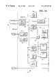
- FIG. 2 is a diagram illustrating further details of master control circuit 15 a, included in the ASIC 12 .
- Master control 15 includes a decode and select control circuit 102 , and leading edge detect and trailing edge detect circuits 104 and 106 , respectively.
- Master control 15 also includes pre-scale register 108 , motor configuration register 110 , multiplexer 112 , motor speed register 114 , laser off register 116 , and laser control 118 , which are connected to decode and select control circuit 102 , and also to data bus 43 .
- master control 15 receives address, control and data inputs from the microprocessor 42 .
- the decode and select control circuit 102 selects one of pre-scale register 108 , motor configuration register 110 , motor speed register 114 , laser off register 116 and laser control 118 in response to address and control signals from the microprocessor 42 .
- Data is simultaneously placed on data bus 43 by microprocessor 42 , and the data is loaded into the selected device.
- Master control 15 also includes a time stamp clock 130 which generates a time stamp value which may up to 14 bits long.
- the time stamp clock 130 is controlled by a clock prescaler 120 .
- the clock prescaler receives a constant clock input, and the rate at which the clock prescaler produces output is controlled by a value stored in the pre-scale register 102 .
- the pre-scale value is set such that the maximum value for bits 0 - 9 is just greater than the time for a full revolution of motor 30 when it is turning at a predetermined minimum speed as discussed further below.
- the clock prescaler supplies a clock input to a time stamp counter 130 , so that the clock of time stamp counter 130 is activated each time the clock prescaler increments.
- Time stamp counter 130 produces a signal TS, the overflow bits 10 - 13 , which is supplied to the A input of a motor speed comparator 126 .
- Motor speed comparator 126 is an A>B comparator, and receives as its B input, data from motor speed register 114 indicating a first predetermined minimum allowable speed of motor 30 .
- the value TS exceeds the value stored in the motor speed register, and, therefore, the A input of comparator 126 exceeds its B input.
- Comparator 126 then produces an interrupt signal to the microprocessor 42 which can respond to this condition. This allows the microprocessor 42 to adjust the speed as desired to address special reading conditions, such as bar codes that are more easily read at slower than normal speeds of rotation.
- Signal TS is also supplied as the A input of laser comparator 128 , an A ⁇ B comparator, which also receives as its B input data from laser off register 116 indicating a second predetermined minimum, the minimum allowable speed for motor 30 at which the laser 29 will be allowed to operate.
- the output of laser comparator 128 is supplied to AND gate 134 , which also receives an input from laser control 118 .
- AND gate 134 provides a laser ON signal, controlling whether the laser 29 is on or off.
- the laser 29 can only operate when laser control 118 commands the laser 29 to be ON, and when the TS value indicates that the speed of motor 30 is within the allowed limits.
- the motor configuration register 110 stores data indicating the number of pulses per revolution and the polarity of the edge to synch on.
- the edge to synch on information is provided to multiplexer 112 which multiplexes the proper edge detect signal from detector 104 or 106 to time stamp counter 130 .
- Pulse comparator 122 receives the number of pulses per revolution and supplies a reset input to clock motor pulse counter 124 and to time stamp counter 130 , and a clock input to motor revolution counter 132 .
- a motor pulse signal is sent to ASIC 12 , which receives it at leading and trailing edge detectors 104 and 106 , respectively.
- Leading and trailing edge detectors 104 and 106 each produce an output which is supplied to multiplexer 112 .
- Multiplexer 112 then supplies an output which is provided to a clock motor pulse counter 124 .
- Clock motor pulse counter 124 counts the input received from multiplexer 112 and supplies the count to a pulse comparator 122 .
- Pulse comparator 122 also receives an input from motor configuration register 110 , the input from motor configuration register 110 indicating the number of pulses in a full revolution.
- the pulse comparator 122 produces a pulse, which resets time stamp counter 130 and clock motor pulse counter 124 , and increments the clock of motor revolution counter 132 .
- Motor revolution counter 132 provides a count MR, which combines with the signal TS from clock time stamp counter to produce the Time Stamp count, which is used as further described below in connection with the discussion of FIG. 3 .
- FIG. 3 is a diagram illustrating the first video circuit 17 in further detail.
- First video circuit 17 is identical to and operates in parallel with second video circuit 19 , which for the sake of simplicity will not be described in detail.
- First video circuit 17 includes interval counter 302 , edge detector 304 , open filter limit register circuit 306 and prebuffer 308 .
- the prebuffer 308 further includes flags prebuffer 308 a and intervals prebuffer shift register 308 b.
- First video circuit 17 further includes Tstamp prebuffer shift register 310 , comparator circuit 312 , interval sums circuit 314 , FIFO control circuit 316 , multiplexer 318 , UPC filter 320 and Interval FIFO circuit 322 .
- the first video circuit 17 receives a video input, which is routed into edge detector 304 .
- Edge detector 304 produces a shift clock output which is supplied to flags prebuffer shift register 308 a and the Tstamp prebuffer shift register 310 .
- the shift clock output is also supplied to the interval counter 302 as a reset input.
- Edge detector 304 causes interval counter 302 to be started on a video transition, a 12-bit signal INT which represents the value and the video polarity of the interval.
- the signal INT is shifted into the intervals prebuffer shift register on the next transition of the video signal, which also resets intervals counter 302 , thus starting the timing of the next interval.
- These intervals represent the time interval or, effectively the width, of the bars and spaces making up a bar code being scanned.
- the Timestamp signal which represents the 10-bit Time Stamp and the 4 least significant bits of the motor revolution counter 132 are shifted into the time stamp prebuffer shift register 310 .
- the time duration of each video interval, the polarity and the time relationship to the motor position are captured for each video transition.
- the video intervals are also sent through interval sum 314 and filter circuit 320 , which determine if the video data stream meets predetermined timing relationships to indicate that the video data stream represents valid bar code data. Further details of presently preferred video processing are provided in U.S. Pat. No. 5,262,625 assigned to the assignee of the present invention and incorporated by reference herein in its entirety. For example, if the time interval between the beginning and end of the video data is too long, the data did not come from a valid scan of a bar code, and will be rejected. The beginning and end of legitimate bar code data are marked by setting flag bits in the flags prebuffer shift register 308 a. The flag bits are then added to the corresponding interval data word stored in intervals prebuffer shift register 308 b.
- the flags are used by the FIFO control 316 to determine which intervals are to be written into the interval FIFO 322 , which buffers the interval data for microprocessor 42 .
- the corresponding Time Stamp value is also written into interval FIFO 322 preceding the interval data word. This is done by passing the Time Stamp signal from the Tstamp prebuffer shift register 310 and the output of prebuffer 308 into multiplexer 318 which operates under control of FIFO control 316 to control whether the Time Stamp or interval data is selectively written into comparator 312 .
- the Time Stamp value is also sent to comparator circuit 312 , where the signal is compared with the contents of the registers in open filter limit register circuit 306 .
- Open filter limit register circuit 306 includes four sets of open filter limit registers in which microprocessor 42 may load time values for comparison with the time stamp values received from the time stamp prebuffer. Microprocessor 42 , in analyzing the interval data read from interval FIFO 322 , may determine that more intervals than are being allowed by digital filter set 320 , are required to properly decode the bar code data. This effectively allows real time control of the filter registers matched to observed scan conditions.
- Microprocessor 42 then computes the time values for adjacent laser scan beams, and loads these limits in one or more of the open filter limit registers in open filter limit register circuit 306 .
- the contents of the registers in open filter limit register 306 are fed to comparator circuit 312 , for comparison to the Timestamp signal.
- comparator circuit 312 sends an open filters signal to FIFO control 316 , causing FIFO control 316 to allow all the following intervals to be written into the internal FIFO 322 so long as this open filters signal is being provided. This signal will override starting or ending flag condition signals from the flags prebuffer 308 a.
- ASIC 12 also includes the second video block 19 , which operates in parallel with the first video block 17 .
- the video blocks 17 and 19 may advantageously be supplied with signal VIDEO 0 and VIDEO 1 processed with different filtering and thresholding in analog video preprocessor 52 .
- the received video signals are thus captured with differently conditioned analog circuitry.
- Proper choice of the filtering used and the processing employed in first video block 17 and second video block 19 gives a wider coverage to the laser signal reflected from the bar code 34 .
- FIG. 4 is a flowchart illustrating a method 400 of detecting time and angular position of an optical assembly used in a bar code scanner according to the principles of the present invention.
- the bar code scanner is started.
- the bar code scanner preferably includes an optical assembly having a rotating portion. This rotating portion of the optical assembly is preferably driven by a motor having an associated pulse producing device.
- the motor is started. A pulse or pulses are produced by the pulse producing device associated with the motor. It will be recognized that any suitable position sensor may be employed.
- a clock is started and the time is monitored.
- clock pulses are counted and a time stamp is generated. Step 408 continues on an ongoing basis. That is, the clock pulses continue to be counted to generate a time stamp so long as the bar code scanner is operating or until the time stamp is reset to zero.
- a scan of a bar code is performed.
- the scan is checked for validity. If the scan is invalid, control is passed to step 414 and the scan is rejected. If the scan is valid, control is passed to step 416 and the time stamp is checked to determine the time of the scan. The time data is then stored.
- the pulse count is recovered from the pulse counter and stored.
- the total angular rotation of the motor from its starting point, corresponding to the synch pulse, that has occurred during the time measured by the time stamp is calculated.
- the time and the associated interval data for an event of interest are combined to produce a combined information block.
- the combined information block is supplied to a microprocessor, and is then used by the microprocessor to improve the accuracy of the scan by reconstructing a bar code from appropriate bar code fragments with timing and position data indicative that they come from the same bar code, or by discriminating between two bar codes read within a shorter than normally acceptable interval.
- the timing and position data can be utilized to provide operator feedback or to achieve other advantages previously discussed above.
Abstract
Description
Claims (18)
Priority Applications (5)
| Application Number | Priority Date | Filing Date | Title |
|---|---|---|---|
| US09/001,369 US6394351B1 (en) | 1997-12-31 | 1997-12-31 | Methods and apparatus for enhanced scanner operation employing bar code and bar code fragment time and position of data collection |
| EP98310606A EP0930578B1 (en) | 1997-12-31 | 1998-12-22 | Timing and scanning mirror position detector for use in a bar code scanner |
| DE69835660T DE69835660T2 (en) | 1997-12-31 | 1998-12-22 | Time and scanning mirror location detector for a bar code scanner |
| JP36962098A JP4491082B2 (en) | 1997-12-31 | 1998-12-25 | Barcode scanner |
| US10/120,916 US6695211B2 (en) | 1997-12-31 | 2002-04-11 | Methods and apparatus for enhanced scanner operation employing bar code and bar code fragment time and position of data collection |
Applications Claiming Priority (1)
| Application Number | Priority Date | Filing Date | Title |
|---|---|---|---|
| US09/001,369 US6394351B1 (en) | 1997-12-31 | 1997-12-31 | Methods and apparatus for enhanced scanner operation employing bar code and bar code fragment time and position of data collection |
Related Child Applications (1)
| Application Number | Title | Priority Date | Filing Date |
|---|---|---|---|
| US10/120,916 Continuation US6695211B2 (en) | 1997-12-31 | 2002-04-11 | Methods and apparatus for enhanced scanner operation employing bar code and bar code fragment time and position of data collection |
Publications (1)
| Publication Number | Publication Date |
|---|---|
| US6394351B1 true US6394351B1 (en) | 2002-05-28 |
Family
ID=21695696
Family Applications (2)
| Application Number | Title | Priority Date | Filing Date |
|---|---|---|---|
| US09/001,369 Expired - Lifetime US6394351B1 (en) | 1997-12-31 | 1997-12-31 | Methods and apparatus for enhanced scanner operation employing bar code and bar code fragment time and position of data collection |
| US10/120,916 Expired - Lifetime US6695211B2 (en) | 1997-12-31 | 2002-04-11 | Methods and apparatus for enhanced scanner operation employing bar code and bar code fragment time and position of data collection |
Family Applications After (1)
| Application Number | Title | Priority Date | Filing Date |
|---|---|---|---|
| US10/120,916 Expired - Lifetime US6695211B2 (en) | 1997-12-31 | 2002-04-11 | Methods and apparatus for enhanced scanner operation employing bar code and bar code fragment time and position of data collection |
Country Status (4)
| Country | Link |
|---|---|
| US (2) | US6394351B1 (en) |
| EP (1) | EP0930578B1 (en) |
| JP (1) | JP4491082B2 (en) |
| DE (1) | DE69835660T2 (en) |
Cited By (13)
| Publication number | Priority date | Publication date | Assignee | Title |
|---|---|---|---|---|
| US20020185538A1 (en) * | 2001-06-11 | 2002-12-12 | Ncr Corporation | Methods and apparatus for determining a position of a rotating optical element in a bar code scanner |
| US6497366B1 (en) * | 1997-12-31 | 2002-12-24 | Ncr Corporation | Methods and apparatus for dual channel video recovery in bar code scanners |
| US6695211B2 (en) * | 1997-12-31 | 2004-02-24 | Ncr Corporation | Methods and apparatus for enhanced scanner operation employing bar code and bar code fragment time and position of data collection |
| US20040155107A1 (en) * | 2001-07-12 | 2004-08-12 | Psc Scanning, Inc. | Method and apparatus to prevent reporting multiple reads of optical coded items |
| US20050035315A1 (en) * | 1999-12-01 | 2005-02-17 | Paul Lapstun | Viewer configured to display, and method of displaying, information on a display to at least partially take into account a position of the viewer relative to a surface |
| US6874688B1 (en) * | 2004-03-22 | 2005-04-05 | Symbol Technologies, Inc. | Data collection signal processing for increased performance in electro-optical readers |
| US20050092834A1 (en) * | 2000-10-17 | 2005-05-05 | Psc Scanning, Inc. | System and method for training and monitoring data reader operators |
| US20070152061A1 (en) * | 2005-12-29 | 2007-07-05 | Ncr Corporation | Methods and apparatus for tracking the direction of a moving item by a bar code scanner |
| US20080121717A1 (en) * | 2006-09-21 | 2008-05-29 | Gregerson David L | Barcode scanner with configurable video modes |
| US8270303B2 (en) | 2007-12-21 | 2012-09-18 | Hand Held Products, Inc. | Using metadata tags in video recordings produced by portable encoded information reading terminals |
| US8939369B2 (en) | 2011-01-24 | 2015-01-27 | Datalogic ADC, Inc. | Exception detection and handling in automated optical code reading systems |
| US20150144692A1 (en) * | 2013-11-22 | 2015-05-28 | Hand Held Products, Inc. | System and method for indicia reading and verification |
| US10942964B2 (en) | 2009-02-02 | 2021-03-09 | Hand Held Products, Inc. | Apparatus and method of embedding meta-data in a captured image |
Families Citing this family (3)
| Publication number | Priority date | Publication date | Assignee | Title |
|---|---|---|---|---|
| US8226007B2 (en) * | 2007-03-23 | 2012-07-24 | Ltt, Ltd | Method and apparatus for using a limited capacity portable data carrier |
| US20130077641A1 (en) * | 2011-09-22 | 2013-03-28 | Harley F. Burger, Jr. | Systems, Circuits and Methods for Time Stamp Based One-Way Communications |
| US20130204689A1 (en) * | 2012-02-02 | 2013-08-08 | R-Evolution Industries Llc | Controlled distribution of digital payloads |
Citations (14)
| Publication number | Priority date | Publication date | Assignee | Title |
|---|---|---|---|---|
| US4409469A (en) * | 1980-01-21 | 1983-10-11 | Sharp Kabushiki Kaisha | Optical bar code reader |
| US5004916A (en) * | 1989-07-28 | 1991-04-02 | Ncr Corporation | Scanning system having automatic laser shutdown upon detection of defective scanning element motion |
| US5013899A (en) * | 1989-07-28 | 1991-05-07 | Ncr Corporation | Scanning system having low quiescent current scanning mirror motor driver circuitry |
| US5278397A (en) | 1991-07-25 | 1994-01-11 | Symbol Technologies, Inc. | Multi-resolution bar code reader |
| US5332892A (en) | 1991-07-25 | 1994-07-26 | Symbol Technologies, Inc. | Optical systems for bar code scanners |
| US5357094A (en) | 1990-12-21 | 1994-10-18 | Minnesota Mining And Manufacturing Company | Two-channel XOR bar code and optical reader |
| US5365048A (en) * | 1992-02-20 | 1994-11-15 | Olympus Optical Co., Ltd. | Bar code symbol reading apparatus with double-reading preventing function |
| US5404002A (en) | 1993-05-17 | 1995-04-04 | At&T Global Information Solutions Company | Backup method for multiple source optical scanner |
| JPH07282177A (en) * | 1994-04-06 | 1995-10-27 | Omron Corp | Bar code reader |
| US5552592A (en) | 1989-10-30 | 1996-09-03 | Symbol Technologies, Inc. | Slim scan module with dual detectors |
| US5663552A (en) * | 1993-10-19 | 1997-09-02 | Matsushita Electric Industrial Co., Ltd. | Portable information terminal apparatus having image processing function |
| US5742042A (en) * | 1994-09-26 | 1998-04-21 | Allen-Bradley Company, Inc. | Bar code reader having a position sensor in communication with a raster mirror |
| US5898163A (en) * | 1996-02-07 | 1999-04-27 | Fujitsu Limited | Optical code reader and process for reading optical codes |
| US6032865A (en) * | 1997-01-31 | 2000-03-07 | Fujitsu Limited | Method of reading bar code |
Family Cites Families (16)
| Publication number | Priority date | Publication date | Assignee | Title |
|---|---|---|---|---|
| US4800256A (en) * | 1986-12-08 | 1989-01-24 | International Business Machines Corporation | Halographic scanner having adjustable sampling rate |
| JP2718240B2 (en) * | 1990-03-20 | 1998-02-25 | 富士通株式会社 | Reader |
| JPH0512480A (en) * | 1991-07-05 | 1993-01-22 | Nec Corp | Bar code reader |
| US5361158A (en) * | 1992-09-14 | 1994-11-01 | At&T Global Information Solutions (Fka Ncr Corporation) | Multiple source optical scanner |
| JPH06162249A (en) * | 1992-09-28 | 1994-06-10 | Nippondenso Co Ltd | Optical information reader |
| JPH0798473A (en) * | 1993-05-10 | 1995-04-11 | Olympus Optical Co Ltd | Camera shake amount detecting device for camera |
| JPH07141458A (en) * | 1993-11-19 | 1995-06-02 | Fujitsu Kiden Ltd | Multi-stage bar code reading system |
| JPH07200714A (en) * | 1993-12-28 | 1995-08-04 | Nec Corp | Optical symbol reader |
| JPH07319989A (en) * | 1994-05-25 | 1995-12-08 | Sumitomo Electric Ind Ltd | Optical mark reader |
| US5484995A (en) * | 1994-09-26 | 1996-01-16 | Allen-Bradley Company, Inc. | Pulse drive circuit for bar code reader resonant oscillator |
| JPH0991368A (en) * | 1995-07-20 | 1997-04-04 | Fujitsu Ltd | Optical reader |
| US5633488A (en) * | 1995-12-19 | 1997-05-27 | Webscan, Inc. | Method and apparatus to enable the high speed evaluation of bar code indicia |
| JP3526370B2 (en) * | 1996-05-29 | 2004-05-10 | 株式会社東芝 | Barcode reading method and barcode reader |
| US5988505A (en) * | 1996-06-03 | 1999-11-23 | Symbol Technologies, Inc. | Omnidirectional reading of two-dimensional symbols |
| US6394351B1 (en) * | 1997-12-31 | 2002-05-28 | Ncr Corporation | Methods and apparatus for enhanced scanner operation employing bar code and bar code fragment time and position of data collection |
| JP2000035547A (en) * | 1998-07-17 | 2000-02-02 | Fujitsu Ltd | Optical reader having tiltable stage for placing optical unit |
-
1997
- 1997-12-31 US US09/001,369 patent/US6394351B1/en not_active Expired - Lifetime
-
1998
- 1998-12-22 DE DE69835660T patent/DE69835660T2/en not_active Expired - Lifetime
- 1998-12-22 EP EP98310606A patent/EP0930578B1/en not_active Expired - Lifetime
- 1998-12-25 JP JP36962098A patent/JP4491082B2/en not_active Expired - Lifetime
-
2002
- 2002-04-11 US US10/120,916 patent/US6695211B2/en not_active Expired - Lifetime
Patent Citations (15)
| Publication number | Priority date | Publication date | Assignee | Title |
|---|---|---|---|---|
| US4409469A (en) * | 1980-01-21 | 1983-10-11 | Sharp Kabushiki Kaisha | Optical bar code reader |
| US5004916A (en) * | 1989-07-28 | 1991-04-02 | Ncr Corporation | Scanning system having automatic laser shutdown upon detection of defective scanning element motion |
| US5013899A (en) * | 1989-07-28 | 1991-05-07 | Ncr Corporation | Scanning system having low quiescent current scanning mirror motor driver circuitry |
| US5552592A (en) | 1989-10-30 | 1996-09-03 | Symbol Technologies, Inc. | Slim scan module with dual detectors |
| US5357094A (en) | 1990-12-21 | 1994-10-18 | Minnesota Mining And Manufacturing Company | Two-channel XOR bar code and optical reader |
| US5506392A (en) | 1991-07-25 | 1996-04-09 | Symbol Technologies, Inc. | Photodetector for use in reading optical information symbols |
| US5332892A (en) | 1991-07-25 | 1994-07-26 | Symbol Technologies, Inc. | Optical systems for bar code scanners |
| US5278397A (en) | 1991-07-25 | 1994-01-11 | Symbol Technologies, Inc. | Multi-resolution bar code reader |
| US5365048A (en) * | 1992-02-20 | 1994-11-15 | Olympus Optical Co., Ltd. | Bar code symbol reading apparatus with double-reading preventing function |
| US5404002A (en) | 1993-05-17 | 1995-04-04 | At&T Global Information Solutions Company | Backup method for multiple source optical scanner |
| US5663552A (en) * | 1993-10-19 | 1997-09-02 | Matsushita Electric Industrial Co., Ltd. | Portable information terminal apparatus having image processing function |
| JPH07282177A (en) * | 1994-04-06 | 1995-10-27 | Omron Corp | Bar code reader |
| US5742042A (en) * | 1994-09-26 | 1998-04-21 | Allen-Bradley Company, Inc. | Bar code reader having a position sensor in communication with a raster mirror |
| US5898163A (en) * | 1996-02-07 | 1999-04-27 | Fujitsu Limited | Optical code reader and process for reading optical codes |
| US6032865A (en) * | 1997-01-31 | 2000-03-07 | Fujitsu Limited | Method of reading bar code |
Cited By (29)
| Publication number | Priority date | Publication date | Assignee | Title |
|---|---|---|---|---|
| US6497366B1 (en) * | 1997-12-31 | 2002-12-24 | Ncr Corporation | Methods and apparatus for dual channel video recovery in bar code scanners |
| US6695211B2 (en) * | 1997-12-31 | 2004-02-24 | Ncr Corporation | Methods and apparatus for enhanced scanner operation employing bar code and bar code fragment time and position of data collection |
| US20050145807A1 (en) * | 1999-12-01 | 2005-07-07 | Paul Lapstun | Device for interacting with an interface surface |
| US7671334B2 (en) | 1999-12-01 | 2010-03-02 | Silverbrook Research Pty Ltd | Viewing device for use with coded data on a surface |
| US20080237348A1 (en) * | 1999-12-01 | 2008-10-02 | Silverbrook Research Pty Ltd | Viewing Device For Use With Coded Data On A Surface |
| US20050035315A1 (en) * | 1999-12-01 | 2005-02-17 | Paul Lapstun | Viewer configured to display, and method of displaying, information on a display to at least partially take into account a position of the viewer relative to a surface |
| US7148499B2 (en) | 1999-12-01 | 2006-12-12 | Silverbrook Research Pty Ltd | Device for interacting with an interface surface |
| US7019319B2 (en) | 1999-12-01 | 2006-03-28 | Silverbrook Research Pty Ltd | Viewer configured to display, and method of displaying, information on a display to at least partially take into account a position of the viewer relative to a surface |
| US20050092834A1 (en) * | 2000-10-17 | 2005-05-05 | Psc Scanning, Inc. | System and method for training and monitoring data reader operators |
| US20080164309A1 (en) * | 2000-10-17 | 2008-07-10 | Datalogic Scanning, Inc. | System and method for training and monitoring data reader operators |
| US7562817B2 (en) | 2000-10-17 | 2009-07-21 | Datalogic Scanning, Inc. | System and method for training and monitoring data reader operators |
| US7407096B2 (en) | 2000-10-17 | 2008-08-05 | Datalogic Scanning, Inc. | System and method for training and monitoring data reader operators |
| US20020185538A1 (en) * | 2001-06-11 | 2002-12-12 | Ncr Corporation | Methods and apparatus for determining a position of a rotating optical element in a bar code scanner |
| US6827271B2 (en) * | 2001-06-11 | 2004-12-07 | Ncr Corporation | Methods and apparatus for determining a position of a rotating optical element in a bar code scanner |
| US6932273B2 (en) | 2001-07-12 | 2005-08-23 | Psc Scanning, Inc. | Method and apparatus to prevent reporting multiple reads of optical coded items |
| US20040155107A1 (en) * | 2001-07-12 | 2004-08-12 | Psc Scanning, Inc. | Method and apparatus to prevent reporting multiple reads of optical coded items |
| AU2005226045B2 (en) * | 2004-03-22 | 2010-10-14 | Symbol Technologies, Llc. | Data collection signal processing for increased performance in electro-optical readers |
| GB2429281B (en) * | 2004-03-22 | 2007-08-08 | Symbol Technologies Inc | Data collection signal processing for increased performance in electro-optical readers |
| GB2429281A (en) * | 2004-03-22 | 2007-02-21 | Symbol Technologies Inc | Data collection signal processing for increased performance in electro-optical readers |
| US6874688B1 (en) * | 2004-03-22 | 2005-04-05 | Symbol Technologies, Inc. | Data collection signal processing for increased performance in electro-optical readers |
| WO2005093492A1 (en) * | 2004-03-22 | 2005-10-06 | Symbol Technologies, Inc. | Data collection signal processing for increased performance in electro-optical readers |
| US7389923B2 (en) * | 2005-12-29 | 2008-06-24 | Ncr Corporation | Methods and apparatus for tracking the direction of a moving item by a bar code scanner |
| US20070152061A1 (en) * | 2005-12-29 | 2007-07-05 | Ncr Corporation | Methods and apparatus for tracking the direction of a moving item by a bar code scanner |
| US7380719B1 (en) * | 2006-09-21 | 2008-06-03 | Ncr Corporation | Barcode scanner with configurable video modes |
| US20080121717A1 (en) * | 2006-09-21 | 2008-05-29 | Gregerson David L | Barcode scanner with configurable video modes |
| US8270303B2 (en) | 2007-12-21 | 2012-09-18 | Hand Held Products, Inc. | Using metadata tags in video recordings produced by portable encoded information reading terminals |
| US10942964B2 (en) | 2009-02-02 | 2021-03-09 | Hand Held Products, Inc. | Apparatus and method of embedding meta-data in a captured image |
| US8939369B2 (en) | 2011-01-24 | 2015-01-27 | Datalogic ADC, Inc. | Exception detection and handling in automated optical code reading systems |
| US20150144692A1 (en) * | 2013-11-22 | 2015-05-28 | Hand Held Products, Inc. | System and method for indicia reading and verification |
Also Published As
| Publication number | Publication date |
|---|---|
| US20020117548A1 (en) | 2002-08-29 |
| JP4491082B2 (en) | 2010-06-30 |
| EP0930578B1 (en) | 2006-08-23 |
| DE69835660T2 (en) | 2007-09-20 |
| DE69835660D1 (en) | 2006-10-05 |
| JPH11250170A (en) | 1999-09-17 |
| US6695211B2 (en) | 2004-02-24 |
| EP0930578A2 (en) | 1999-07-21 |
| EP0930578A3 (en) | 2003-05-28 |
Similar Documents
| Publication | Publication Date | Title |
|---|---|---|
| US6394351B1 (en) | Methods and apparatus for enhanced scanner operation employing bar code and bar code fragment time and position of data collection | |
| EP1806680B1 (en) | Method and apparatus for tracking the direction of a moving item by a bar code scanner | |
| US7492973B2 (en) | Apparatus and method for determining whether machine readable information on an item matches the item | |
| US4431912A (en) | Method for controlling the operation of an optical scanner | |
| US8245926B2 (en) | Method of preventing multiple reads when scanning groups of optical codes | |
| US6827266B2 (en) | Methods and apparatus for using imaging information to improve scanning accuracy in bar code scanners | |
| US3868634A (en) | Reading of contrasting data by means of continuously attempting to decode read signals | |
| US3964022A (en) | Hand-held scan data handling system | |
| US20090272810A1 (en) | Bar code reader having multiple cameras | |
| US7108187B2 (en) | Method of reading a plurality of bar codes during a scanning motion | |
| US6220513B1 (en) | Methods and apparatus for determining bar code label location information | |
| JPH0246986B2 (en) | ||
| JP4339433B2 (en) | Data recovery apparatus and method for bar code scanner | |
| WO1989012868A1 (en) | Method and apparatus for reading characters | |
| JP2000268291A (en) | License plate recognition device | |
| US7549585B2 (en) | Methods and apparatus for preventing improper scans by a bar code scanner | |
| US5988507A (en) | Bar code reader | |
| JPS5844578A (en) | Deciding device for writing direction of address information | |
| JP2751641B2 (en) | Barcode reader | |
| JPH04164279A (en) | Sif target detection method | |
| JP2002352185A (en) | Barcode reader |
Legal Events
| Date | Code | Title | Description |
|---|---|---|---|
| AS | Assignment |
Owner name: NCR CORPORATION, OHIO Free format text: ASSIGNMENT OF ASSIGNORS INTEREST;ASSIGNORS:KEYS, JOHN B.;BLANFORD, DENIS M.;FABIAN, KENNETH J.;AND OTHERS;REEL/FRAME:009192/0963 Effective date: 19980305 |
|
| STCF | Information on status: patent grant |
Free format text: PATENTED CASE |
|
| FPAY | Fee payment |
Year of fee payment: 4 |
|
| FPAY | Fee payment |
Year of fee payment: 8 |
|
| FPAY | Fee payment |
Year of fee payment: 12 |
|
| AS | Assignment |
Owner name: JPMORGAN CHASE BANK, N.A., AS ADMINISTRATIVE AGENT, ILLINOIS Free format text: SECURITY AGREEMENT;ASSIGNORS:NCR CORPORATION;NCR INTERNATIONAL, INC.;REEL/FRAME:032034/0010 Effective date: 20140106 Owner name: JPMORGAN CHASE BANK, N.A., AS ADMINISTRATIVE AGENT Free format text: SECURITY AGREEMENT;ASSIGNORS:NCR CORPORATION;NCR INTERNATIONAL, INC.;REEL/FRAME:032034/0010 Effective date: 20140106 |
|
| AS | Assignment |
Owner name: JPMORGAN CHASE BANK, N.A., ILLINOIS Free format text: SECURITY AGREEMENT;ASSIGNORS:NCR CORPORATION;NCR INTERNATIONAL, INC.;REEL/FRAME:038646/0001 Effective date: 20160331 |
|
| AS | Assignment |
Owner name: NCR VOYIX CORPORATION, GEORGIA Free format text: RELEASE OF PATENT SECURITY INTEREST;ASSIGNOR:JPMORGAN CHASE BANK, N.A., AS ADMINISTRATIVE AGENT;REEL/FRAME:065346/0531 Effective date: 20231016 Owner name: BANK OF AMERICA, N.A., AS ADMINISTRATIVE AGENT, NORTH CAROLINA Free format text: SECURITY INTEREST;ASSIGNOR:NCR VOYIX CORPORATION;REEL/FRAME:065346/0168 Effective date: 20231016 |
|
| AS | Assignment |
Owner name: NCR VOYIX CORPORATION, GEORGIA Free format text: CHANGE OF NAME;ASSIGNOR:NCR CORPORATION;REEL/FRAME:065820/0704 Effective date: 20231013 |