US6347963B1 - Interchangeable backplane interface connection panel - Google Patents
Interchangeable backplane interface connection panel Download PDFInfo
- Publication number
- US6347963B1 US6347963B1 US09/470,261 US47026199A US6347963B1 US 6347963 B1 US6347963 B1 US 6347963B1 US 47026199 A US47026199 A US 47026199A US 6347963 B1 US6347963 B1 US 6347963B1
- Authority
- US
- United States
- Prior art keywords
- connectors
- backplane
- cable
- panel
- external
- Prior art date
- Legal status (The legal status is an assumption and is not a legal conclusion. Google has not performed a legal analysis and makes no representation as to the accuracy of the status listed.)
- Expired - Lifetime
Links
Images


Classifications
-
- H—ELECTRICITY
- H01—ELECTRIC ELEMENTS
- H01R—ELECTRICALLY-CONDUCTIVE CONNECTIONS; STRUCTURAL ASSOCIATIONS OF A PLURALITY OF MUTUALLY-INSULATED ELECTRICAL CONNECTING ELEMENTS; COUPLING DEVICES; CURRENT COLLECTORS
- H01R12/00—Structural associations of a plurality of mutually-insulated electrical connecting elements, specially adapted for printed circuits, e.g. printed circuit boards [PCB], flat or ribbon cables, or like generally planar structures, e.g. terminal strips, terminal blocks; Coupling devices specially adapted for printed circuits, flat or ribbon cables, or like generally planar structures; Terminals specially adapted for contact with, or insertion into, printed circuits, flat or ribbon cables, or like generally planar structures
- H01R12/70—Coupling devices
- H01R12/7088—Arrangements for power supply
Landscapes
- Structure Of Telephone Exchanges (AREA)
Abstract
A system and method for converting the numerous quantities, types, and arrangements of plug-in card connectors, usually disposed on the backplane of equipment systems, to an orderly and standardized array of external connectors. The external connectors facilitate the electrical connection between the cards and one of a variety of specific external cable connectors.
Description
Most modem equipment for implementing telecommunications systems contain one or more electronic apparatus housed in a casing. The casing is generally enclosed, with a front access door, sidewalls, and a backplane forming the casing. Generally, the electronic apparatus is located within the casing and is electrically coupled to the backplane. In most instances, the backplane performs an interconnect function between the various electronic apparatuses within the casing. The backplane also typically supports connectors, which allows an electrical connection to be made between the electronic apparatuses coupled to the backplane and external cables, wires and leads located outside the casing.
Such connectors are typically included in the above-described electronic apparatuses which may be in the form of, e.g., plug-in cards. Different manufacturers and/or distributors of plug-in cards often do not employ uniformity in the types of connectors supported on the cards. Thus, when cards are replaced in telecommunication systems, either due to failure or because of an upgrade, it is not uncommon to find that the connectors on the new cards are no longer compatible with connectors on external cables previously used with the replaced cards.
Moreover, when a plug-in card is added to the backplane, a person adding the card (also called installer) must find space for the connectors on the added card, such that one or more connectors do not interfere with the functioning of the backplane. Since most backplanes are not designed to accommodate multiple connectors, installers usually locate the connectors on fringe areas of the backplane or else on a new backplane, subsequently added to the system.
In accordance with the present invention, a system and method convert the numerous quantities, types, and arrangements of plug-in card connectors usually disposed on the backplane of telecommunication systems to an orderly and standardized array of external connectors. The external connectors facilitate electrical connection between cards in a casing and one of a number of predetermined cable connectors of cables external to the casing.
As described in greater detail below, one or more electronic apparatuses, such as modules, PCAs, PCBs, video cards, audio cards, ethernet cards, or other types of plug-in cards, may be electrically coupled to a first side (also called “internal face”) of the backplane. On the opposite or second side (also called “external face”) of the backplane, a standardized arrangement of connectors, (e.g., pin-type connectors) are provided. The internal face of the backplane has connectors (also called “card connectors”) that receive the variety of plug-in cards. The backplane routes a signal path from the card connectors to the standardized arrangement of connectors (also called “cable connectors”) on the external face.
One embodiment of the system provides a conversion panel. The conversion panel has a first side (also called “internal face”) having a standardized connector arrangement configured to mate with the cable connectors on the external face of the backplane. On the second side (also called “external face”) of the panel, another set of external connectors (also called “cable connectors”) is provided. The external connectors on the conversional panel are different from the cable connectors on the backplane, e.g., one of a variety of connectors suitable for a specific application, such as SMB, BNC, RJ-45, SMB-WW and BNC-WW module, screw terminal block, coaxial F, and champ connectors. The system includes the ability to remove and replace the conversion panel, as needed or desired, such that the type, quantity and/or arrangement of cable connectors on an external face of the casing may be changed.
In one embodiment of the present invention, a system is provided which provides a standardized electrical connection to a backplane of a card-based equipment system. The system includes a main chassis which defines an interior space for receiving plug-in cards. Also included is a backplane, which has a first side and a second side. The first side of the backplane has a plurality of plug-in card sockets for engaging with the plug-in cards. The second side of the backplane has an arrangement of backplane connectors. An interchangeable connection panel is also provided, which has a front side and a back side. The front side of the panel has panel connector receptacles configured to mate with the backplane connectors. The back side of the panel has a plurality of external connectors for establishing an electrical connection to an external cable.
In yet another embodiment of the present invention, a method is provided for standardizing an electrical connection interface of a card based equipment system, which includes coupling a conversion panel to a backplane connector array having different types of connectors, where the conversion panel has a plurality of external connectors for establishing an electrical connection to an external cable.
FIG. 1 shows a telecommunications equipment system chassis in accordance with the present invention;
FIG. 2A is a simplified view of an external face of an embodiment of a backplane in accordance with the present invention;
FIG. 2B is a simplified view of an internal face of the backplane in accordance with the present invention;
FIG. 2C is a simplified illustration of the backplane of FIG. 2A with a protective cover thereon;
FIGS. 3A and 3B are simplified illustrations of an internal view and external view, respectively, of the interchangeable connection panel of the present invention;
FIG. 3C is a simplified illustration of a faceplate according to an embodiment of the present invention;
FIG. 4 is a simplified schematic illustration of the operational configuration of components of the present invention;
FIGS. 5A and 5B, are simplified schematic illustrations of a specific embodiment of the present invention;
FIGS. 6A and 6B, are simplified schematic illustrations of another specific embodiment of the present invention; and
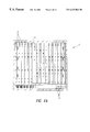
FIGS. 7A and 7B, are simplified schematic illustrations of another specific embodiment of the present invention.
FIG. 1 illustrates a telecommunications equipment system 10, which includes a casing or main chassis 12. Chassis 12 includes several components, such as top wall 14, a bottom wall 16, a side wall 18, a side wall 20, a back wall 22, and a front access door 24. Depending on the embodiment, chassis 12 may have mounting fixtures 26 and 28 located on the side walls 18 and 20 of chassis 12 to facilitate the mounting of system 10. Chassis 12 and mounting fixtures 26 and 28 may be made with sheet metal, injection molded plastic, or other similarly suited structural materials.
On an external face 40 (FIG. 2B) of backplane 32, an array of connectors (hereinafter “backplane connectors”) 42A-42M (wherein A≦J≦M; M being the total number of backplane connectors) are provided. Backplane connectors 42 may be provided in any quantity, and in any manner that does not interfere with the operation of backplane 32. The useable space for connectors on backplane 32 is typically very limited, thus, in a preferred embodiment, backplane connectors 42 are arranged in a predetermined layout on external face 40, such as that shown in FIG. 2B. The predetermined layout includes all connectors 42A-42M arranged in three groupings 44, 48 and 52. Each group may include up to six connectors, but optionally, may have more or less as the useable space permits and/or as the application of the equipment may dictate. In one embodiment, first group 44 and second group 48 include six connectors each. In this embodiment, groups 44 and 48 are positioned proximate to top edge 46 and bottom edge 50, respectively, with group 52 located in a central region of external face 40 (between groups 44 and 48). The backplane connectors of group 44 and group 48 may be any suitable connector, such as pin and card edge connectors. Preferably, but not necessarily, the connectors in groups 44 and 48 are pin-type connectors. The number of pins in each connector 42M may vary depending on, but may include 60-, 85-, 125-, and staggered 125-pins. In one embodiment, group 52 includes four backplane connectors. The backplane connectors of group 52 may be any suitable connector, such as pin and card edge connectors, but preferably (but not necessarily) are staggered 125-pin type connectors. Pin connectors, like those described above, are manufactured by, and commercially available from AMP Incorporated, of Harrisburg, Pa.
As shown in FIG. 2C, when backplane connectors 42 of backplane 32 are not being used, a cover 54 may be installed over backplane 32 to provide protection to the backplane and the user.
Although, the type, arrangement, and quantity of backplane connectors 42 in each of groups 44, 48 and 52 may be variable, in accordance with the present invention, a corresponding type, arrangement, and quantity of mating connectors are provided on one face of a conversion panel 60 (illustrated in FIGS. 3A-3C). A first side 64 (FIG. 3A) of interchangeable conversion panel 60 has an array of connectors 62A-62M which correspond to and are connectable to backplane connectors 42A-42M on backplane 32. Panel 60 may be manufactured as a printed circuit board, of a type well-known in the telecommunications arts, which provides electrical characteristics, including providing an electrical path or route for signals from/to panel connectors 62 to/from external connectors 68.
A second side 66 (FIG. 3B) of conversion panel 60 has connectors 68A-68P which may be arranged in any manner on second side 66, but are generally arranged in columns and rows. Connectors 68 may be any conventional connectors suitable for telecommunications and/or similar functionality. Preferably, connectors 68 may include SMB, BNC, RJ-45, SMB to WireWrap module, screw terminal block, coaxial F, and champ connectors. As shown in FIG. 3C, a faceplate 70 may be optionally placed over, and conventionally secured to, panel 60, with connectors 68A-68P passing through appropriately placed holes provided thereon. Faceplate 70 provides protection to panel 60 and may include labels and other visual graphics for directing the user in proper connection procedures. Faceplate 70 may also have a handle 71 to facilitate the mounting and/or removal of the interchangeable connection panel.
In one example, plug-in card 72 (FIG. 4) is removably attached to internal face 73 of backplane 74, which includes sockets 76 configured to engage and mate with card connectors 78 to establish an electrical connection therebetween. On external face 80 of backplane 74, pin-connectors 82 are provided of a type and in an array suitable for engaging corresponding connectors 84 provided on conversion panel 86. Connectors 82 and 84 will be collectively referred to as internal connectors 82 and 84. Panel 86 has an external face 88 which is capable of supporting different types of external connectors 90, such as SMB, BNC, RJ-45, SMB-WW module, screw terminal block, coaxial F, and champ connectors. Cable connectors 92 connected to the end of cables, wires or twisted wire pairs, may then be coupled to external connectors 90.
In one embodiment, panel 102 (FIG. 5A) is coupled on a first side to backplane 32 (not shown in FIG. 5A) and supports thereon SMB type connectors 104. In this example, panel 102 only covers a portion of backplane 32 (e.g., only the right half). Panel 102 may then be covered by an SMB faceplate 106. Another panel 108, which provides an interface for alarm signals, may be used to cover a lower portion of the rear of the equipment. Optionally, as shown in FIG. 5B, a left-side panel 110 and a left-side faceplate 112 may be used instead of, or in conjunction with, the right-side panel 102 and faceplate 106.
In another embodiment, a conversion panel 114 (FIG. 6A) is coupled on a first side to backplane 32 and supports thereon BNC type connectors 116 instead of SMB type connectors 104 described above in reference to FIGS. 5A and 5B. In all other respects, the embodiment illustrated in FIGS. 6A and 6B is identical to the embodiment illustrated in FIGS. 5A and 5B.
In yet another embodiment, another conversion panel 92 includes multiple champ connectors 124 (FIG. 7A) coupled to the backplane 32 (not shown in FIG. 7A). Specifically, champ connectors 124 may be coupled together, side-by-side, to form a single panel 92, which may then be coupled to backplane connectors 42. Optionally, champ connectors 124 may individually be coupled to individual columns of backplane connectors 42 (FIG. 2B). As shown in FIG. 7B, multiple left-side champ connectors 126 may be used instead of, or in conjunction with, the right-side champ connectors 124. Champ connectors, SMB connectors, and BNC connectors, are all available from AMP Incorporated of Harrisburg, Pa.
Although particular embodiments of the invention have been illustrated and described, modifications and changes will be apparent to those of skill in the art. For example, as different types of plug-in cards continue to evolve, which may require different external connectors than those mentioned above, it is intended to be within the scope of present invention to include all types of external connectors. Such modifications and adaptations of the various embodiments, implementations and examples described herein are encompassed by the attached claims.
Claims (19)
1. A system for standardizing an electrical connection interface, said system comprising:
a main chassis;
a backplane mounted to said main chassis and having a plurality of backplane connectors of varying configurations; and
a panel including first and second opposing sides, said first side having a first plurality of connectors of varying configurations mated with each of said plurality of backplane connectors of varying configurations, said second side having a second plurality of connectors for establishing an electrical connection to an external cable.
2. The system of claim 1 , wherein said main chassis defines an interior space for receiving plug-in cards which provide a telecommunications functionality.
3. The system of claim 1 , wherein said main chassis defines an interior space for receiving plug-in cards, said plug-in cards taken from the group consisting of DS1, DS3, ethernet, and video cards.
4. The system of claim 1 , wherein said external cable is selected from the group consisting of optical fiber cable, electrical cable, coaxial cable, ribbon cable, and twisted wire pair cable.
5. The system of claim 1 , further comprising a faceplate mountable over said second side of said panel.
6. The system of claim 1 , wherein said plurality of backplane connectors of varying configurations comprise a combination of pin-type connectors taken from the group consisting of 60-pin, 85-pin, 125-pin, and staggered 125-pin connectors.
7. The system of claim 1 , wherein said second plurality of connectors are taken from the group consisting of SMB, BNC, RJ-45, SMB-WW modules, screw terminal block, coaxial F, and champ connectors.
8. The system of claim 1 , wherein said main chassis comprises a door for enclosing said main chassis at the front.
9. The system of claim 1 , further comprising mounting fixtures coupled to each side of said main chassis to facilitate mounting of said main chassis.
10. The system of claim 1 , further comprising a protective panel for covering said backplane when said backplane is not in use.
11. The system of claim 1 , wherein said panel is mountable to either a left- or right-hand side of said backplane.
12. A system for standardizing an electrical connection interface, said system comprising:
a chassis;
a backplane having a plurality of backplane connectors of varying configurations, said backplane mounted on said chassis; and
means mounted to said backplane to convert said plurality of backplane connectors of varying configurations to an array of a single configuration of external connectors.
13. The system of claim 12 , wherein said means for converting comprises an interchangeable panel having a front side and a back side, said front side having connector receptacles for mating with said plurality of backplane connectors of varying configurations, said back side having said array of a single configuration of external connectors.
14. The system of claim 12 , wherein said plurality of backplane connectors of varying configurations comprises a combination of at least two different connectors taken form the group consisting of a 60-pin connector, an 85-pin connector, a 125-pin connector, and a staggered 125-pin connector.
15. The system of claim 12 , wherein said main chassis defines an interior space for receiving plug-in cards, said plug-in cards taken from the group consisting of DS1, DS3, ethernet, and video cards.
16. The system of claim 12 , wherein said external connectors are taken from the group consisting of SMB, BNC, RJ-45, SMB-WW modules, screw terminal block, coaxial F, and champ connectors.
17. A method for standardizing an electrical connection interface, said method comprising:
providing a backplane including a backplane connector array;
mounting a conversion panel having a first combination of different configurations of panel connectors to said backplane connector array including a second combination of different configuration of backplane connectors corresponding to each of said panel connectors, said conversion panel having a plurality of external connectors for establishing an electrical connection to at least one external cable.
18. A method as in claim 17 , wherein said external connectors are taken from the group consisting of SMB, BNC, RJ-45, SMB-WW modules, screw terminal block, coaxial F, and champ connectors.
19. The method of claim 17 , wherein said external cable is selected from the group consisting of optical fiber cable, electrical cable, coaxial cable, ribbon cable, and twisted wire pair cable.
Priority Applications (1)
| Application Number | Priority Date | Filing Date | Title |
|---|---|---|---|
| US09/470,261 US6347963B1 (en) | 1999-12-22 | 1999-12-22 | Interchangeable backplane interface connection panel |
Applications Claiming Priority (1)
| Application Number | Priority Date | Filing Date | Title |
|---|---|---|---|
| US09/470,261 US6347963B1 (en) | 1999-12-22 | 1999-12-22 | Interchangeable backplane interface connection panel |
Publications (1)
| Publication Number | Publication Date |
|---|---|
| US6347963B1 true US6347963B1 (en) | 2002-02-19 |
Family
ID=23866882
Family Applications (1)
| Application Number | Title | Priority Date | Filing Date |
|---|---|---|---|
| US09/470,261 Expired - Lifetime US6347963B1 (en) | 1999-12-22 | 1999-12-22 | Interchangeable backplane interface connection panel |
Country Status (1)
| Country | Link |
|---|---|
| US (1) | US6347963B1 (en) |
Cited By (37)
| Publication number | Priority date | Publication date | Assignee | Title |
|---|---|---|---|---|
| US20020118820A1 (en) * | 2001-02-26 | 2002-08-29 | Sinclair George E. | High density digital subscriber line splitter |
| US20020136392A1 (en) * | 2001-03-22 | 2002-09-26 | Witty Amy J. | Card reinforcing system for a pots splitter chassis |
| US20020169903A1 (en) * | 2001-05-14 | 2002-11-14 | International Business Machines Corporation | Automatic frame identification, door status, and frame count detection system |
| US20040029458A1 (en) * | 2002-08-09 | 2004-02-12 | Jerry Wu | Electrical adapter assembly |
| US20050091304A1 (en) * | 2003-10-27 | 2005-04-28 | Advanced Premise Technologies, Llc | Telecommunications device and method |
| US20060141830A1 (en) * | 2004-12-28 | 2006-06-29 | Diaz Elizabeth B S | Cover plate for a personal computer rear panel |
| US20060180769A1 (en) * | 2005-02-17 | 2006-08-17 | Siemens Ag | Adapter for a detector and method for carrying out faultfinding on a detector having such an adapter |
| US20060227485A1 (en) * | 2005-03-29 | 2006-10-12 | Diversified Technology Group, Inc. | Method and apparatus for protecting a digital video recorder |
| US20070025095A1 (en) * | 2005-07-28 | 2007-02-01 | Dell Products L.P. | Tool-less, translating hard drive bay |
| US20070178718A1 (en) * | 2003-04-28 | 2007-08-02 | Zhenya Li | Double-sided pluggable backplane |
| US20070236903A1 (en) * | 2006-04-07 | 2007-10-11 | Sean Phillip Hall | Small-frame computer with overlapping add-in cards |
| US20070297148A1 (en) * | 2004-11-22 | 2007-12-27 | Abb Patent Gmbh | Modular Automation System |
| US20080068161A1 (en) * | 2006-09-19 | 2008-03-20 | Surveillance Specialties Ltd. | Rack mounted access/security control panel |
| US20080068783A1 (en) * | 2006-09-19 | 2008-03-20 | Surveillance Specialties, Ltd. | Rack mounted access/security control panel |
| US7381099B1 (en) * | 2006-02-08 | 2008-06-03 | American Power Conversion Corporation | Equipment door perforation penetrating connector |
| US20080205018A1 (en) * | 2006-09-19 | 2008-08-28 | Surveillance Specialties Ltd. | Rack mounted access/security expansion control panel |
| US20100267251A1 (en) * | 2009-04-17 | 2010-10-21 | Phu Kenneth A | Cable management system |
| US20110155446A1 (en) * | 2009-12-31 | 2011-06-30 | Christopher Clifton | Protective members for an electrical interface assembly |
| US8589609B2 (en) | 2010-10-20 | 2013-11-19 | International Business Machines Corporation | Cabling between rack drawers using proximity connectors and wiring filter masks |
| US20140254115A1 (en) * | 2013-03-07 | 2014-09-11 | Telect Inc. | Removable Sensor Modules |
| US20150296619A1 (en) * | 2013-08-06 | 2015-10-15 | Bedrock Automation Platforms Inc. | Industrial control system cable |
| WO2016094613A1 (en) * | 2014-12-11 | 2016-06-16 | Cooper Technologies Company | Cabinet backplane interconnect |
| US9722381B1 (en) * | 2015-01-05 | 2017-08-01 | Amazon Technologies, Inc. | Connection panel and methods for decreasing service time for server rack network devices |
| US9768572B1 (en) | 2016-04-29 | 2017-09-19 | Banner Engineering Corp. | Quick-connector conversion system for safety controller |
| US10613567B2 (en) | 2013-08-06 | 2020-04-07 | Bedrock Automation Platforms Inc. | Secure power supply for an industrial control system |
| US10628361B2 (en) | 2011-12-30 | 2020-04-21 | Bedrock Automation Platforms Inc. | Switch fabric having a serial communications interface and a parallel communications interface |
| US10824711B2 (en) | 2013-08-06 | 2020-11-03 | Bedrock Automation Platforms Inc. | Secure industrial control system |
| US10833872B2 (en) | 2013-08-06 | 2020-11-10 | Bedrock Automation Platforms Inc. | Industrial control system redundant communication/control modules authentication |
| US10832861B2 (en) | 2011-12-30 | 2020-11-10 | Bedrock Automation Platforms Inc. | Electromagnetic connector for an industrial control system |
| US10848012B2 (en) | 2011-12-30 | 2020-11-24 | Bedrock Automation Platforms Inc. | Electromagnetic connectors for an industrial control system |
| US10896145B2 (en) | 2011-12-30 | 2021-01-19 | Bedrock Automation Platforms Inc. | Communications control system with a serial communications interface and a parallel communications interface |
| US11055246B2 (en) | 2011-12-30 | 2021-07-06 | Bedrock Automation Platforms Inc. | Input-output module with multi-channel switching capability |
| US11144630B2 (en) | 2011-12-30 | 2021-10-12 | Bedrock Automation Platforms Inc. | Image capture devices for a secure industrial control system |
| US11314854B2 (en) | 2011-12-30 | 2022-04-26 | Bedrock Automation Platforms Inc. | Image capture devices for a secure industrial control system |
| US11722495B2 (en) | 2013-08-06 | 2023-08-08 | Bedrock Automation Platforms Inc. | Operator action authentication in an industrial control system |
| US11967839B2 (en) | 2011-12-30 | 2024-04-23 | Analog Devices, Inc. | Electromagnetic connector for an industrial control system |
| US11966349B2 (en) | 2011-12-30 | 2024-04-23 | Analog Devices, Inc. | Electromagnetic connector for for an industrial control system |
Citations (12)
| Publication number | Priority date | Publication date | Assignee | Title |
|---|---|---|---|---|
| US4498119A (en) * | 1980-11-03 | 1985-02-05 | Lockheed Corporation | Electronic circuit board and method and apparatus for thermal management thereof |
| US4686608A (en) | 1985-07-19 | 1987-08-11 | General Dynamics, Electronics Division | Electronic equipment rack interconnection system |
| US4708430A (en) | 1984-10-25 | 1987-11-24 | Northern Telecom Limited | Cabinet for optical cable terminating equipment |
| US4846705A (en) | 1985-04-09 | 1989-07-11 | The Grass Valley Group, Inc. | Backplan connector |
| US4911662A (en) | 1988-12-20 | 1990-03-27 | Northern Telecom Limited | Distribution frame for telecommunications cable |
| US5044966A (en) | 1989-05-23 | 1991-09-03 | Peter Friesen | Electrical panel for physically supporting and electrically connecting electrical components |
| US5430615A (en) * | 1990-08-14 | 1995-07-04 | The Grass Valley Group, Inc. | Printed circuit board assembly |
| US5460547A (en) * | 1992-04-03 | 1995-10-24 | Zenith Data Systems Corporation | Port replicator |
| US5533917A (en) * | 1994-07-19 | 1996-07-09 | Schmitz; David P. | Cable coordinating apparatus and method |
| US5546282A (en) | 1995-05-02 | 1996-08-13 | Telect, Inc. | Telecommunication network digital cross-connect panels having insertable modules with printed circuit board mounted coaxial jack switches |
| US5778130A (en) | 1996-12-31 | 1998-07-07 | Siecor Corporation | Optical fiber connector housing |
| US6154373A (en) * | 1999-03-24 | 2000-11-28 | Lucent Technologies Inc. | High density cross-connection system |
-
1999
- 1999-12-22 US US09/470,261 patent/US6347963B1/en not_active Expired - Lifetime
Patent Citations (12)
| Publication number | Priority date | Publication date | Assignee | Title |
|---|---|---|---|---|
| US4498119A (en) * | 1980-11-03 | 1985-02-05 | Lockheed Corporation | Electronic circuit board and method and apparatus for thermal management thereof |
| US4708430A (en) | 1984-10-25 | 1987-11-24 | Northern Telecom Limited | Cabinet for optical cable terminating equipment |
| US4846705A (en) | 1985-04-09 | 1989-07-11 | The Grass Valley Group, Inc. | Backplan connector |
| US4686608A (en) | 1985-07-19 | 1987-08-11 | General Dynamics, Electronics Division | Electronic equipment rack interconnection system |
| US4911662A (en) | 1988-12-20 | 1990-03-27 | Northern Telecom Limited | Distribution frame for telecommunications cable |
| US5044966A (en) | 1989-05-23 | 1991-09-03 | Peter Friesen | Electrical panel for physically supporting and electrically connecting electrical components |
| US5430615A (en) * | 1990-08-14 | 1995-07-04 | The Grass Valley Group, Inc. | Printed circuit board assembly |
| US5460547A (en) * | 1992-04-03 | 1995-10-24 | Zenith Data Systems Corporation | Port replicator |
| US5533917A (en) * | 1994-07-19 | 1996-07-09 | Schmitz; David P. | Cable coordinating apparatus and method |
| US5546282A (en) | 1995-05-02 | 1996-08-13 | Telect, Inc. | Telecommunication network digital cross-connect panels having insertable modules with printed circuit board mounted coaxial jack switches |
| US5778130A (en) | 1996-12-31 | 1998-07-07 | Siecor Corporation | Optical fiber connector housing |
| US6154373A (en) * | 1999-03-24 | 2000-11-28 | Lucent Technologies Inc. | High density cross-connection system |
Cited By (72)
| Publication number | Priority date | Publication date | Assignee | Title |
|---|---|---|---|---|
| US20020118820A1 (en) * | 2001-02-26 | 2002-08-29 | Sinclair George E. | High density digital subscriber line splitter |
| US20020136392A1 (en) * | 2001-03-22 | 2002-09-26 | Witty Amy J. | Card reinforcing system for a pots splitter chassis |
| US20020169903A1 (en) * | 2001-05-14 | 2002-11-14 | International Business Machines Corporation | Automatic frame identification, door status, and frame count detection system |
| US6973509B2 (en) * | 2001-05-14 | 2005-12-06 | International Business Machines Corporation | Automatic frame identification, door status, and frame count detection system |
| US20040029458A1 (en) * | 2002-08-09 | 2004-02-12 | Jerry Wu | Electrical adapter assembly |
| US6743054B2 (en) * | 2002-08-09 | 2004-06-01 | Hon Hai Precision Ind. Co., Ltd | Adapter device assembly connecting with a hard disk drive and a backplane |
| US20070178718A1 (en) * | 2003-04-28 | 2007-08-02 | Zhenya Li | Double-sided pluggable backplane |
| US7433195B2 (en) * | 2003-04-28 | 2008-10-07 | Huawei Technologies Co., Ltd. | Doubled-sided pluggable backplane |
| US20050091304A1 (en) * | 2003-10-27 | 2005-04-28 | Advanced Premise Technologies, Llc | Telecommunications device and method |
| US9089067B2 (en) * | 2004-11-22 | 2015-07-21 | Abb Patent Gmbh | Modular automation system |
| US20070297148A1 (en) * | 2004-11-22 | 2007-12-27 | Abb Patent Gmbh | Modular Automation System |
| US7429191B2 (en) * | 2004-12-28 | 2008-09-30 | Hewlett-Packard Development Company, L.P. | Cover plate for a personal computer rear panel |
| US20060141830A1 (en) * | 2004-12-28 | 2006-06-29 | Diaz Elizabeth B S | Cover plate for a personal computer rear panel |
| US20060180769A1 (en) * | 2005-02-17 | 2006-08-17 | Siemens Ag | Adapter for a detector and method for carrying out faultfinding on a detector having such an adapter |
| US20060227485A1 (en) * | 2005-03-29 | 2006-10-12 | Diversified Technology Group, Inc. | Method and apparatus for protecting a digital video recorder |
| US7382596B2 (en) * | 2005-03-29 | 2008-06-03 | Diversified Technology Group, Inc. | Method and apparatus for protecting a digital video recorder |
| US20070025095A1 (en) * | 2005-07-28 | 2007-02-01 | Dell Products L.P. | Tool-less, translating hard drive bay |
| US7453707B2 (en) * | 2005-07-28 | 2008-11-18 | Dell Products L.P. | Tool-less, translating hard drive bay |
| US7381099B1 (en) * | 2006-02-08 | 2008-06-03 | American Power Conversion Corporation | Equipment door perforation penetrating connector |
| US20070236903A1 (en) * | 2006-04-07 | 2007-10-11 | Sean Phillip Hall | Small-frame computer with overlapping add-in cards |
| US7359216B2 (en) * | 2006-04-07 | 2008-04-15 | Sean Phillip Hall | Small-frame computer with overlapping add-in cards |
| US20080068161A1 (en) * | 2006-09-19 | 2008-03-20 | Surveillance Specialties Ltd. | Rack mounted access/security control panel |
| US20080205018A1 (en) * | 2006-09-19 | 2008-08-28 | Surveillance Specialties Ltd. | Rack mounted access/security expansion control panel |
| WO2008036326A3 (en) * | 2006-09-19 | 2008-06-19 | Surveillance Specialties Ltd | Rack mounted access/security control panel |
| WO2008036326A2 (en) * | 2006-09-19 | 2008-03-27 | Surveillance Specialties, Ltd. | Rack mounted access/security control panel |
| US7696872B2 (en) | 2006-09-19 | 2010-04-13 | Surveillance Specialties, Ltd. | Rack mounted access/security control panel |
| US20080068783A1 (en) * | 2006-09-19 | 2008-03-20 | Surveillance Specialties, Ltd. | Rack mounted access/security control panel |
| US8238117B2 (en) | 2006-09-19 | 2012-08-07 | Surveillance Specialties, Ltd. | Rack mounted access/security expansion control panel |
| US20100267251A1 (en) * | 2009-04-17 | 2010-10-21 | Phu Kenneth A | Cable management system |
| US8802983B2 (en) | 2009-12-31 | 2014-08-12 | The United States Of America As Represented By The Secretary Of The Navy | Protective members for an electrical interface assembly |
| US20110155446A1 (en) * | 2009-12-31 | 2011-06-30 | Christopher Clifton | Protective members for an electrical interface assembly |
| US8276325B2 (en) | 2009-12-31 | 2012-10-02 | The United States Of America As Represented By The Secretary Of The Navy | Vehicle and mast mounting assembly therefor |
| US8283562B2 (en) | 2009-12-31 | 2012-10-09 | The United States Of America As Represented By The Secretary Of The Navy | Electrical interface assembly |
| US8450609B2 (en) | 2009-12-31 | 2013-05-28 | The United States Of America As Represented By The Secretary Of The Navy | Protective members for an electrical interface assembly |
| US8576548B2 (en) | 2009-12-31 | 2013-11-05 | The United States Of America As Represented By The Secretary Of The Navy | Communications vehicle |
| US8789261B2 (en) | 2009-12-31 | 2014-07-29 | The United States Of America As Represented By The Secretary Of The Navy | Communications vehicle |
| US20110154745A1 (en) * | 2009-12-31 | 2011-06-30 | Christopher Clifton | Vehicle and mast mounting assembly therefor |
| US20110155412A1 (en) * | 2009-12-31 | 2011-06-30 | Christopher Clifton | Electrical interface assembly |
| US8904736B2 (en) | 2009-12-31 | 2014-12-09 | The United States Of America As Represented By The Secretary Of The Navy | Vehicle and mast mounting assembly therefor |
| US8589609B2 (en) | 2010-10-20 | 2013-11-19 | International Business Machines Corporation | Cabling between rack drawers using proximity connectors and wiring filter masks |
| US10628361B2 (en) | 2011-12-30 | 2020-04-21 | Bedrock Automation Platforms Inc. | Switch fabric having a serial communications interface and a parallel communications interface |
| US11658519B2 (en) | 2011-12-30 | 2023-05-23 | Bedrock Automation Platforms Inc. | Electromagnetic connector for an Industrial Control System |
| US10832861B2 (en) | 2011-12-30 | 2020-11-10 | Bedrock Automation Platforms Inc. | Electromagnetic connector for an industrial control system |
| US11966349B2 (en) | 2011-12-30 | 2024-04-23 | Analog Devices, Inc. | Electromagnetic connector for for an industrial control system |
| US11967839B2 (en) | 2011-12-30 | 2024-04-23 | Analog Devices, Inc. | Electromagnetic connector for an industrial control system |
| US11899604B2 (en) | 2011-12-30 | 2024-02-13 | Bedrock Automation Platforms Inc. | Input/output module with multi-channel switching capability |
| US11688549B2 (en) | 2011-12-30 | 2023-06-27 | Bedrock Automation Platforms Inc. | Electromagnetic connector for an industrial control system |
| US10848012B2 (en) | 2011-12-30 | 2020-11-24 | Bedrock Automation Platforms Inc. | Electromagnetic connectors for an industrial control system |
| US11314854B2 (en) | 2011-12-30 | 2022-04-26 | Bedrock Automation Platforms Inc. | Image capture devices for a secure industrial control system |
| US11144630B2 (en) | 2011-12-30 | 2021-10-12 | Bedrock Automation Platforms Inc. | Image capture devices for a secure industrial control system |
| US10896145B2 (en) | 2011-12-30 | 2021-01-19 | Bedrock Automation Platforms Inc. | Communications control system with a serial communications interface and a parallel communications interface |
| US11093427B2 (en) | 2011-12-30 | 2021-08-17 | Bedrock Automation Platforms Inc. | Switch fabric having a serial communications interface and a parallel communications interface |
| US11055246B2 (en) | 2011-12-30 | 2021-07-06 | Bedrock Automation Platforms Inc. | Input-output module with multi-channel switching capability |
| US20140254115A1 (en) * | 2013-03-07 | 2014-09-11 | Telect Inc. | Removable Sensor Modules |
| US9301025B2 (en) * | 2013-03-07 | 2016-03-29 | Telect, Inc. | Removable sensor modules |
| US11429710B2 (en) | 2013-08-06 | 2022-08-30 | Bedrock Automation Platforms, Inc. | Secure industrial control system |
| US20150296619A1 (en) * | 2013-08-06 | 2015-10-15 | Bedrock Automation Platforms Inc. | Industrial control system cable |
| US20210195742A1 (en) * | 2013-08-06 | 2021-06-24 | Bedrock Automation Platforms Inc. | Industrial control system cable |
| US10834820B2 (en) * | 2013-08-06 | 2020-11-10 | Bedrock Automation Platforms Inc. | Industrial control system cable |
| US10824711B2 (en) | 2013-08-06 | 2020-11-03 | Bedrock Automation Platforms Inc. | Secure industrial control system |
| US10613567B2 (en) | 2013-08-06 | 2020-04-07 | Bedrock Automation Platforms Inc. | Secure power supply for an industrial control system |
| US11722495B2 (en) | 2013-08-06 | 2023-08-08 | Bedrock Automation Platforms Inc. | Operator action authentication in an industrial control system |
| US11960312B2 (en) | 2013-08-06 | 2024-04-16 | Analog Devices, Inc. | Secure power supply for an industrial control system |
| US11537157B2 (en) | 2013-08-06 | 2022-12-27 | Bedrock Automation Platforms, Inc. | Secure power supply for an industrial control system |
| US10833872B2 (en) | 2013-08-06 | 2020-11-10 | Bedrock Automation Platforms Inc. | Industrial control system redundant communication/control modules authentication |
| US11700691B2 (en) * | 2013-08-06 | 2023-07-11 | Bedrock Automation Platforms Inc. | Industrial control system cable |
| WO2016094613A1 (en) * | 2014-12-11 | 2016-06-16 | Cooper Technologies Company | Cabinet backplane interconnect |
| US10230204B2 (en) | 2014-12-11 | 2019-03-12 | Eaton Intelligent Power Limited | Cabinet backplane interconnect |
| US9634444B2 (en) | 2014-12-11 | 2017-04-25 | Cooper Technologies Company | Cabinet backplane interconnect |
| US10050399B1 (en) | 2015-01-05 | 2018-08-14 | Amazon Technologies, Inc. | Connection panel and methods for decreasing service time for server rack network devices |
| US9722381B1 (en) * | 2015-01-05 | 2017-08-01 | Amazon Technologies, Inc. | Connection panel and methods for decreasing service time for server rack network devices |
| US9768572B1 (en) | 2016-04-29 | 2017-09-19 | Banner Engineering Corp. | Quick-connector conversion system for safety controller |
Similar Documents
| Publication | Publication Date | Title |
|---|---|---|
| US6347963B1 (en) | Interchangeable backplane interface connection panel | |
| EP1880555B1 (en) | Network connection sensing assembly | |
| US6976867B2 (en) | Network connection sensing assembly | |
| KR920000063B1 (en) | Connector assembly | |
| US6875060B2 (en) | High density patching system | |
| US5546282A (en) | Telecommunication network digital cross-connect panels having insertable modules with printed circuit board mounted coaxial jack switches | |
| JP4440111B2 (en) | Network connection sensor assembly | |
| CA1092695A (en) | I/o interface rack for solid state control system | |
| US4782245A (en) | Connecting and switching apparatus with selectable connections | |
| KR101176389B1 (en) | Jack with modular mounting sleeve | |
| US6554652B1 (en) | Jack assembly including baluns interface; and methods | |
| CA2572768C (en) | Long frame high density patching system | |
| WO2003010858A1 (en) | Jack ; jack assembly ; and methods | |
| JP2809507B2 (en) | Electronic communication function unit | |
| US4821150A (en) | Printed circuit board mounting for communication termination | |
| US6945820B1 (en) | Electrical connect having integrated over current protector | |
| EP2522055B1 (en) | A modular connector for a cable-less patching device | |
| US5626490A (en) | Wire stuffer cap/strain relief for communication network outlet | |
| US4272141A (en) | Electronic card cage interfacing assembly | |
| EP0079805B1 (en) | Communication equipment housing | |
| US5989074A (en) | Wire pair disconnect module | |
| US20220115844A1 (en) | Network element equipment shelf with configurable power location | |
| EP3039953B1 (en) | Mechanical assembly and method to provide form-factor and wire alike adaptation of existing platform hardware modules into new products | |
| EP2224546A1 (en) | Cassette having interchangeable rear mating connectors | |
| EP1602154B1 (en) | Network connection sensing connector assembly |
Legal Events
| Date | Code | Title | Description |
|---|---|---|---|
| AS | Assignment |
Owner name: CISCO TECHNOLOGY, INC., CALIFORNIA Free format text: ASSIGNMENT OF ASSIGNORS INTEREST;ASSIGNORS:ELLIOT, PAUL M.;FALKENBERG, DEAN;IWAMIYA, EDWARD T.;AND OTHERS;REEL/FRAME:010753/0054;SIGNING DATES FROM 20000330 TO 20000403 |
|
| STCF | Information on status: patent grant |
Free format text: PATENTED CASE |
|
| FPAY | Fee payment |
Year of fee payment: 4 |
|
| FPAY | Fee payment |
Year of fee payment: 8 |
|
| FPAY | Fee payment |
Year of fee payment: 12 |