US6325758B1 - Method and apparatus for target position verification - Google Patents
Method and apparatus for target position verification Download PDFInfo
- Publication number
- US6325758B1 US6325758B1 US09/181,496 US18149698A US6325758B1 US 6325758 B1 US6325758 B1 US 6325758B1 US 18149698 A US18149698 A US 18149698A US 6325758 B1 US6325758 B1 US 6325758B1
- Authority
- US
- United States
- Prior art keywords
- target
- treatment plan
- patient
- digitizer
- articulated arm
- Prior art date
- Legal status (The legal status is an assumption and is not a legal conclusion. Google has not performed a legal analysis and makes no representation as to the accuracy of the status listed.)
- Expired - Lifetime
Links
Images


Classifications
-
- A—HUMAN NECESSITIES
- A61—MEDICAL OR VETERINARY SCIENCE; HYGIENE
- A61N—ELECTROTHERAPY; MAGNETOTHERAPY; RADIATION THERAPY; ULTRASOUND THERAPY
- A61N5/00—Radiation therapy
- A61N5/10—X-ray therapy; Gamma-ray therapy; Particle-irradiation therapy
- A61N5/1048—Monitoring, verifying, controlling systems and methods
- A61N5/1049—Monitoring, verifying, controlling systems and methods for verifying the position of the patient with respect to the radiation beam
-
- A—HUMAN NECESSITIES
- A61—MEDICAL OR VETERINARY SCIENCE; HYGIENE
- A61B—DIAGNOSIS; SURGERY; IDENTIFICATION
- A61B8/00—Diagnosis using ultrasonic, sonic or infrasonic waves
- A61B8/42—Details of probe positioning or probe attachment to the patient
- A61B8/4245—Details of probe positioning or probe attachment to the patient involving determining the position of the probe, e.g. with respect to an external reference frame or to the patient
- A61B8/4263—Details of probe positioning or probe attachment to the patient involving determining the position of the probe, e.g. with respect to an external reference frame or to the patient using sensors not mounted on the probe, e.g. mounted on an external reference frame
-
- A—HUMAN NECESSITIES
- A61—MEDICAL OR VETERINARY SCIENCE; HYGIENE
- A61N—ELECTROTHERAPY; MAGNETOTHERAPY; RADIATION THERAPY; ULTRASOUND THERAPY
- A61N5/00—Radiation therapy
- A61N5/10—X-ray therapy; Gamma-ray therapy; Particle-irradiation therapy
- A61N5/1048—Monitoring, verifying, controlling systems and methods
- A61N5/1049—Monitoring, verifying, controlling systems and methods for verifying the position of the patient with respect to the radiation beam
- A61N2005/1058—Monitoring, verifying, controlling systems and methods for verifying the position of the patient with respect to the radiation beam using ultrasound imaging
-
- Y—GENERAL TAGGING OF NEW TECHNOLOGICAL DEVELOPMENTS; GENERAL TAGGING OF CROSS-SECTIONAL TECHNOLOGIES SPANNING OVER SEVERAL SECTIONS OF THE IPC; TECHNICAL SUBJECTS COVERED BY FORMER USPC CROSS-REFERENCE ART COLLECTIONS [XRACs] AND DIGESTS
- Y10—TECHNICAL SUBJECTS COVERED BY FORMER USPC
- Y10S—TECHNICAL SUBJECTS COVERED BY FORMER USPC CROSS-REFERENCE ART COLLECTIONS [XRACs] AND DIGESTS
- Y10S128/00—Surgery
- Y10S128/916—Ultrasound 3-D imaging
Definitions
- the invention relates to a method and apparatus for verifying the position of a target to be treated by a radiation therapy device operating in accordance with a radiation therapy plan.
- Modern day radiation therapy of cancerous tumors has two goals: eradication of the tumor and avoidance of damage to healthy tissue and organs present near the tumor. It is believed that a vast majority of tumors can be eradicated completely if a sufficient radiation dose is delivered to the tumor volume; however, complications may result from use of the necessary effective radiation dose, due to damage to healthy tissue which surrounds the tumor, or to other healthy body organs located close to the tumor.
- the goal of radiation therapy is to confine the delivered radiation dose to only the tumor volume defined by the outer surface of the tumor, while minimizing the dose of radiation to surrounding healthy tissue or adjacent healthy organs or structures.
- Radiation therapy treatment typically uses a radiation delivery device such as a linear accelerator, or other radiation producing source, to treat the tumor.
- the radiation delivery device typically has a radiation beam source which is positioned about the patient and directs the radiation beam toward the tumor to be treated.
- Various types of devices have been proposed to conform the shape of the radiation treatment beam to follow the spatial contour of the tumor as seen by the radiation treatment beam, from a linear accelerator, as it passes through the patient's body into the tumor, during rotation of the radiation beam source, which is mounted on a rotatable gantry of the linear accelerator.
- Multileaf collimators which have multiple leaf, or finger, projections which can be moved individually into and out of the path of the radiation beam, can be so programmed, and are examples of such devices.
- Various types of radiation treatment planning systems can create a radiation treatment plan, which when implemented will deliver a specified dose of radiation shaped to conform to the target, or tumor, volume, while limiting the radiation dose delivered to sensitive surrounding healthy tissue or adjacent healthy organs or structures.
- a basic problem in radiation therapy is knowing where the target, or tumor, is located at the time the radiation therapy treatment is occurring.
- target is intended to include not only a tumor or a body organ, or portion thereof, to be treated, but also an organ, sensitive body structure, or portion thereof to be avoided in the radiation therapy treatment. It is assumed that the patient's position and the target's position within the patient will be grossly, or nominally, the same at the time of radiation treatment, as it was at the time the radiation treatment plan was created. If the position of the target is not the same as it was at the time the treatment plan was determined, the dose of radiation may not be delivered to the correct location within the patient's body.
- the target may not be positioned at the exact location where the radiation therapy plan has assumed it would be located.
- present day radiation therapy plans typically regard the target to be treated to occupy a space in the patient's body which is larger than it really occupies, in order to insure that the target to be treated regardless of its location within the patient's body, falls within the volume of tissue which receives the desired radiation treatment dose.
- a disadvantage of such conventional radiation therapy plans is that there is a major concern associated with increasing the volume of tissue which is treated, to insure that the actual target to be treated receives the desired dose of radiation.
- the art has sought a method and apparatus for verifying the position of a target, within a body of a patient for use in a radiation treatment plan, which: verifies that the position of the target in the radiation treatment plan is positioned to conform to the position of the target used in the radiation treatment plan; and prevents healthy tissue surrounding the target, or healthy organs and sensitive structures from being exposed to an undesired amount of radiation.
- the foregoing advantages have been achieved through the present method for verifying the position of a target, having an outer surface, within a body of a patient for use in a radiation treatment plan which includes at least two two-dimensional representations of treatment plan data corresponding to the target.
- the present invention includes the steps of: disposing the patient on a treatment table of a radiation therapy device; providing a means for generating an ultrasound image; generating at least two two-dimensional ultrasound images of the target in the patient's body, with the ultrasound image generating means being disposed in a known geometric orientation for each ultrasound image generated; displaying the ultrasound images of the target; displaying the representations of treatment plan data; aligning the displayed representations of treatment plan data with the displayed ultrasound images; and determining an amount and type of movement of the treatment table and/or radiation therapy device and/or patient required to dispose the target, with respect to the radiation therapy device, to conform to the desired position of the target in the radiation treatment plan.
- the displayed representations of treatment plan data may be a dose distribution contour, a structure contour, or geometric information concerning radiation beam projections or isocenter locations.
- a further feature of the present invention may include the step of moving the treatment table with respect to the radiation therapy device to dispose the target to conform to the desired position of the target in the radiation treatment plan.
- An additional feature of the present invention may include the step of repositioning the patient with respect to the treatment table to achieve rotational or translational alignment of the patient.
- An additional feature of the present invention may include the step of storing the treatment plan data, representations of treatment plan data, and ultrasound images for future use, including patient set-up, operator verification, physician review, and patient records.
- At least one of the ultrasound images may be a sagittal image, and the sagittal image may be utilized to guide the repositioning of the patient to achieve rotational alignment of the patient.
- a further feature of the present invention may include the step of utilizing, as the means for generating the ultrasound image, an ultrasound probe mounted to a 3-D digitizer articulated arm.
- Another feature of the present invention may include the step of disposing the 3-D digitizer articulated arm upon a moveable support.
- An additional feature of the present invention may include the step of disposing the ultrasound image generating means in the known geometric orientation by aligning the 3-D digitizer articulated arm to the radiation therapy device.
- the radiation therapy device may have a collimator, and the 3-D digitizer articulated arm is aligned to the radiation therapy device by releasably securing the 3-D digitizer articulated arm to the collimator.
- the radiation therapy device may have a gantry, and the 3-D digitizer articulated arm may be aligned by identifying at least three points on the gantry by touching the 3-D digitizer articulated arm to the at least three points when the gantry is at a known position.
- Yet another feature of this present invention may include the steps of disposing the 3-D digitizer articulated arm upon a moveable support, providing holes in the floor adjacent the treatment table, and aligning the 3-D digitizer articulated arm by registering the moveable support and the 3-D digitizer articulated arm to the holes.
- Another feature of the present invention is that the at least two two-dimensional ultrasound images may include an axial image and a sagittal image.
- the foregoing advantages have been achieved through the present target position verification system for use by a user with a radiation therapy device for treating a target within a body of a patient, and with a radiation treatment plan which includes at least two two-dimensional representations of treatment plan data with the location of the target and the representations of the treatment plan data being known.
- the target position verification system may include: an ultrasound probe for generating at least two two-dimensional ultrasound images of the target; a position sensing system for indicating the position of the ultrasound probe with respect to the radiation therapy device, whereby the location of the target with respect to the radiation therapy device is known; and a computer having a monitor associated therewith, adapted to: display on the monitor the ultrasound images of the target; display on the monitor the representations of treatment plan data; in response to user input, align the representations of treatment plan data with the ultrasound image; and in response to the alignment, determine the difference between the location of the target in the ultrasound images and the location of the target in representations of treatment plan data.
- the target position verification system and method for verifying the position of a target of the present invention have the advantages of preventing healthy tissue surrounding the tumor, or healthy organs or sensitive structures located adjacent the tumor, from being exposed to an undesired amount of radiation; and permit the verification that the position of the target with respect to the radiation therapy treatment device conforms to the desired position of the target in the radiation treatment plan.
- FIG. 1 is a perspective view of a conventional imaging device with a patient schematically illustrated on the imaging table, the patient having a target disposed within the patient's body;
- FIG. 2 is a perspective view of the imaging device of FIG. 1, with the patient passing through the imaging device;
- FIG. 3 is an example of an image produced by the imaging device of FIG. 1, illustrating the position of the target within the patient's body;
- FIG. 4 is a perspective view of a conventional radiation therapy device, or linear accelerator, including a rotatable couch, or treatment table, collimator, and gantry;
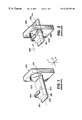
- FIG. 5 is a side view of a target position verification system in accordance with the present invention, viewed along the longitudinal axis of treatment table of the radiation therapy device;
- FIG. 6 is a flowchart illustrating the step-by-step method of the present invention.
- FIG. 7 is a front view of a computer screen displaying two two-dimensional representations of treatment plan data being aligned with two two-dimensional ultrasound images of the target, wherein the representations of treatment plan data are dose distribution contours;
- FIG. 8 is a view of a computer screen displaying two two-dimensional representations of treatment plan data being aligned with two two-dimensional ultrasound images of the target, wherein the representations of treatment plan data are structure contours.
- a conventional imaging device 300 is schematically shown and includes a conventional imaging table 301 , upon which is disposed a patient 302 having a tumor, or target, 303 within the patient's body 302 .
- a tumor or an organ, or portion thereof to be treated, or an organ, sensitive structure, or portion thereof, which is not to be treated in the radiation therapy plan.
- Imaging device 300 may be a computerized tomographic (“CT”) scanning device, as illustrated in FIG. 1, or may alternatively be a magnetic resonance (“MR”) imaging device, as are known in the art.
- CT computerized tomographic
- MR magnetic resonance
- CT scanning devices such as imaging device 300 , produce an image representing a “slice” of body tissue 304 (shown in phantom lines in FIG. 2 ), one such slice being illustrated in FIG. 3.
- a plurality of images, or diagnostic images, 304 are obtained by the imaging device 300 , and this series of “slices”, which constitute a complete CT study, represent a three-dimensional picture of a particular volume, or section, of the patient's body, such as that portion of the patient's body 302 which includes target 303 therein.
- the plurality of “slices”, or diagnostic images, 304 are obtained by moving the patient 302 , disposed upon imaging table 301 , through imaging device 300 in the direction shown by arrow 305 as illustrated in FIG. 2 .
- the orientation of the patient 302 upon imaging table 301 when the slices, or images, 304 are made may be predetermined, or known, as by fixating the patient's body 302 to the imaging table 301 by use of a conventional fixation device 306 .
- Fixation device 306 illustrated schematically in FIGS. 1 and 2, and as shown in the slice, or image 304 , of FIG. 3, may be any conventional invasive, or noninvasive, fixation device which attaches to the patient 302 a coordinate system and secures the patient to the imaging table 301 .
- the coordinate system is one which is forced by its attachment mechanism to be coplanar with the plane 307 in which lies the upper surface 308 of imaging table 301 ; however, any fixation device 306 having a coordinate system may be utilized provided the relationship between the coordinate system and the imaging table 301 is known, when it is desired to fixate patient 302 .
- the target 303 is shown disposed within the patient's body 302 at a particular location having conventional X, Y, and Z coordinates, which are determined in a conventional manner by the CT scanner with respect to the frame of reference, or the coordinate system, of the imaging device as shown by its X, Y and Z axes in FIG. 1 .
- the cross-sectional configuration of target 303 in FIG. 3 appears as circular, for illustrative purposes only.
- the series of slices, or images, 304 of the patient's body 302 which include target 303 therein, are obtained, the series of slices, or diagnostic images are then transferred in a conventional manner to a conventional radiation treatment planning system which includes conventional software to permit a physician to two-dimensionally outline the outer surface 310 of target 303 in each slice 304 .
- the computer software of the radiation treatment planning system may also construct, or create, a three-dimensional rendering of the outer surface 310 of target 303 from the plurality of slices, or diagnostic images, 304 .
- its frame of reference is the longitudinal axis 312 , or Z axis, of imaging table 301 .
- a radiation treatment plan is generated by the radiation treatment planning system, whereby target 303 may receive the necessary radiation dose to properly treat target 303 .
- the radiation treatment plan could be, if desired, a conformal radiation treatment plan, whereby the shape of the radiation beam will conform to the spacial contour, or outline, 310 of target 303 as seen by the radiation beam as it passes through the target 303 , or the “beam's eye view” of the target 303 during rotation of the radiation beam source about the target 303 .
- a conventional radiation treatment device 400 which is preferably a conventional linear accelerator 401 , includes a gantry 402 , turntable 403 which causes treatment table 404 to rotate therewith, and a collimator 405 , which preferably is a collimator capable of conforming the shape of the radiation beam to conform to the beam's eye view of the target being treated.
- the three axes of rotation of the gantry 402 , turntable and treatment table 403 , 404 and collimator 405 are designated with the letters G, T, and C, respectively.
- the target 303 within patient's body 302 is disposed in the patient's head in FIG.
- the method and apparatus of the present invention may be used with targets disposed anywhere in the patient's body, that can be seen by the imaging device 300 .
- the target 303 which is treated by linear accelerator 401 is disposed at the isocenter 406 of the linear accelerator 401 .
- the isocenter 406 is defined as the point of intersection of the three axes of rotation, C, G, and T of linear accelerator 401 .
- the previously described radiation treatment plan controls the operation of linear accelerator 401 , and controls the operation of collimator 405 , rotation of gantry 402 , and location of treatment table 404 , in a conventional manner.
- the position and orientation of target 303 within patient's body 302 with respect to linear accelerator 401 may not necessarily be the same as the position and orientation of target 303 which was utilized in developing the radiation treatment plan.
- the present invention is used to verify that the position and orientation of target 303 within the patient's body 302 conforms, or matches, the position and orientation of the target 303 in the diagnostic slices 304 utilized in developing the radiation treatment plan.
- patient 302 is disposed on treatment table 404 , with patient 302 laying flat upon treatment table 404 , although patient 302 may not be laying precisely in the same orientation with respect to treatment table 404 , as patient 302 had when patient 302 was lying upon imaging table 301 .
- Patient 302 is laying on the upper surface 438 of treatment table 404 , with the patient's spinal cord 502 being disposed substantially parallel with the longitudinal axis 435 of treatment table 404 .
- the patient's orientation on the treatment table 404 need not be precisely the same as its orientation on imaging table 301 ; however patient 302 is preferably laying flat on treatment table 404 . Since the orientation of the patient's body 302 is not the same as it was when the patient 302 was imaged by imaging device 300 , it should be apparent that it is very likely the position and orientation of target 303 with respect to treatment table 404 and linear accelerator 401 will not conform, or match, the position and orientation of target 303 upon which the radiation treatment plan for linear accelerator 401 has been based.
- the target verification system 500 of the present invention generally includes: a means for generating 510 at least two two-dimensional ultrasound images 700 , 750 , 800 , 850 (FIGS. 7 and 8) of the target 303 ; a position sensing system 520 for indicating the position of the generating means 510 with respect to the radiation therapy device 400 (FIG. 4 ), whereby the location of the target 303 with respect to the radiation therapy device is known; and a computer 490 having a monitor 495 associated therewith.
- target 303 in FIG. 5 is located in the patient's prostate.
- the means for generating 510 the ultrasound image, such as 700 is an ultrasound image generator, such as an ultrasound probe 511 and may be a commercially available ultrasound probe 511 , Model 4.5/50 from Diasonics Vingmed Ultrasound, Inc. of Santa Clara, Calif.
- Ultrasound probe 511 can generate two-dimensional ultrasound images of the portion of the patient's body 302 containing target 303 , while patient 302 is on treatment table 404 .
- Ultrasound probe 511 may be provided in any suitable manner as by attaching or mounting it to radiation therapy device 400 , treatment table 404 , gantry 402 , or any other available location, provided the position sensing system, or means, 520 , can determine the position of ultrasound probe 511 with respect to the radiation therapy device 400 .
- position sensing system 520 is a position sensor, such as a 3-D digitizer articulated arm 521 .
- the 3-D digitizer articulated arm 521 is preferably a commercially available, model Microscribe 3DX, 3-D digitizer articulated arm 521 manufactured by Immersion Corporation of San Jose, Calif.
- Other types of position sensors could be utilized to determine the position of the ultrasound probe 511 , or any other type of image generator which is utilized, as will be hereinafter discussed. Examples of such position sensors are: camera systems; retro reflectors; and laser positioning systems, among others.
- Articulated arm 321 includes a plurality of sensors (not shown) which track the position and orientation of the first end 522 of arm 521 to which probe 511 is mounted.
- the output of the sensors in conjunction with computer 490 indicate the position of ultrasound probe 511 with respect to radiation therapy device 400 .
- This position sensing system 520 tracks the position and orientation of the ultrasound probe 511 .
- Position sensing systems other than articulated arm technology such as 3-D digitizer articulated arm 521 , may be used with ultrasound probe 511 . Examples of other types of position sensing systems that may be used are those based on: triangulating directional microphones and spark gaps; video camera arrays; and magnetic field orientation.
- Base unit 530 While the first end 522 of 3-D digitizer articulated arm 521 is connected to ultrasound probe 511 , a second end 523 of articulated arm 521 is associated with the base unit 530 which contains some of the circuitry and sensors for articulated arm 521 .
- Base unit 530 also includes a tilt sensor 531 which can indicate if articulated arm is level with respect to gravity, in the event floor 545 is not exactly level, which in turn can also affect the angular disposition of the gantry 402 .
- the angular disposition of the cart 541 upon which the base unit 530 may be disposed, may be determined; and the angular disposition of the gantry 402 may also be determined, so that the articulated arm 521 may be, aligned, or oriented, to the radiation therapy device, as will be hereinafter described.
- Disposed between first and second ends 522 , 523 is a joint member 524 , which assists in articulation of the arm 521 .
- the first end 522 of articulated arm 521 may be rotated about joint member 524 and the second end 523 of arm 521 can also rotate about base unit 530 , as is conventional in the art.
- Appropriate software associated with 3-D digitizer articulated arm 521 in cooperation with computer 490 , permits the operator of the target position verification system 500 to always know the position and orientation of ultrasound probe 511 , as will be hereinafter described in greater detail.
- the articulated arm 521 is mounted on a support 540 adjacent treatment table 404 .
- support 540 is a moveable support, or cart 541 , disposed on a plurality of wheels 542 .
- the target position verification system 500 may be easily placed at its preferred location adjacent treatment table 404 . It may also be readily moved away from treatment table 404 at the time the radiation therapy treatment is to begin, and may be conveniently moved and stored out of the way of the radiation therapy device 400 .
- the base unit 530 is preferably firmly attached to the support member 540 , or cart 541 .
- the first step 610 is to set up and align, or orient, the 3-D digitizer articulated arm 521 to radiation therapy device 400 , in order to align the ultrasound probe 511 to the radiation therapy device 400 , coordinate system.
- the geometric orientation, or location, of the ultrasound image generating means 510 , or ultrasound probe 511 , mounted to articulated arm 521 will be known with respect to the radiation therapy device 400 . In turn such geometric orientation will be known for each ultrasound image to be generated.
- Step 610 can be accomplished by several techniques.
- ultrasound probe 511 mounted upon 3-D digitizer articulated arm 521 , may be releasably secured to radiation therapy device 400 , as by releasably securing ultrasound probe 511 to gantry 402 or collimator 405 (FIG. 4 ).
- a receptacle, or holster, (not shown), may be attached to gantry 402 or collimator 405 , and the ultrasound probe 511 may be releasably secured within the receptacle mounted on the gantry 402 or collimator 405 .
- the 3-D digitizer articulated arm 521 operates in a conventional manner, in combination with computer 490 and related software, to indicate where ultrasound probe 511 is geometrically disposed, or located, with respect to radiation therapy device 400 .
- the geometric orientation, or location, of ultrasound probe 511 will always be known regardless of where ultrasound probe is located, such as in the location illustrated in FIG. 5 adjacent the patient's body 302 .
- Another technique entails identifying at least three points on gantry 402 by touching 3-D digitizer articulated arm 521 to the points when gantry 402 is at a known position.
- Yet another technique for aligning 3-D digitizer articulated arm 521 to radiation therapy device 400 includes the step of registering moveable support 540 , or cart 541 , and the 3-D digitizer articulated arm 521 mounted thereon, to holes 543 , or pins 544 , on the floor 545 adjacent to treatment table 550 , which holes 543 or pins 544 cooperate with the support 540 , or with the wheels 542 of cart 541 .
- the next step 620 involves disposing, or positioning, the patient 560 in a nominal treatment position upon treatment table 404 , which preferably approximates the position and orientation the patient 302 had during the imaging process. It should be noted that the set-up step 610 could alternatively follow, rather than precede, the patient positioning step 620 .
- the next step of the method of the present invention is to generate, or acquire, at least two two-dimensional ultrasound images of the target 303 in the patient's body 302 . If only two ultrasound images of the target 303 are taken, they must not be the same image.
- the two ultrasound images may be any two different ultrasound images of the patient 302 in the room containing the radiation therapy device.
- the at least two ultrasound images are an axial image 700 , 800 and a sagittal image 750 , 850 (FIGS. 7 and 8) of target 303 .
- These images are generated, or acquired, when ultrasound probe 511 is disposed in the known geometrical orientation, as previously described, through operation of the position sensing system 520 , or articulated arm 521 .
- An axial image 700 , 800 of target 303 is an image taken in a plane approximately perpendicular to the spinal cord, or longitudinal axis, of the patient 302 , as well as perpendicular to the upper surface 438 of treatment table 404 , as is known in the art.
- a sagittal image 750 , 850 of target 303 is an image generated in a plane parallel with the longitudinal axis, or spinal cord, of patient 302 , as well as being perpendicular and parallel with longitudinal axis of treatment table 404 .
- ultrasound images instead of ultrasound images, a gamma camera (not shown) could be used as an image generator and could be used to image radioisotope labeled targets 303 in the patient 302 .
- the images could be plain x-rays or fluoroscopic images displaying patient anatomy with, or without, implanted markers. Any two different images, of many different types, of the patient 302 in the room containing the radiation therapy device could be used.
- the radiation treatment plan data is what is known as a center slice two-dimensional radiation treatment plan
- the center of the target 303 , or organ can be matched with a single two dimensional slice image
- the method and apparatus of the present invention as hereinafter described, may be also utilized to verify the position of the target 303 .
- the next step 640 of the method of the present invention is to display at least two two-dimensional representations of treatment plan data corresponding to target 303 , and then manipulate, or align, the displayed representations of treatment plan data with respect to the displayed ultrasound images, such as images 700 , 750 , or images 800 , 850 , as will be hereinafter described in greater detail.
- the radiation treatment plan can include various types of two-dimensional representations of treatment plan data, in a conventional manner, such as dose distribution contours 710 , 740 (FIG. 7 ), and structure contours 810 , 840 (FIG. 8 ), as is known in the art.
- the underlying treatment plan data may be a three-dimensional representation of data which is converted into a two-dimensional representation. Additionally, the radiation treatment plan can generate two-dimensional representations of geometric information concerning radiation beam projections and isocenter location (not shown) which may also be displayed on screen 1000 of monitor 495 .
- the two-dimensional representations of treatment plan data can also include actual CT or MR images of the patient 302 .
- treatment plan data can include any images or data that can be used to generate, evaluate, or create, a radiation treatment plan. As shown on the left side of FIG.
- an axial ultrasound image 700 of the prostate of patient 302 is displayed and an axial dose distribution contour 710 associated with the patient's prostate in the radiation treatment plan data has been displayed and overlaid, or aligned, with the ultrasound image 700 .
- a sagittal ultrasound image 750 of the patient's prostate, or target 303 has been displayed, along with the display of a sagittal dose distribution contour 740 .
- axial and sagittal ultrasound images, 800 , 850 are displayed, with axial and sagittal structure contours 810 , 840 being also displayed, and aligned with or overlaid upon the ultrasound images 800 , 850 .
- the operator, or user, of the target position verification system 500 may align, or manipulate, the representations of treatment plan data, or dose distribution contours 710 , 740 , or structure contours 810 , 840 with respect to the ultrasound images 700 , 750 , or images 800 , 850 , using the arrow keys 1010 , if the displayed treatment plan data is not initially displayed in an aligned relationship with the displayed ultrasound images.
- computer software associated with computer 490 can determine the amount of movement necessary to dispose the target 303 , or prostate, of patient 302 with respect to the radiation therapy device 400 , to conform the location of target 303 to the desired position of the target 303 in the radiation treatment plan.
- the computer software determines the necessary amount, type, and direction, of movement of treatment table 404 in order to achieve the desired location of the target 303 in the radiation treatment plan.
- an amount, type and direction of movement of the radiation therapy device 400 and/or patient 302 can also be determined.
- the arrow keys 1010 are defined for the couch, or treatment table, 404 motion directions of up, down, in, out, right, and left, and the output of that process is the set of offsets in treatment table position required to realize the desired positioning of the target 303 in the radiation treatment plan. This step allows real-time correlation, display, and alignment of target 303 with patient 302 coordinate system and two-dimensional representations of treatment plan data from the radiation treatment plan.
- the computer software can determine the necessary set of offsets in three dimensions as previously described. It should be noted that if only one ultrasound image is utilized, the computer software could determine a set of two dimensional offsets which could be useful in some medical applications, including some radiation treatment plans.
- next step 650 is to reposition, or move, the treatment table, or couch, 404 , the gantry 402 , and/or collimator 405 , according to the necessary amount, type, and direction, of movement of the treatment table 404 , gantry 402 , and/or collimator 405 , determined by computer 490 , in order to conform the desired position of target 303 in the radiation treatment plan.
- the patient's body 302 may also be repositioned to achieve proper rotational and/or tilt alignment.
- the next step 660 is to verify the alignment, or position, of the target 303 , as by repeating steps 630 , 640 , and step 650 if necessary.
- the system 500 is used again in real-time mode to verify proper alignment at the new treatment table 404 position.
- the operator repeats step 630 to see whether the dose distribution and structure contours, or two-dimensional representations of treatment plan data, align with the ultrasound images. If the images and the contours, or two-dimensional representations of treatment plan data, do not align, the step 640 and 650 may be repeated until the desired position of the target 303 has been obtained.
- the method of the present invention may also include the step of storing the treatment plan data, representations of treatment plan data, and ultrasound images, for use in future procedures, which would include patient set-up, operator verification, physician review, and/or patient records purposes.
- the method and system 500 of the present invention may also include the utilization and providing of a digital camera (not shown) to take a picture of the patient 302 while on treatment table 404 to record the patient's identity, equipment set-up, and patient orientation, which can be stored in computer 490 for future use.
- the method and system of the present invention could be used for patient contour position validation and dosimeter placement for delivery validation using anthropomorphic phantoms.
- the arm With the ultrasound probe removed from the articulated arm, the arm may be aligned to the gantry coordinate system, and can then be used to provide dose, structure, and contour information from the treatment planning system for the point at the end of the arm. Accordingly, the invention is therefore to be limited only by the scope of the appended claims.
Abstract
Description
Claims (39)
Priority Applications (1)
| Application Number | Priority Date | Filing Date | Title |
|---|---|---|---|
| US09/181,496 US6325758B1 (en) | 1997-10-27 | 1998-10-27 | Method and apparatus for target position verification |
Applications Claiming Priority (2)
| Application Number | Priority Date | Filing Date | Title |
|---|---|---|---|
| US6327697P | 1997-10-27 | 1997-10-27 | |
| US09/181,496 US6325758B1 (en) | 1997-10-27 | 1998-10-27 | Method and apparatus for target position verification |
Publications (1)
| Publication Number | Publication Date |
|---|---|
| US6325758B1 true US6325758B1 (en) | 2001-12-04 |
Family
ID=26743232
Family Applications (1)
| Application Number | Title | Priority Date | Filing Date |
|---|---|---|---|
| US09/181,496 Expired - Lifetime US6325758B1 (en) | 1997-10-27 | 1998-10-27 | Method and apparatus for target position verification |
Country Status (1)
| Country | Link |
|---|---|
| US (1) | US6325758B1 (en) |
Cited By (119)
| Publication number | Priority date | Publication date | Assignee | Title |
|---|---|---|---|---|
| US6540679B2 (en) * | 2000-12-28 | 2003-04-01 | Guided Therapy Systems, Inc. | Visual imaging system for ultrasonic probe |
| US20030112922A1 (en) * | 2001-11-05 | 2003-06-19 | Computerized Medical Systems, Inc. | Apparatus and method for registration, guidance and targeting of external beam radiation therapy |
| US20030130573A1 (en) * | 2001-07-31 | 2003-07-10 | Yan Yu | Method and device for optimization of preloaded brachytherapy needles |
| US20030177039A1 (en) * | 2002-02-13 | 2003-09-18 | Nicholas Joseph A. | Method of outsourcing IMRT services |
| WO2004000120A1 (en) * | 2002-06-24 | 2003-12-31 | Raytherapy Positioning Ab | Patient representation in medical machines |
| WO2004022162A1 (en) * | 2002-09-03 | 2004-03-18 | Moshe Ein-Gal | Method and apparatus for locating a medical target |
| US20040068169A1 (en) * | 2002-10-05 | 2004-04-08 | Stan Mansfield | Imaging device for radiation treatment applications |
| WO2004033041A1 (en) * | 2002-10-07 | 2004-04-22 | Nomos Corporation | Method and apparatus for target position verification |
| US20040120452A1 (en) * | 2002-12-18 | 2004-06-24 | Shapiro Edward G. | Multi-mode cone beam CT radiotherapy simulator and treatment machine with a flat panel imager |
| US20040146141A1 (en) * | 2003-01-27 | 2004-07-29 | Siemens Medical Solutions Usa, Inc. | Predictive organ dynamics database and code |
| US20040264640A1 (en) * | 2003-06-25 | 2004-12-30 | Myles Jeremy R. | Treatment planning, simulation, and verification system |
| US20050119570A1 (en) * | 2003-12-01 | 2005-06-02 | Stephen Lewis | Ultrasonic image and visualization aid |
| US20050251029A1 (en) * | 2004-04-21 | 2005-11-10 | Ali Khamene | Radiation therapy treatment plan |
| US20060020195A1 (en) * | 2004-07-20 | 2006-01-26 | Tony Falco | Verifying lesion characteristics using beam shapes |
| US20060074301A1 (en) * | 2002-06-05 | 2006-04-06 | Eric Meier | Integrated radiation therapy systems and methods for treating a target in a patient |
| US20060215813A1 (en) * | 2005-03-23 | 2006-09-28 | Scherch John D | System for monitoring the geometry of a radiation treatment apparatus, trackable assembly, program product, and related methods |
| US20070006941A1 (en) * | 2005-07-10 | 2007-01-11 | Silva David J | Method for purging a high purity manifold |
| US20070015987A1 (en) * | 2002-10-01 | 2007-01-18 | Benlloch Baviera Jose M | Functional navigator |
| US7173265B2 (en) | 2003-08-12 | 2007-02-06 | Loma Linda University Medical Center | Modular patient support system |
| US7199382B2 (en) | 2003-08-12 | 2007-04-03 | Loma Linda University Medical Center | Patient alignment system with external measurement and object coordination for radiation therapy system |
| US7227925B1 (en) | 2002-10-02 | 2007-06-05 | Varian Medical Systems Technologies, Inc. | Gantry mounted stereoscopic imaging system |
| US20070253529A1 (en) * | 2006-04-13 | 2007-11-01 | Seppi Edward J | Systems and methods for digital volumetric laminar tomography |
| US20070276247A1 (en) * | 2002-06-07 | 2007-11-29 | Vikram Chalana | Systems and methods for ultrasound imaging using an inertial reference unit |
| US20080219405A1 (en) * | 2005-09-06 | 2008-09-11 | Tony Falco | System and method for patient setup for radiotherapy treatment |
| US20090024030A1 (en) * | 2007-07-20 | 2009-01-22 | Martin Lachaine | Methods and systems for guiding the acquisition of ultrasound images |
| US20090129545A1 (en) * | 1999-03-16 | 2009-05-21 | Accuray, Inc. | Frameless radiosurgery treatment system and method |
| US7789560B2 (en) | 2001-10-30 | 2010-09-07 | Loma Linda University Medical Center | Method and device for delivering radiotherapy |
| EP1759733A3 (en) * | 2005-08-31 | 2010-10-20 | Hitachi, Ltd. | Positioning system and method for radiation therapy |
| US7819806B2 (en) | 2002-06-07 | 2010-10-26 | Verathon Inc. | System and method to identify and measure organ wall boundaries |
| US7899513B2 (en) | 2004-07-23 | 2011-03-01 | Calypso Medical Technologies, Inc. | Modular software system for guided radiation therapy |
| US7984715B2 (en) | 2004-06-25 | 2011-07-26 | Loma Linda University Medical Center | Method and device for registration and immobilization |
| US20110306025A1 (en) * | 2010-05-13 | 2011-12-15 | Higher Education | Ultrasound Training and Testing System with Multi-Modality Transducer Tracking |
| US8088072B2 (en) * | 2007-10-12 | 2012-01-03 | Gynesonics, Inc. | Methods and systems for controlled deployment of needles in tissue |
| US8133181B2 (en) | 2007-05-16 | 2012-03-13 | Verathon Inc. | Device, system and method to measure abdominal aortic aneurysm diameter |
| US8135198B2 (en) | 2007-08-08 | 2012-03-13 | Resonant Medical, Inc. | Systems and methods for constructing images |
| US8167803B2 (en) | 2007-05-16 | 2012-05-01 | Verathon Inc. | System and method for bladder detection using harmonic imaging |
| US8189889B2 (en) | 2008-02-22 | 2012-05-29 | Loma Linda University Medical Center | Systems and methods for characterizing spatial distortion in 3D imaging systems |
| US8189738B2 (en) | 2008-06-02 | 2012-05-29 | Elekta Ltd. | Methods and systems for guiding clinical radiotherapy setups |
| US8210899B2 (en) | 2006-11-21 | 2012-07-03 | Loma Linda University Medical Center | Device and method for immobilizing patients for breast radiation therapy |
| US8221322B2 (en) | 2002-06-07 | 2012-07-17 | Verathon Inc. | Systems and methods to improve clarity in ultrasound images |
| US8221321B2 (en) | 2002-06-07 | 2012-07-17 | Verathon Inc. | Systems and methods for quantification and classification of fluids in human cavities in ultrasound images |
| US8239005B2 (en) | 2004-07-23 | 2012-08-07 | Varian Medical Systems, Inc. | Systems and methods for real-time tracking of targets in radiation therapy and other medical applications |
| US8249317B2 (en) | 2007-07-20 | 2012-08-21 | Eleckta Ltd. | Methods and systems for compensating for changes in anatomy of radiotherapy patients |
| US8308644B2 (en) | 2002-08-09 | 2012-11-13 | Verathon Inc. | Instantaneous ultrasonic measurement of bladder volume |
| US8437449B2 (en) | 2004-07-23 | 2013-05-07 | Varian Medical Systems, Inc. | Dynamic/adaptive treatment planning for radiation therapy |
| US20130289400A1 (en) * | 2010-01-29 | 2013-10-31 | Weill Cornell Medical College | Devices, apparatus and methods for analyzing, affecting and/or treating one or more anatomical structures |
| US8636665B2 (en) | 2004-10-06 | 2014-01-28 | Guided Therapy Systems, Llc | Method and system for ultrasound treatment of fat |
| US8641622B2 (en) | 2004-10-06 | 2014-02-04 | Guided Therapy Systems, Llc | Method and system for treating photoaged tissue |
| US8663112B2 (en) | 2004-10-06 | 2014-03-04 | Guided Therapy Systems, Llc | Methods and systems for fat reduction and/or cellulite treatment |
| US8690778B2 (en) | 2004-10-06 | 2014-04-08 | Guided Therapy Systems, Llc | Energy-based tissue tightening |
| US20140114173A1 (en) * | 2012-10-19 | 2014-04-24 | Biosense Webster (Israel), Ltd. | Integration between 3d maps and fluoroscopic images |
| US8858471B2 (en) | 2011-07-10 | 2014-10-14 | Guided Therapy Systems, Llc | Methods and systems for ultrasound treatment |
| US8857438B2 (en) | 2010-11-08 | 2014-10-14 | Ulthera, Inc. | Devices and methods for acoustic shielding |
| US8868958B2 (en) | 2005-04-25 | 2014-10-21 | Ardent Sound, Inc | Method and system for enhancing computer peripheral safety |
| US8915853B2 (en) | 2004-10-06 | 2014-12-23 | Guided Therapy Systems, Llc | Methods for face and neck lifts |
| US8915870B2 (en) | 2004-10-06 | 2014-12-23 | Guided Therapy Systems, Llc | Method and system for treating stretch marks |
| US8932224B2 (en) | 2004-10-06 | 2015-01-13 | Guided Therapy Systems, Llc | Energy based hyperhidrosis treatment |
| US9011337B2 (en) | 2011-07-11 | 2015-04-21 | Guided Therapy Systems, Llc | Systems and methods for monitoring and controlling ultrasound power output and stability |
| US9011336B2 (en) | 2004-09-16 | 2015-04-21 | Guided Therapy Systems, Llc | Method and system for combined energy therapy profile |
| US9039617B2 (en) | 2009-11-24 | 2015-05-26 | Guided Therapy Systems, Llc | Methods and systems for generating thermal bubbles for improved ultrasound imaging and therapy |
| US9072895B2 (en) | 2001-06-08 | 2015-07-07 | Varian Medical Systems, Inc. | Guided radiation therapy system |
| US9108048B2 (en) | 2010-08-06 | 2015-08-18 | Accuray Incorporated | Systems and methods for real-time tumor tracking during radiation treatment using ultrasound imaging |
| US9114247B2 (en) | 2004-09-16 | 2015-08-25 | Guided Therapy Systems, Llc | Method and system for ultrasound treatment with a multi-directional transducer |
| US9149658B2 (en) | 2010-08-02 | 2015-10-06 | Guided Therapy Systems, Llc | Systems and methods for ultrasound treatment |
| US9213107B2 (en) | 2009-10-01 | 2015-12-15 | Loma Linda University Medical Center | Ion induced impact ionization detector and uses thereof |
| US9216276B2 (en) | 2007-05-07 | 2015-12-22 | Guided Therapy Systems, Llc | Methods and systems for modulating medicants using acoustic energy |
| US9237860B2 (en) | 2008-06-05 | 2016-01-19 | Varian Medical Systems, Inc. | Motion compensation for medical imaging and associated systems and methods |
| US9248316B2 (en) | 2010-01-12 | 2016-02-02 | Elekta Ltd. | Feature tracking using ultrasound |
| US9263663B2 (en) | 2012-04-13 | 2016-02-16 | Ardent Sound, Inc. | Method of making thick film transducer arrays |
| US20160045768A1 (en) * | 2006-05-25 | 2016-02-18 | William Beaumont Hospital | Real-time, on-line and offline treatment dose tracking and feedback process for volumetric image guided adaptive radiotherapy |
| US9272162B2 (en) | 1997-10-14 | 2016-03-01 | Guided Therapy Systems, Llc | Imaging, therapy, and temperature monitoring ultrasonic method |
| US9320917B2 (en) | 2010-01-05 | 2016-04-26 | William Beaumont Hospital | Intensity modulated arc therapy with continuous coach rotation/shift and simultaneous cone beam imaging |
| US9320537B2 (en) | 2004-10-06 | 2016-04-26 | Guided Therapy Systems, Llc | Methods for noninvasive skin tightening |
| US9339243B2 (en) | 2006-04-14 | 2016-05-17 | William Beaumont Hospital | Image guided radiotherapy with dual source and dual detector arrays tetrahedron beam computed tomography |
| US9451928B2 (en) | 2006-09-13 | 2016-09-27 | Elekta Ltd. | Incorporating internal anatomy in clinical radiotherapy setups |
| US9498167B2 (en) | 2005-04-29 | 2016-11-22 | Varian Medical Systems, Inc. | System and methods for treating patients using radiation |
| US9504446B2 (en) | 2010-08-02 | 2016-11-29 | Guided Therapy Systems, Llc | Systems and methods for coupling an ultrasound source to tissue |
| US9510802B2 (en) | 2012-09-21 | 2016-12-06 | Guided Therapy Systems, Llc | Reflective ultrasound technology for dermatological treatments |
| US9566454B2 (en) | 2006-09-18 | 2017-02-14 | Guided Therapy Systems, Llc | Method and sysem for non-ablative acne treatment and prevention |
| US9586059B2 (en) | 2004-07-23 | 2017-03-07 | Varian Medical Systems, Inc. | User interface for guided radiation therapy |
| US9630025B2 (en) | 2005-07-25 | 2017-04-25 | Varian Medical Systems International Ag | Methods and apparatus for the planning and delivery of radiation treatments |
| US9694212B2 (en) | 2004-10-06 | 2017-07-04 | Guided Therapy Systems, Llc | Method and system for ultrasound treatment of skin |
| US9700340B2 (en) | 2004-10-06 | 2017-07-11 | Guided Therapy Systems, Llc | System and method for ultra-high frequency ultrasound treatment |
| US9827449B2 (en) | 2004-10-06 | 2017-11-28 | Guided Therapy Systems, L.L.C. | Systems for treating skin laxity |
| US9907535B2 (en) | 2000-12-28 | 2018-03-06 | Ardent Sound, Inc. | Visual imaging system for ultrasonic probe |
| US9919165B2 (en) | 2014-05-07 | 2018-03-20 | Varian Medical Systems, Inc. | Systems and methods for fiducial to plan association |
| US9943704B1 (en) | 2009-01-21 | 2018-04-17 | Varian Medical Systems, Inc. | Method and system for fiducials contained in removable device for radiation therapy |
| US9950194B2 (en) | 2014-09-09 | 2018-04-24 | Mevion Medical Systems, Inc. | Patient positioning system |
| US10004650B2 (en) | 2005-04-29 | 2018-06-26 | Varian Medical Systems, Inc. | Dynamic patient positioning system |
| USRE46953E1 (en) | 2007-04-20 | 2018-07-17 | University Of Maryland, Baltimore | Single-arc dose painting for precision radiation therapy |
| US10043284B2 (en) | 2014-05-07 | 2018-08-07 | Varian Medical Systems, Inc. | Systems and methods for real-time tumor tracking |
| US10039938B2 (en) | 2004-09-16 | 2018-08-07 | Guided Therapy Systems, Llc | System and method for variable depth ultrasound treatment |
| US10182868B2 (en) | 2005-11-17 | 2019-01-22 | Varian Medical Systems, Inc. | Apparatus and methods for using an electromagnetic transponder in orthopedic procedures |
| US10195464B2 (en) | 2004-06-24 | 2019-02-05 | Varian Medical Systems, Inc. | Systems and methods for treating a lung of a patient using guided radiation therapy or surgery |
| EP3446633A1 (en) * | 2009-07-10 | 2019-02-27 | Elekta Ltd. | Adaptive radiotherapy treatment using ultrasound |
| US10293135B2 (en) | 2010-10-01 | 2019-05-21 | Varian Medical Systems, Inc. | Delivery catheter for and method of delivering implant, for example, bronchoscopically implanting a marker in a lung |
| US10420960B2 (en) | 2013-03-08 | 2019-09-24 | Ulthera, Inc. | Devices and methods for multi-focus ultrasound therapy |
| US10449390B2 (en) | 2010-01-12 | 2019-10-22 | Elekta ltd | Feature tracking using ultrasound |
| US10537304B2 (en) | 2008-06-06 | 2020-01-21 | Ulthera, Inc. | Hand wand for ultrasonic cosmetic treatment and imaging |
| US10561862B2 (en) | 2013-03-15 | 2020-02-18 | Guided Therapy Systems, Llc | Ultrasound treatment device and methods of use |
| US10603521B2 (en) | 2014-04-18 | 2020-03-31 | Ulthera, Inc. | Band transducer ultrasound therapy |
| US10603127B2 (en) * | 2005-06-06 | 2020-03-31 | Intuitive Surgical Operations, Inc. | Laparoscopic ultrasound robotic surgical system |
| US10653496B2 (en) | 2005-09-19 | 2020-05-19 | Varian Medical Systems, Inc. | Apparatus and methods for implanting objects, such as a bronchoscopically implanting markers in the lung of patients |
| US10773101B2 (en) | 2010-06-22 | 2020-09-15 | Varian Medical Systems International Ag | System and method for estimating and manipulating estimated radiation dose |
| US10806409B2 (en) | 2016-09-23 | 2020-10-20 | Varian Medical Systems International Ag | Medical systems with patient supports |
| US10864385B2 (en) | 2004-09-24 | 2020-12-15 | Guided Therapy Systems, Llc | Rejuvenating skin by heating tissue for cosmetic treatment of the face and body |
| US10993770B2 (en) | 2016-11-11 | 2021-05-04 | Gynesonics, Inc. | Controlled treatment of tissue and dynamic interaction with, and comparison of, tissue and/or treatment data |
| US11135447B2 (en) * | 2015-07-17 | 2021-10-05 | Koninklijke Philips N.V. | Guidance for lung cancer radiation |
| US11207548B2 (en) | 2004-10-07 | 2021-12-28 | Guided Therapy Systems, L.L.C. | Ultrasound probe for treating skin laxity |
| US11224895B2 (en) | 2016-01-18 | 2022-01-18 | Ulthera, Inc. | Compact ultrasound device having annular ultrasound array peripherally electrically connected to flexible printed circuit board and method of assembly thereof |
| US11235179B2 (en) | 2004-10-06 | 2022-02-01 | Guided Therapy Systems, Llc | Energy based skin gland treatment |
| US11241218B2 (en) | 2016-08-16 | 2022-02-08 | Ulthera, Inc. | Systems and methods for cosmetic ultrasound treatment of skin |
| US11259870B2 (en) | 2005-06-06 | 2022-03-01 | Intuitive Surgical Operations, Inc. | Interactive user interfaces for minimally invasive telesurgical systems |
| US11478662B2 (en) | 2017-04-05 | 2022-10-25 | Accuray Incorporated | Sequential monoscopic tracking |
| US11717661B2 (en) | 2007-05-07 | 2023-08-08 | Guided Therapy Systems, Llc | Methods and systems for ultrasound assisted delivery of a medicant to tissue |
| US11724133B2 (en) | 2004-10-07 | 2023-08-15 | Guided Therapy Systems, Llc | Ultrasound probe for treatment of skin |
| US20230330437A1 (en) * | 2022-04-14 | 2023-10-19 | Varian Medical Systems, Inc. | Phantom holder for radiation therapy system |
| US11883688B2 (en) | 2004-10-06 | 2024-01-30 | Guided Therapy Systems, Llc | Energy based fat reduction |
| US11944849B2 (en) | 2018-02-20 | 2024-04-02 | Ulthera, Inc. | Systems and methods for combined cosmetic treatment of cellulite with ultrasound |
Citations (6)
| Publication number | Priority date | Publication date | Assignee | Title |
|---|---|---|---|---|
| US5391139A (en) * | 1992-09-03 | 1995-02-21 | William Beaumont Hospital | Real time radiation treatment planning system |
| US5394875A (en) * | 1993-10-21 | 1995-03-07 | Lewis; Judith T. | Automatic ultrasonic localization of targets implanted in a portion of the anatomy |
| US5411026A (en) * | 1993-10-08 | 1995-05-02 | Nomos Corporation | Method and apparatus for lesion position verification |
| US5447154A (en) * | 1992-07-31 | 1995-09-05 | Universite Joseph Fourier | Method for determining the position of an organ |
| US5690107A (en) * | 1995-07-08 | 1997-11-25 | Lap Gmbh Laser Applikationen | Method for positioning and marking a patient at a diagnostic apparatus |
| US5810007A (en) * | 1995-07-26 | 1998-09-22 | Associates Of The Joint Center For Radiation Therapy, Inc. | Ultrasound localization and image fusion for the treatment of prostate cancer |
-
1998
- 1998-10-27 US US09/181,496 patent/US6325758B1/en not_active Expired - Lifetime
Patent Citations (6)
| Publication number | Priority date | Publication date | Assignee | Title |
|---|---|---|---|---|
| US5447154A (en) * | 1992-07-31 | 1995-09-05 | Universite Joseph Fourier | Method for determining the position of an organ |
| US5391139A (en) * | 1992-09-03 | 1995-02-21 | William Beaumont Hospital | Real time radiation treatment planning system |
| US5411026A (en) * | 1993-10-08 | 1995-05-02 | Nomos Corporation | Method and apparatus for lesion position verification |
| US5394875A (en) * | 1993-10-21 | 1995-03-07 | Lewis; Judith T. | Automatic ultrasonic localization of targets implanted in a portion of the anatomy |
| US5690107A (en) * | 1995-07-08 | 1997-11-25 | Lap Gmbh Laser Applikationen | Method for positioning and marking a patient at a diagnostic apparatus |
| US5810007A (en) * | 1995-07-26 | 1998-09-22 | Associates Of The Joint Center For Radiation Therapy, Inc. | Ultrasound localization and image fusion for the treatment of prostate cancer |
Cited By (261)
| Publication number | Priority date | Publication date | Assignee | Title |
|---|---|---|---|---|
| US9272162B2 (en) | 1997-10-14 | 2016-03-01 | Guided Therapy Systems, Llc | Imaging, therapy, and temperature monitoring ultrasonic method |
| US8634898B2 (en) | 1999-03-16 | 2014-01-21 | Accuray Incorporated | Frameless radiosurgery treatment system and method |
| US20090129545A1 (en) * | 1999-03-16 | 2009-05-21 | Accuray, Inc. | Frameless radiosurgery treatment system and method |
| US8086299B2 (en) * | 1999-03-16 | 2011-12-27 | Accuray Incorporated | Frameless radiosurgery treatment system and method |
| US20030176790A1 (en) * | 2000-12-28 | 2003-09-18 | Guided Therapy Systems, Inc. | Visual imaging system for ultrasonic probe |
| US6540679B2 (en) * | 2000-12-28 | 2003-04-01 | Guided Therapy Systems, Inc. | Visual imaging system for ultrasonic probe |
| US9907535B2 (en) | 2000-12-28 | 2018-03-06 | Ardent Sound, Inc. | Visual imaging system for ultrasonic probe |
| US7142905B2 (en) | 2000-12-28 | 2006-11-28 | Guided Therapy Systems, Inc. | Visual imaging system for ultrasonic probe |
| US9072895B2 (en) | 2001-06-08 | 2015-07-07 | Varian Medical Systems, Inc. | Guided radiation therapy system |
| US20030130573A1 (en) * | 2001-07-31 | 2003-07-10 | Yan Yu | Method and device for optimization of preloaded brachytherapy needles |
| US7789560B2 (en) | 2001-10-30 | 2010-09-07 | Loma Linda University Medical Center | Method and device for delivering radiotherapy |
| US8376613B2 (en) | 2001-10-30 | 2013-02-19 | Loma Linda University Medical Center | Method and device for delivering radiotherapy |
| US8083408B2 (en) | 2001-10-30 | 2011-12-27 | Loma Linda University Medical Center | Method and device for delivering radiotherapy |
| US20030112922A1 (en) * | 2001-11-05 | 2003-06-19 | Computerized Medical Systems, Inc. | Apparatus and method for registration, guidance and targeting of external beam radiation therapy |
| US7438685B2 (en) * | 2001-11-05 | 2008-10-21 | Computerized Medical Systems, Inc. | Apparatus and method for registration, guidance and targeting of external beam radiation therapy |
| US20030177039A1 (en) * | 2002-02-13 | 2003-09-18 | Nicholas Joseph A. | Method of outsourcing IMRT services |
| US9616248B2 (en) | 2002-06-05 | 2017-04-11 | Varian Medical Systems, Inc. | Integrated radiation therapy systems and methods for treating a target in a patient |
| US9682253B2 (en) | 2002-06-05 | 2017-06-20 | Varian Medical Systems, Inc. | Integrated radiation therapy systems and methods for treating a target in a patient |
| US20060074301A1 (en) * | 2002-06-05 | 2006-04-06 | Eric Meier | Integrated radiation therapy systems and methods for treating a target in a patient |
| US7819806B2 (en) | 2002-06-07 | 2010-10-26 | Verathon Inc. | System and method to identify and measure organ wall boundaries |
| US8221322B2 (en) | 2002-06-07 | 2012-07-17 | Verathon Inc. | Systems and methods to improve clarity in ultrasound images |
| US8221321B2 (en) | 2002-06-07 | 2012-07-17 | Verathon Inc. | Systems and methods for quantification and classification of fluids in human cavities in ultrasound images |
| US20070276247A1 (en) * | 2002-06-07 | 2007-11-29 | Vikram Chalana | Systems and methods for ultrasound imaging using an inertial reference unit |
| EP2239010A1 (en) | 2002-06-24 | 2010-10-13 | C-rad Positioning Ab | Patient representation in medical machines |
| US20040002641A1 (en) * | 2002-06-24 | 2004-01-01 | Bo Sjogren | Patient representation in medical machines |
| WO2004000120A1 (en) * | 2002-06-24 | 2003-12-31 | Raytherapy Positioning Ab | Patient representation in medical machines |
| US9993225B2 (en) | 2002-08-09 | 2018-06-12 | Verathon Inc. | Instantaneous ultrasonic echo measurement of bladder volume with a limited number of ultrasound beams |
| US8308644B2 (en) | 2002-08-09 | 2012-11-13 | Verathon Inc. | Instantaneous ultrasonic measurement of bladder volume |
| WO2004022162A1 (en) * | 2002-09-03 | 2004-03-18 | Moshe Ein-Gal | Method and apparatus for locating a medical target |
| US20070015987A1 (en) * | 2002-10-01 | 2007-01-18 | Benlloch Baviera Jose M | Functional navigator |
| US7227925B1 (en) | 2002-10-02 | 2007-06-05 | Varian Medical Systems Technologies, Inc. | Gantry mounted stereoscopic imaging system |
| US20040068169A1 (en) * | 2002-10-05 | 2004-04-08 | Stan Mansfield | Imaging device for radiation treatment applications |
| US7657304B2 (en) | 2002-10-05 | 2010-02-02 | Varian Medical Systems, Inc. | Imaging device for radiation treatment applications |
| WO2004033026A2 (en) * | 2002-10-05 | 2004-04-22 | Varian Medical Systems Technologies, Inc. | An imaging device for radiation treatment applications |
| WO2004033026A3 (en) * | 2002-10-05 | 2004-08-12 | Varian Med Sys Tech Inc | An imaging device for radiation treatment applications |
| US6961405B2 (en) | 2002-10-07 | 2005-11-01 | Nomos Corporation | Method and apparatus for target position verification |
| WO2004033041A1 (en) * | 2002-10-07 | 2004-04-22 | Nomos Corporation | Method and apparatus for target position verification |
| AU2003282690B2 (en) * | 2002-10-07 | 2008-12-18 | Best Medical International, Inc. | Method and apparatus for target position verification |
| US20050020917A1 (en) * | 2002-10-07 | 2005-01-27 | Scherch John David | Method and apparatus for target position verification |
| US8867703B2 (en) | 2002-12-18 | 2014-10-21 | Varian Medical Systems, Inc. | Multi-mode cone beam CT radiotherapy simulator and treatment machine with a flat panel imager |
| US9901750B2 (en) | 2002-12-18 | 2018-02-27 | Varian Medical Systems, Inc. | Multi-mode cone beam CT radiotherapy simulator and treatment machine with a flat panel imager |
| US9421399B2 (en) | 2002-12-18 | 2016-08-23 | Varian Medical Systems, Inc. | Multi-mode cone beam CT radiotherapy simulator and treatment machine with a flat panel imager |
| US11344748B2 (en) | 2002-12-18 | 2022-05-31 | Varian Medical Systems, Inc. | Multi-mode cone beam CT radiotherapy simulator and treatment machine with a flat panel imager |
| US20040120452A1 (en) * | 2002-12-18 | 2004-06-24 | Shapiro Edward G. | Multi-mode cone beam CT radiotherapy simulator and treatment machine with a flat panel imager |
| US7945021B2 (en) | 2002-12-18 | 2011-05-17 | Varian Medical Systems, Inc. | Multi-mode cone beam CT radiotherapy simulator and treatment machine with a flat panel imager |
| US8116430B1 (en) | 2002-12-18 | 2012-02-14 | Varian Medical Systems, Inc. | Multi-mode cone beam CT radiotherapy simulator and treatment machine with a flat panel imager |
| US20040146141A1 (en) * | 2003-01-27 | 2004-07-29 | Siemens Medical Solutions Usa, Inc. | Predictive organ dynamics database and code |
| US7206377B2 (en) * | 2003-01-27 | 2007-04-17 | Siemens Medical Solutions Usa, Inc. | Predictive organ dynamics database and code |
| US20080240353A1 (en) * | 2003-06-25 | 2008-10-02 | Myles Jeremy R | Treatment planning simulation and verification system |
| US7412029B2 (en) | 2003-06-25 | 2008-08-12 | Varian Medical Systems Technologies, Inc. | Treatment planning, simulation, and verification system |
| US8385502B1 (en) | 2003-06-25 | 2013-02-26 | Varian Medical Systems, Inc. | Treatment planning simulation and verification system |
| US8681938B2 (en) | 2003-06-25 | 2014-03-25 | Varian Medical Systems, Inc. | Treatment planning simulation and verification system |
| US7831017B2 (en) | 2003-06-25 | 2010-11-09 | Varian Medical Systems Technologies, Inc. | Treatment planning simulation and verification system |
| US20040264640A1 (en) * | 2003-06-25 | 2004-12-30 | Myles Jeremy R. | Treatment planning, simulation, and verification system |
| US7696499B2 (en) | 2003-08-12 | 2010-04-13 | Loma Linda University Medical Center | Modular patient support system |
| US7173265B2 (en) | 2003-08-12 | 2007-02-06 | Loma Linda University Medical Center | Modular patient support system |
| US8981324B2 (en) | 2003-08-12 | 2015-03-17 | Loma Linda University Medical Center | Patient alignment system with external measurement and object coordination for radiation therapy system |
| US8569720B2 (en) | 2003-08-12 | 2013-10-29 | Loma Linda University Medical Center | Patient alignment system with external measurement and object coordination for radiation therapy system |
| US8418288B2 (en) | 2003-08-12 | 2013-04-16 | Loma Linda University Medical Center | Modular patient support system |
| US7746978B2 (en) | 2003-08-12 | 2010-06-29 | Loma Linda University Medical Center | Path planning and collision avoidance for movement of instruments in a radiation therapy environment |
| US7949096B2 (en) | 2003-08-12 | 2011-05-24 | Loma Linda University Medical Center | Path planning and collision avoidance for movement of instruments in a radiation therapy environment |
| US8093569B2 (en) | 2003-08-12 | 2012-01-10 | Loma Linda University Medical Centre | Modular patient support system |
| US7199382B2 (en) | 2003-08-12 | 2007-04-03 | Loma Linda University Medical Center | Patient alignment system with external measurement and object coordination for radiation therapy system |
| US7280633B2 (en) | 2003-08-12 | 2007-10-09 | Loma Linda University Medical Center | Path planning and collision avoidance for movement of instruments in a radiation therapy environment |
| US8269195B2 (en) | 2003-08-12 | 2012-09-18 | Loma Linda University Medical Center | Patient alignment system with external measurement and object coordination for radiation therapy system |
| US7446328B2 (en) | 2003-08-12 | 2008-11-04 | Loma Linda University Medical Centre | Patient alignment system with external measurement and object coordination for radiation therapy system |
| US8184773B2 (en) | 2003-08-12 | 2012-05-22 | Loma Linda University Medical Center | Path planning and collision avoidance for movement of instruments in a radiation therapy environment |
| US20050119570A1 (en) * | 2003-12-01 | 2005-06-02 | Stephen Lewis | Ultrasonic image and visualization aid |
| US20080146933A1 (en) * | 2003-12-01 | 2008-06-19 | Stephen Lewis | Ultrasonic image and visualization aid |
| US20050251029A1 (en) * | 2004-04-21 | 2005-11-10 | Ali Khamene | Radiation therapy treatment plan |
| US11439847B2 (en) | 2004-06-24 | 2022-09-13 | Varian Medical Systems, Inc. | Systems and methods for treating a lung of a patient using guided radiation therapy or surgery |
| US10195464B2 (en) | 2004-06-24 | 2019-02-05 | Varian Medical Systems, Inc. | Systems and methods for treating a lung of a patient using guided radiation therapy or surgery |
| US7984715B2 (en) | 2004-06-25 | 2011-07-26 | Loma Linda University Medical Center | Method and device for registration and immobilization |
| US8479743B2 (en) | 2004-06-25 | 2013-07-09 | Loma Linda University Medical Center | Method and device for registration and immobilization |
| US7729744B2 (en) * | 2004-07-20 | 2010-06-01 | Resonant Medical, Inc. | Verifying lesion characteristics using beam shapes |
| US20060020195A1 (en) * | 2004-07-20 | 2006-01-26 | Tony Falco | Verifying lesion characteristics using beam shapes |
| US8239005B2 (en) | 2004-07-23 | 2012-08-07 | Varian Medical Systems, Inc. | Systems and methods for real-time tracking of targets in radiation therapy and other medical applications |
| US7899513B2 (en) | 2004-07-23 | 2011-03-01 | Calypso Medical Technologies, Inc. | Modular software system for guided radiation therapy |
| US9586059B2 (en) | 2004-07-23 | 2017-03-07 | Varian Medical Systems, Inc. | User interface for guided radiation therapy |
| US8437449B2 (en) | 2004-07-23 | 2013-05-07 | Varian Medical Systems, Inc. | Dynamic/adaptive treatment planning for radiation therapy |
| US9238151B2 (en) | 2004-07-23 | 2016-01-19 | Varian Medical Systems, Inc. | Dynamic/adaptive treatment planning for radiation therapy |
| US8340742B2 (en) * | 2004-07-23 | 2012-12-25 | Varian Medical Systems, Inc. | Integrated radiation therapy systems and methods for treating a target in a patient |
| US10039938B2 (en) | 2004-09-16 | 2018-08-07 | Guided Therapy Systems, Llc | System and method for variable depth ultrasound treatment |
| US9114247B2 (en) | 2004-09-16 | 2015-08-25 | Guided Therapy Systems, Llc | Method and system for ultrasound treatment with a multi-directional transducer |
| US9011336B2 (en) | 2004-09-16 | 2015-04-21 | Guided Therapy Systems, Llc | Method and system for combined energy therapy profile |
| US9095697B2 (en) | 2004-09-24 | 2015-08-04 | Guided Therapy Systems, Llc | Methods for preheating tissue for cosmetic treatment of the face and body |
| US11590370B2 (en) | 2004-09-24 | 2023-02-28 | Guided Therapy Systems, Llc | Rejuvenating skin by heating tissue for cosmetic treatment of the face and body |
| US9895560B2 (en) | 2004-09-24 | 2018-02-20 | Guided Therapy Systems, Llc | Methods for rejuvenating skin by heating tissue for cosmetic treatment of the face and body |
| US10328289B2 (en) | 2004-09-24 | 2019-06-25 | Guided Therapy Systems, Llc | Rejuvenating skin by heating tissue for cosmetic treatment of the face and body |
| US10864385B2 (en) | 2004-09-24 | 2020-12-15 | Guided Therapy Systems, Llc | Rejuvenating skin by heating tissue for cosmetic treatment of the face and body |
| US8672848B2 (en) | 2004-10-06 | 2014-03-18 | Guided Therapy Systems, Llc | Method and system for treating cellulite |
| US9440096B2 (en) | 2004-10-06 | 2016-09-13 | Guided Therapy Systems, Llc | Method and system for treating stretch marks |
| US8641622B2 (en) | 2004-10-06 | 2014-02-04 | Guided Therapy Systems, Llc | Method and system for treating photoaged tissue |
| US8690780B2 (en) | 2004-10-06 | 2014-04-08 | Guided Therapy Systems, Llc | Noninvasive tissue tightening for cosmetic effects |
| US8690778B2 (en) | 2004-10-06 | 2014-04-08 | Guided Therapy Systems, Llc | Energy-based tissue tightening |
| US8690779B2 (en) | 2004-10-06 | 2014-04-08 | Guided Therapy Systems, Llc | Noninvasive aesthetic treatment for tightening tissue |
| US11235179B2 (en) | 2004-10-06 | 2022-02-01 | Guided Therapy Systems, Llc | Energy based skin gland treatment |
| US10046181B2 (en) | 2004-10-06 | 2018-08-14 | Guided Therapy Systems, Llc | Energy based hyperhidrosis treatment |
| US11207547B2 (en) | 2004-10-06 | 2021-12-28 | Guided Therapy Systems, Llc | Probe for ultrasound tissue treatment |
| US11179580B2 (en) | 2004-10-06 | 2021-11-23 | Guided Therapy Systems, Llc | Energy based fat reduction |
| US8636665B2 (en) | 2004-10-06 | 2014-01-28 | Guided Therapy Systems, Llc | Method and system for ultrasound treatment of fat |
| US10046182B2 (en) | 2004-10-06 | 2018-08-14 | Guided Therapy Systems, Llc | Methods for face and neck lifts |
| US8915853B2 (en) | 2004-10-06 | 2014-12-23 | Guided Therapy Systems, Llc | Methods for face and neck lifts |
| US8915870B2 (en) | 2004-10-06 | 2014-12-23 | Guided Therapy Systems, Llc | Method and system for treating stretch marks |
| US8915854B2 (en) | 2004-10-06 | 2014-12-23 | Guided Therapy Systems, Llc | Method for fat and cellulite reduction |
| US8920324B2 (en) | 2004-10-06 | 2014-12-30 | Guided Therapy Systems, Llc | Energy based fat reduction |
| US8932224B2 (en) | 2004-10-06 | 2015-01-13 | Guided Therapy Systems, Llc | Energy based hyperhidrosis treatment |
| US11235180B2 (en) | 2004-10-06 | 2022-02-01 | Guided Therapy Systems, Llc | System and method for noninvasive skin tightening |
| US11167155B2 (en) | 2004-10-06 | 2021-11-09 | Guided Therapy Systems, Llc | Ultrasound probe for treatment of skin |
| US10010724B2 (en) | 2004-10-06 | 2018-07-03 | Guided Therapy Systems, L.L.C. | Ultrasound probe for treating skin laxity |
| US10960236B2 (en) | 2004-10-06 | 2021-03-30 | Guided Therapy Systems, Llc | System and method for noninvasive skin tightening |
| US9039619B2 (en) | 2004-10-06 | 2015-05-26 | Guided Therapy Systems, L.L.C. | Methods for treating skin laxity |
| US10010726B2 (en) | 2004-10-06 | 2018-07-03 | Guided Therapy Systems, Llc | Ultrasound probe for treatment of skin |
| US10888716B2 (en) | 2004-10-06 | 2021-01-12 | Guided Therapy Systems, Llc | Energy based fat reduction |
| US11338156B2 (en) | 2004-10-06 | 2022-05-24 | Guided Therapy Systems, Llc | Noninvasive tissue tightening system |
| US10888718B2 (en) | 2004-10-06 | 2021-01-12 | Guided Therapy Systems, L.L.C. | Ultrasound probe for treating skin laxity |
| US10010721B2 (en) | 2004-10-06 | 2018-07-03 | Guided Therapy Systems, L.L.C. | Energy based fat reduction |
| US10888717B2 (en) | 2004-10-06 | 2021-01-12 | Guided Therapy Systems, Llc | Probe for ultrasound tissue treatment |
| US10010725B2 (en) | 2004-10-06 | 2018-07-03 | Guided Therapy Systems, Llc | Ultrasound probe for fat and cellulite reduction |
| US11400319B2 (en) | 2004-10-06 | 2022-08-02 | Guided Therapy Systems, Llc | Methods for lifting skin tissue |
| US9974982B2 (en) | 2004-10-06 | 2018-05-22 | Guided Therapy Systems, Llc | System and method for noninvasive skin tightening |
| US10238894B2 (en) | 2004-10-06 | 2019-03-26 | Guided Therapy Systems, L.L.C. | Energy based fat reduction |
| US10610706B2 (en) | 2004-10-06 | 2020-04-07 | Guided Therapy Systems, Llc | Ultrasound probe for treatment of skin |
| US10610705B2 (en) | 2004-10-06 | 2020-04-07 | Guided Therapy Systems, L.L.C. | Ultrasound probe for treating skin laxity |
| US11883688B2 (en) | 2004-10-06 | 2024-01-30 | Guided Therapy Systems, Llc | Energy based fat reduction |
| US10603523B2 (en) | 2004-10-06 | 2020-03-31 | Guided Therapy Systems, Llc | Ultrasound probe for tissue treatment |
| US11697033B2 (en) | 2004-10-06 | 2023-07-11 | Guided Therapy Systems, Llc | Methods for lifting skin tissue |
| US9283410B2 (en) | 2004-10-06 | 2016-03-15 | Guided Therapy Systems, L.L.C. | System and method for fat and cellulite reduction |
| US9283409B2 (en) | 2004-10-06 | 2016-03-15 | Guided Therapy Systems, Llc | Energy based fat reduction |
| US10603519B2 (en) | 2004-10-06 | 2020-03-31 | Guided Therapy Systems, Llc | Energy based fat reduction |
| US9320537B2 (en) | 2004-10-06 | 2016-04-26 | Guided Therapy Systems, Llc | Methods for noninvasive skin tightening |
| US9833639B2 (en) | 2004-10-06 | 2017-12-05 | Guided Therapy Systems, L.L.C. | Energy based fat reduction |
| US9833640B2 (en) | 2004-10-06 | 2017-12-05 | Guided Therapy Systems, L.L.C. | Method and system for ultrasound treatment of skin |
| US11717707B2 (en) | 2004-10-06 | 2023-08-08 | Guided Therapy Systems, Llc | System and method for noninvasive skin tightening |
| US9421029B2 (en) | 2004-10-06 | 2016-08-23 | Guided Therapy Systems, Llc | Energy based hyperhidrosis treatment |
| US9427601B2 (en) | 2004-10-06 | 2016-08-30 | Guided Therapy Systems, Llc | Methods for face and neck lifts |
| US9427600B2 (en) | 2004-10-06 | 2016-08-30 | Guided Therapy Systems, L.L.C. | Systems for treating skin laxity |
| US8663112B2 (en) | 2004-10-06 | 2014-03-04 | Guided Therapy Systems, Llc | Methods and systems for fat reduction and/or cellulite treatment |
| US10532230B2 (en) | 2004-10-06 | 2020-01-14 | Guided Therapy Systems, Llc | Methods for face and neck lifts |
| US10525288B2 (en) | 2004-10-06 | 2020-01-07 | Guided Therapy Systems, Llc | System and method for noninvasive skin tightening |
| US9827449B2 (en) | 2004-10-06 | 2017-11-28 | Guided Therapy Systems, L.L.C. | Systems for treating skin laxity |
| US9827450B2 (en) | 2004-10-06 | 2017-11-28 | Guided Therapy Systems, L.L.C. | System and method for fat and cellulite reduction |
| US10265550B2 (en) | 2004-10-06 | 2019-04-23 | Guided Therapy Systems, L.L.C. | Ultrasound probe for treating skin laxity |
| US9522290B2 (en) | 2004-10-06 | 2016-12-20 | Guided Therapy Systems, Llc | System and method for fat and cellulite reduction |
| US9533175B2 (en) | 2004-10-06 | 2017-01-03 | Guided Therapy Systems, Llc | Energy based fat reduction |
| US10252086B2 (en) | 2004-10-06 | 2019-04-09 | Guided Therapy Systems, Llc | Ultrasound probe for treatment of skin |
| US10245450B2 (en) | 2004-10-06 | 2019-04-02 | Guided Therapy Systems, Llc | Ultrasound probe for fat and cellulite reduction |
| US9713731B2 (en) | 2004-10-06 | 2017-07-25 | Guided Therapy Systems, Llc | Energy based fat reduction |
| US9707412B2 (en) | 2004-10-06 | 2017-07-18 | Guided Therapy Systems, Llc | System and method for fat and cellulite reduction |
| US9700340B2 (en) | 2004-10-06 | 2017-07-11 | Guided Therapy Systems, Llc | System and method for ultra-high frequency ultrasound treatment |
| US9694211B2 (en) | 2004-10-06 | 2017-07-04 | Guided Therapy Systems, L.L.C. | Systems for treating skin laxity |
| US9694212B2 (en) | 2004-10-06 | 2017-07-04 | Guided Therapy Systems, Llc | Method and system for ultrasound treatment of skin |
| US11724133B2 (en) | 2004-10-07 | 2023-08-15 | Guided Therapy Systems, Llc | Ultrasound probe for treatment of skin |
| US11207548B2 (en) | 2004-10-07 | 2021-12-28 | Guided Therapy Systems, L.L.C. | Ultrasound probe for treating skin laxity |
| US20060215813A1 (en) * | 2005-03-23 | 2006-09-28 | Scherch John D | System for monitoring the geometry of a radiation treatment apparatus, trackable assembly, program product, and related methods |
| US7590218B2 (en) | 2005-03-23 | 2009-09-15 | Best Medical International, Inc. | System for monitoring the geometry of a radiation treatment apparatus, trackable assembly, program product, and related methods |
| US8868958B2 (en) | 2005-04-25 | 2014-10-21 | Ardent Sound, Inc | Method and system for enhancing computer peripheral safety |
| US10881878B2 (en) | 2005-04-29 | 2021-01-05 | Varian Medical Systems, Inc. | Dynamic patient positioning system |
| US10004650B2 (en) | 2005-04-29 | 2018-06-26 | Varian Medical Systems, Inc. | Dynamic patient positioning system |
| US9974494B2 (en) | 2005-04-29 | 2018-05-22 | Varian Medical Systems, Inc. | System and methods for treating patients using radiation |
| US9498167B2 (en) | 2005-04-29 | 2016-11-22 | Varian Medical Systems, Inc. | System and methods for treating patients using radiation |
| US11717365B2 (en) | 2005-06-06 | 2023-08-08 | Intuitive Surgical Operations, Inc. | Laparoscopic ultrasound robotic surgical system |
| US10603127B2 (en) * | 2005-06-06 | 2020-03-31 | Intuitive Surgical Operations, Inc. | Laparoscopic ultrasound robotic surgical system |
| US11259870B2 (en) | 2005-06-06 | 2022-03-01 | Intuitive Surgical Operations, Inc. | Interactive user interfaces for minimally invasive telesurgical systems |
| US11399909B2 (en) | 2005-06-06 | 2022-08-02 | Intuitive Surgical Operations, Inc. | Laparoscopic ultrasound robotic surgical system |
| US20070006941A1 (en) * | 2005-07-10 | 2007-01-11 | Silva David J | Method for purging a high purity manifold |
| US9687675B2 (en) | 2005-07-25 | 2017-06-27 | Varian Medical Systems International Ag | Methods and apparatus for the planning and delivery of radiation treatments |
| US9630025B2 (en) | 2005-07-25 | 2017-04-25 | Varian Medical Systems International Ag | Methods and apparatus for the planning and delivery of radiation treatments |
| US9687678B2 (en) | 2005-07-25 | 2017-06-27 | Varian Medical Systems International Ag | Methods and apparatus for the planning and delivery of radiation treatments |
| US9687674B2 (en) | 2005-07-25 | 2017-06-27 | Varian Medical Systems International Ag | Methods and apparatus for the planning and delivery of radiation treatments |
| US9687676B2 (en) | 2005-07-25 | 2017-06-27 | Varian Medical Systems International Ag | Methods and apparatus for the planning and delivery of radiation treatments |
| US11642027B2 (en) | 2005-07-25 | 2023-05-09 | Siemens Healthineers International Ag | Methods and apparatus for the planning and delivery of radiation treatments |
| US9687673B2 (en) | 2005-07-25 | 2017-06-27 | Varian Medical Systems International Ag | Methods and apparatus for the planning and delivery of radiation treatments |
| US10595774B2 (en) | 2005-07-25 | 2020-03-24 | Varian Medical Systems International | Methods and apparatus for the planning and delivery of radiation treatments |
| US9764159B2 (en) | 2005-07-25 | 2017-09-19 | Varian Medical Systems International Ag | Methods and apparatus for the planning and delivery of radiation treatments |
| US9788783B2 (en) | 2005-07-25 | 2017-10-17 | Varian Medical Systems International Ag | Methods and apparatus for the planning and delivery of radiation treatments |
| US9687677B2 (en) | 2005-07-25 | 2017-06-27 | Varian Medical Systems International Ag | Methods and apparatus for the planning and delivery of radiation treatments |
| EP2359901B1 (en) * | 2005-08-31 | 2013-07-17 | Hitachi, Ltd. | Positioning system and method for radiation therapy |
| EP1759733A3 (en) * | 2005-08-31 | 2010-10-20 | Hitachi, Ltd. | Positioning system and method for radiation therapy |
| US20080219405A1 (en) * | 2005-09-06 | 2008-09-11 | Tony Falco | System and method for patient setup for radiotherapy treatment |
| US10653496B2 (en) | 2005-09-19 | 2020-05-19 | Varian Medical Systems, Inc. | Apparatus and methods for implanting objects, such as a bronchoscopically implanting markers in the lung of patients |
| US10182868B2 (en) | 2005-11-17 | 2019-01-22 | Varian Medical Systems, Inc. | Apparatus and methods for using an electromagnetic transponder in orthopedic procedures |
| US7737972B2 (en) * | 2006-04-13 | 2010-06-15 | Varian Medical Systems, Inc. | Systems and methods for digital volumetric laminar tomography |
| US20070253529A1 (en) * | 2006-04-13 | 2007-11-01 | Seppi Edward J | Systems and methods for digital volumetric laminar tomography |
| US9339243B2 (en) | 2006-04-14 | 2016-05-17 | William Beaumont Hospital | Image guided radiotherapy with dual source and dual detector arrays tetrahedron beam computed tomography |
| US20160045768A1 (en) * | 2006-05-25 | 2016-02-18 | William Beaumont Hospital | Real-time, on-line and offline treatment dose tracking and feedback process for volumetric image guided adaptive radiotherapy |
| US9451928B2 (en) | 2006-09-13 | 2016-09-27 | Elekta Ltd. | Incorporating internal anatomy in clinical radiotherapy setups |
| US9566454B2 (en) | 2006-09-18 | 2017-02-14 | Guided Therapy Systems, Llc | Method and sysem for non-ablative acne treatment and prevention |
| US9084886B2 (en) | 2006-11-21 | 2015-07-21 | Loma Linda University Medical Center | Device and method for immobilizing patients for breast radiation therapy |
| US8210899B2 (en) | 2006-11-21 | 2012-07-03 | Loma Linda University Medical Center | Device and method for immobilizing patients for breast radiation therapy |
| US8523630B2 (en) | 2006-11-21 | 2013-09-03 | Loma Linda University Medical Center | Device and method for immobilizing patients for breast radiation therapy |
| USRE46953E1 (en) | 2007-04-20 | 2018-07-17 | University Of Maryland, Baltimore | Single-arc dose painting for precision radiation therapy |
| US9216276B2 (en) | 2007-05-07 | 2015-12-22 | Guided Therapy Systems, Llc | Methods and systems for modulating medicants using acoustic energy |
| US11717661B2 (en) | 2007-05-07 | 2023-08-08 | Guided Therapy Systems, Llc | Methods and systems for ultrasound assisted delivery of a medicant to tissue |
| US8133181B2 (en) | 2007-05-16 | 2012-03-13 | Verathon Inc. | Device, system and method to measure abdominal aortic aneurysm diameter |
| US8167803B2 (en) | 2007-05-16 | 2012-05-01 | Verathon Inc. | System and method for bladder detection using harmonic imaging |
| WO2009012576A1 (en) * | 2007-07-20 | 2009-01-29 | Resonant Medical Inc. | Methods and systems for guiding the acquisition of ultrasound images |
| US8249317B2 (en) | 2007-07-20 | 2012-08-21 | Eleckta Ltd. | Methods and systems for compensating for changes in anatomy of radiotherapy patients |
| US10531858B2 (en) | 2007-07-20 | 2020-01-14 | Elekta, LTD | Methods and systems for guiding the acquisition of ultrasound images |
| US20090024030A1 (en) * | 2007-07-20 | 2009-01-22 | Martin Lachaine | Methods and systems for guiding the acquisition of ultrasound images |
| US8135198B2 (en) | 2007-08-08 | 2012-03-13 | Resonant Medical, Inc. | Systems and methods for constructing images |
| US8262577B2 (en) | 2007-10-12 | 2012-09-11 | Gynesonics, Inc. | Methods and systems for controlled deployment of needles in tissue |
| US11826207B2 (en) | 2007-10-12 | 2023-11-28 | Gynesonics, Inc | Methods and systems for controlled deployment of needles in tissue |
| US11925512B2 (en) | 2007-10-12 | 2024-03-12 | Gynesonics, Inc. | Methods and systems for controlled deployment of needles in tissue |
| US11096760B2 (en) | 2007-10-12 | 2021-08-24 | Gynesonics, Inc. | Methods and systems for controlled deployment of needles in tissue |
| US8088072B2 (en) * | 2007-10-12 | 2012-01-03 | Gynesonics, Inc. | Methods and systems for controlled deployment of needles in tissue |
| US11096761B2 (en) | 2007-10-12 | 2021-08-24 | Gynesonics, Inc. | Methods and systems for controlled deployment of needles in tissue |
| US8737707B2 (en) | 2008-02-22 | 2014-05-27 | Robert D. Pearlstein | Systems and methods for characterizing spatial distortion in 3D imaging systems |
| US9196082B2 (en) | 2008-02-22 | 2015-11-24 | Loma Linda University Medical Center | Systems and methods for characterizing spatial distortion in 3D imaging systems |
| US8189889B2 (en) | 2008-02-22 | 2012-05-29 | Loma Linda University Medical Center | Systems and methods for characterizing spatial distortion in 3D imaging systems |
| US8189738B2 (en) | 2008-06-02 | 2012-05-29 | Elekta Ltd. | Methods and systems for guiding clinical radiotherapy setups |
| US9237860B2 (en) | 2008-06-05 | 2016-01-19 | Varian Medical Systems, Inc. | Motion compensation for medical imaging and associated systems and methods |
| US11723622B2 (en) | 2008-06-06 | 2023-08-15 | Ulthera, Inc. | Systems for ultrasound treatment |
| US11123039B2 (en) | 2008-06-06 | 2021-09-21 | Ulthera, Inc. | System and method for ultrasound treatment |
| US10537304B2 (en) | 2008-06-06 | 2020-01-21 | Ulthera, Inc. | Hand wand for ultrasonic cosmetic treatment and imaging |
| US9943704B1 (en) | 2009-01-21 | 2018-04-17 | Varian Medical Systems, Inc. | Method and system for fiducials contained in removable device for radiation therapy |
| US10542962B2 (en) | 2009-07-10 | 2020-01-28 | Elekta, LTD | Adaptive radiotherapy treatment using ultrasound |
| EP3446633A1 (en) * | 2009-07-10 | 2019-02-27 | Elekta Ltd. | Adaptive radiotherapy treatment using ultrasound |
| US9213107B2 (en) | 2009-10-01 | 2015-12-15 | Loma Linda University Medical Center | Ion induced impact ionization detector and uses thereof |
| US9345910B2 (en) | 2009-11-24 | 2016-05-24 | Guided Therapy Systems Llc | Methods and systems for generating thermal bubbles for improved ultrasound imaging and therapy |
| US9039617B2 (en) | 2009-11-24 | 2015-05-26 | Guided Therapy Systems, Llc | Methods and systems for generating thermal bubbles for improved ultrasound imaging and therapy |
| US9320917B2 (en) | 2010-01-05 | 2016-04-26 | William Beaumont Hospital | Intensity modulated arc therapy with continuous coach rotation/shift and simultaneous cone beam imaging |
| US10449390B2 (en) | 2010-01-12 | 2019-10-22 | Elekta ltd | Feature tracking using ultrasound |
| US9248316B2 (en) | 2010-01-12 | 2016-02-02 | Elekta Ltd. | Feature tracking using ultrasound |
| US20130289400A1 (en) * | 2010-01-29 | 2013-10-31 | Weill Cornell Medical College | Devices, apparatus and methods for analyzing, affecting and/or treating one or more anatomical structures |
| US20110306025A1 (en) * | 2010-05-13 | 2011-12-15 | Higher Education | Ultrasound Training and Testing System with Multi-Modality Transducer Tracking |
| US10773101B2 (en) | 2010-06-22 | 2020-09-15 | Varian Medical Systems International Ag | System and method for estimating and manipulating estimated radiation dose |
| US10183182B2 (en) | 2010-08-02 | 2019-01-22 | Guided Therapy Systems, Llc | Methods and systems for treating plantar fascia |
| US9504446B2 (en) | 2010-08-02 | 2016-11-29 | Guided Therapy Systems, Llc | Systems and methods for coupling an ultrasound source to tissue |
| US9149658B2 (en) | 2010-08-02 | 2015-10-06 | Guided Therapy Systems, Llc | Systems and methods for ultrasound treatment |
| US10603512B2 (en) | 2010-08-06 | 2020-03-31 | Accuray Incorporated | Tracking during radiation treatment using ultrasound imaging |
| US11511132B2 (en) | 2010-08-06 | 2022-11-29 | Accuray Incorporated | Tumor tracking during radiation treatment using ultrasound imaging |
| US10702712B2 (en) | 2010-08-06 | 2020-07-07 | Accuray Incorporated | Tumor tracking during radiation treatment using ultrasound imaging |
| US9108048B2 (en) | 2010-08-06 | 2015-08-18 | Accuray Incorporated | Systems and methods for real-time tumor tracking during radiation treatment using ultrasound imaging |
| US10293135B2 (en) | 2010-10-01 | 2019-05-21 | Varian Medical Systems, Inc. | Delivery catheter for and method of delivering implant, for example, bronchoscopically implanting a marker in a lung |
| US8857438B2 (en) | 2010-11-08 | 2014-10-14 | Ulthera, Inc. | Devices and methods for acoustic shielding |
| US8858471B2 (en) | 2011-07-10 | 2014-10-14 | Guided Therapy Systems, Llc | Methods and systems for ultrasound treatment |
| US9452302B2 (en) | 2011-07-10 | 2016-09-27 | Guided Therapy Systems, Llc | Systems and methods for accelerating healing of implanted material and/or native tissue |
| US9011337B2 (en) | 2011-07-11 | 2015-04-21 | Guided Therapy Systems, Llc | Systems and methods for monitoring and controlling ultrasound power output and stability |
| US9263663B2 (en) | 2012-04-13 | 2016-02-16 | Ardent Sound, Inc. | Method of making thick film transducer arrays |
| US9802063B2 (en) | 2012-09-21 | 2017-10-31 | Guided Therapy Systems, Llc | Reflective ultrasound technology for dermatological treatments |
| US9510802B2 (en) | 2012-09-21 | 2016-12-06 | Guided Therapy Systems, Llc | Reflective ultrasound technology for dermatological treatments |
| US10441236B2 (en) * | 2012-10-19 | 2019-10-15 | Biosense Webster (Israel) Ltd. | Integration between 3D maps and fluoroscopic images |
| US20140114173A1 (en) * | 2012-10-19 | 2014-04-24 | Biosense Webster (Israel), Ltd. | Integration between 3d maps and fluoroscopic images |
| US10420960B2 (en) | 2013-03-08 | 2019-09-24 | Ulthera, Inc. | Devices and methods for multi-focus ultrasound therapy |
| US11517772B2 (en) | 2013-03-08 | 2022-12-06 | Ulthera, Inc. | Devices and methods for multi-focus ultrasound therapy |
| US10561862B2 (en) | 2013-03-15 | 2020-02-18 | Guided Therapy Systems, Llc | Ultrasound treatment device and methods of use |
| US10603521B2 (en) | 2014-04-18 | 2020-03-31 | Ulthera, Inc. | Band transducer ultrasound therapy |
| US11351401B2 (en) | 2014-04-18 | 2022-06-07 | Ulthera, Inc. | Band transducer ultrasound therapy |
| US10043284B2 (en) | 2014-05-07 | 2018-08-07 | Varian Medical Systems, Inc. | Systems and methods for real-time tumor tracking |
| US9919165B2 (en) | 2014-05-07 | 2018-03-20 | Varian Medical Systems, Inc. | Systems and methods for fiducial to plan association |
| US9950194B2 (en) | 2014-09-09 | 2018-04-24 | Mevion Medical Systems, Inc. | Patient positioning system |
| US11135447B2 (en) * | 2015-07-17 | 2021-10-05 | Koninklijke Philips N.V. | Guidance for lung cancer radiation |
| US11224895B2 (en) | 2016-01-18 | 2022-01-18 | Ulthera, Inc. | Compact ultrasound device having annular ultrasound array peripherally electrically connected to flexible printed circuit board and method of assembly thereof |
| US11241218B2 (en) | 2016-08-16 | 2022-02-08 | Ulthera, Inc. | Systems and methods for cosmetic ultrasound treatment of skin |
| US10806409B2 (en) | 2016-09-23 | 2020-10-20 | Varian Medical Systems International Ag | Medical systems with patient supports |
| US11419682B2 (en) | 2016-11-11 | 2022-08-23 | Gynesonics, Inc. | Controlled treatment of tissue and dynamic interaction with, and comparison of, tissue and/or treatment data |
| US10993770B2 (en) | 2016-11-11 | 2021-05-04 | Gynesonics, Inc. | Controlled treatment of tissue and dynamic interaction with, and comparison of, tissue and/or treatment data |
| US11478662B2 (en) | 2017-04-05 | 2022-10-25 | Accuray Incorporated | Sequential monoscopic tracking |
| US11944849B2 (en) | 2018-02-20 | 2024-04-02 | Ulthera, Inc. | Systems and methods for combined cosmetic treatment of cellulite with ultrasound |
| US20230330437A1 (en) * | 2022-04-14 | 2023-10-19 | Varian Medical Systems, Inc. | Phantom holder for radiation therapy system |
Similar Documents
| Publication | Publication Date | Title |
|---|---|---|
| US6325758B1 (en) | Method and apparatus for target position verification | |
| US6961405B2 (en) | Method and apparatus for target position verification | |
| US11511132B2 (en) | Tumor tracking during radiation treatment using ultrasound imaging | |
| US5411026A (en) | Method and apparatus for lesion position verification | |
| JP4627872B2 (en) | Procedure planning for minimally invasive therapy for in vivo placement of foreign bodies | |
| EP1304960B1 (en) | Method and apparatus for lesion localization, definition and verification | |
| US6390982B1 (en) | Ultrasonic guidance of target structures for medical procedures | |
| US9451928B2 (en) | Incorporating internal anatomy in clinical radiotherapy setups | |
| US6512942B1 (en) | Radiation therapy and real time imaging of a patient treatment region | |
| US20170128744A1 (en) | Frameless radiosurgery treatment system and method | |
| US7171255B2 (en) | Virtual reality 3D visualization for surgical procedures | |
| Ryken et al. | Ultrasonographic guidance for spinal extracranial radiosurgery: technique and application for metastatic spinal lesions |
Legal Events
| Date | Code | Title | Description |
|---|---|---|---|
| STCF | Information on status: patent grant |
Free format text: PATENTED CASE |
|
| FEPP | Fee payment procedure |
Free format text: PAYOR NUMBER ASSIGNED (ORIGINAL EVENT CODE: ASPN); ENTITY STATUS OF PATENT OWNER: SMALL ENTITY |
|
| AS | Assignment |
Owner name: NOMOS CORPORATION, PENNSYLVANIA Free format text: ASSIGNMENT OF ASSIGNORS INTEREST;ASSIGNORS:CAROL, MARK P.;CAMPBELL, ROBERT C.;ROSEN, BRIAN;AND OTHERS;REEL/FRAME:013019/0182 Effective date: 19971027 |
|
| FPAY | Fee payment |
Year of fee payment: 4 |
|
| AS | Assignment |
Owner name: PARTNERS FOR GROWTH II, L.P., CALIFORNIA Free format text: SECURITY AGREEMENT;ASSIGNOR:NOMOS CORPORATION;REEL/FRAME:017366/0702 Effective date: 20060328 |
|
| AS | Assignment |
Owner name: BEST MEDICAL INTERNATIONAL, INC., VIRGINIA Free format text: ASSIGNMENT OF ASSIGNORS INTEREST;ASSIGNOR:NOMOS CORPORATION;REEL/FRAME:020062/0709 Effective date: 20070917 Owner name: BEST MEDICAL INTERNATIONAL, INC.,VIRGINIA Free format text: ASSIGNMENT OF ASSIGNORS INTEREST;ASSIGNOR:NOMOS CORPORATION;REEL/FRAME:020062/0709 Effective date: 20070917 |
|
| REMI | Maintenance fee reminder mailed | ||
| FPAY | Fee payment |
Year of fee payment: 8 |
|
| SULP | Surcharge for late payment |
Year of fee payment: 7 |
|
| AS | Assignment |
Owner name: WACHOVIA BANK, NATIONAL ASSOCIATION, VIRGINIA Free format text: SECURITY AGREEMENT;ASSIGNOR:BEST MEDICAL INTERNATIONAL, INC.;REEL/FRAME:028157/0054 Effective date: 20041029 |
|
| REMI | Maintenance fee reminder mailed | ||
| FPAY | Fee payment |
Year of fee payment: 12 |
|
| SULP | Surcharge for late payment |
Year of fee payment: 11 |
|
| AS | Assignment |
Owner name: BEST MEDICAL INTERNATIONAL, INC., VIRGINIA Free format text: RELEASE BY SECURED PARTY;ASSIGNOR:WELLS FARGO BANK, N.A.;REEL/FRAME:037000/0161 Effective date: 20151026 |