US6325291B1 - Apparatus and method for transferring information between a smart diskette device and a computer - Google Patents
Apparatus and method for transferring information between a smart diskette device and a computer Download PDFInfo
- Publication number
- US6325291B1 US6325291B1 US09/333,997 US33399799A US6325291B1 US 6325291 B1 US6325291 B1 US 6325291B1 US 33399799 A US33399799 A US 33399799A US 6325291 B1 US6325291 B1 US 6325291B1
- Authority
- US
- United States
- Prior art keywords
- diskette
- data
- block
- memory device
- disk drive
- Prior art date
- Legal status (The legal status is an assumption and is not a legal conclusion. Google has not performed a legal analysis and makes no representation as to the accuracy of the status listed.)
- Expired - Fee Related
Links
- 238000000034 method Methods 0.000 title claims description 39
- 238000012545 processing Methods 0.000 claims abstract description 20
- 238000003780 insertion Methods 0.000 claims description 5
- 230000037431 insertion Effects 0.000 claims description 5
- 239000000872 buffer Substances 0.000 description 75
- 230000006870 function Effects 0.000 description 68
- 230000004044 response Effects 0.000 description 56
- 238000012360 testing method Methods 0.000 description 16
- 230000008901 benefit Effects 0.000 description 14
- 238000012546 transfer Methods 0.000 description 13
- 230000005540 biological transmission Effects 0.000 description 10
- 230000001413 cellular effect Effects 0.000 description 10
- 238000013507 mapping Methods 0.000 description 9
- 230000002093 peripheral effect Effects 0.000 description 8
- 239000008186 active pharmaceutical agent Substances 0.000 description 7
- 230000007246 mechanism Effects 0.000 description 6
- 238000004891 communication Methods 0.000 description 5
- 238000005516 engineering process Methods 0.000 description 5
- 238000009434 installation Methods 0.000 description 5
- 238000007792 addition Methods 0.000 description 4
- 230000008859 change Effects 0.000 description 3
- 230000008569 process Effects 0.000 description 3
- 101000637732 Homo sapiens Tudor-interacting repair regulator protein Proteins 0.000 description 2
- 102100032119 Tudor-interacting repair regulator protein Human genes 0.000 description 2
- 238000004458 analytical method Methods 0.000 description 2
- 229960000265 cromoglicic acid Drugs 0.000 description 2
- 238000013461 design Methods 0.000 description 2
- 238000010586 diagram Methods 0.000 description 2
- 230000000694 effects Effects 0.000 description 2
- 239000004973 liquid crystal related substance Substances 0.000 description 2
- 230000007704 transition Effects 0.000 description 2
- 238000012795 verification Methods 0.000 description 2
- 238000004435 EPR spectroscopy Methods 0.000 description 1
- 229920000181 Ethylene propylene rubber Polymers 0.000 description 1
- 230000002159 abnormal effect Effects 0.000 description 1
- 230000004308 accommodation Effects 0.000 description 1
- 230000006978 adaptation Effects 0.000 description 1
- 238000003491 array Methods 0.000 description 1
- 238000013475 authorization Methods 0.000 description 1
- 238000004364 calculation method Methods 0.000 description 1
- 230000008878 coupling Effects 0.000 description 1
- 238000010168 coupling process Methods 0.000 description 1
- 238000005859 coupling reaction Methods 0.000 description 1
- IMZMKUWMOSJXDT-UHFFFAOYSA-N cromoglycic acid Chemical compound O1C(C(O)=O)=CC(=O)C2=C1C=CC=C2OCC(O)COC1=CC=CC2=C1C(=O)C=C(C(O)=O)O2 IMZMKUWMOSJXDT-UHFFFAOYSA-N 0.000 description 1
- 238000013500 data storage Methods 0.000 description 1
- 238000011161 development Methods 0.000 description 1
- 238000004134 energy conservation Methods 0.000 description 1
- 238000010348 incorporation Methods 0.000 description 1
- 238000012905 input function Methods 0.000 description 1
- 230000001788 irregular Effects 0.000 description 1
- 238000007726 management method Methods 0.000 description 1
- 238000005259 measurement Methods 0.000 description 1
- 230000005055 memory storage Effects 0.000 description 1
- 238000012986 modification Methods 0.000 description 1
- 230000004048 modification Effects 0.000 description 1
- 238000012544 monitoring process Methods 0.000 description 1
- 238000010606 normalization Methods 0.000 description 1
- 238000011084 recovery Methods 0.000 description 1
- 230000000717 retained effect Effects 0.000 description 1
- 238000004088 simulation Methods 0.000 description 1
- 230000037078 sports performance Effects 0.000 description 1
- 238000013519 translation Methods 0.000 description 1
Images


Classifications
-
- G—PHYSICS
- G06—COMPUTING; CALCULATING OR COUNTING
- G06K—GRAPHICAL DATA READING; PRESENTATION OF DATA; RECORD CARRIERS; HANDLING RECORD CARRIERS
- G06K19/00—Record carriers for use with machines and with at least a part designed to carry digital markings
- G06K19/06—Record carriers for use with machines and with at least a part designed to carry digital markings characterised by the kind of the digital marking, e.g. shape, nature, code
- G06K19/067—Record carriers with conductive marks, printed circuits or semiconductor circuit elements, e.g. credit or identity cards also with resonating or responding marks without active components
- G06K19/07—Record carriers with conductive marks, printed circuits or semiconductor circuit elements, e.g. credit or identity cards also with resonating or responding marks without active components with integrated circuit chips
- G06K19/077—Constructional details, e.g. mounting of circuits in the carrier
- G06K19/07701—Constructional details, e.g. mounting of circuits in the carrier the record carrier comprising an interface suitable for human interaction
- G06K19/07703—Constructional details, e.g. mounting of circuits in the carrier the record carrier comprising an interface suitable for human interaction the interface being visual
-
- G—PHYSICS
- G06—COMPUTING; CALCULATING OR COUNTING
- G06F—ELECTRIC DIGITAL DATA PROCESSING
- G06F3/00—Input arrangements for transferring data to be processed into a form capable of being handled by the computer; Output arrangements for transferring data from processing unit to output unit, e.g. interface arrangements
- G06F3/06—Digital input from, or digital output to, record carriers, e.g. RAID, emulated record carriers or networked record carriers
- G06F3/0601—Interfaces specially adapted for storage systems
- G06F3/0602—Interfaces specially adapted for storage systems specifically adapted to achieve a particular effect
- G06F3/0604—Improving or facilitating administration, e.g. storage management
- G06F3/0607—Improving or facilitating administration, e.g. storage management by facilitating the process of upgrading existing storage systems, e.g. for improving compatibility between host and storage device
-
- G—PHYSICS
- G06—COMPUTING; CALCULATING OR COUNTING
- G06F—ELECTRIC DIGITAL DATA PROCESSING
- G06F3/00—Input arrangements for transferring data to be processed into a form capable of being handled by the computer; Output arrangements for transferring data from processing unit to output unit, e.g. interface arrangements
- G06F3/06—Digital input from, or digital output to, record carriers, e.g. RAID, emulated record carriers or networked record carriers
- G06F3/0601—Interfaces specially adapted for storage systems
- G06F3/0628—Interfaces specially adapted for storage systems making use of a particular technique
- G06F3/0655—Vertical data movement, i.e. input-output transfer; data movement between one or more hosts and one or more storage devices
- G06F3/0658—Controller construction arrangements
-
- G—PHYSICS
- G06—COMPUTING; CALCULATING OR COUNTING
- G06F—ELECTRIC DIGITAL DATA PROCESSING
- G06F3/00—Input arrangements for transferring data to be processed into a form capable of being handled by the computer; Output arrangements for transferring data from processing unit to output unit, e.g. interface arrangements
- G06F3/06—Digital input from, or digital output to, record carriers, e.g. RAID, emulated record carriers or networked record carriers
- G06F3/0601—Interfaces specially adapted for storage systems
- G06F3/0668—Interfaces specially adapted for storage systems adopting a particular infrastructure
- G06F3/0671—In-line storage system
- G06F3/0673—Single storage device
- G06F3/0679—Non-volatile semiconductor memory device, e.g. flash memory, one time programmable memory [OTP]
-
- G—PHYSICS
- G06—COMPUTING; CALCULATING OR COUNTING
- G06K—GRAPHICAL DATA READING; PRESENTATION OF DATA; RECORD CARRIERS; HANDLING RECORD CARRIERS
- G06K19/00—Record carriers for use with machines and with at least a part designed to carry digital markings
- G06K19/06—Record carriers for use with machines and with at least a part designed to carry digital markings characterised by the kind of the digital marking, e.g. shape, nature, code
- G06K19/067—Record carriers with conductive marks, printed circuits or semiconductor circuit elements, e.g. credit or identity cards also with resonating or responding marks without active components
- G06K19/07—Record carriers with conductive marks, printed circuits or semiconductor circuit elements, e.g. credit or identity cards also with resonating or responding marks without active components with integrated circuit chips
- G06K19/077—Constructional details, e.g. mounting of circuits in the carrier
- G06K19/07737—Constructional details, e.g. mounting of circuits in the carrier the record carrier consisting of two or more mechanically separable parts
- G06K19/07741—Constructional details, e.g. mounting of circuits in the carrier the record carrier consisting of two or more mechanically separable parts comprising a first part operating as a regular record carrier and a second attachable part that changes the functional appearance of said record carrier, e.g. a contact-based smart card with an adapter part which, when attached to the contact card makes the contact card function as a non-contact card
-
- G—PHYSICS
- G06—COMPUTING; CALCULATING OR COUNTING
- G06K—GRAPHICAL DATA READING; PRESENTATION OF DATA; RECORD CARRIERS; HANDLING RECORD CARRIERS
- G06K19/00—Record carriers for use with machines and with at least a part designed to carry digital markings
- G06K19/06—Record carriers for use with machines and with at least a part designed to carry digital markings characterised by the kind of the digital marking, e.g. shape, nature, code
- G06K19/067—Record carriers with conductive marks, printed circuits or semiconductor circuit elements, e.g. credit or identity cards also with resonating or responding marks without active components
- G06K19/07—Record carriers with conductive marks, printed circuits or semiconductor circuit elements, e.g. credit or identity cards also with resonating or responding marks without active components with integrated circuit chips
- G06K19/077—Constructional details, e.g. mounting of circuits in the carrier
- G06K19/07749—Constructional details, e.g. mounting of circuits in the carrier the record carrier being capable of non-contact communication, e.g. constructional details of the antenna of a non-contact smart card
-
- G—PHYSICS
- G06—COMPUTING; CALCULATING OR COUNTING
- G06K—GRAPHICAL DATA READING; PRESENTATION OF DATA; RECORD CARRIERS; HANDLING RECORD CARRIERS
- G06K7/00—Methods or arrangements for sensing record carriers, e.g. for reading patterns
- G06K7/0013—Methods or arrangements for sensing record carriers, e.g. for reading patterns by galvanic contacts, e.g. card connectors for ISO-7816 compliant smart cards or memory cards, e.g. SD card readers
-
- G—PHYSICS
- G06—COMPUTING; CALCULATING OR COUNTING
- G06K—GRAPHICAL DATA READING; PRESENTATION OF DATA; RECORD CARRIERS; HANDLING RECORD CARRIERS
- G06K7/00—Methods or arrangements for sensing record carriers, e.g. for reading patterns
- G06K7/10—Methods or arrangements for sensing record carriers, e.g. for reading patterns by electromagnetic radiation, e.g. optical sensing; by corpuscular radiation
- G06K7/10009—Methods or arrangements for sensing record carriers, e.g. for reading patterns by electromagnetic radiation, e.g. optical sensing; by corpuscular radiation sensing by radiation using wavelengths larger than 0.1 mm, e.g. radio-waves or microwaves
- G06K7/10316—Methods or arrangements for sensing record carriers, e.g. for reading patterns by electromagnetic radiation, e.g. optical sensing; by corpuscular radiation sensing by radiation using wavelengths larger than 0.1 mm, e.g. radio-waves or microwaves using at least one antenna particularly designed for interrogating the wireless record carriers
- G06K7/10336—Methods or arrangements for sensing record carriers, e.g. for reading patterns by electromagnetic radiation, e.g. optical sensing; by corpuscular radiation sensing by radiation using wavelengths larger than 0.1 mm, e.g. radio-waves or microwaves using at least one antenna particularly designed for interrogating the wireless record carriers the antenna being of the near field type, inductive coil
-
- G—PHYSICS
- G11—INFORMATION STORAGE
- G11B—INFORMATION STORAGE BASED ON RELATIVE MOVEMENT BETWEEN RECORD CARRIER AND TRANSDUCER
- G11B23/00—Record carriers not specific to the method of recording or reproducing; Accessories, e.g. containers, specially adapted for co-operation with the recording or reproducing apparatus ; Intermediate mediums; Apparatus or processes specially adapted for their manufacture
- G11B23/02—Containers; Storing means both adapted to cooperate with the recording or reproducing means
- G11B23/03—Containers for flat record carriers
- G11B23/0327—Containers for flat record carriers for special applications not otherwise provided for
-
- G—PHYSICS
- G11—INFORMATION STORAGE
- G11B—INFORMATION STORAGE BASED ON RELATIVE MOVEMENT BETWEEN RECORD CARRIER AND TRANSDUCER
- G11B25/00—Apparatus characterised by the shape of record carrier employed but not specific to the method of recording or reproducing, e.g. dictating apparatus; Combinations of such apparatus
- G11B25/04—Apparatus characterised by the shape of record carrier employed but not specific to the method of recording or reproducing, e.g. dictating apparatus; Combinations of such apparatus using flat record carriers, e.g. disc, card
-
- G—PHYSICS
- G11—INFORMATION STORAGE
- G11B—INFORMATION STORAGE BASED ON RELATIVE MOVEMENT BETWEEN RECORD CARRIER AND TRANSDUCER
- G11B31/00—Arrangements for the associated working of recording or reproducing apparatus with related apparatus
-
- G—PHYSICS
- G11—INFORMATION STORAGE
- G11C—STATIC STORES
- G11C5/00—Details of stores covered by group G11C11/00
- G11C5/14—Power supply arrangements, e.g. power down, chip selection or deselection, layout of wirings or power grids, or multiple supply levels
- G11C5/142—Contactless power supplies, e.g. RF, induction, or IR
-
- G—PHYSICS
- G11—INFORMATION STORAGE
- G11C—STATIC STORES
- G11C7/00—Arrangements for writing information into, or reading information out from, a digital store
Definitions
- the present invention relates generally to the field of computer user interfaces, and to a pocket user interface (PIU) device which is adapted to accommodate and/or interface with a smart diskette.
- PUI pocket user interface
- the present invention also relates to an element for insertion into a diskette drive, which may receive a processor and/or memory card therein.
- An exemplary embodiment of the smart-diskette insertable element disclosed in the above-mentioned patent and application has a processor with a built-in memory and an interface designed in such a way that it is possible to exchange data between the element's processor and the EDP equipment's disk drive read/write head
- a driver converts signals coming from the element's processor into the required magnetic form at the interface, and converts signals coming from the external EDP equipment through the interface into the required form for the processor.
- a significant advantage of this smart diskette insertable element is that, by virtue of its insertability into a standard disk drive and interfaceability therewith, it is possible to carry-out operations with the element's processor, such as encryption and decryption of data or verification of user identity, without requiring a special interface or plug-in board which might be suitable only for a particular computer system.
- Another advantageous feature of the smart diskette insertable element is its ability to store additional data and/or programs in on-board memory connected with the element's processor. This considerably increases the potential areas of application for the element.
- the smart-diskette disclosed in the above patent and application may also be provided with an alpha-numerical display and/or keypad.
- the keypad and/or display may be in the form of a separate module attached physically and electrically to the smart diskette element so that it is visible even when the smart-diskette is inserted in the disk drive of a computer terminal.
- the optional electrical contacts can be used to power the smart diskette components from the computer device in which the read/write unit is installed, and/or to provide another path for data exchange.
- the read/write unit Possible applications and advantages of such a read/write unit include providing convenient add-on memory without the need of a special interface, such as PCMCIA.
- the read/write unit operates with a smart diskette having on-board memory of several megabytes, for example.
- the read/write unit is particularly useful with notebook and notepad type computers, where energy conservation and weight are very important, since the read/write unit does not have bulky energy consuming moving parts.
- Pocket-sized pagers and cellular telephones are also known. However, these respective devices do not generally have the capability of functioning as anything except a pager or telephone, that is, they are generally devices which are dedicated to a single function.
- the underlying task of the present invention is to realize a multitude of application possibilities of the component.
- the diskette drive of any personal computer and the magnetic interface located in the element itself serve as the interface for the reading and writing of the patients data.
- the processor also integrated into the frame once a secret access code has been entered and this has been identified as correct by the processor.
- the PIU is a small portable device which provides a smart diskette with various user interfaces.
- the PIU can provide the smart diskette with a display, buttons, a keypad or keyboard, a mousepad or trackball, etc.
- the PIU can itself provide peripheral functions, such as a modem, a mobile (cellular) telephone (data and/or voice), loudspeaker, microphone, etc.
- peripheral functions such as a modem, a mobile (cellular) telephone (data and/or voice), loudspeaker, microphone, etc.
- a further advantage is that, subsequent to use away from a PC, any new data entered or data modified in the smart diskette via the PIU can be uploaded into almost any PC and used, e.g., stored, processed, communicated, etc., by a PC application program.
- the PIU device incorporates electrical contacts and/or a read/write unit without energy consuming moving parts, e.g, disk drive motor and/or head moving motor, providing a way to store data entered remotely, while on an airliner, for example, to a smart diskette, the data being later transferred to a portable or desk-top PC from the smart diskette.
- moving parts e.g, disk drive motor and/or head moving motor
- Flexibility is enhanced with the PIU and smart diskette combination which advantageously provides a number of pocket size electronic devices, e.g., computers, organizers, games, fitness/sports performance monitors, pagers, etc.
- pocket size electronic devices e.g., computers, organizers, games, fitness/sports performance monitors, pagers, etc.
- FIG. 1 shows a first embodiment of a PIU according to the invention, a “mini” PIU, having a slot for physical attachment to a smart diskette, electrical contacts to exchange data with the smart diskette, a mechanism to operate a switch on the smart diskette switch and a batter;
- FIG. 3 shows another embodiment of a PIU having similar dimensions and features as the embodiment of FIG. 2, but having a touch-screen or write-on display plus a few buttons replacing the keypad as the means of user input;
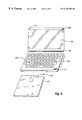
- FIG. 4 shows another embodiment of a PIU having the approximate dimensions of 6′′ ⁇ 5′′ ⁇ 0.75′′ and having a slot for physical attachment to a smart diskette, electrical contacts to exchange data with the smart diskette, a mechanism to operate a smart diskette switch and a battery;
- FIG. 5 shows an exemplary embodiment of a smart diskette
- FIG. 6 shows a read/write device having no drive or head motors for use with a smart diskette
- FIG. 7 a shows a smart diskette adapted to receive an IC smart-card, with battery 514 , converter (CONV), controller for magnetic interface 511 , processor 512 , memory chip 513 and a contact device 701 for chip card and recessed grip 704 for removing the chip card as well as a recess 700 where normally the drive for a magnetic disk is located.;
- FIG. 7 b shows a cross-section of the smart diskette of FIG. 7 a , with a recess for inserting a chip card and a recess 700 where normally the drive for a magnetic disk is located.;
- FIG. 8 a A Smartdiskette with battery 82 , converter 83 , controller for magnetic interface 85 and plugs 88 as data and current interface for the processor/storage board (memory card) as well as a recess 89 normally reserved for the drive for a magnetic disk;
- FIG. 8 b Cross-section of FIG. 8 a with lateral guide rails and a recess 89 normally reserved for a magnetic disk;
- FIG. 8 c Processor/memory card with external dimensions of a chip card but 2 mm thick with processor 86 , memory chip 87 , and plugs 88 as data and current interface to the frame of the Smartdiskette;
- FIG. 9 a Frame of the Smartdiskette with battery 92 , converter 93 , controller for magnetic interface 95 and plugs 98 as data and current interface for the processor/memory card;
- FIG. 9 b Cross-section of FIG. 9 a with lateral guide rails
- FIG. 9 c processor/memory card with external dimensions 60 mm ⁇ 55 mm ⁇ 3 mm with processor 96 , memory card 97 and plugs 98 as data and current interface to the frame of the Smartdiskette as well as a recess 99 where normally the drive for a magnetic disk is located;
- FIG. 9 d Cross-section of FIG. 9 c with appropriate side so that the processor/memory card can be inserted into the guide rails of the frame of the Smartdiskette as well as a recess 99 where normally the drive for a magnetic disk is located;
- FIG. 10 a Frame of the Smartdiskette with battery(s) 12 , and plugs 18 as a current interface to the processor/memory card as well as a recess 19 where normally the drive for a magnetic disk is located;
- FIG. 10 b Cross-section of FIG. 10 a with lateral guide rails
- FIG. 10 Processor/memory card with external dimensions of a chip card but 2 mm thick with processor 16 , memory chip 17 , and plugs 18 as data and current interface to the frame of the Smartdiskette as well as converter 13 and controller for magnetic interface 15 ;
- FIG. 11 a A Smartdiskette with battery 112 , converter 113 , controller for magnetic interface 115 , current generator consisting of rotor 120 , stator 121 , current regulator 122 , contact device 119 for mini-chip card 118 as well as recessed grip 123 for removing the mini-chipcard;
- FIG. 12 shows the invention used with a removable memory device, e.g., flash memory.
- a removable memory device e.g., flash memory.
- the “mini” PIU 100 has, for example, a slot 102 for physical attachment to a smart diskette 103 , electrical contacts 104 to exchange data with and/or provide power to the smart diskette 103 , a mechanism 105 to operate a switch 106 on the smart diskette 103 switch, and an optional battery (not shown).
- the switch 106 powers the smart diskette 103 when it is inserted into a drive or PIU device.
- the slot 102 may include detents therein which fit into corresponding recesses in the smart diskette 103 , for example, or other such conventional securing means, for removably securing the smart diskette 103 to the PIU 100 .
- the currently widespread liquid crystal display (LCD) technology provides an effective energy display for use with the PIU 100 .
- the PIU display 108 would incorporate conventional circuitry for driving the display 108 based on data transferred from the smart diskette 103 .
- display driving circuitry could be incorporated into the display 108 itself, or provided on the smart diskette 103 , if practical.
- a heartbeat detector would transmit pulses of data corresponding to a user's heartbeat via a wireless link to the mini PIU 100 and hence into the smart diskette 103 .
- the smart diskette 103 would store a continuous count of incoming heartbeats and use an on-board real-time clock (not shown) to calculate heart-rate at pre-progammed timing intervals.
- the user would subsequently insert the smart diskette 103 into a PC's standard 31 ⁇ 2′′ floppy disk drive and run an application program on the PC which would display the recorded heart-rate data and, for example, show comparisons with previous measurements.
- the optional display 108 and buttons 109 a user can have an immediate/continuous read-out of his/her heart rate on the PIU 100 .
- FIG. 4 shows another embodiment of a PIU 400 having, for example, the approximate dimensions of 6′′ ⁇ 5′′ ⁇ 0.75′′, with a slot 402 for physical attachment to a smart diskette 103 , electrical contacts and/or a magnetic transducer (not shown) as in the previously described embodiments to exchange data with the smart diskette 103 , a mechanism (not shown) to operate a smart diskette switch 106 , and an optional battery.
- FIG. 5 illustrates an exemplary smart diskette 103 for use with a PIU according to an embodiment of the present invention.
- a magnetic transducer 510 is electrically coupled to control/interface block 511 to accomplish data transfers to and from a corresponding read/write head in the PIU.
- the control/interface block 511 is further coupled to processor block 512 .
- Memory block 513 which represent RAM, ROM, EEPROM, Flash memory, etc., is coupled to the processor block 513 .
- Battery 514 supplies power via regulator 516 to the various components. Alternatively, power may be supplied through contacts 515 from the PIU, as previously described Also, data transfers may be accomplished through contacts 515 if the PIU does not provide a read/write head.
- Special purpose module block 517 represents the circuitry necessary to implement a special function, e.g., cellular telephone, pager, etc.
- FIG. 6 illustrates an exemplary read/write unit 610 , provided with contacts 104 , a read/write head 620 , and a control block 630 which is shown coupled to an external processor 640 .
- the illustrated embodiments are PIU's for use with a 31 ⁇ 2′′ sized smart diskette, however, a PIU which adapts to other sized smart diskettes, e.g., 2′′, 21 ⁇ 4′′ or 51 ⁇ 4′′ sized smart diskettes, for example, are considered within the scope of the present invention.
- the illustrated PIU embodiments accommodate a smart diskette in a slot engagement arrangement, other arrangements are also envisioned. Instead of a slot, the PIU could snap-fit onto a top surface of a smart diskette, for example.
- PIU's optionally include a battery
- other appropriate power sources may be provided instead of, or in conjunction therewith, for example, an array of solar cells could be provided on an upper surface of the PIU and/or smart diskette.
- the various transducers optionally provided are envisioned to include built-in microphones and speakers, and/or jacks for external microphones and speakers could be provided.
- Telephone and modem tone generators may be incorporated into the PIU's, as can be visible and infra-red light producing devices, and the like.
- a smart-card reader could be built into the smart diskette, such as illustrated in FIGS. 7 a , 7 b and 7 c , and disclosed in related U.S. Pat. No. 5,584,043.
- the Smartdiskette 103 shown in FIGS. 7 a and 7 b contains a 2-millimeter recess, in which a chip card 702 can be plugged in from the side alongside a contact device 701 which supplies the chip card 702 with current from the battery 514 and establishes a data link from the processor of the chip card 702 to the processor 512 of the Smartdiskette 103 .
- the Smartdiskette 103 contains a recess 700 on the bottom.
- the drive for a magnetic disk is normally located here.
- the chip card 702 shown in 7 c is a standard 0.8 millimeter thick chip card with processor and data memory. It also has contacts for supplying current from battery 514 of the Smartdiskette 103 and for establishing a data link from the processor of the chip card to processor 512 of the Smartdiskette 103 .
- the 8 c and 8 d contains in addition to the processor 86 , a data memory 87 as well as plugs 88 , in order to supply the Smartdiskette with current from battery 82 and to produce a data link from the processor 86 to the magnetic interface 85 of the Smartdiskette 81 .
- the 2 millimeter thick processor/memory card contains a data memory 87 and plugs 88 for the current supply from the battery 82 of the Smartdiskette and for establishing a data link from processor 86 to the magnetic interface 85 of the Smartdiskette 81 .
- the wide sides are tapered to 1 millimeter so that the card 810 can be plugged into the recess of the Smartdiskette 81 .
- the Smartdiskette 911 shown in FIGS. 9 a and 9 b has a cutout with a 1 millimeter wide groove to accommodate a 3 millimeter wide processor/memory card 912 alongside plugs 98 for supplying the processor/memory card 912 with current from the battery 92 and establishing a data link from processor 96 of card 912 to the magnetic interface 95 of the Smartdiskette 911 .
- the 3 millimeter thick processor/memory card shown in FIGS. 9 c and 9 d contains data memory 97 and plugs 98 for the current supply from the battery 92 of the Smartdiskette and for establishing a data link from processor 96 to the magnetic interface 95 of the Smartdiskette 911 .
- the Smartdiskette 113 shown in FIGS. 10 a and 10 b contains a 2 millimeter recess for the accommodation of a process/memory card with integrated magnetic interface 14 alongside plugs 18 for supplying card 114 with current from the battery 12 . Further, Smartdiskette 113 contains a recess 19 on the bottom. The drive for a magnetic disk is normally located here.
- the2 millimeter thick processor/memory card shown in FIGS. 10 c and 10 d contains a data memory 17 , converter 13 and controller for magnetic interface 15 , alongside plugs 18 for the current supply from the battery 12 of the Smartdiskette.
- the long sides are tapered to a width of 1 millimeter so that card 114 can be plugged into the recess of the Smartdiskette 113 .
- the Smartdiskette 1171 shown in FIG. 11 a contains a 1 millimeter recess, in which a chip card 118 can be plugged in from the side, and a contact device 119 for supplying the chip card 118 with current from battery 112 and for establishing a data link from the processor of the chip card 118 to the processor 116 of the Smartdiskette 1171 . Further the Smartdiskette 1171 contains recess 1119 on the bottom. The drive for a magnetic disk is normally located here. There is a recessed grip 123 for pulling out the mini-chip card 1 18 at the right-hand edge of the Smartdiskette 1171 .
- the chip card shown in FIG. 11 b is a standard 0.8 millimeter thick mini-chip card with processor and a data memory.
- the Smartdiskette includes battery 112 connected to a current generator comprised of rotor 120 , stator 121 , and a current regulator 122 .
- Memory card with integrated processor for checking an access code The memory is enable only if the access code is recognized as being correct.
- a portable safe data carder which can be carried comfortably in a purse or wallet, and which can communicate with any standard PC when it is plugged into the Smartdiskette.
- a wide variety of security related features may be provided by appropriate programing and/or configuring of the smart diskette and/or PIU.
- a PIU could be provided with a ROM containing a security code which would render it useless with a smart diskette which does not have a corresponding code.
- the smart diskette could prompt a user for an identification code upon insertion into a PIU, and deny access unless the correct code is entered on the PIU keyboard/keypad.
- the PIU with inserted smart diskette could function to provide an electronic spread-sheet, a perpetual calendar, a telephone directory, a word-processor, entertainment (game) programs, English-foreign language dictionary, financial calculator, stock quote and/or analysis, or any other of the multitude of applications currently available for desk-top and notebook computers.
- a scanner for scanning written documents into memory or a micro camera ( 410 in FIG. 4) for providing video image storage and/or transmission over cellular telephone, for example.
- a PIU equipped with an audio or video input device could be used to provide secret monitoring of an area
- a smart diskette could be programmed to periodically record in its memory, for example, once a minute, a snapshot of audio or video input from such a PIU. Subsequently, the smart diskette would be removed and the snapshots retrieved into a personal computer by security personnel for analysis.
- a PIU with a bar code reader could be used in inventory applications. For example, inventory bar codes would be scanned and/or keyed in, and stored in the memory on the smart diskette. Subsequently, the smart diskette could be removed from the PIU and inserted in an inventory control computer's 31 ⁇ 2′′ disk drive for retrieval and processing.
- the PIU with smart diskette configured with microphone 408 and speech recognition software/module could function as a speaker recognition system, i.e., a system which recognizes and/or verifies a particular person (speaker) producing the speech. The verification could be used to obtain access to the PIU functionality.
- a PIU equipped with a keypad, display and loud-speaker could be used as an aid for speech-impaired individuals, where words and/or phrase codes could be keyed in, and spoken text accessed on the smart diskette and output through the loud-speaker.
- Conventional text to speech circuitry could be provided on the smart diskette in the special purpose module 517 , and/or software in memory 513 , for such an application.
- the PIU keypad could further incorporate a Braille keyboard for use by sight-impaired individuals.
- Foreign language keyboards could be enabled through software and/or be provided as specific PIU's.
- Specific medical information about an individual could be stored on a smart diskette, and medical personnel could access the information in an emergency either through a PIU or a hospital computer's 31 ⁇ 2′′ disk drive.
- a smart diskette could be labeled with the international red cross symbol, or the like, identifing it as containing vital medical information.
- Such information could be stored in the smart diskette in any or all of the major languages for use when traveling abroad.
- Emergency contacts such as family or medical specialists to contact in case of an emergency could be stored therein as well.
- a panic button or emergency code could be provided on the PIU which would direct the smart diskette with PIU to automatically call emergency personnel. If also equipped with a heart rate monitor, in case of irregular heart beats, or other abnormal heart activity indicative of a medical emergency, the smart diskette could be programmed to call emergency personnel automatically.
- the smart diskette could be loaded with bank transaction software and/or a specially configured PIU provided so that banking activities could be readily accomplished remotely.
- security features such as are used conventionally in remote banking would be naturally provided.
- a PIU with appropriately programmed smart diskette could be used as an electronic answer sheet.
- each test taker would be given an appropriately programmed smart diskette and PIU.
- the PIU would be provided with a display and numeric or alpha-numeric keypad.
- the smart diskette would be programmed to prompt the test taker for his/her unique identification number, such as a social security number or student ID number.
- the smart diskette After entering and verifying the ID as being associated with a bonafide student, the smart diskette would prompt the test-taker to open the test booklet and begin the test. The smart diskette with PIU would then display something like “Q1?” and wait for the test-taker to input the number corresponding to his/her answer selection for the first question. When the first answer is entered, the smart diskette would record the answer in its memory and display a prompt for the next question. A built in timer could be provided which would end the test after a pre-programmed time had elapsed.
- test-takers After the test had been completed, the test-takers would turn-in their smart diskettes and PIU's. To grade the test, the test-giver would simply remove each smart diskette from its PIU, and insert each smart diskette into the 31 ⁇ 2′′ disk drive of a personal computer programmed to access the test-taker's ID and answers, and determine a raw score.
- the personal computer After loading all the test-takers' data, the personal computer could readily identify questions which should be discarded or discounted because all test takers missed them, for example.
- the personal computer could calculate mean and median scores, assign grades, etc. With such a device, grading errors due to stray or light pencil marks, for example, associated with paper answer sheets would be eliminated. Additionally, special purpose and expensive test reading devices would be eliminated since the ubiquitous personal computer programmed to access the smart diskettes through its 31 ⁇ 2′′ disk drive would be used.
- the present display technology e.g., liquid crystal display (LCD)
- LCD liquid crystal display
- the present invention contemplates incorporation of new display technologies as they arise for the PIU display.
- the PIU's can be configured to incorporate such new keyboards.
- FIG. 12 shows yet another exemplary embodiment of the invention, in particular where the user removable memory device 1202 comprises only memory, e.g., flash memory, and connectors, i.e., there is no significant processor power on the card 1202 .
- the removable memory device 1202 is the type that is typically used in digital cameras, for example.
- the insertable frame is designed to fit into a personal computer (PC) disk drive, e.g., a 31 ⁇ 2′′ diskette drive, and interface therewith through the transducer, as illustrated.
- the transducer is coupled to an interface circuit coupled to an ASIC cirucit, and is under the control of a processor, e.g., a 6805 processor, or the like. Power is supplied via one or more batteries and a DC-DC converter.
- PC personal computer
- Data can be read from or written to the memory of the removable memory device with the illustrated embodiment
- Digital signals from the memory device can be converted to an analog signal, e.g., MFM, and a standard floppy drive can be used to transfer the information to a PC.
- MFM analog signal
- a standard floppy drive can be used to transfer the information to a PC.
- Pictures taken with a digital camera and stored on a removable memory device could thus be transferred to a personal computer for editing and the like.
- Firmware on this embodiment coordinates with its ASIC to read the digital information from a removable memory device and convert it to the MFM signal to be transferred to the PC through the floppy drive.
- the picture data so transferred in this embodiment may appear to the computer user as standard a JPEG picture format file, for example, on a standard floppy diskette.
- the user can access the pictures on the removable memory device using the standard disk operations of the operating system of the PC.
- the user can, for example, read or write to the memory, get a directory of the pictures on the memory device, copy, delete, and view with a standard PC picture viewer, etc., just as if using a standard floppy diskette.
- Insertable memory devices may store on the order of 2 to 16 megabytes or more.
- audio and multimedia data could be transferred to a PC using this embodiment, for example.
- the memory module could be used to provide a hard disk backup, or to transfer data from one PC to another, as would be apparent to one skilled in the art.
- the 6805 allows only 8 significant character variable and function names. We can follow the conventions used in SDOS code for FlashDisk code (replacing the ‘S’ for SDOS with ‘F’ for FlashDisk).
- Functions and variable names are of upper and lower case using upper case to indicate the start of each word (or abbreviated word) within the name—i.e. not using underscores.
- the low level magnetic comms software is implemented as a state machine comprising three output track control loops and two input data functions. Each control loop corresponds to a state of the state machine.
- the request and response buffers share the same 102 bytes of memory. This means that a request from the PC will overwrite the previous response.
- the request and response buffers have the same format.
- the service data bytes (d0 to d52) are contained within the protocol data bytes (p0 to p53) as follows:
- p1 Message sequence number (incremented by the FlashDisk);
- p4 to p52 d1-d48 Service Data
- p53 to p54 CRC over p0 to p52 inclusive
- checksum byte FvChk For each of the 512 bytes of data. that come in add them to the checksum byte FvChk. This is a global checksum over the whole data transaction (max 16 sectors) which is reset and checked by the service routines.
- Set PB 4 (ENCSRC) to indicate that the next byte should be taken from the data and set to transmit (set PB 0 ).
- These functions trnmit the various headers for a floppy disk track. They use instruction timed code to send the bytes to the MFfM encoder at the correct time. With ENCSRC set the MFM encoder gets bytes from the CPU data bus at 16 us intervals. Within the 16 us there is an 8 us windows (the ‘safe period’) when it is safe to change the state of the data bus i.e. the previous byte has been taken by the encoder.
- the x reg contains an offset into a table in ROM of sector header data.
- Input data is expected, so call FTxSecHd to send the input sector header, clear RX/ ⁇ RX (PB 0 ), reset the count FvNumSecs and call FInCPU to test for input data.
- FChkSet will reset the checksum bytes FvCRC1 and FvCRC2.
- FCRCByte will add the byte in a reg to the current running CRC held in FvCRC1 & FvCRC2.
- CRC checking is performed on the protocol buffer as it arrives by calling FCRCBuff. Due to time constraints it is not possible to check the data CRC for a whole sector sent by the PC. Instead a single byte checksum is sent with each written request. This checksum is a simple addition over the whole of the data (upto 16 sectors). The addition is carried out while the data is transferred to the RAM by the MFM decoder (in FInFlash). The checksum initialisation and checking is carried out by the write service (FhWrite) and the FNextWr function respectively.
- Is called from the Idle output loop when a service request message comes in. Uses a lookup table to associate the service request codes in the request/response buffer with the appropriate service handler functions. Jump to the function (if found) or jump to an error handler function (FhError) if not found.
- Each service will also set FvState to indicate which state to go into -FIDLE, FREAD or FWRITE.
- FvWrSec will always contain the (floppy disk) sector number which the PC can write to
- FvWrSHdr will always point to the sector header data for this sector number in ROM.
- the read services will set up an array of flash page addresses to read from.
- the FvFPPtr variable will point to the current flash page number in CPUm RAM and will be incremented by the FNextRd function every time it is called. This means that the read data output loop simply has to know how many sectors are to be output FvRdSecs) and to call FNextRd during the padding characters of the sector header preceding the data
- the read services should all therefore set offset 1 of the response buffer to the number of sectors to be read from Flash and FvFPPtr to point to the first page number in the page list FvState should be set to FREAD so that once FService will pass control on to the read data output loop once it has completed the information in the status response message.
- FvRdSecs to be 8 sectors i.e. one block
- the write data services will set up a sequence of flash pages to write to in the same manner as the read data services.
- This array is interpreted by FNextWr which is called by the write data output loop after it has successfully received a sector of data from the PC.
- FNextWr is responsible for copying the data from the RAM device into Flash after it has been received by the FInFlash function.
- the Flash destination address is checked to see if the block is already in RAM. If it isn't then the previous block (if there is one) is written from the RAM to the Flash and the complete block which contains the next required page is loaded from Flash into the RAM. The erase operation on the block is the started and continues while the page is read from the decoder.
- the RAM address is set to the position within the loaded block where the next page will go.
- the first two tails in a given block contain information about the data that is stored in the block (i.e. the sector to Flash page mapping and the usage count). If this is the first time the block has been written to (i.e. the FORMATED byte in the tail is ffh), then FNextWr will initialise the tail data for the block when it is loaded into RAM.
- FNextWr will call FRemapWr to load the Remap Block number from the ERP tail and write the failed block data to it (and update the tails and make an entry in the ERP table).
- the Remap block is a Flash block previously designated for such emergencies by the PC and must be present before a write is allowed by the FlashDisk.
- a checksum over all the data in the sectors (upto 16) is sent with the service request. This is initialised by the service routine, updated as data arrives by FInFlash and checked by FNextWr.
- Set response buffer offset 1 to 7 to indicate the number of sectors to be written after the initial one.
- This function is called initially from the write sectors service handler and then from the write data output loop.
- bit 7 of FWrState is set (i.e. previous error) then goto P;
- bit 4 of FWrState indicates this is not an absolute write then
- This flinction sets up the next RAM transfer address and if necesssry reads the appropriate block into RAM from flash.
- bit 0 of FvRdStat is clear then read the block indicated by the FP pointed to by FvFPPtr into the RAM, set bit 0 of FvRdStat and set the RAM address to the requested page.
- FvRdStat If bit 0 of FvRdStat is set then compare the block indicated by the FP pointed to by , FvFPPtr with the previous FP in the list (if FvFPPtr is at the start of the list then compare it with the value at the end of the list). If they are different then read the block indicated by the FP pointed to by FvFPPtr into the RAM. (This may be simplified if a variable is used to store the block number of the current block in RAM).
- FFlAdr1 Chip number (starting from 1) of chip to activate.
- FvFlAdr1 The chip number to select.
- FvFlAdr2 (2 bytes)—The 2 byte Flash page address.
- FvFlAdr1 Flash chip number
- FvFlAdr2 (2 bytes)—Flash page address.
- FvFlAdr1 Flash chip number.
- FvFlAdr2 (2 bytes)—Flash page address.
- FvFlAdr1 Flash chip number
- FvFlAdr2 (2 bytes)—Flash page address.
- FvFlAdr1 Flash chip number
- FvFlAdr1 Flash chip number
- FvRAMAdr a two byte RAM address.
- a reg The number of byes to write.
- a reg The number of byes to write.
- FvFPPtr Points to the 3 byte Flash address.
- FvRAMAdr The two byte RAM address.
- the time in this routing (including entrance/exit code) is ((x*16) ⁇ 8)us.
- FvFlTail The 16 byte tail.
- FvFlTail The 16 byte tail.
- FvFlTail The 16 byte tail.
- FVCRC1 and FvCRC2 The two byte CRC result.
- FvFlAdr1 Flash chip number
- FvFlAdr2 (2 bytes)—Flash page address.
- FvFlAdr1 Flash chip number
- FvFlAdr2 (2 bytes)—Flash page address.
- x reg Pointer to storage for the 3 byte sector number.
- x reg Pointer to the 3 byte sector number.
- FvFlAdr1 Flash chip number
- Fvf1Adr2 (2 bytes)—Flash page address.
- mapping module Functions in the mapping module are responsible for performing the translation from FlashDisk sector numbers to absolute flash page addresses and for dealing with remapping write failures.
- Byte 13 ERAS Indicates if the block is formatted.
- Each entry in the ERP consists of,
- Flash address (chip number then page address) of Flash block that contains the 8 sectors starting from the on given in bytes 0-2.
- All unused entries must have at least the byte 0 set to FFh as this indicates the end of used the ERP entries.
- Each ERP contains 42 of these entries, with the remaining 4 bytes of the page being skipped. Thus there are a maximum of 672 entries in the ERP block.
- Bytes 1-3 of the request buffer contain the sector number.
- FvFlAdr2 (2 bytes)—page address.
- FChkT1 to check the tails checksum If the block is unformatted then return the address just calculated as being the address for the requested sector. If the checksum is wrong then the block is assumed to be bad and thus FMapEek is called to look in the ERPs for an entry for the sector number. If there is one then the Flash address given with that entry is returned.
- Bytes 1-3 of request buffer contain the sector number.
- FvFlAdr1 Chip number of Flash address.
- FvFlAdr2 (2 bytes)—Page address.
- Group 1 the block has been remapped before (indicated by the 1st byte of the SEC entry in the tail being set to FFh) i.e. it was used when a previous block failed and has itself now failed.
- the two cases of this group depend on the state of the tail at the address pointed to by the FP entry in the failed block's tail (FPt).
- Group 2 The block has not previously been remapped. The two cases of this group depend on whether the block has been swapped with another block, and thus the actual data in the failed block is not for the sector that directly relates to its Flash address, it is the data for the block pointed to by the FP entry in the block's tail. This can be determined by calculating the Flash address that directly corresponds to the sector number contained in the SEC entry of the failed block's tail. If this address matches the actual address of the failed block then the block has not been swapped.
- the block has not been swapped. Add the sector number in the SEC entry of the failed block's tail to the ERPs with the Flash address of the Emergency Remap Block.
- the block has been swapped. Add the sector number that directly corresponds to the failed block's address to the EPRs with the Flash address in the FP entry of the failed block's tail. Load the block pointed to by the FP entry in the failed block's tail and updates its tail with the Flash address of the Emergency Remap Block.
- This routine is used by the PC to send the FlashDisk a sector number which can be used by the remapping functions when a writ fails. Note that the PC sends a sector number and as such it is possible that the sector has itself been remapped or swapped.
- the tail will contain all that is necessary to store in the ERP block. If the block has been remapped then the FP entry will contain the Flash address of the block it was moved to (which is the block we actually want), and if not the FP entry will contain the FP of the block we have just loaded (again what we want). Thus FWrERPT1 can be called to write the tail to the ERP block and then FRam2ERP can be called to write the ERP block back to Flash.
- This function recalculates the tail checksum and the ERP check byte then attempts to write the block to the primary ERP block first. If this fails it is written to the backup block.
- the address variables FvFlAdr1 and FvFlAdr2 must be preserved.
- x reg Points to sector number to add.
- FvFlAdr1 Chip number of Flash address to add.
- FvFlAdr2 (2 bytes)—Page address of to add.
- x reg Points to sector number to search for.
- the checksum is over all bytes except the last byte of each page and the tail bytes.
- the checksum result is stored in the last byte of the last page of the block and also returned in FvERPChk.
- the FlashDisk will be bootable and contain a small program to intal the device driver. This is possible by the transmission of 5 hard coded sectors from ROM. These sectors will star from is sector 1 (the boot sector) which will, if booted on, call the hard disk boot sector. Following this are two sectors of FAT (sectors 2 & 3), then a one sector root directory (sector 4) and finally a one sector install program (sector 5).
- the install program is the only entry in the FAT and root directory. This will appear as drive A: to the PC. Thus typing A:INSTALL will run the intal program which is a simply boot strap program which loads a larger program from a reserved area of Flash (sectors 1 to 16 of the FlashDisk are configured as reserved in the boot record). This larger program will copy the device driver from the Flash (in the area immediately after the program itself) and update the config.sys.
- This layer is responsible for interacting with the FlashDisk via Int 13h. It will be responsible for sequence number and CRC checking of the response buffer and recovery of these errors.
- this function simply returns the error code in the event of such errors.
- the FlashDisk should then be outputting a sequence of the appropriate sector headers to write to.
- FDPv_Request_buffer Initialised with the required service code and data.
- ES:BX Pointer to buffer containing data.
- FDPv_Request_buffer Initialised with the required service code and data.
- ES:BX Pointer to a buffer to put the data.
- BIOS Uses the BIOS to write sectors to the FlashDisk. If a disk changed error is detected the fdpv_disk_changed flag is set.
- FDPv_Request_buffer Buffer for which CRC must be calculated.
- This layer receives a request for an arbitrary number of sectors, which it must split into the 16 sector blocks required by the protocol layer. It will also be responsible for formulating the required request in the Request buffer.
- Another responsibility of this layer is to manage the sending of new Emergency Remap Blocks when the FlashDisk signals that it has used its remap block.
- Emergency Remap Blocks are unused clusters (8 sectors) that have been marked as bad in the FAT by the device driver. They can then be sent to the FlashDisk for use when another block fails. In an attempt to make write errors transparent to DOS the device driver should be able to deal with them without returning to DOS. Because it is not possible to update the FAT while in the middle of a write, the device driver must gather and store a number of sectors that it can use as remap blocks before the write is started.
- the format of the data stored in the remap block sector is as follows,
- New remap blocks from the FAT are then added over the top i.e. the system is first in-last out.
- dword Pointer to data buffer.
- dword Pointer to data buffer.
- dword Pointer to buffer containing 16 sectors of block data.
- dword Pointer to buffer containing 16 bytes of tail data.
- dword Pointer to buffer to receive 16 sectors of block data.
- dword Pointer to buffer to receive 16 bytes of tail data.
- DS:SI points to a request/response buffer
Abstract
Description
| p0 | = FDh = FlashDisk Message ID (or DFh on outgoing |
| messages after a threshold switch) | |
| p1 | = Message sequence number (incremented by the FlashDisk); |
| p2 | = Sector number which the PC can currently write to |
| p3 | = d0 Service number (request)/result code (response) |
| p4 to p52 | = d1-d48 Service Data |
| p53 to p54 | = CRC over p0 to p52 inclusive |
| Test | FhTest | ||
| Read sectors | FhRead | ||
| Read absolute block + tail | FhAbsRd | ||
| Read tails | FhRdT1 | ||
| Write sectors | FhWrite | ||
| Write absolute block + tail | FhAbsWrt | ||
| Write tail | FhWrtT1 | ||
| Erase all Flashh | FhErasAll | ||
| Install new remap block | FhNewRBlk | ||
| Initialise FlashDisk | FhInitF1 | ||
| FlashDisk information | FhInfo | ||
| Reads the temperature | FhTemp | ||
| ah = 1 (Disk not changed) | ||
| = 0 (Don't know) | ||
| = −1 (Disk Changed) | ||
Claims (32)
Priority Applications (2)
| Application Number | Priority Date | Filing Date | Title |
|---|---|---|---|
| US09/333,997 US6325291B1 (en) | 1994-04-19 | 1999-06-16 | Apparatus and method for transferring information between a smart diskette device and a computer |
| US09/512,328 US6340117B1 (en) | 1994-04-19 | 2000-02-24 | Apparatus and method for transferring information between a removable memory and a computer |
Applications Claiming Priority (5)
| Application Number | Priority Date | Filing Date | Title |
|---|---|---|---|
| US08/170,166 US5584043A (en) | 1991-06-26 | 1992-06-16 | Apparatus having a smart card accomodated by a diskette frame containing processor memory and battery power for interfacing with a standard diskette drive |
| US08/514,382 US6042009A (en) | 1991-06-26 | 1995-08-11 | Transfer device for transferring data between an electronic data processing device and an electronic card |
| US3667297P | 1997-03-11 | 1997-03-11 | |
| US08/867,496 US6089459A (en) | 1992-06-16 | 1997-06-02 | Smart diskette device adaptable to receive electronic medium |
| US09/333,997 US6325291B1 (en) | 1994-04-19 | 1999-06-16 | Apparatus and method for transferring information between a smart diskette device and a computer |
Related Parent Applications (1)
| Application Number | Title | Priority Date | Filing Date |
|---|---|---|---|
| US08/867,496 Continuation US6089459A (en) | 1991-06-26 | 1997-06-02 | Smart diskette device adaptable to receive electronic medium |
Related Child Applications (1)
| Application Number | Title | Priority Date | Filing Date |
|---|---|---|---|
| US09/512,328 Division US6340117B1 (en) | 1994-04-19 | 2000-02-24 | Apparatus and method for transferring information between a removable memory and a computer |
Publications (1)
| Publication Number | Publication Date |
|---|---|
| US6325291B1 true US6325291B1 (en) | 2001-12-04 |
Family
ID=27488384
Family Applications (3)
| Application Number | Title | Priority Date | Filing Date |
|---|---|---|---|
| US09/333,997 Expired - Fee Related US6325291B1 (en) | 1994-04-19 | 1999-06-16 | Apparatus and method for transferring information between a smart diskette device and a computer |
| US09/421,072 Expired - Fee Related US6315207B1 (en) | 1991-06-26 | 1999-10-19 | Smart diskette device adaptable to receive electronic medium |
| US09/512,328 Expired - Fee Related US6340117B1 (en) | 1994-04-19 | 2000-02-24 | Apparatus and method for transferring information between a removable memory and a computer |
Family Applications After (2)
| Application Number | Title | Priority Date | Filing Date |
|---|---|---|---|
| US09/421,072 Expired - Fee Related US6315207B1 (en) | 1991-06-26 | 1999-10-19 | Smart diskette device adaptable to receive electronic medium |
| US09/512,328 Expired - Fee Related US6340117B1 (en) | 1994-04-19 | 2000-02-24 | Apparatus and method for transferring information between a removable memory and a computer |
Country Status (1)
| Country | Link |
|---|---|
| US (3) | US6325291B1 (en) |
Cited By (8)
| Publication number | Priority date | Publication date | Assignee | Title |
|---|---|---|---|---|
| US6755345B2 (en) | 2002-07-10 | 2004-06-29 | Golf Reporting Solutions, Llc | Golf handicap smart card system |
| US6955292B2 (en) * | 2002-07-02 | 2005-10-18 | Canon Kabushiki Kaisha | Media reader for a removable digital storage medium |
| US20050230483A1 (en) * | 2004-04-16 | 2005-10-20 | Miller Robert C | Memory card with two standard sets of contacts and a contact covering mechanism |
| US20050230484A1 (en) * | 2004-04-16 | 2005-10-20 | Cuellar Edwin J | Memory cards having two standard sets of contacts |
| US20060144938A1 (en) * | 2005-01-05 | 2006-07-06 | Donna David | Wine data scanner, related database system and method of using same |
| US7092256B1 (en) | 2002-04-26 | 2006-08-15 | Sandisk Corporation | Retractable card adapter |
| US20070247757A1 (en) * | 2004-06-17 | 2007-10-25 | Koninklijke Philips Electronics, N.V. | Customizable Cartridge for Protecting a Readable and/or Writable Data Storage Medium |
| US20080030963A1 (en) * | 2005-08-02 | 2008-02-07 | Warren Middlekauff | Memory Card With Latching Mechanism for Hinged Cover |
Families Citing this family (22)
| Publication number | Priority date | Publication date | Assignee | Title |
|---|---|---|---|---|
| FR2805635B1 (en) * | 2000-02-24 | 2003-12-12 | Mitsubishi Electric France | CARD READER AND MOBILE EQUIPMENT COMPRISING SAME |
| JP4649009B2 (en) | 2000-03-08 | 2011-03-09 | 株式会社東芝 | Information processing apparatus having a card interface, card-type electronic equipment that can be mounted on the apparatus, and operation mode setting method in the apparatus |
| JP2001266096A (en) * | 2000-03-17 | 2001-09-28 | Sony Corp | Recording medium using nonvolatile memory and data transfer method |
| US7295443B2 (en) | 2000-07-06 | 2007-11-13 | Onspec Electronic, Inc. | Smartconnect universal flash media card adapters |
| US6561420B1 (en) * | 2000-10-18 | 2003-05-13 | Erica Tsai | Information card system |
| US8403228B2 (en) | 2001-05-15 | 2013-03-26 | Inadam Corporation | Computer readable universal authorization card system and method for using same |
| US7810735B2 (en) | 2001-05-15 | 2010-10-12 | Inadam Corporation | Computer readable universal authorization card system and method for using same |
| US7299980B2 (en) | 2001-05-15 | 2007-11-27 | Inadam Corporation | Computer readable universal authorization card system and method for using same |
| US20040039876A1 (en) * | 2002-08-21 | 2004-02-26 | Nelson James R. | Portable mass memory device with memory card reader |
| US20040054846A1 (en) * | 2002-09-16 | 2004-03-18 | Wen-Tsung Liu | Backup device with flash memory drive embedded |
| US20040197744A1 (en) * | 2003-03-03 | 2004-10-07 | Roopa Basu | Educational calendar |
| JP2004362731A (en) * | 2003-05-12 | 2004-12-24 | Sony Computer Entertainment Inc | Disk cartridge and device to which disk cartridge is loaded |
| US20050035200A1 (en) * | 2003-08-11 | 2005-02-17 | Colin Hendrick | Secure smartcard sleeve |
| US20050077348A1 (en) * | 2003-08-11 | 2005-04-14 | Colin Hendrick | Intelligent ID card holder |
| US8484671B1 (en) | 2003-10-07 | 2013-07-09 | The Directv Group, Inc. | Receiver interface with multiple access cards |
| WO2005106672A2 (en) * | 2004-04-21 | 2005-11-10 | Storcard, Inc. | Hierarchical storage management of encrypted data files |
| WO2005109887A1 (en) * | 2004-04-23 | 2005-11-17 | Smart Metric, Inc. | Smartcard with visual display |
| JP2009086955A (en) * | 2007-09-28 | 2009-04-23 | Toshiba Corp | Camera apparatus and control method thereof |
| KR101023904B1 (en) | 2008-10-21 | 2011-03-22 | 삼성에스디아이 주식회사 | Ic card with external battery |
| CN102270016B (en) * | 2010-06-07 | 2013-11-20 | 鸿富锦精密工业(深圳)有限公司 | Cloud computing client computer |
| US9972930B1 (en) | 2017-01-16 | 2018-05-15 | Methode Electronics, Inc. | Transceiver module wit flex circuit |
| TWI797464B (en) * | 2020-07-28 | 2023-04-01 | 群聯電子股份有限公司 | Data reading method, memory storage device and memory control circuit unit |
Citations (10)
| Publication number | Priority date | Publication date | Assignee | Title |
|---|---|---|---|---|
| US4499510A (en) * | 1982-08-03 | 1985-02-12 | Weltec Digital, Inc. | Precision alignment system for information storage devices |
| US4837628A (en) * | 1986-07-14 | 1989-06-06 | Kabushiki Kaisha Toshiba | Electronic still camera for recording still picture on memory card with mode selecting shutter release |
| US4890179A (en) | 1987-02-27 | 1989-12-26 | Baker James W | Magnetic tape backup device for use with a floppy disk drive |
| US4891727A (en) * | 1986-12-18 | 1990-01-02 | Mitsubishi Denki K.K. | Memory device |
| US5438359A (en) * | 1992-09-16 | 1995-08-01 | Asahi Kogaku Kogyo Kabushiki Kaisha | Electronic camera system using IC memory card |
| US5844757A (en) * | 1995-10-18 | 1998-12-01 | Rose; David H. | Personal computer data storage card and method for transferring information between the data storage card and personal computers |
| US5877975A (en) * | 1996-08-13 | 1999-03-02 | Nexcom Technology, Inc. | Insertable/removable digital memory apparatus and methods of operation thereof |
| US5887145A (en) * | 1993-09-01 | 1999-03-23 | Sandisk Corporation | Removable mother/daughter peripheral card |
| US6042009A (en) | 1991-06-26 | 2000-03-28 | Smartdiskette Gmbh | Transfer device for transferring data between an electronic data processing device and an electronic card |
| US6089459A (en) | 1992-06-16 | 2000-07-18 | Smartdiskette Gmbh | Smart diskette device adaptable to receive electronic medium |
Family Cites Families (73)
| Publication number | Priority date | Publication date | Assignee | Title |
|---|---|---|---|---|
| US550709A (en) | 1895-12-03 | Bicycle-top | ||
| US3700826A (en) | 1972-01-17 | 1972-10-24 | Donald V O Neal | Multi-track adapter cartridge adapter unit for a multi-track cartridge type magnetic tape player |
| US3978524A (en) | 1974-09-03 | 1976-08-31 | Bernard Gordon | Adapter for playing remotely located electronic apparatus through a magazine tape recorder/reproducer |
| US3940758A (en) | 1974-09-20 | 1976-02-24 | Margolin George D | Expandable keyboard for electronic pocket calculators and the like |
| US3946156A (en) | 1974-10-29 | 1976-03-23 | Budrose Charles R | Adapter for recording-reproducing machine |
| US4034164A (en) | 1975-08-25 | 1977-07-05 | Westmoland Randy C | Citizens band cartridge for tape decks |
| US4228474A (en) | 1978-11-13 | 1980-10-14 | Neal Jr Roy L | Adapter unit for translating electrical signals |
| US4504871A (en) | 1980-01-08 | 1985-03-12 | Verbatim Corporation | Magnetic media test fixture apparatus |
| NZ199968A (en) | 1981-03-11 | 1985-10-11 | Wellcome Found | Benzoic acid derivatives and naphthoic acid derivatives and pharmaceutical compositions |
| US4446519A (en) | 1981-05-26 | 1984-05-01 | Corban International, Ltd. | Method and apparatus for providing security for computer software |
| JPS6084686A (en) | 1983-10-17 | 1985-05-14 | Toshiba Corp | Recording system of information recording medium |
| JPS6087405A (en) | 1983-10-20 | 1985-05-17 | Matsushita Electric Ind Co Ltd | Floppy disk device |
| US4575621A (en) | 1984-03-07 | 1986-03-11 | Corpra Research, Inc. | Portable electronic transaction device and system therefor |
| JPS6169266A (en) | 1984-09-12 | 1986-04-09 | Sharp Corp | Input device |
| JPS6194134A (en) | 1984-10-13 | 1986-05-13 | Naretsuji:Kk | Radio mouse device |
| CH664635A5 (en) | 1984-11-14 | 1988-03-15 | Sodeco Compteurs De Geneve | Pencil-shaped cassette for cash-less payment - has optically-readable markings representing amounts of money on moving tape |
| DE3534638A1 (en) | 1984-11-23 | 1986-05-28 | Mahmoud 5460 Linz Zahran | Patient data card |
| JPH0734215B2 (en) | 1985-02-27 | 1995-04-12 | 株式会社日立製作所 | IC card |
| US4860128A (en) | 1985-04-24 | 1989-08-22 | Nintendo Co., Ltd. | Recordable data device having identification symbols formed thereon and cooperating data processing system having registering symbols |
| US4701601A (en) | 1985-04-26 | 1987-10-20 | Visa International Service Association | Transaction card with magnetic stripe emulator |
| DE3528199A1 (en) | 1985-08-06 | 1987-02-19 | Glory Kogyo Kk | Automatic issuing machine for cheque cards |
| US4734897A (en) | 1985-11-13 | 1988-03-29 | Recoton Corporation | Cassette adapter for playback device, such as a compact disk player |
| NL8503410A (en) | 1985-12-11 | 1987-07-01 | Philips Nv | DEVICE FOR TRANSFERRING INFORMATION BETWEEN AN ELECTRONIC MEMORY CARD AND A DATA PROCESSING UNIT. |
| JPH0615273B2 (en) | 1986-01-20 | 1994-03-02 | 株式会社アイテイテイキャノン | IC card |
| US4791283A (en) | 1986-06-03 | 1988-12-13 | Intellicard International, Inc. | Transaction card magnetic stripe emulator |
| US4769764A (en) | 1986-08-11 | 1988-09-06 | Isaac Levanon | Modular computer system with portable travel unit |
| US4774618A (en) | 1986-09-15 | 1988-09-27 | Abiel Raviv | Method of and apparatus for storing and returning information on a business card |
| EP0266101B1 (en) | 1986-10-16 | 1991-05-15 | Hitachi Maxell Ltd. | Composite memory device |
| US4951249A (en) | 1986-10-24 | 1990-08-21 | Harcom Security Systems Corp. | Method and apparatus for controlled access to a computer system |
| DE8709268U1 (en) | 1987-07-04 | 1987-09-03 | Walter, Bernhard, 7500 Karlsruhe, De | |
| DE3804361C1 (en) | 1988-02-12 | 1988-09-29 | Deutsche Bundespost, Vertreten Durch Den Praesidenten Des Fernmeldetechnischen Zentralamtes, 6100 Darmstadt, De | |
| CA1321649C (en) | 1988-05-19 | 1993-08-24 | Jeffrey R. Austin | Method and system for authentication |
| FR2632752B1 (en) | 1988-06-08 | 1991-12-06 | Parienti Raoul | MEMORY BI-MODULE CHIP CARD |
| US5015830A (en) | 1988-07-04 | 1991-05-14 | Sharp Kabushiki Kaisha | Electronic card reading device |
| JPH0720781Y2 (en) | 1988-07-06 | 1995-05-15 | ティーディーケイ株式会社 | Cassette type recording body |
| US4959861A (en) | 1988-07-13 | 1990-09-25 | Howlette Edward L | Security system for computer software |
| US5296692A (en) | 1988-10-24 | 1994-03-22 | Sharp Kabushiki Kaisha | IC card adapter for use in memory card slot with or without superimposed memory card |
| US5224216A (en) | 1988-10-28 | 1993-06-29 | Gordon Alastair T | Computer diskette drive communication interface |
| US4965691A (en) | 1988-11-14 | 1990-10-23 | Syquest Technology | Sealed removable cartridge for use with a high density disc drive with magnetic clutch |
| DE3903454A1 (en) | 1988-12-12 | 1990-06-13 | Raymund H Eisele | ELEMENT INSERTABLE IN IT FACILITIES |
| JPH02161670A (en) | 1988-12-14 | 1990-06-21 | Toshiba Corp | Adapter for 5-inch floppy disk |
| US5247164A (en) | 1989-01-26 | 1993-09-21 | Hitachi Maxell, Ltd. | IC card and portable terminal |
| JP3167303B2 (en) | 1989-06-28 | 2001-05-21 | 株式会社東芝 | Personal computer |
| FR2651347A1 (en) | 1989-08-22 | 1991-03-01 | Trt Telecom Radio Electr | SINGLE NUMBER GENERATION METHOD FOR MICROCIRCUIT BOARD AND APPLICATION TO COOPERATION OF THE BOARD WITH A HOST SYSTEM. |
| US5050020A (en) | 1989-11-09 | 1991-09-17 | Archive Corporation | Cartridge loader for loading each of a plurality of cartridges into a cartridge insertion slot |
| US5423054A (en) | 1989-12-29 | 1995-06-06 | Pitney Bowes Inc. | Processor and read/write head incorporated in disk for communicating data to host directly from processor read/write head to read/write head of host disk drive |
| US5044798A (en) | 1990-01-18 | 1991-09-03 | William H. Roylance | Compressible/expandable keyboard with adjustable key spacing |
| JP2765745B2 (en) | 1990-02-09 | 1998-06-18 | レーム プロパティズ ビーブイ | IC card adapter |
| US5204663A (en) | 1990-05-21 | 1993-04-20 | Applied Systems Institute, Inc. | Smart card access control system |
| FR2665556A1 (en) | 1990-08-03 | 1992-02-07 | Alcatel Radiotelephone | MEMORY CARD HOUSING DEVICE. |
| JPH0498351A (en) | 1990-08-09 | 1992-03-31 | Sharp Corp | Portable terminal equipment |
| US5237551A (en) | 1990-08-20 | 1993-08-17 | Ricoh Company, Ltd. | Apparatus measuring an output of a disk drive |
| US5434737A (en) | 1990-09-28 | 1995-07-18 | Matsushita Electric Industrial Co., Ltd. | Flexible disk assembly and a flexible disk device with a working environment display function |
| DE4036336C2 (en) | 1990-11-15 | 1994-06-16 | Smartdiskette Gmbh | Floppy disk with converter |
| FR2675924B1 (en) | 1991-04-25 | 1993-12-24 | Innovatron Sa | SYSTEM FOR EXCHANGING DATA BETWEEN AN ELECTRONIC OBJECT COUPLED TO A DISTINCT DATA-TRANSFER DEVICE, INSERABLE OBJECT AND CORRESPONDING TRANSFER DEVICE. |
| DE4133246C1 (en) | 1991-10-08 | 1993-04-08 | Smartdiskette Gmbh, 6270 Idstein, De | |
| US5497464A (en) | 1991-11-01 | 1996-03-05 | Yeh; Keming W. | Address mapping logic for transferring data between a peripheral device of a base function expander unit and a palmtop computer as if the peripheral was a peripheral of the computer |
| FR2686172B1 (en) | 1992-01-14 | 1996-09-06 | Gemplus Card Int | PLUG - IN CARD FOR A MICROCOMPUTER FORMING A CARD READER WITH FLUSHED CONTACTS. |
| US5321817A (en) | 1992-01-22 | 1994-06-14 | Innoventions Inc. | Computer data interface through a removable magnetic storage unit |
| FR2693575B1 (en) * | 1992-07-09 | 1994-08-19 | Gemplus Card Int | Mass memory card with input / output function. |
| US5293424A (en) * | 1992-10-14 | 1994-03-08 | Bull Hn Information Systems Inc. | Secure memory card |
| EP0599244B1 (en) | 1992-11-27 | 1999-04-14 | Denso Corporation | Portable electronic device |
| US5267311A (en) | 1992-12-08 | 1993-11-30 | Bakhoum Ezzat G | Intelligent diskette for software protection |
| JPH0737049A (en) | 1993-07-23 | 1995-02-07 | Toshiba Corp | External storage |
| US5473765A (en) | 1994-01-24 | 1995-12-05 | 3Com Corporation | Apparatus for using flash memory as a floppy disk emulator in a computer system |
| FR2716988B1 (en) | 1994-03-04 | 1996-04-26 | Gemplus Card Int | Portable device for functional connection of a smart card with a central unit. |
| JP3233790B2 (en) | 1994-08-01 | 2001-11-26 | 利夫 半谷 | Ultrasonic cleaning equipment |
| JPH0896104A (en) | 1994-09-27 | 1996-04-12 | Mitsubishi Electric Corp | Ic card |
| US5714742A (en) | 1995-05-10 | 1998-02-03 | Matsushita Electric Industrial Co., Ltd. | IC-card reader/writer for an IC-card |
| US5664228A (en) * | 1995-08-09 | 1997-09-02 | Microsoft Corporation | Portable information device and system and method for downloading executable instructions from a computer to the portable information device |
| US5663553A (en) | 1995-09-27 | 1997-09-02 | Intel Corporation | Mass storage device adapter for smart cards |
| US5938750A (en) * | 1996-06-28 | 1999-08-17 | Intel Corporation | Method and apparatus for a memory card bus design |
| US5815426A (en) * | 1996-08-13 | 1998-09-29 | Nexcom Technology, Inc. | Adapter for interfacing an insertable/removable digital memory apparatus to a host data part |
-
1999
- 1999-06-16 US US09/333,997 patent/US6325291B1/en not_active Expired - Fee Related
- 1999-10-19 US US09/421,072 patent/US6315207B1/en not_active Expired - Fee Related
-
2000
- 2000-02-24 US US09/512,328 patent/US6340117B1/en not_active Expired - Fee Related
Patent Citations (10)
| Publication number | Priority date | Publication date | Assignee | Title |
|---|---|---|---|---|
| US4499510A (en) * | 1982-08-03 | 1985-02-12 | Weltec Digital, Inc. | Precision alignment system for information storage devices |
| US4837628A (en) * | 1986-07-14 | 1989-06-06 | Kabushiki Kaisha Toshiba | Electronic still camera for recording still picture on memory card with mode selecting shutter release |
| US4891727A (en) * | 1986-12-18 | 1990-01-02 | Mitsubishi Denki K.K. | Memory device |
| US4890179A (en) | 1987-02-27 | 1989-12-26 | Baker James W | Magnetic tape backup device for use with a floppy disk drive |
| US6042009A (en) | 1991-06-26 | 2000-03-28 | Smartdiskette Gmbh | Transfer device for transferring data between an electronic data processing device and an electronic card |
| US6089459A (en) | 1992-06-16 | 2000-07-18 | Smartdiskette Gmbh | Smart diskette device adaptable to receive electronic medium |
| US5438359A (en) * | 1992-09-16 | 1995-08-01 | Asahi Kogaku Kogyo Kabushiki Kaisha | Electronic camera system using IC memory card |
| US5887145A (en) * | 1993-09-01 | 1999-03-23 | Sandisk Corporation | Removable mother/daughter peripheral card |
| US5844757A (en) * | 1995-10-18 | 1998-12-01 | Rose; David H. | Personal computer data storage card and method for transferring information between the data storage card and personal computers |
| US5877975A (en) * | 1996-08-13 | 1999-03-02 | Nexcom Technology, Inc. | Insertable/removable digital memory apparatus and methods of operation thereof |
Non-Patent Citations (1)
| Title |
|---|
| internet site: Pacific Magtron Online, LS-120 (120MB) Floppy Drive, copyright 1997; http://www.pacmag.com/ls120.htm. * |
Cited By (27)
| Publication number | Priority date | Publication date | Assignee | Title |
|---|---|---|---|---|
| US20070274117A1 (en) * | 2002-04-26 | 2007-11-29 | Salazar Jeffrey A | Retractable card adapter |
| US7787243B2 (en) | 2002-04-26 | 2010-08-31 | Sandisk Corporation | Retractable card adapter |
| US20090201638A1 (en) * | 2002-04-26 | 2009-08-13 | Salazar Jeffrey A | Retractable card adapter |
| US7492601B2 (en) | 2002-04-26 | 2009-02-17 | Sandisk Corporation | Retractable card adapter |
| US7092256B1 (en) | 2002-04-26 | 2006-08-15 | Sandisk Corporation | Retractable card adapter |
| US6955292B2 (en) * | 2002-07-02 | 2005-10-18 | Canon Kabushiki Kaisha | Media reader for a removable digital storage medium |
| US6755345B2 (en) | 2002-07-10 | 2004-06-29 | Golf Reporting Solutions, Llc | Golf handicap smart card system |
| US7822883B2 (en) | 2004-04-16 | 2010-10-26 | Sandisk Corporation | Memory card with two standard sets of contacts and a hinged contact covering mechanism |
| US20080064272A1 (en) * | 2004-04-16 | 2008-03-13 | Miller Robert C | Memory card with two standard sets of contacts and a contact covering mechanism |
| US20070032101A1 (en) * | 2004-04-16 | 2007-02-08 | Cuellar Edwin J | Memory Cards Having Two Standard Sets of Contacts |
| US20070099511A1 (en) * | 2004-04-16 | 2007-05-03 | Miller Robert C | Memory Card With Two Standard Sets of Contacts and a Contact Covering Mechanism |
| US7310692B2 (en) | 2004-04-16 | 2007-12-18 | Sandisk Corporation | Memory card with integral covered second device connector for use with computing devices without a memory card slot |
| US20050230483A1 (en) * | 2004-04-16 | 2005-10-20 | Miller Robert C | Memory card with two standard sets of contacts and a contact covering mechanism |
| US20060282553A1 (en) * | 2004-04-16 | 2006-12-14 | Miller Robert C | Memory Card With Two Standard Sets of Contacts and a Contact Covering Mechanism |
| US20050230484A1 (en) * | 2004-04-16 | 2005-10-20 | Cuellar Edwin J | Memory cards having two standard sets of contacts |
| US7340540B2 (en) | 2004-04-16 | 2008-03-04 | Sandisk Corporation | Memory card with contacts, device connector, and a connector covering mechanism |
| US7152801B2 (en) | 2004-04-16 | 2006-12-26 | Sandisk Corporation | Memory cards having two standard sets of contacts |
| US7355860B2 (en) | 2004-04-16 | 2008-04-08 | Sandisk Corporation | Memory card with two standard sets of contacts and a contact covering mechanism |
| US7364090B2 (en) | 2004-04-16 | 2008-04-29 | Sandisk Corporation | Memory cards having two standard sets of contacts |
| US20080191033A1 (en) * | 2004-04-16 | 2008-08-14 | Cuellar Edwin J | Memory Cards Having Two Standard Sets Of Contacts |
| US7487265B2 (en) | 2004-04-16 | 2009-02-03 | Sandisk Corporation | Memory card with two standard sets of contacts and a hinged contact covering mechanism |
| US20060084287A1 (en) * | 2004-04-16 | 2006-04-20 | Miller Robert C | Memory card with two standard sets of contacts and a contact covering mechanism |
| US7554813B2 (en) | 2004-04-16 | 2009-06-30 | Sandisk Corporation | Memory card with two standard sets of contacts and a contact covering mechanism |
| US20070247757A1 (en) * | 2004-06-17 | 2007-10-25 | Koninklijke Philips Electronics, N.V. | Customizable Cartridge for Protecting a Readable and/or Writable Data Storage Medium |
| US20060144938A1 (en) * | 2005-01-05 | 2006-07-06 | Donna David | Wine data scanner, related database system and method of using same |
| US20080030963A1 (en) * | 2005-08-02 | 2008-02-07 | Warren Middlekauff | Memory Card With Latching Mechanism for Hinged Cover |
| US7710736B2 (en) | 2005-08-02 | 2010-05-04 | Sandisk Corporation | Memory card with latching mechanism for hinged cover |
Also Published As
| Publication number | Publication date |
|---|---|
| US6315207B1 (en) | 2001-11-13 |
| US6340117B1 (en) | 2002-01-22 |
Similar Documents
| Publication | Publication Date | Title |
|---|---|---|
| US6089459A (en) | Smart diskette device adaptable to receive electronic medium | |
| US6325291B1 (en) | Apparatus and method for transferring information between a smart diskette device and a computer | |
| US6015093A (en) | Transfer device for transferring data between an electronic data processing device and a card | |
| US7430674B2 (en) | Magnetic stripe reader with power management control for attachment to a PDA device | |
| US5528758A (en) | Method and apparatus for providing a portable computer with integrated circuit (IC) memory card storage in custom and standard formats | |
| US5497464A (en) | Address mapping logic for transferring data between a peripheral device of a base function expander unit and a palmtop computer as if the peripheral was a peripheral of the computer | |
| US6944782B2 (en) | Magnetic strip reader with power management control for attachment to a PDA device | |
| US7162549B2 (en) | Multimode controller for intelligent and “dumb” flash cards | |
| US7533408B1 (en) | Portable computing system, apparatus and method | |
| US5341421A (en) | Security device, including a memory and/or a microcomputer for data processing machines | |
| CN1169035C (en) | Core computer unit | |
| US7516484B1 (en) | Reader adapted for a portable computer | |
| US20030084220A1 (en) | Active adapter chip for use in a flash card reader | |
| US5471038A (en) | Smart-diskette read/write device having fixed head | |
| JPH1153485A (en) | Computer system, storage device, conversion system and storage medium | |
| US5692199A (en) | Personal digital assistant module having a host interconnect bus without an interrupt line and which handles interrupts as addresses associated with specific interrupts in memory | |
| JP2005519358A (en) | Portable data conversion and processing device with standard data interface | |
| US6898076B2 (en) | Modular information processing system | |
| US7102671B1 (en) | Enhanced compact flash memory card | |
| EP0843865B1 (en) | Pocket interface unit (piu) for a smart diskette | |
| EP0517509A1 (en) | A computer including a storage controller | |
| TWI243995B (en) | Multimode controller for intelligent and ""dumb"" flash cards | |
| JP3030753U (en) | PCMCIA card | |
| KR200241676Y1 (en) | Card adapter, main station removably coupled with the card adapter, and universal card reader/writer | |
| US20090014521A1 (en) | Card reader |
Legal Events
| Date | Code | Title | Description |
|---|---|---|---|
| AS | Assignment |
Owner name: SMART DISKETTE GMBH, GERMANY Free format text: ASSIGNMENT OF ASSIGNORS INTEREST;ASSIGNORS:EISELE, RAYMUND;BURKART, AXEL;BARRETT, PAUL;AND OTHERS;REEL/FRAME:010638/0405;SIGNING DATES FROM 19991029 TO 19991115 |
|
| AS | Assignment |
Owner name: SMARTDISK CORPORATION, FLORIDA Free format text: ASSIGNMENT OF ASSIGNORS INTEREST;ASSIGNOR:SMARTDISKETTE GMBH;REEL/FRAME:011260/0494 Effective date: 20000103 |
|
| AS | Assignment |
Owner name: SILICON VALLEY BANK, CALIFORNIA Free format text: SECURITY AGREEMENT;ASSIGNOR:SMARTDISK CORPORATION;REEL/FRAME:015452/0124 Effective date: 20040510 |
|
| FPAY | Fee payment |
Year of fee payment: 4 |
|
| AS | Assignment |
Owner name: ADDISON FISCHER, FLORIDA Free format text: SECURITY AGREEMENT;ASSIGNOR:SCANDISK CORPORATION;REEL/FRAME:018616/0199 Effective date: 20061017 |
|
| AS | Assignment |
Owner name: FISCHER, ADDISON, FLORIDA Free format text: CORRECTIVE ASSIGNMENT TO CORRECT THE ASSIGNOR PREVIOUSLY RECORDED ON REEL 018616 FRAME 0199;ASSIGNOR:SMARTDISK CORPORATION;REEL/FRAME:018688/0956 Effective date: 20061017 Owner name: FISCHER, ADDISON, FLORIDA Free format text: CORRECTIVE ASSIGNMENT TO CORRECT THE ASSIGNOR PREVIOUSLY RECORDED ON REEL 018616 FRAME 0199. ASSIGNOR(S) HEREBY CONFIRMS THE SECURITY AGREEMENT;ASSIGNOR:SMARTDISK CORPORATION;REEL/FRAME:018688/0956 Effective date: 20061017 |
|
| AS | Assignment |
Owner name: FISCHER, ADDISON M, MR, FLORIDA Free format text: SECURITY AGREEMENT;ASSIGNOR:SMARTDISK;REEL/FRAME:019331/0269 Effective date: 20070206 |
|
| AS | Assignment |
Owner name: SMARTDISK CORPORATION, FLORIDA Free format text: RELEASE;ASSIGNOR:SILICON VALLEY BANK;REEL/FRAME:019588/0384 Effective date: 20070706 |
|
| AS | Assignment |
Owner name: SMARTDISK CORPORATION, FLORIDA Free format text: RELEASE BY SECURED PARTY;ASSIGNOR:FISCHER, ADDISON;REEL/FRAME:019573/0925 Effective date: 20070705 |
|
| AS | Assignment |
Owner name: MITSUBISHI KAGAKU MEDIA CO., LTD., JAPAN Free format text: ASSIGNMENT OF ASSIGNORS INTEREST;ASSIGNOR:SMARTDISK CORPORATION;REEL/FRAME:020112/0559 Effective date: 20070630 |
|
| FEPP | Fee payment procedure |
Free format text: PAYOR NUMBER ASSIGNED (ORIGINAL EVENT CODE: ASPN); ENTITY STATUS OF PATENT OWNER: LARGE ENTITY |
|
| FPAY | Fee payment |
Year of fee payment: 8 |
|
| REMI | Maintenance fee reminder mailed | ||
| LAPS | Lapse for failure to pay maintenance fees | ||
| STCH | Information on status: patent discontinuation |
Free format text: PATENT EXPIRED DUE TO NONPAYMENT OF MAINTENANCE FEES UNDER 37 CFR 1.362 |
|
| FP | Lapsed due to failure to pay maintenance fee |
Effective date: 20131204 |