US6323467B1 - Method and apparatus for selectively applying heat to an object using an addressable array - Google Patents
Method and apparatus for selectively applying heat to an object using an addressable array Download PDFInfo
- Publication number
- US6323467B1 US6323467B1 US09/352,097 US35209799A US6323467B1 US 6323467 B1 US6323467 B1 US 6323467B1 US 35209799 A US35209799 A US 35209799A US 6323467 B1 US6323467 B1 US 6323467B1
- Authority
- US
- United States
- Prior art keywords
- heating
- array
- pattern
- addressable
- browning
- Prior art date
- Legal status (The legal status is an assumption and is not a legal conclusion. Google has not performed a legal analysis and makes no representation as to the accuracy of the status listed.)
- Expired - Fee Related
Links
Images

Classifications
-
- A—HUMAN NECESSITIES
- A47—FURNITURE; DOMESTIC ARTICLES OR APPLIANCES; COFFEE MILLS; SPICE MILLS; SUCTION CLEANERS IN GENERAL
- A47J—KITCHEN EQUIPMENT; COFFEE MILLS; SPICE MILLS; APPARATUS FOR MAKING BEVERAGES
- A47J37/00—Baking; Roasting; Grilling; Frying
- A47J37/06—Roasters; Grills; Sandwich grills
- A47J37/08—Bread-toasters
- A47J37/0871—Accessories
- A47J37/0892—Devices for providing browning patterns on the toasted surface
Definitions
- This invention generally relates to an apparatus for applying a heating/browning pattern to an object such as a food product. Specifically, the present invention pertains to utilizing a selectable heating element to apply a heating/browning pattern.
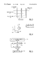
- FIG. 1 shows a prior art toaster 100 that is utilized for toasting a piece of bread.
- the toaster 100 utilizes a first heating element 110 , and a second heating element (not shown) that are in close proximity to each other.
- the heating elements typically are wrapped around or backed by a heat resistant object 120 , such as a mica sheet.
- the heating elements are connected to a power line 130 through a switch (not shown).
- a piece of bread is placed between the heating elements and the switch is closed for a period of time (t) until the bread is browned to a desired level.
- the surface of the bread after browning typically has a uniform monotonic browning pattern.
- An oven utilizes a similar arrangement of one or two heating elements to uniformly brown or dry objects placed therein such as food objects, pottery objects, industrial objects, etc.
- Japanese Patent No. 3,258,226 to Masaru shows a system wherein a changeable mold is utilized as the resistant object.
- a computer is connected to the toaster.
- the mold is transformed into the shape of characters shown on the computer display.
- the mold is then brought into contact with the surface of the bread and the toaster is then switched on.
- the portion of the bread surface in contact with the mold is not toasted and the other portions of the bread surface are toasted.
- desired characters may be freely drawn or patterns formed on a slice of bread.
- This system is very complex in that a changeable mold is required to form the desired patterns on the bread surface. This has the effect of raising the price and complexity of the toaster.
- Japanese Patent No. 2,279,118 to Toshihiko shows a different type of toaster wherein a heater nozzle is utilized for drawing a pattern onto the surface of the bread.
- the heater nozzle is moved over the surface of the bread while air is blown through the heater nozzle.
- the air is heated by the heater nozzle and blown at the surface of the bread thereby producing a browning of the surface of the bread.
- the heater nozzle is controlled by a stepper motor connected to a control circuit for the purposes of moving the heater nozzle over the surface of the bread thereby forming a desired pattern on the surface of the bread.
- This toaster is again overly complex and expensive to implement and has the added drawback of overly drying the bread as the pattern is drawn.
- a still yet further object of the present invention is to produce a heating apparatus wherein the shape/size of the heating pattern is controllable.
- a heating apparatus having a heating grid array wherein individual elements of the heating grid array may be selected, thereby producing a heating/browning effect from the selected elements.
- groups of the individual elements may be selected such that a desired heating/browning pattern is achieved.
- the heat is applied to an object by first bringing the object into close proximity with the grid array. Thereafter, elements of the grid array may be selected for a duration of time such that a desired heating/browning pattern is produced.
- the heating apparatus may contain an addressing circuit for addressing the grid array and a memory for storing heating/browning patterns.
- the heating device may also contain a timing element for controlling the duration of time that the heating/browning pattern is applied to the object.
- the memory may in this case contain duration data corresponding to all, or portions of the selected elements of the grid array. The duration data may vary over the selected elements of the grid array so that different selected elements are selected for different durations of time.
- FIG. 1 shows a prior art toaster that is utilized for toasting a piece of bread
- FIG. 2 depicts an illustrative heating/browning device in accordance with an embodiment of the present invention
- FIG. 2A shows mechanical components of an embodiment in accordance with the present invention wherein a pair of heating/browning arrays are vertically positioned;
- FIG. 3 shows a detailed view of a heating/browning array configured as a bread array
- FIG. 4 is a block diagram illustrating the operation of a particular pixel of a heating/browning array in accordance with an embodiment of the present invention.
- FIG. 5 is a flow diagram illustrating the operation of an embodiment of a heating/browning device in accordance with the present invention, such as for example shown in FIG. 2 .
- FIG. 2 depicts an illustrative heating/browning device 200 in accordance with an embodiment of the present invention.
- the heating/browning device 200 has a heating/browning array 210 , an addressing circuit 220 , a memory 230 , and a control device 240 .
- the memory 230 is illustratively shown as a separate device from the addressing circuit 220 . However, as a person of ordinary skill in the art would appreciate, the memory 230 could readily be integrated into the addressing circuit 220 , the control device 240 , or any other suitable component.
- the heating/browning array 210 receives selector lines 212 (e.g., x-column selector lines) and selector lines 214 (e.g., y-row selector lines) from the addressing circuit 220 .
- the selector lines are utilized for selecting (e.g., turning on) elements of the heating/browning array 210 as discussed in more detail herein below.
- the addressing circuit receives a control input signal 224 for selecting a desired heating/browning pattern from the control device 240 .
- the control device 240 may be a simple selector knob that selects from predefined heating/browning patterns.
- the control device 240 may be a hardware circuit, a programmable circuit, a software device, or some combination thereof, such as a personal computing device running an operating system and an application program.
- the addressing circuit 220 also receives data from a memory 230 over a data input 234 .
- the data corresponds to heating/browning array address and timing information for selecting corresponding elements of the heating/browning array 210 and thereby, producing the predefined heating/browning patterns.
- the timing information is utilized by a timing control element 222 for controlling the duration of turn on time for each element of the heating/browning array 210 .
- the timing information may be the same for each element of the heating/browning array 210 . In this case, a uniform heating/browning pattern is produced by each of the on elements of the heating/browning array 210 .
- the data for the memory 230 may not contain timing information or there may be timing information that corresponds to all the selected elements.
- the timing control element 222 may correspond to a mechanical device, a hardware timing device, a software timing device, etc.
- the timing control element 222 may be a mechanical timer wherein the duration is selectable via a rotary or slidable selector knob. In other embodiments, the duration may be fixed for all heating/browning patterns.
- the timing information may be unique for portions of elements, or even individual elements of the heating/browning array 210 .
- a varied heating/browning pattern may be produced across the heating/browning array 210 .
- varying shades of browning patterns may be produced by varying the heating duration for the elements of the heating/browning array 210 .
- the heating/browning array 210 may be utilized for selectively drying portions of an applied film, such as an epoxy coating, a masking layer, a conductive layer, a dielectric layer, etc., without applying excessive heat to heat sensitive portions of an underlying integrated circuit (IC) chip.
- an applied film such as an epoxy coating, a masking layer, a conductive layer, a dielectric layer, etc.
- the heating/browning array 210 may produce a power saving in applications wherein the heating/browning array 210 is larger than an object placed in close proximity for the purposes of applying the heating/browning pattern. In this case, only the portion of the heating/browning array 210 in proximity with the object need be selected (e.g., turned on), while portions of the heating/browning array 210 not in proximity with the object need not be selected. In this way, a general multipurpose heating device is operable for applying a heating/browning pattern to a multitude of differently sized and shaped objects, in an energy efficient manner.
- the heating/browning array 210 may be desirable to have the heating/browning array 210 moved to a closer proximity to the object after the object is positioned. For instance, in the case of a toaster, in may be desirable to have the heating/browning array 210 moved closer to a food object, such as a slice of bread, after the bread is inserted into the toaster. In this way, the toaster may be adapted to readily accept various widths of bread slices. In addition, the heating/browning array 210 may produce a more distinctive pattern on the bread when it is in closer proximity to the bread.
- any known system for repositioning an object may be readily adapted for also repositioning one or more of the heating/browning arrays.
- a pair of centering control plates that ensure that the object is properly centered between a pair of heating/browning arrays may also be utilized for repositioning the heating/browning arrays.
- FIG. 2A shows mechanical components of an embodiment wherein a pair of heating/browning arrays 210 are vertically positioned, such as for a toaster 295 .
- the pair of heating/browning arrays 210 respectively have pins 251 , 253 , and 252 , 254 for fixing the pair of heating/browning arrays 210 in a horizontal plane within horizontal tracks 250 and enabling repositioning within the horizontal plane as described herein below.
- the pins 253 , 254 also act to rotatably affix the pair of heating/browning arrays 210 to respective connecting members 263 , 265 .
- the connecting members 263 , 265 are in turn rotatably attached to a horizontal member 264 via pins 262 , 261 .
- the pins 262 , 261 are positioned within vertical tracks 260 and thereby, affix the horizontal member 264 in a horizontal position, yet allow motion in a vertical plane within the vertical tracks 260 .
- the horizontal member 264 is fixedly attached to a lower end of a shaft 290 .
- An upper end of the shaft 290 is connected to a knob 270 and an upper end of a spring member 280 .
- a lower end of the spring member 280 is fixedly attached to one of the horizontal tracks 250 .
- the toaster 295 is shown in an initial position.
- an object may be positioned between the pair of heating/browning arrays 210 .
- the knob 270 may be repositioned in a downward direction, thereby compressing the spring member 280 between the knob 270 and the horizontal track 250 .
- the shaft 290 in turn moves the horizontal member 264 in a downward position. Since the pins 262 , 261 are fixed by vertical tracks 260 , and the pins 253 , 254 are fixed by the lower horizontal track 250 , the downward movement of the horizontal member 264 rotates the members 263 , 265 up and inward as indicated by repositioning arrows 296 . The rotating of the members 263 and 265 shifts the pair of heating/browning arrays inwards.
- the pair of heating/browning arrays are selectably turned on as described in more detail herein.
- the pair of heating/browning arrays 210 are turned off and the spring 280 acts to return the above components of the toaster 295 to the initial position.
- FIG. 3 shows a detailed view of a heating/browning array configured as a bread array 310 .
- the bread array 310 has selector lines 312 and selector lines 314 for selecting bread pixels 311 of the bread array 310 .
- a particular combination of selector lines is operable for selecting a corresponding one of the bread pixels 311 .
- any combination of on and off bread pixels may be selected for producing a desired browning pattern on the surface of the slice of bread.
- the addressing circuit 220 shown in FIG. 2 is operable to individually address any combination of on bread pixels for producing a desired heating/browning pattern.
- the selector lines 312 may correspond to X-column selector lines and the selector lines 314 may correspond to Y-row selector lines.
- the selector lines are operable for producing one or more rectangular heating/browning patterns.
- each one of the X-column selector lines and the Y-row selector lines address a corresponding column or row of the heating/browning array. In operation, any pixel that is positioned on a selected “on” X-column and Y-row will be “on”. Any pixel that is positioned on an X-column and/or Y-row that is “off”, will also be “off”.
- FIG. 4 is a block diagram illustrating the operation of a particular pixel 411 of a heating/browning array.
- the pixel 411 receives a power input 416 , an X-selector line 412 , and a Y-selector line 414 .
- the pixel 411 is on. If one or both of the X-selector line 412 and the Y-selector line 414 are off, the pixel 411 is off.
- FIG. 5 is a flow diagram illustrating the operation of an embodiment of the heating/browning device 200 shown in FIG. 2 .
- the control device 240 controls the addressing circuit 220 through control input 224 to retrieve picture content (e.g., a pattern) from the memory 230 .
- the picture content corresponds to a particular combination and “on” duration of pixel elements and may be expressed as:
- x one of on or off for each pixel element x ij ,y ij ;
- t heating duration for each pixel element x ij ,y ij .
- the “on” duration for an element that is not desirably selected for a given pattern may be zero. In this way, each element of the heating/browning array may be configured for each pattern.
- the addressing circuit 220 addresses the heating/browning array 210 to turn on selected pixel elements corresponding to the selected picture content and starts the timing control element 222 for timing the on duration of the selected pixel elements.
- the timing control element 222 determines if the on duration of each of the selected pixel elements, a portion of the selected pixel elements, or all of the selected pixel elements has expired. For the selected pixels wherein the on duration has expired, in step 540 the pixels are turned off. For the selected pixels wherein the on duration has not yet expired, the pixels are maintained on until the on duration has expired.
- the memory 230 may receive patterns, such as picture patterns, from a pattern input 232 .
- the pattern input 232 may correspond to a power line wherein pattern data is embedded within a carrier wave.
- the pattern input 232 may be connected to an internet service provider (ISP) 242 and patterns may be downloaded from the Internet or the ISP 242 directly.
- ISP internet service provider
- the pattern input 232 may receive a signal during the vertical blanking interval of a television broadcast signal.
- the control device 240 may correspond to a personal computing device (PC) and the picture patterns may be received from the PC and/or may be created on the PC utilizing a general or specially configured pattern creation program.
- PC personal computing device
- a program may be utilized to capture printer output signals from the control device 240 via the pattern input 232 and interpret the printer output signals as picture patterns.
- the pattern input 232 may be connected to a flash memory slot or an other connector for receiving additional memory devices. In this way, a user may acquire (e.g., buy, rent, etc.) additional images for use with device of the present invention.
Abstract
A heating apparatus having a heating grid array wherein individual elements of the heating grid array may by selected, thereby producing a heating/browning effect from the selected elements. Groups of the individual elements may be selected such that a desired heating/browning pattern is achieved. Elements of the grid array are selected for a duration of time such that a desired heating/browning pattern is produced. The heating apparatus contains an addressing circuit for addressing the grid array and a memory for storing heating/browning patterns. The heating device also contains a timing element for controlling the duration of time that the heating/browning pattern is applied. The memory contains duration data corresponding to all, or portions of the selected elements of the grid array. The duration data varies over the selected elements of the grid array so that different selected elements of the grid array are selected for different durations of time.
Description
This invention generally relates to an apparatus for applying a heating/browning pattern to an object such as a food product. Specifically, the present invention pertains to utilizing a selectable heating element to apply a heating/browning pattern.
Devices are known that have the ability to brown an object by applying heat through the use of a heating element such as a resistive metal strip. FIG. 1 shows a prior art toaster 100 that is utilized for toasting a piece of bread. As shown, the toaster 100 utilizes a first heating element 110, and a second heating element (not shown) that are in close proximity to each other. The heating elements typically are wrapped around or backed by a heat resistant object 120, such as a mica sheet. The heating elements are connected to a power line 130 through a switch (not shown). In operation, a piece of bread is placed between the heating elements and the switch is closed for a period of time (t) until the bread is browned to a desired level. The surface of the bread after browning typically has a uniform monotonic browning pattern. An oven utilizes a similar arrangement of one or two heating elements to uniformly brown or dry objects placed therein such as food objects, pottery objects, industrial objects, etc.
In the prior art, it is also known that placing a heat resistant object between the heating element and the object to be browned, such as a slice of bread, may produce a non-uniform pattern of browning. Such systems are described in U.S. Pat. No. 1,892,117 to Perkins, U.S. Pat. No. 4,656,927 to Mosby, and U.S. Pat. No. 5,156,637 to Wai-Ching. The problem with these prior art toasters is that differently shaped heat resistant objects are required for producing each different heating pattern in the bread.
Japanese Patent No. 3,258,226 to Masaru shows a system wherein a changeable mold is utilized as the resistant object. In this system, a computer is connected to the toaster. The mold is transformed into the shape of characters shown on the computer display. The mold is then brought into contact with the surface of the bread and the toaster is then switched on. The portion of the bread surface in contact with the mold is not toasted and the other portions of the bread surface are toasted. In this way, desired characters may be freely drawn or patterns formed on a slice of bread. This system is very complex in that a changeable mold is required to form the desired patterns on the bread surface. This has the effect of raising the price and complexity of the toaster.
Japanese Patent No. 2,279,118 to Toshihiko shows a different type of toaster wherein a heater nozzle is utilized for drawing a pattern onto the surface of the bread. In operation, the heater nozzle is moved over the surface of the bread while air is blown through the heater nozzle. The air is heated by the heater nozzle and blown at the surface of the bread thereby producing a browning of the surface of the bread. The heater nozzle is controlled by a stepper motor connected to a control circuit for the purposes of moving the heater nozzle over the surface of the bread thereby forming a desired pattern on the surface of the bread. This toaster is again overly complex and expensive to implement and has the added drawback of overly drying the bread as the pattern is drawn.
Accordingly, it is an object of the present invention to overcome the disadvantages of the prior art.
It is a further object of the present invention to provide an apparatus wherein a desired pattern may be readily browned into the surface of an object in a simple and inexpensive way.
It is still a further object of the present invention to provide an apparatus that may form a desired browning pattern without the need of utilizing changeable heat resistant shields.
A still yet further object of the present invention is to produce a heating apparatus wherein the shape/size of the heating pattern is controllable.
These and other objects of the present invention are achieved by a heating apparatus having a heating grid array wherein individual elements of the heating grid array may be selected, thereby producing a heating/browning effect from the selected elements. In operation, groups of the individual elements may be selected such that a desired heating/browning pattern is achieved. The heat is applied to an object by first bringing the object into close proximity with the grid array. Thereafter, elements of the grid array may be selected for a duration of time such that a desired heating/browning pattern is produced. The heating apparatus may contain an addressing circuit for addressing the grid array and a memory for storing heating/browning patterns. The heating device may also contain a timing element for controlling the duration of time that the heating/browning pattern is applied to the object. The memory may in this case contain duration data corresponding to all, or portions of the selected elements of the grid array. The duration data may vary over the selected elements of the grid array so that different selected elements are selected for different durations of time.
The following are descriptions of embodiments of the present invention that when taken in conjunction with the following drawings will demonstrate the above noted features and advantages, as well as further ones. It should be expressly understood that the drawings are included for illustrative purposes and do not represent the scope of a present invention. The invention is best understood in conjunction with the accompanying drawings in which:
FIG. 1 shows a prior art toaster that is utilized for toasting a piece of bread;
FIG. 2 depicts an illustrative heating/browning device in accordance with an embodiment of the present invention;
FIG. 2A shows mechanical components of an embodiment in accordance with the present invention wherein a pair of heating/browning arrays are vertically positioned;
FIG. 3 shows a detailed view of a heating/browning array configured as a bread array;
FIG. 4 is a block diagram illustrating the operation of a particular pixel of a heating/browning array in accordance with an embodiment of the present invention; and
FIG. 5 is a flow diagram illustrating the operation of an embodiment of a heating/browning device in accordance with the present invention, such as for example shown in FIG. 2.
FIG. 2 depicts an illustrative heating/browning device 200 in accordance with an embodiment of the present invention. The heating/browning device 200 has a heating/browning array 210, an addressing circuit 220, a memory 230, and a control device 240. The memory 230 is illustratively shown as a separate device from the addressing circuit 220. However, as a person of ordinary skill in the art would appreciate, the memory 230 could readily be integrated into the addressing circuit 220, the control device 240, or any other suitable component.
The heating/browning array 210 receives selector lines 212 (e.g., x-column selector lines) and selector lines 214 (e.g., y-row selector lines) from the addressing circuit 220. The selector lines are utilized for selecting (e.g., turning on) elements of the heating/browning array 210 as discussed in more detail herein below. The addressing circuit receives a control input signal 224 for selecting a desired heating/browning pattern from the control device 240. In one embodiment, the control device 240 may be a simple selector knob that selects from predefined heating/browning patterns. In an alternate embodiment, the control device 240 may be a hardware circuit, a programmable circuit, a software device, or some combination thereof, such as a personal computing device running an operating system and an application program.
The addressing circuit 220 also receives data from a memory 230 over a data input 234. The data corresponds to heating/browning array address and timing information for selecting corresponding elements of the heating/browning array 210 and thereby, producing the predefined heating/browning patterns. The timing information is utilized by a timing control element 222 for controlling the duration of turn on time for each element of the heating/browning array 210. For some heating/browning patterns, the timing information may be the same for each element of the heating/browning array 210. In this case, a uniform heating/browning pattern is produced by each of the on elements of the heating/browning array 210.
For embodiments wherein a uniform heating/browning pattern is desired over the selected elements of the heating/browning array 210, the data for the memory 230 may not contain timing information or there may be timing information that corresponds to all the selected elements. In these embodiments, the timing control element 222 may correspond to a mechanical device, a hardware timing device, a software timing device, etc. In the case of a mechanical device, the timing control element 222 may be a mechanical timer wherein the duration is selectable via a rotary or slidable selector knob. In other embodiments, the duration may be fixed for all heating/browning patterns.
For some heating/browning patterns, the timing information may be unique for portions of elements, or even individual elements of the heating/browning array 210. By varying the timing information for the elements of the heating/browning array 210, a varied heating/browning pattern may be produced across the heating/browning array 210. In this way, for example, when the heating/browning array 210 is utilized as a heating element for toaster, varying shades of browning patterns may be produced by varying the heating duration for the elements of the heating/browning array 210. In industrial applications, the heating/browning array 210 may be utilized for selectively drying portions of an applied film, such as an epoxy coating, a masking layer, a conductive layer, a dielectric layer, etc., without applying excessive heat to heat sensitive portions of an underlying integrated circuit (IC) chip.
In addition, the heating/browning array 210 may produce a power saving in applications wherein the heating/browning array 210 is larger than an object placed in close proximity for the purposes of applying the heating/browning pattern. In this case, only the portion of the heating/browning array 210 in proximity with the object need be selected (e.g., turned on), while portions of the heating/browning array 210 not in proximity with the object need not be selected. In this way, a general multipurpose heating device is operable for applying a heating/browning pattern to a multitude of differently sized and shaped objects, in an energy efficient manner.
In some embodiments, it may be desirable to have the heating/browning array 210 moved to a closer proximity to the object after the object is positioned. For instance, in the case of a toaster, in may be desirable to have the heating/browning array 210 moved closer to a food object, such as a slice of bread, after the bread is inserted into the toaster. In this way, the toaster may be adapted to readily accept various widths of bread slices. In addition, the heating/browning array 210 may produce a more distinctive pattern on the bread when it is in closer proximity to the bread. As a person of ordinary skill in the art would readily appreciate, any known system for repositioning an object may be readily adapted for also repositioning one or more of the heating/browning arrays. For instance, a pair of centering control plates that ensure that the object is properly centered between a pair of heating/browning arrays may also be utilized for repositioning the heating/browning arrays.
FIG. 2A shows mechanical components of an embodiment wherein a pair of heating/browning arrays 210 are vertically positioned, such as for a toaster 295. The pair of heating/browning arrays 210 respectively have pins 251, 253, and 252, 254 for fixing the pair of heating/browning arrays 210 in a horizontal plane within horizontal tracks 250 and enabling repositioning within the horizontal plane as described herein below. The pins 253, 254 also act to rotatably affix the pair of heating/browning arrays 210 to respective connecting members 263, 265. The connecting members 263, 265 are in turn rotatably attached to a horizontal member 264 via pins 262, 261. The pins 262, 261 are positioned within vertical tracks 260 and thereby, affix the horizontal member 264 in a horizontal position, yet allow motion in a vertical plane within the vertical tracks 260. The horizontal member 264 is fixedly attached to a lower end of a shaft 290. An upper end of the shaft 290 is connected to a knob 270 and an upper end of a spring member 280. A lower end of the spring member 280 is fixedly attached to one of the horizontal tracks 250. In FIG. 2A, the toaster 295 is shown in an initial position.
In this embodiment, an object may be positioned between the pair of heating/browning arrays 210. Thereafter, the knob 270 may be repositioned in a downward direction, thereby compressing the spring member 280 between the knob 270 and the horizontal track 250. The shaft 290 in turn moves the horizontal member 264 in a downward position. Since the pins 262, 261 are fixed by vertical tracks 260, and the pins 253, 254 are fixed by the lower horizontal track 250, the downward movement of the horizontal member 264 rotates the members 263, 265 up and inward as indicated by repositioning arrows 296. The rotating of the members 263 and 265 shifts the pair of heating/browning arrays inwards. At this time, the pair of heating/browning arrays are selectably turned on as described in more detail herein. At the end of a given duration, the pair of heating/browning arrays 210 are turned off and the spring 280 acts to return the above components of the toaster 295 to the initial position.
FIG. 3 shows a detailed view of a heating/browning array configured as a bread array 310. As shown, the bread array 310 has selector lines 312 and selector lines 314 for selecting bread pixels 311 of the bread array 310. In one embodiment, a particular combination of selector lines is operable for selecting a corresponding one of the bread pixels 311. In this way, any combination of on and off bread pixels may be selected for producing a desired browning pattern on the surface of the slice of bread. In this embodiment, the addressing circuit 220 shown in FIG. 2 is operable to individually address any combination of on bread pixels for producing a desired heating/browning pattern.
In an alternate embodiment, the selector lines 312 may correspond to X-column selector lines and the selector lines 314 may correspond to Y-row selector lines. In this embodiment, the selector lines are operable for producing one or more rectangular heating/browning patterns. In this embodiment, each one of the X-column selector lines and the Y-row selector lines address a corresponding column or row of the heating/browning array. In operation, any pixel that is positioned on a selected “on” X-column and Y-row will be “on”. Any pixel that is positioned on an X-column and/or Y-row that is “off”, will also be “off”.
FIG. 4 is a block diagram illustrating the operation of a particular pixel 411 of a heating/browning array. As shown, the pixel 411 receives a power input 416, an X-selector line 412, and a Y-selector line 414. In operation, if the X-selector line 412 and the Y-selector line 414 are on, then the pixel 411 is on. If one or both of the X-selector line 412 and the Y-selector line 414 are off, the pixel 411 is off.
FIG. 5 is a flow diagram illustrating the operation of an embodiment of the heating/browning device 200 shown in FIG. 2. In step 510, the control device 240 controls the addressing circuit 220 through control input 224 to retrieve picture content (e.g., a pattern) from the memory 230. The picture content corresponds to a particular combination and “on” duration of pixel elements and may be expressed as:
{x,y,t}|(xij,yij): Picture Content, wherein
x=one of on or off for each pixel element xij,yij;
y=one of on or off for each pixel element xij,yij; and
t=heating duration for each pixel element xij,yij.
It should be noted that the “on” duration for an element that is not desirably selected for a given pattern, may be zero. In this way, each element of the heating/browning array may be configured for each pattern.
In step 520, the addressing circuit 220 addresses the heating/browning array 210 to turn on selected pixel elements corresponding to the selected picture content and starts the timing control element 222 for timing the on duration of the selected pixel elements. In step 530, the timing control element 222 determines if the on duration of each of the selected pixel elements, a portion of the selected pixel elements, or all of the selected pixel elements has expired. For the selected pixels wherein the on duration has expired, in step 540 the pixels are turned off. For the selected pixels wherein the on duration has not yet expired, the pixels are maintained on until the on duration has expired.
As shown in FIG. 2, the memory 230 may receive patterns, such as picture patterns, from a pattern input 232. In one embodiment, the pattern input 232 may correspond to a power line wherein pattern data is embedded within a carrier wave. In another embodiment, the pattern input 232 may be connected to an internet service provider (ISP) 242 and patterns may be downloaded from the Internet or the ISP 242 directly. In other embodiments the pattern input 232 may receive a signal during the vertical blanking interval of a television broadcast signal. In yet another embodiment, the control device 240 may correspond to a personal computing device (PC) and the picture patterns may be received from the PC and/or may be created on the PC utilizing a general or specially configured pattern creation program. In this embodiment or yet still a further embodiment, a program may be utilized to capture printer output signals from the control device 240 via the pattern input 232 and interpret the printer output signals as picture patterns. The pattern input 232 may be connected to a flash memory slot or an other connector for receiving additional memory devices. In this way, a user may acquire (e.g., buy, rent, etc.) additional images for use with device of the present invention.
Finally, the above-discussion is intended to be merely illustrative of the invention. Numerous alternative embodiments may be devised by those having ordinary skill in the art without departing from the spirit and scope of the following claims.
Claims (18)
1. A method of selectively applying heat to an object comprising:
receiving a heating pattern from an Internet Service Provider (ISP);
applying said heating pattern to the object utilizing an addressable heating array, wherein said heating pattern selectively turns on a portion of said addressable heating array.
2. The method of claim 1, wherein said heating pattern includes duration data, said method comprising applying said heating pattern in accordance with said duration data.
3. The method of claim 2, wherein said duration data varies over said portion of said heating array such that different parts of said portion of said heating array are on for different durations of time.
4. The method of claim 1, wherein said ISP comprises a plurality of heating patterns, said method comprising selecting a particular one of said plurality of heating patterns for receiving by said addressing device.
5. The method of claim 1, further comprising repositioning said addressable heating array closer to said object prior to applying said heating pattern.
6. A heating device for applying heat to an object, said device comprising:
an addressing device;
an addressable heating array configured to receive an output from said addressing device and to selectively turn on a portion of said, addressable heating array in accordance with said output; and
a pattern input, wherein said pattern input is configured to receive pattern data from said pattern input, and to produce said output in accordance with said pattern data, and wherein said pattern input is connected to an internet service provider (ISP).
7. The heating device of claim 6, wherein said output comprises duration data and said addressable heating array is configured to selectively turn on said portion of said addressable heating array in accordance with said duration data.
8. The heating device of claim 7, comprising a timing element, wherein said timing element is configured to turn on said portion of said addressable heating array at a start time and to turn off said portion of said addressable heating array at the end of said duration.
9. The heating device of claim 7, comprising a timing element, wherein said duration data varies over said portion of said addressable heating array, and wherein said timing element is configured to turn on and off said portion of said addressable heating array in accordance with said varied duration data.
10. The heating device of claim 6, comprising a memory operably coupled to said pattern input, wherein said addressing device is configured to receive said pattern data from said memory.
11. The heating device of claim 10, comprising a control device, wherein said memory is configured to contain a plurality of pattern data and said control device is configured to select one of said plurality of pattern data for receipt by said addressing device.
12. The heating device of claim 6, wherein said addressing device is configured to be connected to a computer and said addressing device is configured to receive pattern data from the computer and to produce said output in accordance with said pattern data.
13. The heating device of claim 12, wherein said addressing device is configured to be connected to a printer output of the computer and to convert a signal received from the printer output into said output from said addressing device.
14. A heating device for applying heat to an object, said device comprising:
an addressing device configured to be connected to a printer output of a computer; and
an addressable heating array configured to receive an output from said addressing device and to selectively turn on a portion of said addressable heating array in accordance with said output, wherein said addressing device is configured to convert a signal received from the printer output into said output from said addressing device.
15. The heating device of claim 14, wherein said output comprises duration data and said addressable heating array is configured to selectively turn on said portion of said addressable heating array in accordance with said duration data.
16. The heating device of claim 15, comprising a timing element, wherein said timing element is configured to turn on said portion of said addressable heating array at a start time and to turn off said portion of said addressable heating array at the end of said duration.
17. The heating device of claim 15, wherein said duration data varies over said portion of said addressable heating array, and wherein said portion of said addressable heating array is configured to turn on and off in accordance with said varied duration data.
18. The heating device of claim 15, comprising a timing element, wherein said duration data varies over said portion of said addressable heating array, and wherein said timing element is configured to turn on and off said portion of said addressable heating array in accordance with said varied duration data.
Priority Applications (6)
| Application Number | Priority Date | Filing Date | Title |
|---|---|---|---|
| US09/352,097 US6323467B1 (en) | 1999-07-14 | 1999-07-14 | Method and apparatus for selectively applying heat to an object using an addressable array |
| PCT/EP2000/006370 WO2001005286A1 (en) | 1999-07-14 | 2000-07-05 | Method and apparatus for selectively applying heat to an object |
| EP00945885A EP1113746B1 (en) | 1999-07-14 | 2000-07-05 | Method and apparatus for selectively applying heat to an object |
| DE60007715T DE60007715T2 (en) | 1999-07-14 | 2000-07-05 | METHOD AND DEVICE FOR SELECTIVELY HEATING AN OBJECT |
| JP2001510352A JP2003504831A (en) | 1999-07-14 | 2000-07-05 | Method and apparatus for selectively applying heat to an object |
| CN00801404.3A CN1131694C (en) | 1999-07-14 | 2000-07-05 | Method and appts. for selectively applying heat to object |
Applications Claiming Priority (1)
| Application Number | Priority Date | Filing Date | Title |
|---|---|---|---|
| US09/352,097 US6323467B1 (en) | 1999-07-14 | 1999-07-14 | Method and apparatus for selectively applying heat to an object using an addressable array |
Publications (1)
| Publication Number | Publication Date |
|---|---|
| US6323467B1 true US6323467B1 (en) | 2001-11-27 |
Family
ID=23383785
Family Applications (1)
| Application Number | Title | Priority Date | Filing Date |
|---|---|---|---|
| US09/352,097 Expired - Fee Related US6323467B1 (en) | 1999-07-14 | 1999-07-14 | Method and apparatus for selectively applying heat to an object using an addressable array |
Country Status (6)
| Country | Link |
|---|---|
| US (1) | US6323467B1 (en) |
| EP (1) | EP1113746B1 (en) |
| JP (1) | JP2003504831A (en) |
| CN (1) | CN1131694C (en) |
| DE (1) | DE60007715T2 (en) |
| WO (1) | WO2001005286A1 (en) |
Cited By (13)
| Publication number | Priority date | Publication date | Assignee | Title |
|---|---|---|---|---|
| US20050002659A1 (en) * | 2001-10-09 | 2005-01-06 | Stylianos Panaghe | Radiant electric heating element |
| US20060251784A1 (en) * | 2005-05-03 | 2006-11-09 | Sells Joel M | Method for cooking meat using steam |
| US20060251785A1 (en) * | 2005-05-06 | 2006-11-09 | Stefania Fraccon | Method for cooking food using steam |
| US20070104844A1 (en) * | 2005-07-11 | 2007-05-10 | Stefania Fraccon | Method for baking bread using steam |
| GB2433693A (en) * | 2005-12-29 | 2007-07-04 | Matthew Nutley | A device for toasting a design onto bread |
| US20090136640A1 (en) * | 2007-11-26 | 2009-05-28 | Whirlpool Corporation | Method for Baking a Casserole Using Steam |
| US7867534B2 (en) | 2006-10-18 | 2011-01-11 | Whirlpool Corporation | Cooking appliance with steam generator |
| CN101940440A (en) * | 2010-07-29 | 2011-01-12 | 浙江大学 | Raster graphic heating device and toaster using same |
| US8207477B2 (en) | 2007-11-26 | 2012-06-26 | Whirlpool Corporation | Method for cooking vegetables using steam |
| WO2014179270A1 (en) * | 2013-04-29 | 2014-11-06 | Zeta Function LLC | System and method for generation of food items with visible indicia |
| US20160249647A1 (en) * | 2013-07-03 | 2016-09-01 | Mecanique Systemes | Process for laser etching a pattern on a sandwich roll or bun |
| US10430620B2 (en) | 2018-02-26 | 2019-10-01 | International Business Machines Corporation | Dynamic thermoelectric image branding |
| US10586138B2 (en) | 2017-11-02 | 2020-03-10 | International Business Machines Corporation | Dynamic thermoelectric quick response code branding |
Families Citing this family (3)
| Publication number | Priority date | Publication date | Assignee | Title |
|---|---|---|---|---|
| CN104983320A (en) * | 2015-08-02 | 2015-10-21 | 邹思佳 | Bread machine |
| TWI560534B (en) * | 2015-11-05 | 2016-12-01 | Leadot Innovation Inc | Programmable graphic radiation generator and programmable graphically radiating method |
| CN106963249A (en) * | 2017-03-28 | 2017-07-21 | 王金锁 | A kind of picture bread producing machine processed |
Citations (25)
| Publication number | Priority date | Publication date | Assignee | Title |
|---|---|---|---|---|
| US1332935A (en) * | 1919-07-11 | 1920-03-09 | Mary A Thomas | Electric toaster |
| US1892117A (en) | 1930-11-11 | 1932-12-27 | George B Perkins | Cooking device |
| US2383673A (en) * | 1942-02-21 | 1945-08-28 | Mcgraw Electric Co | Electric toaster |
| US2849946A (en) * | 1957-02-05 | 1958-09-02 | Westinghouse Electric Corp | Toaster apparatus |
| US2910929A (en) * | 1957-01-03 | 1959-11-03 | Westinghouse Electric Corp | Toaster apparatus |
| US3641921A (en) * | 1969-11-14 | 1972-02-15 | Matsushita Electric Ind Co Ltd | Electric toaster |
| US3781515A (en) * | 1969-08-08 | 1973-12-25 | Texas Instruments Inc | Integrated heater element array and drive matrix |
| US4038516A (en) * | 1975-02-19 | 1977-07-26 | Facit Aktiebolag | Thermal printing head |
| US4287521A (en) * | 1979-03-24 | 1981-09-01 | Hitachi, Ltd. | CRT Hard copy apparatus with multi-directional sampling and printing |
| US4524386A (en) * | 1982-04-12 | 1985-06-18 | The United States Of America As Represented By The Secretary Of The Army | Thermal target display system |
| US4656927A (en) | 1985-12-09 | 1987-04-14 | Mosby Bob L | Device for making designs on toast |
| US4754120A (en) * | 1984-08-24 | 1988-06-28 | Hitachi, Ltd. | Method of regulating the temperature of a body to be heated |
| US4775775A (en) * | 1987-06-16 | 1988-10-04 | Srtechnologies, Inc. | Programmable electrical heater |
| JPH0210601A (en) * | 1988-06-28 | 1990-01-16 | Nec Corp | Infrared pseudo light source device |
| JPH0210602A (en) * | 1988-06-28 | 1990-01-16 | Nec Corp | Infrared pseudo light source device |
| JPH02279118A (en) | 1989-04-20 | 1990-11-15 | Matsushita Electric Ind Co Ltd | Toaster |
| US4988032A (en) * | 1985-11-29 | 1991-01-29 | Kawasaki Jukogyo Kabushiki Kaisha | Method for assembling a structural panel in order to prevent the sag thereof |
| JPH03258226A (en) | 1990-03-09 | 1991-11-18 | Matsushita Electric Ind Co Ltd | Toaster |
| US5156637A (en) | 1991-03-04 | 1992-10-20 | Wai Ching Yick | Toaster |
| US5590238A (en) * | 1990-03-05 | 1996-12-31 | Birger Ericson Fasad Ab | Horizontally and vertically movable radiant heater for removing paint from a surface |
| US5653158A (en) * | 1993-12-21 | 1997-08-05 | Seb S.A. | Electrical food toasting or heating appliance, particularly a toaster, having two toasting sub-assemblies moved by control arms |
| US5659657A (en) * | 1995-05-24 | 1997-08-19 | Brokaw, Inc. | Pivotally mounted radiant heating apparatus with adjustable heaters |
| US5819637A (en) * | 1996-04-29 | 1998-10-13 | U.S. Philips Corporation | Toaster having heating elements whose heating area depends on the slice size |
| JPH1187256A (en) * | 1997-09-05 | 1999-03-30 | Tokyo Electron Ltd | Vacuum treatment apparatus |
| US6072154A (en) * | 1996-09-05 | 2000-06-06 | Medtronic, Inc. | Selectively activated shape memory device |
Family Cites Families (2)
| Publication number | Priority date | Publication date | Assignee | Title |
|---|---|---|---|---|
| US2483669A (en) * | 1945-12-15 | 1949-10-04 | Reid Andrew Marshall | Toast-marking electric heating assembly |
| JPH06217889A (en) * | 1993-01-27 | 1994-08-09 | Sakio Mitomi | Electric toaster |
-
1999
- 1999-07-14 US US09/352,097 patent/US6323467B1/en not_active Expired - Fee Related
-
2000
- 2000-07-05 DE DE60007715T patent/DE60007715T2/en not_active Expired - Fee Related
- 2000-07-05 EP EP00945885A patent/EP1113746B1/en not_active Expired - Lifetime
- 2000-07-05 JP JP2001510352A patent/JP2003504831A/en active Pending
- 2000-07-05 CN CN00801404.3A patent/CN1131694C/en not_active Expired - Fee Related
- 2000-07-05 WO PCT/EP2000/006370 patent/WO2001005286A1/en active IP Right Grant
Patent Citations (25)
| Publication number | Priority date | Publication date | Assignee | Title |
|---|---|---|---|---|
| US1332935A (en) * | 1919-07-11 | 1920-03-09 | Mary A Thomas | Electric toaster |
| US1892117A (en) | 1930-11-11 | 1932-12-27 | George B Perkins | Cooking device |
| US2383673A (en) * | 1942-02-21 | 1945-08-28 | Mcgraw Electric Co | Electric toaster |
| US2910929A (en) * | 1957-01-03 | 1959-11-03 | Westinghouse Electric Corp | Toaster apparatus |
| US2849946A (en) * | 1957-02-05 | 1958-09-02 | Westinghouse Electric Corp | Toaster apparatus |
| US3781515A (en) * | 1969-08-08 | 1973-12-25 | Texas Instruments Inc | Integrated heater element array and drive matrix |
| US3641921A (en) * | 1969-11-14 | 1972-02-15 | Matsushita Electric Ind Co Ltd | Electric toaster |
| US4038516A (en) * | 1975-02-19 | 1977-07-26 | Facit Aktiebolag | Thermal printing head |
| US4287521A (en) * | 1979-03-24 | 1981-09-01 | Hitachi, Ltd. | CRT Hard copy apparatus with multi-directional sampling and printing |
| US4524386A (en) * | 1982-04-12 | 1985-06-18 | The United States Of America As Represented By The Secretary Of The Army | Thermal target display system |
| US4754120A (en) * | 1984-08-24 | 1988-06-28 | Hitachi, Ltd. | Method of regulating the temperature of a body to be heated |
| US4988032A (en) * | 1985-11-29 | 1991-01-29 | Kawasaki Jukogyo Kabushiki Kaisha | Method for assembling a structural panel in order to prevent the sag thereof |
| US4656927A (en) | 1985-12-09 | 1987-04-14 | Mosby Bob L | Device for making designs on toast |
| US4775775A (en) * | 1987-06-16 | 1988-10-04 | Srtechnologies, Inc. | Programmable electrical heater |
| JPH0210602A (en) * | 1988-06-28 | 1990-01-16 | Nec Corp | Infrared pseudo light source device |
| JPH0210601A (en) * | 1988-06-28 | 1990-01-16 | Nec Corp | Infrared pseudo light source device |
| JPH02279118A (en) | 1989-04-20 | 1990-11-15 | Matsushita Electric Ind Co Ltd | Toaster |
| US5590238A (en) * | 1990-03-05 | 1996-12-31 | Birger Ericson Fasad Ab | Horizontally and vertically movable radiant heater for removing paint from a surface |
| JPH03258226A (en) | 1990-03-09 | 1991-11-18 | Matsushita Electric Ind Co Ltd | Toaster |
| US5156637A (en) | 1991-03-04 | 1992-10-20 | Wai Ching Yick | Toaster |
| US5653158A (en) * | 1993-12-21 | 1997-08-05 | Seb S.A. | Electrical food toasting or heating appliance, particularly a toaster, having two toasting sub-assemblies moved by control arms |
| US5659657A (en) * | 1995-05-24 | 1997-08-19 | Brokaw, Inc. | Pivotally mounted radiant heating apparatus with adjustable heaters |
| US5819637A (en) * | 1996-04-29 | 1998-10-13 | U.S. Philips Corporation | Toaster having heating elements whose heating area depends on the slice size |
| US6072154A (en) * | 1996-09-05 | 2000-06-06 | Medtronic, Inc. | Selectively activated shape memory device |
| JPH1187256A (en) * | 1997-09-05 | 1999-03-30 | Tokyo Electron Ltd | Vacuum treatment apparatus |
Cited By (20)
| Publication number | Priority date | Publication date | Assignee | Title |
|---|---|---|---|---|
| US7764873B2 (en) * | 2001-10-09 | 2010-07-27 | Stylianos Panaghe | Radiant electricating element with printed heating and ceramic tracks |
| US20050002659A1 (en) * | 2001-10-09 | 2005-01-06 | Stylianos Panaghe | Radiant electric heating element |
| US20060251784A1 (en) * | 2005-05-03 | 2006-11-09 | Sells Joel M | Method for cooking meat using steam |
| US20060251785A1 (en) * | 2005-05-06 | 2006-11-09 | Stefania Fraccon | Method for cooking food using steam |
| US10123556B2 (en) | 2005-05-06 | 2018-11-13 | Whirlpool Corporation | Method for cooking food using steam |
| US7745763B2 (en) | 2005-07-11 | 2010-06-29 | Whirlpool Corporation | Method for baking bread using steam |
| US20070104844A1 (en) * | 2005-07-11 | 2007-05-10 | Stefania Fraccon | Method for baking bread using steam |
| GB2433693A (en) * | 2005-12-29 | 2007-07-04 | Matthew Nutley | A device for toasting a design onto bread |
| US8704138B2 (en) | 2006-10-18 | 2014-04-22 | Whirlpool Corporation | Cooking appliance with steam generator |
| US7867534B2 (en) | 2006-10-18 | 2011-01-11 | Whirlpool Corporation | Cooking appliance with steam generator |
| US20100178395A1 (en) * | 2007-11-26 | 2010-07-15 | Whirlpool Corporation | Method for baking a casserole using steam |
| US20090136640A1 (en) * | 2007-11-26 | 2009-05-28 | Whirlpool Corporation | Method for Baking a Casserole Using Steam |
| US8207477B2 (en) | 2007-11-26 | 2012-06-26 | Whirlpool Corporation | Method for cooking vegetables using steam |
| US8697166B2 (en) * | 2007-11-26 | 2014-04-15 | Whirlpool Corporation | Method for baking a casserole using steam |
| CN101940440A (en) * | 2010-07-29 | 2011-01-12 | 浙江大学 | Raster graphic heating device and toaster using same |
| CN101940440B (en) * | 2010-07-29 | 2013-03-13 | 浙江大学 | Raster graphic heating device and toaster using same |
| WO2014179270A1 (en) * | 2013-04-29 | 2014-11-06 | Zeta Function LLC | System and method for generation of food items with visible indicia |
| US20160249647A1 (en) * | 2013-07-03 | 2016-09-01 | Mecanique Systemes | Process for laser etching a pattern on a sandwich roll or bun |
| US10586138B2 (en) | 2017-11-02 | 2020-03-10 | International Business Machines Corporation | Dynamic thermoelectric quick response code branding |
| US10430620B2 (en) | 2018-02-26 | 2019-10-01 | International Business Machines Corporation | Dynamic thermoelectric image branding |
Also Published As
| Publication number | Publication date |
|---|---|
| DE60007715T2 (en) | 2004-10-14 |
| DE60007715D1 (en) | 2004-02-19 |
| JP2003504831A (en) | 2003-02-04 |
| EP1113746A1 (en) | 2001-07-11 |
| CN1317947A (en) | 2001-10-17 |
| CN1131694C (en) | 2003-12-24 |
| WO2001005286A1 (en) | 2001-01-25 |
| EP1113746B1 (en) | 2004-01-14 |
Similar Documents
| Publication | Publication Date | Title |
|---|---|---|
| US6323467B1 (en) | Method and apparatus for selectively applying heat to an object using an addressable array | |
| US20160278563A1 (en) | Autonomous cooking device to prepare food from a recipe file and method for creating recipe files | |
| US6321639B1 (en) | Machine for making ice cream cones and other food products such as pannini | |
| US7227104B2 (en) | Thermal conductivity mask for producing patterns | |
| CA2434624A1 (en) | Appliance and method for cooking food articles | |
| WO2014179270A1 (en) | System and method for generation of food items with visible indicia | |
| US6753510B2 (en) | Methods and systems for quickly heating items | |
| US20060162573A1 (en) | Electric toaster | |
| US20020069764A1 (en) | Cooking apparatus with cycling heat element | |
| JP2014519946A (en) | Equipment for roasting corn with a shaft | |
| US6465760B1 (en) | Rotisserie grill | |
| JP2004209161A (en) | Food heating implement | |
| JPH0350421A (en) | Heating structure in heating and cooking device | |
| FR2786382A1 (en) | Dual-purpose vertical rotisserie for cooking kebabs, etc. at table, comprises motor-driven central and satellite vertical spits exposed to radiant heating element | |
| JP2000279148A (en) | Device for thawing frozen food under heating, and thawing of frozen food under heating | |
| CN114271665B (en) | Cooking appliance, control method of cooking appliance, storage medium, and computer device | |
| KR200496240Y1 (en) | An apparatus of waffle | |
| JP3235931B2 (en) | Electric rice cooker | |
| JP2522075Y2 (en) | Cooker | |
| KR0131313Y1 (en) | Roaster for coffee bean | |
| JP2021109065A (en) | Cooking ingredient roasting machine, cooking ingredient providing method, and cooking ingredient manufacturing method | |
| JP2004016790A (en) | Toaster and toasting system using the same | |
| KR100186470B1 (en) | Microwave oven and its control method | |
| JPH09159187A (en) | Roasting apparatus for food material | |
| JPH02247997A (en) | Hot plate cooking device |
Legal Events
| Date | Code | Title | Description |
|---|---|---|---|
| AS | Assignment |
Owner name: PHILIPS ELECTRONICS NORTH AMERICA CORP., NEW YORK Free format text: ASSIGNMENT OF ASSIGNORS INTEREST;ASSIGNOR:ALSAFADI, YASSER;REEL/FRAME:010106/0950 Effective date: 19990712 |
|
| FPAY | Fee payment |
Year of fee payment: 4 |
|
| REMI | Maintenance fee reminder mailed | ||
| LAPS | Lapse for failure to pay maintenance fees | ||
| STCH | Information on status: patent discontinuation |
Free format text: PATENT EXPIRED DUE TO NONPAYMENT OF MAINTENANCE FEES UNDER 37 CFR 1.362 |
|
| FP | Lapsed due to failure to pay maintenance fee |
Effective date: 20091127 |