US6308632B1 - Deployable folded propeller assembly for aerial projectiles - Google Patents
Deployable folded propeller assembly for aerial projectiles Download PDFInfo
- Publication number
- US6308632B1 US6308632B1 US09/447,972 US44797299A US6308632B1 US 6308632 B1 US6308632 B1 US 6308632B1 US 44797299 A US44797299 A US 44797299A US 6308632 B1 US6308632 B1 US 6308632B1
- Authority
- US
- United States
- Prior art keywords
- propeller
- drive shaft
- hub
- bevel gear
- blade
- Prior art date
- Legal status (The legal status is an assumption and is not a legal conclusion. Google has not performed a legal analysis and makes no representation as to the accuracy of the status listed.)
- Expired - Fee Related
Links
Images


Classifications
-
- B—PERFORMING OPERATIONS; TRANSPORTING
- B64—AIRCRAFT; AVIATION; COSMONAUTICS
- B64C—AEROPLANES; HELICOPTERS
- B64C11/00—Propellers, e.g. of ducted type; Features common to propellers and rotors for rotorcraft
- B64C11/16—Blades
- B64C11/20—Constructional features
- B64C11/28—Collapsible or foldable blades
-
- F—MECHANICAL ENGINEERING; LIGHTING; HEATING; WEAPONS; BLASTING
- F04—POSITIVE - DISPLACEMENT MACHINES FOR LIQUIDS; PUMPS FOR LIQUIDS OR ELASTIC FLUIDS
- F04D—NON-POSITIVE-DISPLACEMENT PUMPS
- F04D29/00—Details, component parts, or accessories
- F04D29/26—Rotors specially for elastic fluids
- F04D29/32—Rotors specially for elastic fluids for axial flow pumps
- F04D29/34—Blade mountings
- F04D29/36—Blade mountings adjustable
Definitions
- the present invention relates to a propeller assembly, and more specifically to an apparatus and method for deploying a propeller assembly, a which is diametrically larger than an aerial projectile's diameter, from a folded configuration to a deployed configuration during the fight of the aerial projectile.
- Some projectiles which require a propeller assembly, are fired from a gun or some other launching system that has a constricted launch area. These projectiles may have a propeller assembly that is diametrically larger than the projectile's diameter.
- the gun or other launching system may have a constricted launch area that may only contain the projectile body but not the diametrically larger propeller assembly.
- Propeller blades hinged to a hub are also known in the prior art.
- U.S. Pat. No. 4,204,806 discloses a foldable marine propeller assembly that is attached to a drive shaft. Though the folded propeller assembly appears to have an aerodynamically efficient configuration, once employed, the area once occupied by the propeller blades is now a flat, blunt area that is no longer as aerodynamically efficient.
- the propeller assembly comprises several components including a drive shaft, drive shaft bevel gear, hub, nut hub, journal, propeller blades, and propeller bevel gears.
- the propeller blade in an integral unit, consisting of a foil, attachment shaft, and a propeller base. Since the propeller blades are integral units, the propeller blades nutate from the folded configuration to an operational configuration. Nutating the propeller blades into its operational configuration allows for the hub and hub nut to be designed in an aeronautically efficient configuration such as a conical shape.
- the propeller blades are initially stowed or folded and the hub is statorized, or physically held in place, against the projectile.
- An engine or some other prime mover causes the drive shaft to rotate, which in turn activates the bevel gears inside of the statorized hub.
- the rotating of the bevel gears nutates the propeller blades within the statorized hub from a folded position to a deployed operational position.
- a stopper device for example a spring loaded detent secures the drive shaft to the statorized hub and then a shear pin is broken freeing the now bladed hub to turn with each revolution of the drive shaft.
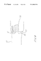
- FIG. 1 is a perspective drawing of the integrated propeller assembly with the propeller blades in folded configuration, with a shear pin intact.
- FIG. 2 is a perspective drawing of the integrated propeller assembly with the propeller blades in a deployed configuration, with a shear pin broken.
- FIG. 3 is a perspective drawing, from the underside of the integrated propeller assembly, with the propeller blades deployed, immediately before the breaking of a shear pin.
- FIG. 4 is a partial cross sectional view of the integrated propeller assembly with the propeller blades in a folded configuration.
- FIG. 5 is a partial cross section view of the integrated propeller assembly with the propeller blades in a deployed configuration, immediately before breaking the shear pin.
- FIG. 6 is a partial cross sectional view of another embodiment of a hub nut within the integrated propeller assembly with the propeller blades in a folded configuration.
- FIG. 7 is an exploded view of the adjustable mechanism illustrated in FIG. 6 .
- FIG. 1 is a perspective drawing of the integrated propeller assembly with the propeller blades in folded configuration, with a shear pin intact and
- FIG. 2 is a perspective drawing of the integrated propeller assembly with the propeller blades n a deployed configuration, with a shear pin broken.
- each propeller blade 12 in an integral unit that is comprised of a foil 13 , attachment shaft 14 , and propeller base 15 .
- Each propeller base 15 is located within a journal 17 in a propeller assembly hub, or propeller housing 20 .
- the propeller blades 12 are equally spaced from each other.
- the propeller assembly hub 20 is dome-like in shape with a conical sidewall extending downward from the base of the dome. As better illustrated in FIGS. 4 and 5, a shear pin 30 extends from the underside of the conical sidewall.
- a housing nut, or hub nut, 22 which is large enough in diameter to allow assembly of a bevel gearheaded drive shaft 26 , 27 as illustrated in FIG. 3 .
- the hub nut 22 also functions to pre-load the drive shaft bevel gear 26 into bevel gears 25 attached to the underside of each propeller base 15 , as illustrated in FIG. 3 .
- FIG. 3 is a perspective drawing, from the underside of the integrated propeller assembly, with the propeller blades deployed, immediately before the breaking of a shear pin.
- the embodiment of FIG. 3 includes a propeller blade bevel gear 25 that is connected to each propeller blade 12 .
- the propeller blade bevel gears 25 are engaged with a drive shaft bevel gear 26 . Since a gear does not need to be beveled 360° around the circumference, the propeller blade bevel gears 25 may be manufactured where, for example, only 180° of the gear is beveled.
- the drive shaft bevel gear 26 is an integral unit with a drive shaft 27 . One end of the drive shaft 27 extends to a prime mover (not shown) which is capable of rotating the drive shaft 27 .
- the other end extends into the housing nut 22 , as viewed in FIGS. 4 and 5.
- Extending from the base of the propeller assembly hub 20 is a shear pin 30 .
- the shear pin 30 fits within a cavity 35 located on the surface of a projectile 40 .
- the shear pin 30 statorizes the housing assembly 20 until the blades are deployed to a stop, which then causes the shear pin 30 to be severed by the continued rotation of the drive shaft 27 by the prime mover.
- FIG. 4 is a partial cross sectional view of the integrated propeller assembly with the propeller blades folded
- FIG. 5 is a partial cross sectional view of the propeller assembly with the propeller blades deployed.
- the embodiments of FIGS. 4 and 5 show an integrated drive shaft 27 and drive shaft bevel gear 26 .
- the outer circumference of the hub nut 22 is a threaded to match threads located within the opening or hole of the hub 20 which accepts the hub nut 22 .
- the housing nut 22 has a cavity 23 that is smooth to reduce friction.
- the end of the drive shaft 27 that fits within the cavity 23 is also smooth to reduce friction.
- a friction reducing device is used to further reduce friction.
- a drive shaft includes a cavity 51 for a ball bearing 53 located at the end of drive shaft through its axial center.
- a second cavity 55 is also included in the housing nut 22 to accept the ball bearing 53 .
- a substance, such as Teflon coats the cavity 23 within the hub nut 22 and/or the end of the drive shaft 27 that fits within the housing nut cavity 23 .
- a spring detent 28 Imbedded within the end of the drive shaft 27 that fits within the housing nut cavity 23 is a spring detent 28 .
- the bevel gear assembly 25 , 26 causes the integrated propeller blades 12 to nutate into a deployed configuration.
- the spring detent 28 is aligned with a receiving cavity 29 inside of the housing nut 22 and imbeds itself into the receiving cavity 29 .
- the propeller assembly 10 is free to turn with the drive shaft 27 except for the shear pin 30 holding the propeller assembly 10 stationary to the projectile 40 .
- the force applied by the rotating of the drive shaft and propeller assembly 10 , 27 stresses the shear pin 30 until the shear pin 30 breaks whereby the deployed propeller assembly 10 freely rotates with the drive shaft 27 .
- FIG. 6 is a partial cross sectional view of another embodiment of a hub nut within the integrated propeller assembly with the propeller blades in a folded configuration.
- the hub nut 22 is composed of an outer segment and an inner segment which is a spline 57 which is an axially translating nut that allows the spline to move in and out without rotary motion.
- the drive shaft 27 is threaded at an end 31 that fits within and engages the threads within the spline 57 .
- FIG. 7 is an exploded view of the adjustable mechanism illustrated in FIG. 6 .
- a mechanism 61 to adjust the maximum deployed position of the propeller blades after they nutate extends between the base of the spline 57 and a mating surface 59 on the drive shaft 27 .
- the adjustable mechanism is a bolt or screw having an end protruding from the spline 57 .
- An opposed end of the bolt or screw may be accessible from outside the propeller assembly 10 for precise adjustment of the position of the propeller 12 in the fully deployed position.
Abstract
Description
Claims (20)
Priority Applications (1)
| Application Number | Priority Date | Filing Date | Title |
|---|---|---|---|
| US09/447,972 US6308632B1 (en) | 1998-11-23 | 1999-11-22 | Deployable folded propeller assembly for aerial projectiles |
Applications Claiming Priority (2)
| Application Number | Priority Date | Filing Date | Title |
|---|---|---|---|
| US10937598P | 1998-11-23 | 1998-11-23 | |
| US09/447,972 US6308632B1 (en) | 1998-11-23 | 1999-11-22 | Deployable folded propeller assembly for aerial projectiles |
Publications (1)
| Publication Number | Publication Date |
|---|---|
| US6308632B1 true US6308632B1 (en) | 2001-10-30 |
Family
ID=26806911
Family Applications (1)
| Application Number | Title | Priority Date | Filing Date |
|---|---|---|---|
| US09/447,972 Expired - Fee Related US6308632B1 (en) | 1998-11-23 | 1999-11-22 | Deployable folded propeller assembly for aerial projectiles |
Country Status (1)
| Country | Link |
|---|---|
| US (1) | US6308632B1 (en) |
Cited By (38)
| Publication number | Priority date | Publication date | Assignee | Title |
|---|---|---|---|---|
| US20050223931A1 (en) * | 2004-04-08 | 2005-10-13 | Keith Michael A | Accuracy less lethal projectile |
| DE102004061977A1 (en) * | 2004-12-23 | 2006-07-06 | Lfk-Lenkflugkörpersysteme Gmbh | Small Missile |
| US20100012774A1 (en) * | 2006-05-15 | 2010-01-21 | Kazak Composites, Incorporated | Powered unmanned aerial vehicle |
| US20120199698A1 (en) * | 2009-03-05 | 2012-08-09 | Cranfield Aerospace Ltd | Unmanned air vehicle (uav), control system and method |
| US8525090B1 (en) * | 2010-06-23 | 2013-09-03 | The United States Of America As Represented By The Secretary Of The Army | Pneumatically actuated control surface for airframe body |
| US8900060B2 (en) | 2009-04-29 | 2014-12-02 | Ecp Entwicklungsgesellschaft Mbh | Shaft arrangement having a shaft which extends within a fluid-filled casing |
| US8926492B2 (en) | 2011-10-11 | 2015-01-06 | Ecp Entwicklungsgesellschaft Mbh | Housing for a functional element |
| US8932141B2 (en) | 2009-10-23 | 2015-01-13 | Ecp Entwicklungsgesellschaft Mbh | Flexible shaft arrangement |
| US8944748B2 (en) | 2009-05-05 | 2015-02-03 | Ecp Entwicklungsgesellschaft Mbh | Fluid pump changeable in diameter, in particular for medical application |
| US8979493B2 (en) | 2009-03-18 | 2015-03-17 | ECP Entwicklungsgesellscaft mbH | Fluid pump |
| US8998792B2 (en) | 2008-12-05 | 2015-04-07 | Ecp Entwicklungsgesellschaft Mbh | Fluid pump with a rotor |
| US9028216B2 (en) | 2009-09-22 | 2015-05-12 | Ecp Entwicklungsgesellschaft Mbh | Rotor for an axial flow pump for conveying a fluid |
| US9067006B2 (en) | 2009-06-25 | 2015-06-30 | Ecp Entwicklungsgesellschaft Mbh | Compressible and expandable blade for a fluid pump |
| US9089670B2 (en) | 2009-02-04 | 2015-07-28 | Ecp Entwicklungsgesellschaft Mbh | Catheter device having a catheter and an actuation device |
| US9089634B2 (en) | 2009-09-22 | 2015-07-28 | Ecp Entwicklungsgesellschaft Mbh | Fluid pump having at least one impeller blade and a support device |
| US9217442B2 (en) | 2010-03-05 | 2015-12-22 | Ecp Entwicklungsgesellschaft Mbh | Pump or rotary cutter for operation in a fluid |
| CN105241300A (en) * | 2015-10-10 | 2016-01-13 | 湖北三江航天红林探控有限公司 | Cutting-off type locking device |
| US9314558B2 (en) | 2009-12-23 | 2016-04-19 | Ecp Entwicklungsgesellschaft Mbh | Conveying blades for a compressible rotor |
| US9328741B2 (en) | 2010-05-17 | 2016-05-03 | Ecp Entwicklungsgesellschaft Mbh | Pump arrangement |
| US9339596B2 (en) | 2009-12-23 | 2016-05-17 | Ecp Entwicklungsgesellschaft Mbh | Radially compressible and expandable rotor for a fluid pump |
| US9358330B2 (en) | 2009-12-23 | 2016-06-07 | Ecp Entwicklungsgesellschaft Mbh | Pump device having a detection device |
| US9416783B2 (en) | 2009-09-22 | 2016-08-16 | Ecp Entwicklungsgellschaft Mbh | Compressible rotor for a fluid pump |
| US9416791B2 (en) | 2010-01-25 | 2016-08-16 | Ecp Entwicklungsgesellschaft Mbh | Fluid pump having a radially compressible rotor |
| US9603983B2 (en) | 2009-10-23 | 2017-03-28 | Ecp Entwicklungsgesellschaft Mbh | Catheter pump arrangement and flexible shaft arrangement having a core |
| US9611743B2 (en) | 2010-07-15 | 2017-04-04 | Ecp Entwicklungsgesellschaft Mbh | Radially compressible and expandable rotor for a pump having an impeller blade |
| US9616991B2 (en) | 2015-05-01 | 2017-04-11 | Peter Daniel WIRASNIK | Mechanically self-regulated propeller |
| US9771801B2 (en) | 2010-07-15 | 2017-09-26 | Ecp Entwicklungsgesellschaft Mbh | Rotor for a pump, produced with a first elastic material |
| US9867916B2 (en) | 2010-08-27 | 2018-01-16 | Berlin Heart Gmbh | Implantable blood conveying device, manipulating device and coupling device |
| US9895475B2 (en) | 2010-07-15 | 2018-02-20 | Ecp Entwicklungsgesellschaft Mbh | Blood pump for the invasive application within a body of a patient |
| US9974893B2 (en) | 2010-06-25 | 2018-05-22 | Ecp Entwicklungsgesellschaft Mbh | System for introducing a pump |
| US10107299B2 (en) | 2009-09-22 | 2018-10-23 | Ecp Entwicklungsgesellschaft Mbh | Functional element, in particular fluid pump, having a housing and a conveying element |
| US10172985B2 (en) | 2009-08-06 | 2019-01-08 | Ecp Entwicklungsgesellschaft Mbh | Catheter device having a coupling device for a drive device |
| WO2019085150A1 (en) * | 2017-10-31 | 2019-05-09 | 深圳市大疆创新科技有限公司 | Foldable propeller, and unmanned aerial vehicle |
| US10391278B2 (en) | 2011-03-10 | 2019-08-27 | Ecp Entwicklungsgesellschaft Mbh | Push device for the axial insertion of an elongate, flexible body |
| US10561773B2 (en) | 2011-09-05 | 2020-02-18 | Ecp Entwicklungsgesellschaft Mbh | Medical product comprising a functional element for the invasive use in a patient's body |
| US20230234696A1 (en) * | 2020-06-16 | 2023-07-27 | Safran Helicopter Engines | Propulsion unit with foldable propeller blades and method for folding the blades |
| US11873096B1 (en) | 2021-02-11 | 2024-01-16 | Cornerstone Research Group, Inc. | Aircraft wing and propulsion system |
| US11969560B2 (en) | 2009-02-04 | 2024-04-30 | Ecp Entwicklungsgesellschaft Mbh | Catheter device having a catheter and an actuation device |
Citations (12)
| Publication number | Priority date | Publication date | Assignee | Title |
|---|---|---|---|---|
| US866369A (en) * | 1907-02-23 | 1907-09-17 | Arthur W Learnard | Propeller. |
| US3709634A (en) | 1971-01-20 | 1973-01-09 | Michigan Wheel Corp | Folding blade propeller |
| US4072107A (en) * | 1967-06-07 | 1978-02-07 | The United States Of America As Represented By The Secretary Of The Army | Missile control means |
| US4204806A (en) | 1977-12-09 | 1980-05-27 | Outboard Marine Corporation | Folding propeller |
| US4364711A (en) * | 1980-01-16 | 1982-12-21 | Ab Volvo Penta | Folding boat propeller |
| US4726292A (en) * | 1985-06-28 | 1988-02-23 | Fratelli Borletti S.P.A. | Fuse for sub-munitions to be expelled from a rocket |
| US4768927A (en) | 1985-07-02 | 1988-09-06 | Confol Aps | Adjustable folding propeller |
| US4801243A (en) * | 1985-12-28 | 1989-01-31 | Bird-Johnson Company | Adjustable diameter screw propeller |
| US4936526A (en) | 1989-02-02 | 1990-06-26 | Williams International Corporation | Foldable counter-rotating propfan blades |
| US4986185A (en) | 1989-05-08 | 1991-01-22 | The United States Of America As Represented By The Secretary Of The Navy | Grenade device |
| US5299912A (en) * | 1992-07-28 | 1994-04-05 | United Technologies Corporation | Drive system for changing the diameter of a variable diameter rotor |
| US6152693A (en) * | 1993-12-23 | 2000-11-28 | Gori Marine As | Folding propeller |
-
1999
- 1999-11-22 US US09/447,972 patent/US6308632B1/en not_active Expired - Fee Related
Patent Citations (12)
| Publication number | Priority date | Publication date | Assignee | Title |
|---|---|---|---|---|
| US866369A (en) * | 1907-02-23 | 1907-09-17 | Arthur W Learnard | Propeller. |
| US4072107A (en) * | 1967-06-07 | 1978-02-07 | The United States Of America As Represented By The Secretary Of The Army | Missile control means |
| US3709634A (en) | 1971-01-20 | 1973-01-09 | Michigan Wheel Corp | Folding blade propeller |
| US4204806A (en) | 1977-12-09 | 1980-05-27 | Outboard Marine Corporation | Folding propeller |
| US4364711A (en) * | 1980-01-16 | 1982-12-21 | Ab Volvo Penta | Folding boat propeller |
| US4726292A (en) * | 1985-06-28 | 1988-02-23 | Fratelli Borletti S.P.A. | Fuse for sub-munitions to be expelled from a rocket |
| US4768927A (en) | 1985-07-02 | 1988-09-06 | Confol Aps | Adjustable folding propeller |
| US4801243A (en) * | 1985-12-28 | 1989-01-31 | Bird-Johnson Company | Adjustable diameter screw propeller |
| US4936526A (en) | 1989-02-02 | 1990-06-26 | Williams International Corporation | Foldable counter-rotating propfan blades |
| US4986185A (en) | 1989-05-08 | 1991-01-22 | The United States Of America As Represented By The Secretary Of The Navy | Grenade device |
| US5299912A (en) * | 1992-07-28 | 1994-04-05 | United Technologies Corporation | Drive system for changing the diameter of a variable diameter rotor |
| US6152693A (en) * | 1993-12-23 | 2000-11-28 | Gori Marine As | Folding propeller |
Cited By (98)
| Publication number | Priority date | Publication date | Assignee | Title |
|---|---|---|---|---|
| US8205556B1 (en) * | 2004-04-08 | 2012-06-26 | Keith Michael A | Accuracy less lethal projectile |
| US7278357B2 (en) * | 2004-04-08 | 2007-10-09 | Keith Michael A | Accuracy less lethal projectile |
| US20050223931A1 (en) * | 2004-04-08 | 2005-10-13 | Keith Michael A | Accuracy less lethal projectile |
| DE102004061977A1 (en) * | 2004-12-23 | 2006-07-06 | Lfk-Lenkflugkörpersysteme Gmbh | Small Missile |
| US20060255205A1 (en) * | 2004-12-23 | 2006-11-16 | Lfk-Lenkflugkoerpersysteme Gmbh | Small remotely controllable aircraft |
| DE102004061977B4 (en) * | 2004-12-23 | 2008-04-10 | Lfk-Lenkflugkörpersysteme Gmbh | Small Missile |
| US7854410B2 (en) * | 2006-05-15 | 2010-12-21 | Kazak Composites, Incorporated | Powered unmanned aerial vehicle |
| US20100012774A1 (en) * | 2006-05-15 | 2010-01-21 | Kazak Composites, Incorporated | Powered unmanned aerial vehicle |
| US8998792B2 (en) | 2008-12-05 | 2015-04-07 | Ecp Entwicklungsgesellschaft Mbh | Fluid pump with a rotor |
| US9964115B2 (en) | 2008-12-05 | 2018-05-08 | Ecp Entwicklungsgesellschaft Mbh | Fluid pump with a rotor |
| US10495101B2 (en) | 2008-12-05 | 2019-12-03 | Ecp Entwicklungsgesellschaft Mbh | Fluid pump with a rotor |
| US10662967B2 (en) | 2008-12-05 | 2020-05-26 | Ecp Entwicklungsgesellschaft Mbh | Fluid pump with a rotor |
| US11852155B2 (en) | 2008-12-05 | 2023-12-26 | Ecp Entwicklungsgesellschaft Mbh | Fluid pump with a rotor |
| US9404505B2 (en) | 2008-12-05 | 2016-08-02 | Ecp Entwicklungsgesellschaft Mbh | Fluid pump with a rotor |
| US9649475B2 (en) | 2009-02-04 | 2017-05-16 | Ecp Entwicklungsgesellschaft Mbh | Catheter device having a catheter and an actuation device |
| US9981110B2 (en) | 2009-02-04 | 2018-05-29 | Ecp Entwicklungsgesellschaft Mbh | Catheter device having a catheter and an actuation device |
| US9089670B2 (en) | 2009-02-04 | 2015-07-28 | Ecp Entwicklungsgesellschaft Mbh | Catheter device having a catheter and an actuation device |
| US10406323B2 (en) | 2009-02-04 | 2019-09-10 | Ecp Entwicklungsgesellschaft Mbh | Catheter device having a catheter and an actuation device |
| US11969560B2 (en) | 2009-02-04 | 2024-04-30 | Ecp Entwicklungsgesellschaft Mbh | Catheter device having a catheter and an actuation device |
| US11229774B2 (en) | 2009-02-04 | 2022-01-25 | Ecp Entwicklungsgesellschaft Mbh | Catheter device having a catheter and an actuation device |
| US20120199698A1 (en) * | 2009-03-05 | 2012-08-09 | Cranfield Aerospace Ltd | Unmanned air vehicle (uav), control system and method |
| US8979493B2 (en) | 2009-03-18 | 2015-03-17 | ECP Entwicklungsgesellscaft mbH | Fluid pump |
| US8900060B2 (en) | 2009-04-29 | 2014-12-02 | Ecp Entwicklungsgesellschaft Mbh | Shaft arrangement having a shaft which extends within a fluid-filled casing |
| US9512839B2 (en) | 2009-05-05 | 2016-12-06 | Ecp Entwicklungsgesellschaft Mbh | Fluid pump changeable in diameter, in particular for medical application |
| US11577066B2 (en) | 2009-05-05 | 2023-02-14 | Ecp Entwicklundgesellschaft Mbh | Fluid pump changeable in diameter, in particular for medical application |
| US11278711B2 (en) | 2009-05-05 | 2022-03-22 | Ecp Entwicklungsgesellschaft Mbh | Fluid pump changeable in diameter, in particular for medical application |
| US8944748B2 (en) | 2009-05-05 | 2015-02-03 | Ecp Entwicklungsgesellschaft Mbh | Fluid pump changeable in diameter, in particular for medical application |
| US10265448B2 (en) | 2009-05-05 | 2019-04-23 | Ecp Entwicklungsgesellschaft Mbh | Fluid pump changeable in diameter, in particular for medical application |
| US11786718B2 (en) | 2009-05-05 | 2023-10-17 | Ecp Entwicklungsgesellschaft Mbh | Fluid pump changeable in diameter, in particular for medical application |
| US10330101B2 (en) | 2009-06-25 | 2019-06-25 | Ecp Entwicklungsgesellschaft Mbh | Compressible and expandable blade for a fluid pump |
| US9067006B2 (en) | 2009-06-25 | 2015-06-30 | Ecp Entwicklungsgesellschaft Mbh | Compressible and expandable blade for a fluid pump |
| US11268521B2 (en) | 2009-06-25 | 2022-03-08 | Ecp Entwicklungsgesellschaft Mbh | Compressible and expandable blade for a fluid pump |
| US11116960B2 (en) | 2009-08-06 | 2021-09-14 | Ecp Entwicklungsgesellschaft Mbh | Catheter device having a coupling device for a drive device |
| US10172985B2 (en) | 2009-08-06 | 2019-01-08 | Ecp Entwicklungsgesellschaft Mbh | Catheter device having a coupling device for a drive device |
| US11773861B2 (en) | 2009-09-22 | 2023-10-03 | Ecp Entwicklungsgesellschaft Mbh | Compressible rotor for a fluid pump |
| US11592028B2 (en) | 2009-09-22 | 2023-02-28 | Ecp Entwicklungsgesellschaft Mbh | Fluid pump having at least one impeller blade and a support device |
| US9089634B2 (en) | 2009-09-22 | 2015-07-28 | Ecp Entwicklungsgesellschaft Mbh | Fluid pump having at least one impeller blade and a support device |
| US11421701B2 (en) | 2009-09-22 | 2022-08-23 | Ecp Entwicklungsgesellschaft Mbh | Compressible rotor for a fluid pump |
| US9416783B2 (en) | 2009-09-22 | 2016-08-16 | Ecp Entwicklungsgellschaft Mbh | Compressible rotor for a fluid pump |
| US10208763B2 (en) | 2009-09-22 | 2019-02-19 | Ecp Entwicklungsgesellschaft Mbh | Fluid pump having at least one impeller blade and a support device |
| US9028216B2 (en) | 2009-09-22 | 2015-05-12 | Ecp Entwicklungsgesellschaft Mbh | Rotor for an axial flow pump for conveying a fluid |
| US10107299B2 (en) | 2009-09-22 | 2018-10-23 | Ecp Entwicklungsgesellschaft Mbh | Functional element, in particular fluid pump, having a housing and a conveying element |
| US10792406B2 (en) | 2009-10-23 | 2020-10-06 | Ecp Entwicklungsgesellschaft Mbh | Catheter pump arrangement and flexible shaft arrangement having a core |
| US9603983B2 (en) | 2009-10-23 | 2017-03-28 | Ecp Entwicklungsgesellschaft Mbh | Catheter pump arrangement and flexible shaft arrangement having a core |
| US8932141B2 (en) | 2009-10-23 | 2015-01-13 | Ecp Entwicklungsgesellschaft Mbh | Flexible shaft arrangement |
| US11266824B2 (en) | 2009-12-23 | 2022-03-08 | Ecp Entwicklungsgesellschaft Mbh | Conveying blades for a compressible rotor |
| US11549517B2 (en) | 2009-12-23 | 2023-01-10 | Ecp Entwicklungsgesellschaft Mbh | Conveying blades for a compressible rotor |
| US9358330B2 (en) | 2009-12-23 | 2016-06-07 | Ecp Entwicklungsgesellschaft Mbh | Pump device having a detection device |
| US11773863B2 (en) | 2009-12-23 | 2023-10-03 | Ecp Entwicklungsgesellschaft Mbh | Conveying blades for a compressible rotor |
| US9339596B2 (en) | 2009-12-23 | 2016-05-17 | Ecp Entwicklungsgesellschaft Mbh | Radially compressible and expandable rotor for a fluid pump |
| US10806838B2 (en) | 2009-12-23 | 2020-10-20 | Ecp Entwicklungsgesellschaft Mbh | Conveying blades for a compressible rotor |
| US9903384B2 (en) | 2009-12-23 | 2018-02-27 | Ecp Entwicklungsgesellschaft Mbh | Radially compressible and expandable rotor for a fluid pump |
| US11781557B2 (en) | 2009-12-23 | 2023-10-10 | Ecp Entwicklungsgesellschaft Mbh | Radially compressible and expandable rotor for a fluid pump |
| US11434922B2 (en) | 2009-12-23 | 2022-09-06 | Ecp Entwicklungsgesellschaft Mbh | Radially compressible and expandable rotor for a fluid pump |
| US9314558B2 (en) | 2009-12-23 | 2016-04-19 | Ecp Entwicklungsgesellschaft Mbh | Conveying blades for a compressible rotor |
| US9795727B2 (en) | 2009-12-23 | 2017-10-24 | Ecp Entwicklungsgesellschaft Mbh | Pump device having a detection device |
| US11486400B2 (en) | 2009-12-23 | 2022-11-01 | Ecp Entwicklungsgesellschaft Mbh | Pump device having a detection device |
| US10557475B2 (en) | 2009-12-23 | 2020-02-11 | Ecp Entwicklungsgesellschaft Mbh | Radially compressible and expandable rotor for a fluid pump |
| US11815097B2 (en) | 2009-12-23 | 2023-11-14 | Ecp Entwicklungsgesellschaft Mbh | Pump device having a detection device |
| US10561772B2 (en) | 2009-12-23 | 2020-02-18 | Ecp Entwicklungsgesellschaft Mbh | Pump device having a detection device |
| US11517739B2 (en) | 2010-01-25 | 2022-12-06 | Ecp Entwicklungsgesellschaft Mbh | Fluid pump having a radially compressible rotor |
| US10316853B2 (en) | 2010-01-25 | 2019-06-11 | Ecp Entwicklungsgesellschaft Mbh | Fluid pump having a radially compressible rotor |
| US9416791B2 (en) | 2010-01-25 | 2016-08-16 | Ecp Entwicklungsgesellschaft Mbh | Fluid pump having a radially compressible rotor |
| US10413646B2 (en) | 2010-03-05 | 2019-09-17 | Ecp Entwicklungsgesellschaft Mbh | Pump or rotary cutter for operation in a fluid |
| US9217442B2 (en) | 2010-03-05 | 2015-12-22 | Ecp Entwicklungsgesellschaft Mbh | Pump or rotary cutter for operation in a fluid |
| US9907891B2 (en) | 2010-03-05 | 2018-03-06 | Ecp Entwicklungsgesellschaft Mbh | Pump or rotary cutter for operation in a fluid |
| US9328741B2 (en) | 2010-05-17 | 2016-05-03 | Ecp Entwicklungsgesellschaft Mbh | Pump arrangement |
| US10221866B2 (en) | 2010-05-17 | 2019-03-05 | Ecp Entwicklungsgesellschaft Mbh | Pump arrangement |
| US9759237B2 (en) | 2010-05-17 | 2017-09-12 | Ecp Entwicklungsgesellschaft Mbh | Pump arrangement |
| US11168705B2 (en) | 2010-05-17 | 2021-11-09 | Ecp Entwicklungsgesellschaft Mbh | Pump arrangement |
| US8525090B1 (en) * | 2010-06-23 | 2013-09-03 | The United States Of America As Represented By The Secretary Of The Army | Pneumatically actuated control surface for airframe body |
| US10898625B2 (en) | 2010-06-25 | 2021-01-26 | Ecp Entwicklungsgesellschaft Mbh | System for introducing a pump |
| US10874781B2 (en) | 2010-06-25 | 2020-12-29 | Ecp Entwicklungsgesellschaft Mbh | System for introducing a pump |
| US11957846B2 (en) | 2010-06-25 | 2024-04-16 | Ecp Entwicklungsgesellschaft Mbh | System for introducing a pump |
| US9974893B2 (en) | 2010-06-25 | 2018-05-22 | Ecp Entwicklungsgesellschaft Mbh | System for introducing a pump |
| US10589012B2 (en) | 2010-07-15 | 2020-03-17 | Ecp Entwicklungsgesellschaft Mbh | Blood pump for the invasive application within a body of a patient |
| US10920596B2 (en) | 2010-07-15 | 2021-02-16 | Ecp Entwicklungsgesellschaft Mbh | Radially compressible and expandable rotor for a pump having an impeller blade |
| US9771801B2 (en) | 2010-07-15 | 2017-09-26 | Ecp Entwicklungsgesellschaft Mbh | Rotor for a pump, produced with a first elastic material |
| US10584589B2 (en) | 2010-07-15 | 2020-03-10 | Ecp Entwicklungsgellschaft Mbh | Rotor for a pump having helical expandable blades |
| US11844939B2 (en) | 2010-07-15 | 2023-12-19 | Ecp Entwicklungsgesellschaft Mbh | Blood pump for the invasive application within a body of a patient |
| US9895475B2 (en) | 2010-07-15 | 2018-02-20 | Ecp Entwicklungsgesellschaft Mbh | Blood pump for the invasive application within a body of a patient |
| US11913467B2 (en) | 2010-07-15 | 2024-02-27 | Ecp Entwicklungsgesellschaft Mbh | Radially compressible and expandable rotor for a pump having an impeller blade |
| US11702938B2 (en) | 2010-07-15 | 2023-07-18 | Ecp Entwicklungsgesellschaft Mbh | Rotor for a pump, produced with a first elastic material |
| US9611743B2 (en) | 2010-07-15 | 2017-04-04 | Ecp Entwicklungsgesellschaft Mbh | Radially compressible and expandable rotor for a pump having an impeller blade |
| US11083885B2 (en) | 2010-08-27 | 2021-08-10 | Berlin Heart Gmbh | Implantable blood conveying device, manipulating device and coupling device |
| US9867916B2 (en) | 2010-08-27 | 2018-01-16 | Berlin Heart Gmbh | Implantable blood conveying device, manipulating device and coupling device |
| US11235125B2 (en) | 2011-03-10 | 2022-02-01 | Ecp Entwicklungsgesellschaft Mbh | Push device for the axial insertion of an elongate, flexible body |
| US10391278B2 (en) | 2011-03-10 | 2019-08-27 | Ecp Entwicklungsgesellschaft Mbh | Push device for the axial insertion of an elongate, flexible body |
| US11666746B2 (en) | 2011-09-05 | 2023-06-06 | Ecp Entwicklungsgesellschaft Mbh | Medical product comprising a functional element for the invasive use in a patient's body |
| US10561773B2 (en) | 2011-09-05 | 2020-02-18 | Ecp Entwicklungsgesellschaft Mbh | Medical product comprising a functional element for the invasive use in a patient's body |
| US8926492B2 (en) | 2011-10-11 | 2015-01-06 | Ecp Entwicklungsgesellschaft Mbh | Housing for a functional element |
| US9616991B2 (en) | 2015-05-01 | 2017-04-11 | Peter Daniel WIRASNIK | Mechanically self-regulated propeller |
| CN105241300A (en) * | 2015-10-10 | 2016-01-13 | 湖北三江航天红林探控有限公司 | Cutting-off type locking device |
| CN109952248A (en) * | 2017-10-31 | 2019-06-28 | 深圳市大疆创新科技有限公司 | A kind of folding paddle and unmanned vehicle |
| WO2019085150A1 (en) * | 2017-10-31 | 2019-05-09 | 深圳市大疆创新科技有限公司 | Foldable propeller, and unmanned aerial vehicle |
| US20230249812A1 (en) * | 2020-06-16 | 2023-08-10 | Safran Helicopter Engines | Propulsion unit with foldable propeller blades and method for folding the blades |
| US20230234696A1 (en) * | 2020-06-16 | 2023-07-27 | Safran Helicopter Engines | Propulsion unit with foldable propeller blades and method for folding the blades |
| US11873096B1 (en) | 2021-02-11 | 2024-01-16 | Cornerstone Research Group, Inc. | Aircraft wing and propulsion system |
Similar Documents
| Publication | Publication Date | Title |
|---|---|---|
| US6308632B1 (en) | Deployable folded propeller assembly for aerial projectiles | |
| US4667899A (en) | Double swing wing self-erecting missile wing structure | |
| EP1485668B1 (en) | Deployment mechanism for stowable fins in missiles | |
| US4869442A (en) | Self-deploying airfoil | |
| US5605308A (en) | Space vehicle dispenser | |
| EP1550837B1 (en) | Device for the deployment and the control of the control vanes of a projectile | |
| US5915694A (en) | Decoy utilizing infrared special material | |
| US8916810B2 (en) | Steerable spin-stabilized projectile | |
| US20080001023A1 (en) | Fin retention and deployment mechanism | |
| US4072107A (en) | Missile control means | |
| US4936526A (en) | Foldable counter-rotating propfan blades | |
| US11255648B2 (en) | Projectile with a range extending wing assembly | |
| US20040200375A1 (en) | Artillery projectile comprising an interchangeable payload | |
| FR2595809A1 (en) | BRAKING DEVICE FOR A ROTATION-STABILIZED PROJECTILE | |
| US4756253A (en) | Apparatus for deploying a flexible samara blade | |
| US20050082420A1 (en) | Deployment device for a fin | |
| EP1185837B1 (en) | Release mechanism in missile | |
| US7434762B2 (en) | Retractable thrust vector control vane system and method | |
| US7347147B2 (en) | Braking device for a trajectory-correctable spin-stabilized artillery projectile | |
| KR102081885B1 (en) | Unfolding wings apparatus of folding blade | |
| KR101924284B1 (en) | Canard deploying device and method of guided weapon | |
| US7100865B2 (en) | Method and apparatus for stowing and deploying control surfaces of a guided air vehicle | |
| US6505561B1 (en) | Method and apparatus for inducing rotation of a dispensed payload from non-spin projectiles | |
| JPH09159398A (en) | Wing unit for airframe | |
| USH776H (en) | Aerodynamic flail for a spinning projectile |
Legal Events
| Date | Code | Title | Description |
|---|---|---|---|
| AS | Assignment |
Owner name: INTERNATIONAL DYNAMICS CORPORATION, A FLORIDA CORP Free format text: ASSIGNMENT OF ASSIGNORS INTEREST;ASSIGNOR:SHAFFER, JAMES E.;REEL/FRAME:010414/0832 Effective date: 19991123 |
|
| FPAY | Fee payment |
Year of fee payment: 4 |
|
| REMI | Maintenance fee reminder mailed | ||
| LAPS | Lapse for failure to pay maintenance fees | ||
| REIN | Reinstatement after maintenance fee payment confirmed | ||
| FP | Lapsed due to failure to pay maintenance fee |
Effective date: 20091030 |
|
| FEPP | Fee payment procedure |
Free format text: PETITION RELATED TO MAINTENANCE FEES GRANTED (ORIGINAL EVENT CODE: PMFG); ENTITY STATUS OF PATENT OWNER: SMALL ENTITY Free format text: PETITION RELATED TO MAINTENANCE FEES FILED (ORIGINAL EVENT CODE: PMFP); ENTITY STATUS OF PATENT OWNER: SMALL ENTITY |
|
| PRDP | Patent reinstated due to the acceptance of a late maintenance fee |
Effective date: 20110614 |
|
| FPAY | Fee payment |
Year of fee payment: 8 |
|
| SULP | Surcharge for late payment | ||
| REMI | Maintenance fee reminder mailed | ||
| LAPS | Lapse for failure to pay maintenance fees | ||
| STCH | Information on status: patent discontinuation |
Free format text: PATENT EXPIRED DUE TO NONPAYMENT OF MAINTENANCE FEES UNDER 37 CFR 1.362 |
|
| FP | Lapsed due to failure to pay maintenance fee |
Effective date: 20131030 |