US6240798B1 - Reinforced anti-backlash nut with graduated thread depth fingers - Google Patents
Reinforced anti-backlash nut with graduated thread depth fingers Download PDFInfo
- Publication number
- US6240798B1 US6240798B1 US09/345,942 US34594299A US6240798B1 US 6240798 B1 US6240798 B1 US 6240798B1 US 34594299 A US34594299 A US 34594299A US 6240798 B1 US6240798 B1 US 6240798B1
- Authority
- US
- United States
- Prior art keywords
- longitudinal
- nut
- flexure
- flexure members
- backlash
- Prior art date
- Legal status (The legal status is an assumption and is not a legal conclusion. Google has not performed a legal analysis and makes no representation as to the accuracy of the status listed.)
- Expired - Lifetime
Links
- 230000013011 mating Effects 0.000 claims description 16
- 230000000295 complement effect Effects 0.000 claims description 10
- 230000002457 bidirectional effect Effects 0.000 claims 1
- 230000006835 compression Effects 0.000 description 7
- 238000007906 compression Methods 0.000 description 7
- 239000013598 vector Substances 0.000 description 7
- 238000005452 bending Methods 0.000 description 3
- 230000000712 assembly Effects 0.000 description 1
- 238000000429 assembly Methods 0.000 description 1
- 230000015572 biosynthetic process Effects 0.000 description 1
- 238000006243 chemical reaction Methods 0.000 description 1
- 238000010276 construction Methods 0.000 description 1
- 238000010586 diagram Methods 0.000 description 1
- 238000006073 displacement reaction Methods 0.000 description 1
- 230000000694 effects Effects 0.000 description 1
- 238000005755 formation reaction Methods 0.000 description 1
- 230000002093 peripheral effect Effects 0.000 description 1
- 230000036316 preload Effects 0.000 description 1
Images


Classifications
-
- F—MECHANICAL ENGINEERING; LIGHTING; HEATING; WEAPONS; BLASTING
- F16—ENGINEERING ELEMENTS AND UNITS; GENERAL MEASURES FOR PRODUCING AND MAINTAINING EFFECTIVE FUNCTIONING OF MACHINES OR INSTALLATIONS; THERMAL INSULATION IN GENERAL
- F16H—GEARING
- F16H25/00—Gearings comprising primarily only cams, cam-followers and screw-and-nut mechanisms
- F16H25/18—Gearings comprising primarily only cams, cam-followers and screw-and-nut mechanisms for conveying or interconverting oscillating or reciprocating motions
- F16H25/20—Screw mechanisms
- F16H25/2003—Screw mechanisms with arrangements for taking up backlash
- F16H25/2009—Screw mechanisms with arrangements for taking up backlash with radial preloading
-
- Y—GENERAL TAGGING OF NEW TECHNOLOGICAL DEVELOPMENTS; GENERAL TAGGING OF CROSS-SECTIONAL TECHNOLOGIES SPANNING OVER SEVERAL SECTIONS OF THE IPC; TECHNICAL SUBJECTS COVERED BY FORMER USPC CROSS-REFERENCE ART COLLECTIONS [XRACs] AND DIGESTS
- Y10—TECHNICAL SUBJECTS COVERED BY FORMER USPC
- Y10T—TECHNICAL SUBJECTS COVERED BY FORMER US CLASSIFICATION
- Y10T74/00—Machine element or mechanism
- Y10T74/19—Gearing
- Y10T74/19642—Directly cooperating gears
- Y10T74/19698—Spiral
- Y10T74/19702—Screw and nut
- Y10T74/19744—Rolling element engaging thread
-
- Y—GENERAL TAGGING OF NEW TECHNOLOGICAL DEVELOPMENTS; GENERAL TAGGING OF CROSS-SECTIONAL TECHNOLOGIES SPANNING OVER SEVERAL SECTIONS OF THE IPC; TECHNICAL SUBJECTS COVERED BY FORMER USPC CROSS-REFERENCE ART COLLECTIONS [XRACs] AND DIGESTS
- Y10—TECHNICAL SUBJECTS COVERED BY FORMER USPC
- Y10T—TECHNICAL SUBJECTS COVERED BY FORMER US CLASSIFICATION
- Y10T74/00—Machine element or mechanism
- Y10T74/19—Gearing
- Y10T74/1987—Rotary bodies
- Y10T74/19893—Sectional
- Y10T74/19898—Backlash take-up
- Y10T74/19902—Screw and nut
Definitions
- a linear positioning device which is stated to have an improved collar for use with a comparatively inexpensive rod having multiple grooves.
- the collar is telescoped over and adapted to be translated back and forth relative to the elongated rod.
- This collar includes cantilevered fingers which are resiliently wedged into angularly spaced grooves formed in the rod to preload the collar onto the rod and prevent rotational play from developing between the two.
- the collar is telescoped onto a rod in the form of a splined shaft while in another embodiment, the collar is a nut threaded onto a screw with multiple threads.
- U.S. Pat. No. 3,997,269 issued to Linley, an anti-backlash, self-aligning nut construction with specially constructed tubular nut bodies which co-act with concentric spring sleeves is described.
- the nut bodies in general, each have a pair of spring-biased elements provided with internal thread formations adapted for engagement with the external threads of a screw.
- a self-aligning spring sleeve is provided having solely three pairs of oppositely-disposed transverse slots to obtain the desired aligning features.
- the nut body has a base portion which is separated from the spring-biased elements by means of two transverse slots which, together with an adjacent pair of slots in the spring sleeve, form in effect a universal joint.
- One of the remaining slot pairs in the sleeve is oriented circumferentially with respect to the first pair by an angle of 90°, with a third pair of slots being circumferentially aligned with the first pair.
- an anti-backlash nut having oppositely-directed longitudinal flexure members has been disclosed in U.S. Pat. No. 4,210,033, which issued to the present inventors.
- This anti-backlash nut has a continuous portion extending longitudinally from one end of the screw to the other.
- there are at least two, and usually more, oppositely-directed longitudinal flexure members which have one end fixed to the anti-backlash nut and one end free-floating.
- the oppositely-directed longitudinal flexure members are biased towards the screw by one or more radial springs or other means for biasing.
- One style of anti-backlash nut has one or more longitudinal flexure members with one end of each member fixed and one end free floating in cantilever fashion.
- the nut including the flexure members, undergoes translational movement along a threaded shaft or lead screw.
- Each longitudinal flexure member has a ramp at its free-floating end.
- the nut is surrounded by an annular pressure applying ring which derives its force from a compression spring.
- the ring is constantly urged against the ramps which, in turn, creates radial force vectors to maintain the internal threads formed on the flexure members in contact with the threads of the shaft during operation and even after the nut has become worn.
- Such an anti-backlash nut is disclosed in our U.S. Pat. No. 4,249,426 which reissued as RE. 32,433.
- the threads on the shaft are in the form of a helix, as are the mating threads on the interior of the flexure members in the anti-backlash nut described in U.S. Pat. No. 4,249,426.
- a load is placed on the nut, as for example, when it is attached to a carriage or printer, there is a substantial force component acting axially on the shaft or lead screw and bearing on the threads of the flexure members.
- the axial force translates into two force vectors, one in the axial direction of the shaft and the other normal thereto, tangential to the shaft. This induces the cantilever mounted longitudinal flexure to deflect in a direction normal or tangential to the axis of the shaft. This can induce unwanted backlash.
- U.S. Pat. No. 5,027,671 discloses an anti-backlash nut with an annular member to counteract the unwanted backlash
- cooperating spline are provided on the longitudinal flexure members and on the annular member.
- the annular member surrounds the nut body to apply an external force radially inwardly to each of the ramps.
- the spline includes a longitudinal groove in each of the flexure members extending parallel to the axis of the screw and a complementary mating longitudinal ridge projecting from the annular member engageable within the groove.
- flanks tend to wear. Since the flanks are angularly disposed to the axis of rotation of the screw, upon wear the threads on the fingers drop more deeply into the threads of the screw and vice versa, until crests abut roots and flanks separate. The wear of the flanks thus contributes to axial play. To operate correctly and assure no backlash, both flanks of a thread must engage the flanks of adjacent threads on the mating part.
- an object of the present invention to provide an anti-backlash nut having longitudinal flexure members in which the flexure members are tailored to minimize radial play and achieve a radial and axial stiffness even as surfaces wear.
- the invention resides in an anti-backlash nut which moves along a lead screw in either of two longitudinal directions.
- the screw has an external helical thread and the nut has internal mating threads.
- the nut includes at least one longitudinal flexure member which has one end fixed to the nut body with the other end free-floating; typically at least two and preferably three flexure members are included.
- the longitudinal flexure members have inclined ramps on their outer surfaces. The ramps extend radially outward in a direction away from the fixed end.
- An annular member surrounding the nut body applies an external force radially inward to each of the ramps, the force being substantially constant in either direction of movement of the nut.
- the annular member is urged by a compression spring into engagement with the ramps.
- the axial force applied to the ramp urges the internal threads of the flexure members constantly into engagement with the external threads of the shaft to eliminate backlash.
- the interior threads of the anti-backlash nut are tapped out with increasing depth towards the free-floating end of the longitudinal flexure members.
- the mating, longitudinally-extending spline mechanism on the longitudinal flexure members and the annular force-applying member to impart rigidity to the longitudinal flexure members in a direction tangential to the longitudinal direction of the movement of the nut.
- FIG. 1 is a perspective view of an anti-backlash nut according to the invention
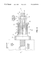
- FIG. 2 is a side elevation of the anti-backlash mechanism shown under load
- FIG. 3 is a force diagram of the mechanism under load
- FIG. 4 is an enlarged view of one of the longitudinal flexure members.
- FIG. 5 is a perspective view of a second embodiment of the present invention.
- an anti-backlash nut is generally designated 10 , and has a face plate 12 , a cylindrical projection 14 and a plurality of flexure members 16 , 18 and 20 .
- the face plate 12 is substantially triangular in shape, although it may be any convenient shape as determined by the load to which it is to be attached.
- the face plate 12 includes a plurality of holes 22 for securing the anti-backlash nut 10 .
- the anti-backlash nut 10 has a threaded bore 24 , as explained below in greater detail, to receive a lead screw 26 .
- the flexure members 16 , 18 , and 20 extend from a circumferentially continuous portion 28 to a segmented circumferential portion 30 .
- the three longitudinal flexure members 16 , 18 , and 20 are separated from each other by gaps 32 extending outwardly from the circumferentially continuous portion 28 .
- the segmented circumferential portion 30 at the free end of the nut is made up of three segments, one at the end of each of the longitudinal flexure members 16 , 18 and 20 which, respectively, have ramps 34 , 36 and 38 , near the outside surfaces of their free floating ends.
- the circumferential diameter of the segmented portion 30 is greater than that of the continuous portion 28 .
- the anti-backlash nut 10 has a force-applying sleeve 42 .
- the force-applying sleeve 42 is hollow and has a cylindrical portion 44 and a collar 46 .
- a compression spring 48 surrounds the cylindrical portion 44 and abuts the collar 46 when the sleeve 42 is assembled over the flexure members 16 , 18 , and 20 .
- the opposite end of the spring abuts a face 50 on the projection 14 or the face plate 12 , depending on the diameter of the spring.
- the anti-backlash nut 10 is hollow and inwardly threaded, as indicated at 24 in FIGS. 1 and 2. Its threads 24 are in engagement with the threads 27 on the lead screw 26 . Rotation of the lead screw in either a clockwise or counter-clockwise direction causes the anti-backlash nut to translate without rotation lengthwise of the anti-backlash nut 10 and when the face plate 12 of the anti-backlash nut 10 is attached to a load, it causes the load to reciprocate relative to the axis alpha ( ⁇ ) of the screw.
- the force applying sleeve 42 also referred to as a spline mechanism, comprises, in part, longitudinal grooves 56 formed in the surface 58 of each of the longitudinal flexure members 16 , 18 and 20 and extending parallel to the axis alpha.
- a spline mechanism comprises, in part, longitudinal grooves 56 formed in the surface 58 of each of the longitudinal flexure members 16 , 18 and 20 and extending parallel to the axis alpha.
- the reactive forces to the load will be seen acting on the interior threads 24 of the longitudinal flexure members 16 , 18 , and 20 of the anti-backlash nut 10 .
- the normal force vector F n causes the flexure members 16 , 18 , and 20 to be bent or induced away from the parallelism with the axis alpha in the direction of the arrow designated “direction of induced bending”.
- This force is inclined to separate the threads 24 of the anti-backlash nut 10 on the inner side of the flexure members 16 , 18 and 20 from the threads 27 on the lead screw 26 , with a potential result of induced backlash.
- the resultant normal force vector F n which induces bending of the flexure members 16 , 18 and 20 in a direction tangential to the axis alpha, is counter-acted by the ridges 60 on the sleeve 42 preventing the flexure members from being displaced.
- the sleeve 42 surrounding this flexure member resists displacement due to its rigidity and its resistance to tangential compression. This not only increases wear life of the product, but prevents inadvertent backlash from being created.
- the threads 24 of the flexure member 16 have a varying depth.
- a thread has a depth that is measured from the tip 64 to the root 66 of the thread.
- the root of the thread is deeper as you move from the circumferentially continuous portion 28 to the segmented circumferential portion 30 .
- the threads nearest the cantilevered end of the nut fingers contribute more to radial stability, where the nut is less compliant and wear is less.
- the threads near the free ends of the fingers afford more axial stability. More flank wear occurs closer to the free ends of the fingers since it is this end of the nut fingers where radial pressure is applied through the conical ramps being pressed toward the axis of the screw. Maintaining flank-to-flank engagement by increasing depth of the roots is more important at the free end. Thus, the threads are “tapped out” with increasing depth toward the free end to gain the best compromise solution.
- the force-applying sleeve 42 keeps the tip of the threads of the flexure member in contact.
- the fixed end provides the radial stiffness; the free end provides the axial stiffness.
- the clamping pressure of the ring is not as great as an inherent rigidity or stiffness of the anchored ends.
- the anti-backlash nut 70 has a face plate 72 , a cylindrical projection 74 and a plurality of flexure members 76 , 78 and 80 .
- the face plate 72 includes a plurality of holes 82 for securing the anti-backlash nut 70 .
- the flexure members 76 , 78 , and 80 extend from a circumferentially continuous portion 88 to a segmented circumferential portion 90 .
- the three longitudinal flexure members 76 , 78 , and 80 are separated from each other by gaps 92 extending outwardly from the circumferentially continuous portion 88 .
- Each of the longitudinal flexure members 76 , 78 and 80 respectively, has ramps 94 , 96 and 98 , near the outside surfaces of their free floating ends.
- the anti-backlash nut 70 has a force-applying sleeve 102 .
- the force applying sleeve 102 is hollow and has a cylindrical portion 104 and a collar 106 .
- a compression spring 108 surrounds the cylindrical portion 104 and abuts the collar 106 .
- the face of the collar of the sleeve 102 is urged continuously against the ramps 94 , 96 , and 98 to cause the flexure members 76 , 78 , and 80 to be constantly urged inwardly toward the axis alpha to compensate for wear and to reduce backlash between the threads 84 of the anti-backlash nut 70 and the threads 87 of the lead screw 86 .
- the force-applying sleeve 102 also referred to as a spline mechanism, includes longitudinally extending parallel ridges 110 on each of the flexure members 76 , 78 , and 80 .
- the parallel ridges 110 extend parallel to the axis alpha ( ⁇ ) and are located radially outwardly thereof.
- There are ramp portions 110 on the ridges which are the equivalent of the ramps 16 , 18 and 20 of the previous embodiment.
- the ridges 110 engage within the grooves 112 when the sleeve 102 is assembled over the flexure members similar to the previous embodiment.
- the splined sleeve grooves and ridges prevent the flexure members, under the induced direction of bending, from deflecting out of parallelism with the axis alpha ( ⁇ ).
Landscapes
- Engineering & Computer Science (AREA)
- General Engineering & Computer Science (AREA)
- Mechanical Engineering (AREA)
- Transmission Devices (AREA)
Abstract
Description
Claims (11)
Priority Applications (1)
| Application Number | Priority Date | Filing Date | Title |
|---|---|---|---|
| US09/345,942 US6240798B1 (en) | 1999-07-01 | 1999-07-01 | Reinforced anti-backlash nut with graduated thread depth fingers |
Applications Claiming Priority (1)
| Application Number | Priority Date | Filing Date | Title |
|---|---|---|---|
| US09/345,942 US6240798B1 (en) | 1999-07-01 | 1999-07-01 | Reinforced anti-backlash nut with graduated thread depth fingers |
Publications (1)
| Publication Number | Publication Date |
|---|---|
| US6240798B1 true US6240798B1 (en) | 2001-06-05 |
Family
ID=23357207
Family Applications (1)
| Application Number | Title | Priority Date | Filing Date |
|---|---|---|---|
| US09/345,942 Expired - Lifetime US6240798B1 (en) | 1999-07-01 | 1999-07-01 | Reinforced anti-backlash nut with graduated thread depth fingers |
Country Status (1)
| Country | Link |
|---|---|
| US (1) | US6240798B1 (en) |
Cited By (24)
| Publication number | Priority date | Publication date | Assignee | Title |
|---|---|---|---|---|
| US20050132831A1 (en) * | 2003-10-17 | 2005-06-23 | Michael Scholz | Catch nut |
| US20050178225A1 (en) * | 2004-02-17 | 2005-08-18 | Kerk Motion Products, Inc. | Long-span lead screw assembly with anti-backlash nut |
| WO2005036026A3 (en) * | 2003-09-30 | 2005-11-03 | Tritex Corp | Anti-backlash nut assembly for a lead screw |
| US20070258789A1 (en) * | 2004-10-01 | 2007-11-08 | Michael Bogue | Antiback-Lash Nut |
| WO2007136557A2 (en) * | 2006-05-19 | 2007-11-29 | Kerk Motion Products, Inc. | Lead screw actuator with torsional anti-backlash nut |
| US20080115605A1 (en) * | 2006-11-16 | 2008-05-22 | Erikson Kenneth W | Motor assembly with anti-backlash nut and thermal insensitive mechanism |
| US20090126521A1 (en) * | 2007-11-21 | 2009-05-21 | Pacific Bearing Company | Nut With Flexible Gripping Fingers And Apparatus |
| US20090145252A1 (en) * | 2007-12-10 | 2009-06-11 | Pacific Bearing Company | Anti-Backlash Nut, Lead Screw Assembly And Method |
| US20090249910A1 (en) * | 2008-04-04 | 2009-10-08 | Kerk Motion Products, Inc. | Lead screw device |
| US20100272503A1 (en) * | 2009-04-22 | 2010-10-28 | As Ip Holdco, L.L.C. | Push and Turn Nut for Quick Faucet Installation |
| US20130133448A1 (en) * | 2011-11-28 | 2013-05-30 | Pacific Bearing Company | Inverted spline rail system |
| US8794892B1 (en) * | 2011-06-21 | 2014-08-05 | The United States Of America As Represented By The Secretary Of The Navy | Torque nut assembly |
| US9010205B2 (en) | 2011-01-20 | 2015-04-21 | Pacific Bearing Company | Linear slide having integral carriage and nut assembly |
| US20150300466A1 (en) * | 2014-04-21 | 2015-10-22 | Helix Linear Technologies | Anti-backlash nut assembly |
| US20150367752A1 (en) * | 2014-06-20 | 2015-12-24 | Hyundai Dymos Incorporated | Apparatus for moving motor-operated seat rail |
| US9243697B2 (en) | 2011-12-23 | 2016-01-26 | Pacific Bearing Company | Nut with flexible fingers and radial compression members |
| US9334937B2 (en) | 2013-07-03 | 2016-05-10 | Pacific Bearing Company | Floating nut and carriage assembly |
| US9835281B2 (en) | 2011-08-24 | 2017-12-05 | As Ip Holdco, Llc | No-tools spread faucet assembly, kits and methods |
| US10047890B2 (en) | 2011-03-08 | 2018-08-14 | As Ip Holdco, Llc | Quick connection coupling |
| CN109923332A (en) * | 2016-11-07 | 2019-06-21 | 大陆汽车有限公司 | The manufacturing method of linear drive apparatus, motor and linear drive apparatus |
| US11148213B2 (en) | 2019-01-03 | 2021-10-19 | Kennametal Inc. | Hardware fastener with movable threaded element and one or more spring-like members |
| US11268607B1 (en) * | 2016-02-17 | 2022-03-08 | Helix Linear Technologies | Lead screw nuts having threads formed from different materials |
| US20220154807A1 (en) * | 2020-11-19 | 2022-05-19 | Pacific Bearing Corp. | Nut with flexible fingers and self-aligning members |
| USD1016599S1 (en) | 2017-02-17 | 2024-03-05 | Helix Linear Technologies | Nut |
Citations (7)
| Publication number | Priority date | Publication date | Assignee | Title |
|---|---|---|---|---|
| US4131031A (en) | 1977-07-19 | 1978-12-26 | Kerk Motion Products, Inc. | Anti-backlash nut assembly |
| US4353264A (en) | 1980-09-22 | 1982-10-12 | Erikson Keith W | Anti-backlash nut assembly |
| US4566345A (en) | 1984-07-23 | 1986-01-28 | Erikson Kenneth W | Tool carrier assembly |
| USRE32433E (en) | 1978-07-17 | 1987-06-09 | Kerk Motion Products, Inc. | Anti-backlash nut having longitudinal flexural members with ramps thereon and means to apply an axial pre-load force to said ramps |
| US5027671A (en) | 1990-06-18 | 1991-07-02 | Kerk Motion Products, Inc. | Reinforced anti-backlash nut |
| US5913940A (en) | 1997-03-06 | 1999-06-22 | Kerk Motion Products, Inc. | Adjustable preload anti-backlash nut |
| US5937702A (en) | 1998-04-14 | 1999-08-17 | Kerk Motion Products, Inc. | Spring bias wedge in reinforcing rail |
-
1999
- 1999-07-01 US US09/345,942 patent/US6240798B1/en not_active Expired - Lifetime
Patent Citations (7)
| Publication number | Priority date | Publication date | Assignee | Title |
|---|---|---|---|---|
| US4131031A (en) | 1977-07-19 | 1978-12-26 | Kerk Motion Products, Inc. | Anti-backlash nut assembly |
| USRE32433E (en) | 1978-07-17 | 1987-06-09 | Kerk Motion Products, Inc. | Anti-backlash nut having longitudinal flexural members with ramps thereon and means to apply an axial pre-load force to said ramps |
| US4353264A (en) | 1980-09-22 | 1982-10-12 | Erikson Keith W | Anti-backlash nut assembly |
| US4566345A (en) | 1984-07-23 | 1986-01-28 | Erikson Kenneth W | Tool carrier assembly |
| US5027671A (en) | 1990-06-18 | 1991-07-02 | Kerk Motion Products, Inc. | Reinforced anti-backlash nut |
| US5913940A (en) | 1997-03-06 | 1999-06-22 | Kerk Motion Products, Inc. | Adjustable preload anti-backlash nut |
| US5937702A (en) | 1998-04-14 | 1999-08-17 | Kerk Motion Products, Inc. | Spring bias wedge in reinforcing rail |
Cited By (41)
| Publication number | Priority date | Publication date | Assignee | Title |
|---|---|---|---|---|
| WO2005036026A3 (en) * | 2003-09-30 | 2005-11-03 | Tritex Corp | Anti-backlash nut assembly for a lead screw |
| US20070012127A1 (en) * | 2003-09-30 | 2007-01-18 | Frank Morton | Anti-backlash nut assembly for a lead screw |
| US7458292B2 (en) * | 2003-10-17 | 2008-12-02 | Rexroth Star Gmbh | Catch nut |
| US20050132831A1 (en) * | 2003-10-17 | 2005-06-23 | Michael Scholz | Catch nut |
| US20080022794A1 (en) * | 2004-02-17 | 2008-01-31 | Erikson Keith W | Long-span lead screw assembly with anti-backlash nut |
| US7219570B2 (en) | 2004-02-17 | 2007-05-22 | Kerk Motion Products, Inc. | Long-span lead screw assembly with anti-backlash nut |
| US20050178225A1 (en) * | 2004-02-17 | 2005-08-18 | Kerk Motion Products, Inc. | Long-span lead screw assembly with anti-backlash nut |
| US7552657B2 (en) | 2004-02-17 | 2009-06-30 | Kerk Motion Products, Inc. | Long-span lead screw assembly with anti-backlash nut |
| US7841251B2 (en) | 2004-10-01 | 2010-11-30 | Tritex Corporation | Antiback-lash nut |
| US20070258789A1 (en) * | 2004-10-01 | 2007-11-08 | Michael Bogue | Antiback-Lash Nut |
| GB2451610B (en) * | 2006-05-19 | 2011-02-16 | Kerk Motion Prod | Lead screw actuator with torsional anti-backlash nut |
| GB2451610A (en) * | 2006-05-19 | 2009-02-04 | Kerk Motion Prod | Lead screw actuator with torsional anti-backlash nut |
| WO2007136557A3 (en) * | 2006-05-19 | 2008-01-24 | Kerk Motion Prod | Lead screw actuator with torsional anti-backlash nut |
| WO2007136557A2 (en) * | 2006-05-19 | 2007-11-29 | Kerk Motion Products, Inc. | Lead screw actuator with torsional anti-backlash nut |
| US20080115605A1 (en) * | 2006-11-16 | 2008-05-22 | Erikson Kenneth W | Motor assembly with anti-backlash nut and thermal insensitive mechanism |
| US7891265B2 (en) | 2006-11-16 | 2011-02-22 | Haydon Kerk Motion Solutions, Inc. | Motor assembly with anti-backlash nut and thermal insensitive mechanism |
| US20090126521A1 (en) * | 2007-11-21 | 2009-05-21 | Pacific Bearing Company | Nut With Flexible Gripping Fingers And Apparatus |
| US8028594B2 (en) | 2007-11-21 | 2011-10-04 | Pacific Bearing Company | Nut with flexible gripping fingers and apparatus |
| US7992456B2 (en) | 2007-12-10 | 2011-08-09 | Pacific Bearing Company | Anti-backlash nut, lead screw assembly and method |
| US20090145252A1 (en) * | 2007-12-10 | 2009-06-11 | Pacific Bearing Company | Anti-Backlash Nut, Lead Screw Assembly And Method |
| US20090249910A1 (en) * | 2008-04-04 | 2009-10-08 | Kerk Motion Products, Inc. | Lead screw device |
| US20100272503A1 (en) * | 2009-04-22 | 2010-10-28 | As Ip Holdco, L.L.C. | Push and Turn Nut for Quick Faucet Installation |
| US8231318B2 (en) * | 2009-04-22 | 2012-07-31 | As Ip Holdco, L.L.C. | Push and turn nut for quick faucet installation |
| US9010205B2 (en) | 2011-01-20 | 2015-04-21 | Pacific Bearing Company | Linear slide having integral carriage and nut assembly |
| US10047890B2 (en) | 2011-03-08 | 2018-08-14 | As Ip Holdco, Llc | Quick connection coupling |
| US8794892B1 (en) * | 2011-06-21 | 2014-08-05 | The United States Of America As Represented By The Secretary Of The Navy | Torque nut assembly |
| US9835281B2 (en) | 2011-08-24 | 2017-12-05 | As Ip Holdco, Llc | No-tools spread faucet assembly, kits and methods |
| US9303742B2 (en) * | 2011-11-28 | 2016-04-05 | Pacific Bearing Company | Inverted spline rail system |
| US20130133448A1 (en) * | 2011-11-28 | 2013-05-30 | Pacific Bearing Company | Inverted spline rail system |
| US9243697B2 (en) | 2011-12-23 | 2016-01-26 | Pacific Bearing Company | Nut with flexible fingers and radial compression members |
| US9334937B2 (en) | 2013-07-03 | 2016-05-10 | Pacific Bearing Company | Floating nut and carriage assembly |
| US9618104B2 (en) * | 2014-04-21 | 2017-04-11 | Helix Linear Technologies | Anti-backlash nut assembly |
| US20150300466A1 (en) * | 2014-04-21 | 2015-10-22 | Helix Linear Technologies | Anti-backlash nut assembly |
| US20150367752A1 (en) * | 2014-06-20 | 2015-12-24 | Hyundai Dymos Incorporated | Apparatus for moving motor-operated seat rail |
| US11268607B1 (en) * | 2016-02-17 | 2022-03-08 | Helix Linear Technologies | Lead screw nuts having threads formed from different materials |
| CN109923332A (en) * | 2016-11-07 | 2019-06-21 | 大陆汽车有限公司 | The manufacturing method of linear drive apparatus, motor and linear drive apparatus |
| CN109923332B (en) * | 2016-11-07 | 2022-06-14 | 大陆汽车有限公司 | Linear drive device, motor, and method for manufacturing linear drive device |
| USD1016599S1 (en) | 2017-02-17 | 2024-03-05 | Helix Linear Technologies | Nut |
| US11148213B2 (en) | 2019-01-03 | 2021-10-19 | Kennametal Inc. | Hardware fastener with movable threaded element and one or more spring-like members |
| US20220154807A1 (en) * | 2020-11-19 | 2022-05-19 | Pacific Bearing Corp. | Nut with flexible fingers and self-aligning members |
| US11598400B2 (en) * | 2020-11-19 | 2023-03-07 | Pacific Bearing Corporation | Nut with flexible fingers and self-aligning members |
Similar Documents
| Publication | Publication Date | Title |
|---|---|---|
| US6240798B1 (en) | Reinforced anti-backlash nut with graduated thread depth fingers | |
| US5027671A (en) | Reinforced anti-backlash nut | |
| EP0016797B1 (en) | Anti-backlash nut | |
| US4210033A (en) | Anti-backlash nut | |
| USRE32433E (en) | Anti-backlash nut having longitudinal flexural members with ramps thereon and means to apply an axial pre-load force to said ramps | |
| US20070295128A1 (en) | Lead screw actuator with torsional anti-backlash nut | |
| US4131031A (en) | Anti-backlash nut assembly | |
| US6131478A (en) | Anti-backlash nut assembly | |
| US5303606A (en) | Anti-backlash nut having a free floating insert for applying an axial force to a lead screw | |
| US5695297A (en) | Mounting device | |
| EP2146180B1 (en) | Inside diameter measuring tool | |
| WO1998015742A1 (en) | Mounting device | |
| JPS5948886B2 (en) | Friction joint device | |
| US11686371B2 (en) | Coaxial gear mechanism | |
| JP3715038B2 (en) | Backlash removal feed screw device | |
| US4224831A (en) | Device for transferring a rotational motion into a longitudinal movement or vice versa | |
| US20210131546A1 (en) | Gearing | |
| JPH0316541B2 (en) | ||
| CN108367415B (en) | Power wrench with angle transmission device | |
| US20020020234A1 (en) | Self-aligning decoupled nut mechanism | |
| US2885872A (en) | Universal drive coupling | |
| KR100657657B1 (en) | Bearing screw type transferring | |
| KR20020073245A (en) | Apparatus for driving linear motion | |
| EP3263950B1 (en) | Centralizing bushing assembly | |
| US3844138A (en) | Connecting device |
Legal Events
| Date | Code | Title | Description |
|---|---|---|---|
| AS | Assignment |
Owner name: KERK MOTION PRODUCTS, INC., NEW HAMPSHIRE Free format text: ASSIGNMENT OF ASSIGNORS INTEREST;ASSIGNORS:ERIKSON, KENNETH W.;ERIKSON, KEITH W.;REEL/FRAME:010208/0465 Effective date: 19990818 |
|
| STCF | Information on status: patent grant |
Free format text: PATENTED CASE |
|
| FPAY | Fee payment |
Year of fee payment: 4 |
|
| AS | Assignment |
Owner name: THE GOVERNOR AND COMPANY OF THE BANK OF IRELAND, I Free format text: SECURITY AGREEMENT;ASSIGNORS:TRITEX CORPORATION;KERK MOTION PRODUCTS, INC.;HAYDON SWITCH & INSTRUMENT, INC.;AND OTHERS;REEL/FRAME:021006/0395 Effective date: 20080501 |
|
| FPAY | Fee payment |
Year of fee payment: 8 |
|
| AS | Assignment |
Owner name: HAYDON KERK MOTION SOLUTIONS, INC., CONNECTICUT Free format text: CHANGE OF NAME;ASSIGNOR:KERK MOTION PRODUCTS, INC.;REEL/FRAME:022928/0807 Effective date: 20090630 |
|
| FPAY | Fee payment |
Year of fee payment: 12 |