US6188848B1 - Camera having a data imprinting device - Google Patents
Camera having a data imprinting device Download PDFInfo
- Publication number
- US6188848B1 US6188848B1 US09/414,064 US41406499A US6188848B1 US 6188848 B1 US6188848 B1 US 6188848B1 US 41406499 A US41406499 A US 41406499A US 6188848 B1 US6188848 B1 US 6188848B1
- Authority
- US
- United States
- Prior art keywords
- film
- counter
- sprocket
- data
- frame
- Prior art date
- Legal status (The legal status is an assumption and is not a legal conclusion. Google has not performed a legal analysis and makes no representation as to the accuracy of the status listed.)
- Expired - Lifetime
Links
Images


Classifications
-
- G—PHYSICS
- G03—PHOTOGRAPHY; CINEMATOGRAPHY; ANALOGOUS TECHNIQUES USING WAVES OTHER THAN OPTICAL WAVES; ELECTROGRAPHY; HOLOGRAPHY
- G03B—APPARATUS OR ARRANGEMENTS FOR TAKING PHOTOGRAPHS OR FOR PROJECTING OR VIEWING THEM; APPARATUS OR ARRANGEMENTS EMPLOYING ANALOGOUS TECHNIQUES USING WAVES OTHER THAN OPTICAL WAVES; ACCESSORIES THEREFOR
- G03B17/00—Details of cameras or camera bodies; Accessories therefor
- G03B17/24—Details of cameras or camera bodies; Accessories therefor with means for separately producing marks on the film, e.g. title, time of exposure
-
- G—PHYSICS
- G03—PHOTOGRAPHY; CINEMATOGRAPHY; ANALOGOUS TECHNIQUES USING WAVES OTHER THAN OPTICAL WAVES; ELECTROGRAPHY; HOLOGRAPHY
- G03B—APPARATUS OR ARRANGEMENTS FOR TAKING PHOTOGRAPHS OR FOR PROJECTING OR VIEWING THEM; APPARATUS OR ARRANGEMENTS EMPLOYING ANALOGOUS TECHNIQUES USING WAVES OTHER THAN OPTICAL WAVES; ACCESSORIES THEREFOR
- G03B1/00—Film strip handling
- G03B1/60—Measuring or indicating length of the used or unused film; Counting number of exposures
-
- G—PHYSICS
- G03—PHOTOGRAPHY; CINEMATOGRAPHY; ANALOGOUS TECHNIQUES USING WAVES OTHER THAN OPTICAL WAVES; ELECTROGRAPHY; HOLOGRAPHY
- G03B—APPARATUS OR ARRANGEMENTS FOR TAKING PHOTOGRAPHS OR FOR PROJECTING OR VIEWING THEM; APPARATUS OR ARRANGEMENTS EMPLOYING ANALOGOUS TECHNIQUES USING WAVES OTHER THAN OPTICAL WAVES; ACCESSORIES THEREFOR
- G03B17/00—Details of cameras or camera bodies; Accessories therefor
- G03B17/42—Interlocking between shutter operation and advance of film or change of plate or cut-film
- G03B17/425—Interlocking between shutter operation and advance of film or change of plate or cut-film motor drive cameras
-
- G—PHYSICS
- G03—PHOTOGRAPHY; CINEMATOGRAPHY; ANALOGOUS TECHNIQUES USING WAVES OTHER THAN OPTICAL WAVES; ELECTROGRAPHY; HOLOGRAPHY
- G03B—APPARATUS OR ARRANGEMENTS FOR TAKING PHOTOGRAPHS OR FOR PROJECTING OR VIEWING THEM; APPARATUS OR ARRANGEMENTS EMPLOYING ANALOGOUS TECHNIQUES USING WAVES OTHER THAN OPTICAL WAVES; ACCESSORIES THEREFOR
- G03B2217/00—Details of cameras or camera bodies; Accessories therefor
- G03B2217/24—Details of cameras or camera bodies; Accessories therefor with means for separately producing marks on the film
- G03B2217/242—Details of the marking device
- G03B2217/243—Optical devices
Definitions
- the present invention relates to a camera provided with data imprinting device for imprinting photographic data such as a date, time, shutter speed, aperture value, etc., on film.
- a camera provided with a data imprinting device which stores photographic data such as a date, time, shutter speed, aperture value, etc., in a memory each time the shutter is released and subsequently reads out the stored data to imprint the same on film in predetermined areas thereof at the time of rewinding the film, is known in the art.
- a method of detecting the trailing edge of the last frame is disclosed in Japanese Laid-open Patent Publication No.63-177120 in which two pulses of different phases are generated by a mechanism composed of a gear, a printed circuit board, and a brush which slidably contacts the printed circuit board.
- the gear rotates in accordance with the movement of the film to rotate the brush relative to the printed circuit board so that the levels of the two pulses become high simultaneously only at each moment the border between two adjacent frames passes a predetermined position.
- the trailing edge of the last frame is detected at the time of rewinding the film by monitoring the levels of the two pulses.
- the trailing edge of the last frame cannot be detected precisely. Accordingly, such a conventional method of detecting the trailing edge of the last frame is not suitable for the case where photographic data is imprinted on film in a narrow area between two adjacent sprocket holes thereof.
- the primary object of the present invention is to provide a camera having a data imprinting device which can imprint photographic data on each frame precisely and accurately in a predetermined area between two adjacent sprocket holes thereof at the time of rewinding the film.
- a camera having a data imprinting function including: a motorized film transport device for winding and rewinding a film having consecutive sprocket holes; a sprocket-hole detecting device which detects that each of the sprocket holes passes a predetermined position; a memory in which photographic data of a frame of the film is stored at a shutter release; a data imprinting device which reads out one of the photographic data stored in the memory therefrom to imprint one character of the photographic data on a corresponding frame of the film between two adjacent sprocket holes of the corresponding frame; a film moving amount detector for detecting an amount of movement of part of the film which extends from the trailing edge of the last frame of the film to the end of the film, in accordance with detection of the sprocket-hole detector, wherein the amount of movement, which is detected by the film moving amount detector, is stored in the memory; a frame edge detector which detect
- the sprocket-hole detector detects that each of the sprocket holes passes the predetermined position by detecting the consecutive edges of the sprocket holes.
- the data imprinting device determines a position of commencement of imprinting each of the photographic data with reference to the trailing edge of the last frame detected by the frame edge detector, in accordance with the amount of movement stored in the memory.
- a counter for counting the sprocket holes detected by the sprocket-hole detector; wherein the film moving amount detector detects the amount of movement of the part of the film in accordance with the number of the sprocket holes counted by the counter.
- the memory includes a non-volatile memory.
- the film moving amount detector determines that the film is fully wound up to the end of the film when the film is rewound by the motorized film transport device after the shutter release if the sprocket-hole detector only detects a number of the sprocket holes which is fewer than a predetermined number of the sprocket holes provided on each frame of the film within a predetermined period of time.
- a film speed detecting device which detects the speed of the film; wherein the data imprinting device determines a position of commencement of imprinting the each of the photographic data in accordance with the time of detection of the sprocket-hole detector and the film speed detected by the film speed detecting device.
- the sprocket-hole detector includes a sprocket having a plurality of projections engageable with the sprocket holes.
- the data imprinting device includes an LED light emitter having an array of multiple-dots.
- FIG. 1 is a rear elevational view of a camera to which the present invention is applied with the back lid of the camera open;
- FIG. 2 is a cross sectional view of the camera shown in FIG. 1, taken along the I—I line, viewed in the direction of the appended arrows;
- FIG. 3 is a cross sectional view of the camera shown in FIG. 1, taken along the II—II line, viewed in the direction of the appended arrows;
- FIG. 4 is a plan view of a sprocket-hole detecting device of the camera shown in FIG. 1;
- FIG. 5 is a block diagram of a control circuit of the camera shown in FIG. 1;
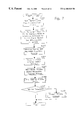
- FIG. 6A is a part of flow chart of the main routine of the camera shown in FIG. 1;
- FIG. 6B is a part of flow chart of the main routine of the camera shown in FIG. 1;
- FIG. 7 is a flow chart of the release process of the camera shown in FIG. 1;
- FIG. 8 is a flow chart of a sub-routine in which parameters are written in an EEPROM immediately after the winding operation, of the flow chart shown in FIG. 7, to move the film on one frame is completed;
- FIG. 9 is a flow chart of a sub-routine of the flow chart shown in FIG. 8;
- FIG. 10 is a flow chart of a sub-routine of the flow chart shown in FIG. 8;
- FIG. 11 is a flow chart of a sub routine of the flow chart shown in FIG. 8;
- FIG. 12 is a flow chart of a sub-routine of the flow chart shown in FIG. 8;
- FIG. 13 is a flow chart of the rewinding process of the camera shown in FIG. 1 in which the data imprinting process is performed;
- FIG. 14 is a flow chart of a sub-routine of the flow chart shown in FIG. 13;
- FIG. 15 is a flow chart of the data imprinting process shown in FIG. 13;
- FIG. 16 is a flow chart of the first-timer interruption process
- FIG. 17 is a flow chart of the second-timer interruption process
- FIG. 18 is a flow chart of the imprinting data conversion/setting process of the flow chart shown in FIG. 15;
- FIG. 19 is a time chart showing a correlation between sprocket holes of film and each film pulse in the camera to which the present invention is applied;
- FIG. 20 is an enlarged view of part of the time chart shown in FIG. 19.
- FIGS. 21A and 21B are plan view of part of a roll film on which photographic data are imprinted by the data imprinting device of the camera to which the present invention is applied.
- FIG. 1 shows an embodiment of an SLR camera with the hack lid thereof open.
- the SLR camera is provided with an electronic control circuit which controls the exposure operation, the shutter release operation and other operations of the camera.
- the SLR camera is provided with a data imprinting device which is composed of an LED character generator 11 and a light guide optical system 12 .
- the data imprinting device is mounted on the back lid 13 (see FIG. 2) which is rotatably connected to a camera body 21 , the data imprinting device is shown in FIG. 1 for the purpose of illustration.
- FIG. 2 is a cross sectional view of the camera, taken along the I—I line, viewed in the direction of the appended arrows.
- the camera body 21 is provided at the left and right ends thereof with a film chamber 32 and a spool chamber 33 , respectively, as viewed in FIG. 1.
- a film cartridge FC shown by a one-dot chain line in FIG. 2, is loaded in the film chamber 32 , while a film take-up spool 24 is positioned in the spool chamber 33 .
- the camera is provided in the film chamber 32 with a rewind is shaft 22 and DX-information pins 26 .
- the total number of DX-information pins 26 are nine; the right row includes six pins and the left row includes three pins as viewed in FIG. 1.
- a sprocket 25 which is engaged with sprocket holes of a film (roll film) 14 to detect the movement of the sprocket holes is positioned on the immediate left side of the spool chamber 33 as viewed in FIG. 1, so that the upper and lower ends of the sprocket 25 are rotatably held by the camera body 21 .
- the camera is provided between the film chamber 32 and the spool chamber 33 with a shutter unit 16 (see FIG. 2 ).
- the camera is further provided, in the back of the camera body 21 at a lower center thereof, with an array of contacts 23 .
- the back lid 13 is provided with a corresponding array of pins 20 (only one of them is shown in FIG. 3) which are brought into contact with the array of contacts 23 upon the back lid 13 being closed. Electrical signals can be sent from the camera body 21 to the back lid 13 and vice versa via the array of contacts 23 and the array of pins 20 .
- FIG. 3 shows a cross sectional view of part of the camera with the back lid 13 being closed, viewed from the left side of the camera as viewed in FIG. 1 .
- the back lid 13 is provided with a pressure plate 17 which maintains the flatness of the film 14 , and a base plate 18 .
- the back lid 13 is further provided between the base plate 18 and the back lid 13 with the LED character generator 11 and the light-guide optical system 12 , which are fundamental elements of the data imprinting device.
- the character generator 11 is provided with an LED light emitter having multiple-dots (e.g. 7 dots) aligned vertically to emit light in accordance with character information.
- the light-guide optical system 12 leads the light emitted by the character generator 11 to a character imprinting portion 12 a (the exit surface of the light-guide optical system 12 ).
- the light-guide optical system 12 is provided with a plurality of reflecting surfaces which change the arrangement of the array of multiple-dots to in appropriate arrangement at an imprinting position on the film 14 .
- a tiny window or opening (see FIG. 3) 17 a is formed on the pressure plate 17 at a position opposed to an upper inner film guide rail 9 b formed on an aperture frame 9 having a rectangular photographic aperture 9 a.
- the upper inner film guide rail 9 b is formed on the aperture frame 9 so that the sprocket holes formed on the upper side of the film 14 therealong as viewed in FIG. 1 travel on the upper inner film guide rail 9 b.
- the character imprinting portion 12 a of the light-guide optical system 12 is positioned behind the tiny window 17 a.
- the character generator 11 emits light to be projected towards the film 14 between two adjacent sprocket holes to be exposed thereon in accordance with character information output from a CPU 34 (see FIG. 5 ).
- the emitted light carries a certain image of a pattern of characters and is incident on the back of the film 14 via the light-guide optical system 12 and the tiny window 17 a to thereby imprint the photographic data on the film 14 as a latent image.
- the back lid 13 is provided in a lower portion thereof with the aforementioned array of pins 20 .
- the pins 20 are electrically connected with the character generator 11 via a flexible wiring board 19 (see FIG. 3) so that electrical signals can be sent from the camera body 21 to the character generator 11 via the flexible wiring board 19 , the array of pins 20 and the array of contacts 23 .
- the sprocket 25 is provided around the lower end thereof with four projections 30 which extend radially and outwardly at regular intervals. At least one of the four projections 30 is engaged with any sprocket hole of the film 14 (see FIG. 2) at a time, so that the sprocket 25 rotates while the film 14 is wound or rewound.
- the sprocket 25 is provided at one end thereof with a gear 25 a which is in constant mesh with a gear 31 to which a brush 29 is fixed.
- the brush 29 is positioned on a detector board 28 to contact a predetermined code pattern printed thereon. Therefore, rotation of the sprocket 25 causes the brush 29 to rotate and slide on the code pattern of the detector board 28 .
- the sprocket 25 With this mechanism, rotation of the sprocket 25 is detected.
- the sprocket 25 , the projections 30 , the gear 31 , the detector board 28 , the brush 29 , and the CPU 34 constitute a film moving detector.
- the brush 29 rotates by a predetermined angle of rotation, two output terminals 28 a and 28 b on the detector board 28 are electrically connected and disconnected alternately.
- One of the output terminals 28 a and 28 b is grounded, so that the level of the signal output from the other output terminal alternately changes between a high level and a low level; this electric device is hereinafter referred to as film switch 58 (see FIG. 5 ).
- the CPU 34 (which functions as a film speed detecting device) detects the variation in level of the signal output from the other output terminal 28 a or 28 b as pulses (film pulses) generated by the movement of the film 14 .
- the last frame of the film 14 when fully wound is shown in FIG. 19, as viewed from the underside of the film 14 .
- the film can only be wound out by an amount less than one frame wherein the end portion of the film 14 has been reached, so that no more film can be drawn out from the cartridge FC.
- the film 14 reaches the end portion thereof upon the film 14 being completely wound, and the last frame of the film 14 becomes the last photographic frame.
- the last photographic frame is referred to as the final frame, and the number of sprocket holes of the end portion of the film 14 detected from the final frame until the completion of winding of the film 14 is equivalent to the amount of movement of the film 14 from the edge of the photographic frame to the final edge of the film 14 .
- FIG. 19 shows a time chart illustrating a correlation between the sprocket holes of the film 14 and each film pulse, in the case of imprinting photographic data on the film 14 between two adjacent sprocket holes thereof upon the film 14 being rewound.
- the horizontal axis of the time chart represents time.
- Each film frame FF has eight consecutive sprocket holes on each side of the film 14 (see FIG. 21 ). Therefore, since photographic data can be imprinted on the film 14 between any two adjacent sprocket holes, there are technically seven areas available for photographic data to be imprinted therein for each film frame FF.
- the 19 is a low-level/high-level pulse signal which is generated by the film switch 58 when the two output terminals 28 a and 28 b thereof are electrically connected and disconnected.
- the level of the film switch signal varies each time an edge of each sprocket hole passes a predetermined position.
- the CPU 34 (which function as a common detecting device including the function of a sprocket-hole detecting device and the function of the above-mentioned film speed detecting device) detects which edge of the sprocket holes of the film 14 has passed the predetermined position by detecting the variation of the level of the film switch signal to thereby detect the positions of consecutive sprocket holes.
- the data imprinting device starts imprinting photographic data from a position determined in accordance with the positions of the sprocket holes.
- each reference letter “A” represents the duration of the high level of a film pulse
- each reference letter “B” represents the duration of the low level
- each reference numeral “E” represents the time necessary for photographic data to be imprinted between two adjacent sprocket holes.
- a first delay time “C” necessary for converting four characters which are to be imprinted between two adjacent sprocket holes of the film 14 into photographic data and also a second delay time “D” which is calculated in accordance with the speed of movement of the film 14 are utilized.
- FIG. 20 is an enlarged view of part of the time chart shown in FIG. 19 .
- the data imprinting operation includes an imprinting function wherein, in order to imprint each character formed by a matrix of seven dots by five dots (the matrix constituting one unit of data), the five columns of the matrix (each of which is formed by seven dots), are intermittently imprinted column by column on the film 14 between two adjacent sprocket holes thereof by controlling the character generator 11 to emit light for each column by a data imprinting time (light-emission duration) “G” determined in accordance with the ISO speed information of the film 14 per cycle (data imprinting period) “F” of the pulse signals determined by calculation in accordance with the detected speed of movement of the film 14 .
- a data imprinting time light-emission duration
- FIGS. 21A and 21B show part of the film 14 on which different photographic data (Time Value TV, Aperture Value AV, Exposure Compensation Value XV, Exposure Mode and Film number) are imprinted for each film frame by the data imprinting device of the present embodiment of the camera.
- FIG. 5 is a block diagram of a control circuit of the present embodiment of the SLR camera.
- the control circuit is provided with the CPU 34 including ROMs and RAMs therein.
- the control circuit is further provided with a DC/DC converter 35 , a voltage regulator 36 , a motor driver IC 38 , a mirror drive motor 39 , a motor driver IC 40 , a film winding/rewinding motor 41 , a shutter control circuit 42 , a diaphragm control circuit 43 , a clock generator 44 , a clock IC 45 , a photometer IC 46 , an AVVR (Aperture Value Variable Resistor) 47 , a viewfinder internal LCD 48 , an LED 49 , an external LCD 50 , an EEPROM (non-volatile memory) 51 , a data imprinting circuit 52 , a DX code identifying circuit 53 , and various switches which are all connected to the CPU 34 .
- AVVR Absolute Value Variable Resistor
- the film take-up spool 24 , the rewind shaft 22 , the CPu 34 , the motor driver IC 40 and the film motor 41 constitute a motorized film transport device.
- the camera is provided in the camera body 21 with a quick-return mirror (not shown) which reflects light passed through the photographic optical system (interchangeable lens) towards the finder optical system immediately before a shutter release.
- a battery 37 as power supply which is accommodated in a battery chamber of the camera, is connected to the CPU 34 via the DC/DC converter 35 and the voltage regulator 36 .
- the mirror drive motor 39 and the film winding/rewinding motor 41 which function as drive devices are connected to the CPU 34 via the motor drivers IC 38 and 40 , respectively.
- the shutter control circuit 42 , the diaphragm control circuit 43 , the data imprinting circuit 52 and the DX code identifying circuit 53 which function as circuit devices are connected to the CPU 34 .
- the data imprinting circuit 52 controls the operation of imprinting photographic data between two adjacent sprocket holes of the film 14 .
- the DX code identifying circuit 53 identifies a DX code printed on the film cartridge FC via the DX-information pins 26 .
- the photometer IC 46 and the AVVR 47 which function as sensor devices are connected to the CPU 34 .
- the photometer IC 46 is used for the automatic exposure control of the camera while the AVVR 47 is used to detect the size of the diaphragm.
- the viewfinder internal LCD 48 indicates various photographic information in the field of view of the viewfinder.
- the LED 49 illuminates the LCD 48 .
- the external LCD 50 indicates various photographic information such as the selected photographic mode and film information (the number o)f remaining frames, ISO speed information, etc.) at an appropriate position
- a main switch 61 functions as the power switch for the camera.
- a photometering switch SWS which is turned ON upon the release button of the camera being half depressed, a release switch SWR which is turned ON upon the release button of the camera being fully depressed, the aforementioned film switch 58 for generating film pulses by movement of the film 14 , and a data-imprinting permission switch 54 which turns the emission of the character generator 11 ON and OFF are connected to the CPU 34 .
- a back-lid switch 60 for detecting whether the back lid 13 is open or closed, a mirror-up switch 56 for detecting whether the quick-return mirror is positioned at the upper end position (raised position) thereof, a mirror-down switch 55 for detecting whether the quick-return mirror is positioned at the lower end position (initial position) thereof, a mid-roll rewind switch 59 , a film cartridge switch 57 for detecting whether the film cartridge FC in is the film chamber 32 , are also connected to the CPU 34 .
- the EEPROM (memory) 51 stores various photographic data and parameters.
- the clock generator 44 generates drive clock pulses for the CPU 34 .
- the clock IC 45 counts the time and date.
- the present embodiment of the camera operates according to a control program in the following manner. Firstly, each time the shutter is released, photographic data (Time Value TV, Aperture Value AV, Exposure Compensation Value XV, Exposure Mode and Film number) on each frame are written into the EEPROM 51 immediately before the shutter is released. After all the frames are exposed, the number of edges of the film pulses generated by the last inch of the film 14 which extends from the trailing edge of the last frame to the film end is written into the EEPROM 51 .
- photographic data Time Value TV, Aperture Value AV, Exposure Compensation Value XV, Exposure Mode and Film number
- the film take-up spool 24 locks up when the film end reaches the sprocket 25 , i.e., when the sprocket hole at the film end is engaged with any one of the four projections 30 of the sprocket 25 .
- the end of the film 14 is defined by the position of the sprocket 25 provided in the camera body 21 in the present embodiment.
- the sprocket 25 , the projections 30 , the gear 31 , the detector board 28 , the brush 29 , and the CPU 34 constitute a frame edge detector.
- the CPU 34 controls the data imprinting device so that it does not imprint any photographic data on film in the last inch of the film 14 which extends from the trailing edge of the last frame to the film end. Namely, after the rewinding operation starts, the CPU 34 starts counting the edges of the film pulses and frames upon detecting the trailing edge of the last frame to start imprinting corresponding photographic data on respective exposed frames precisely at predetermined areas thereof.
- Control of the camera of the present embodiment will be hereinafter discussed with reference to FIGS. 6A and 6B, which shows a flow chart of the main routine of the camera.
- the CPU 34 performs all the operations and processes contained in the main routine shown in FIG. 6 A. Control enters the main routine immediately after the battery 37 is loaded is in the camera. At first, the CPU 34 and peripheral circuits are initialized (steps S 101 and S 102 ). Subsequently, data stored in the EEPROM 51 is read out to be input to the internal RAM of the CPU 34 (step S 103 ), and the DC/DC converter 35 is turned OFF (step S 104 ) Thereafter, the ON/OFF states of all the switches are input to the CPU 34 (step S 105 ).
- step S 106 it is determined whether the main switch 61 is ON. If it is determined that the main switch 61 is not ON, data of the ON/OFF states of all the switches is processed to be indicated on the external LCD panel 50 (steps S 107 and S 108 ). Subsequently, interruption of the main switch 61 is permitted (step S 109 ), and the camera falls into a low-power consumption mode, i.e., a sleep mode (step S 110 ). The camera returns to a normal mode immediately after the main switch 61 is turned ON (step S 111 ). Thereafter, an interruption of the main switch 61 is prohibited (step S 112 ), control returns to step S 105 , and the operations from step S 105 to step S 112 are repeated.
- step S 112 interruption of the main switch 61 is prohibited
- step S 106 If it is determined at step S 106 that the main switch 61 is ON, a 250 ms timer in the CPU 34 starts, in preparation for the photographing process (step S 113 ). Subsequently, data of the ON/OFF states of all the switches which are input to the CPU 34 at step S 105 is processed to be indicated on the external LCD panel 50 (steps S 114 and S 115 ). Subsequently, it is determined whether the mid-roll rewind switch 59 is ON (step S 116 ). If it is determined that the mid-roll rewind switch 59 is ON, this indicates that the mid-roll rewind switch 59 has been depressed, so that the rewind process is performed (step S 117 ).
- step S 116 If it is determined at step S 116 that the mid-roll rewind switch 59 is OFF, it is determined whether the state of the back lid 13 has changed from a closed state to an open state (step S 118 ). If it is determined that the state of the back lid 13 has changed from a closed state to an open state, the back-lid-open process is performed (step S 119 ) and subsequently control returns to step S 105 .
- step S 120 it is determined whether the state of the back lid 13 has changed from an open state to a closed state. If it is determined that the state of the back lid 13 has changed from an open state to a closed state, indicating that the film cartridge FC may have been loaded into the camera, the loading process is performed (step S 121 ) and subsequently control returns to step S 105 . If the back lid 13 remains closed, it is determined whether either the photometering switch SWS or the release switch SWR is ON, i.e., whether the release button is in the state of being half or fully depressed (step S 122 ).
- step S 123 If neither switch SWS nor SWR is ON, interruption of the timer is permitted (step S 123 ), and the camera falls into the low-power consumption mode, i.e., the sleep mode (step S 124 ). Thereafter, the camera returns to the normal mode immediately after the 250 ms timer elapses (step S 124 ). Thereafter, interruption of the timer is prohibited (step S 126 ), and control returns to step S 105 .
- step S 122 If it is determined at step S 122 that either the photometering switch SWS or the release switch SWR is ON, i.e., the release button is in the state of being at least half depressed, the DC/DC converter 35 is turned ON in preparation for the release process of step S 142 (step S 127 ). Subsequently, the initial number of a power-hold counter in the CPU 34 is set to 80 (step S 128 ), and a 125 ms interval timer in the CPU 34 starts (step S 129 ).
- the ON/OFF states of all the switches are input to the CPU 34 (step S 130 ).
- it is determined whether the main switch 61 is OFF (step S 131 ). If it is determined at step S 131 that the main switch 61 is OFF, it is no longer necessary for the camera to be held in the normal mode, therefore control returns to step S 104 .
- step S 132 it is determined whether the mid-roll rewind switch 59 is ON. If it is determined that the mid-roll rewind switch 59 is ON, control returns to step S 104 in order to perform the rewind operation at step S 117 . If it is determined at step S 132 that the mid roll rewind switch 59 is not ON, it is determined whether the state of the back lid 13 has changed from a closed state to an open state (step S 133 ). If it is determined that the state of the back lid 13 has changed from a closed state to an open state, control returns to step S 104 to perform the back-lid-open process at step S 119 .
- step S 134 it is determined whether the state of the back lid 13 has changed from an open state to a closed state. If it is determined at step S 134 that the state of the back lid 13 has changed from an open state to a closed state, control returns to step S 104 to perform the loading process at step S 121 . If the back lid 13 remains closed, data which varies due to the variation of the ON/OFF state of each switch is renewed (step S 135 ). Subsequently, the photometering operation is performed (step S 136 ), and the indicating process for indicating various photographic data on each of the internal and external LCDs 48 and 50 is performed (step S 137 ).
- step S 138 it is determined whether the release switch SWR is ON (step S 138 ), and the release process is performed (step S 142 ) if the release switch SWR is ON. If it is determined at step S 138 that the release switch SWR is not ON, it is determined whether the 125 ms of the 125 ms interval timer has elapsed (step S 139 ). The operation at step S 139 is repeated until the 125 ms elapses. Immediately after the 125 ms has elapsed, it is determined whether the value of the power-hold timer is zero (step S 140 ).
- step S 141 If the value of the power-hold timer is not zero, the number is decreased by one (step S 141 ), and control returns to step S 130 so that the operations from step S 130 to step S 141 are repeated until the value of the power-hold timer is zero. If it is determined at step S 140 that the value of the power-hold timer is zero, it is determined whether either the photometering switch SWS or the release switch SWR is ON (step S 143 ). If either switch SWS or SWR is ON, indicating that the release button is still in the state of being at least half depressed, control returns to step S 130 in preparation for the release process of step S 142 . If neither switch SWS nor SWR is ON, control returns to step S 104 .
- step S 142 The release process performed at step S 142 will be hereinafter discussed with reference to FIG. 7 which shows a flow chart thereof.
- the exposure process in which the diaphragm and the quick-return mirror are actuated, is performed immediately after the release switch is fully depressed.
- the release process firstly the final photometering process and the indicating process are performed before the shutter is released (step S 201 ).
- photographic data (Time Value TV, Aperture Value AV, Exposure Compensation Value XV and Exposure Mode) are stored in respective addresses for the current Film number in the EEPROM 51 (step S 202 ).
- the mirror-up process, the diaphragm stop-down process, the exposure process (shutter control process), the mirror-down process and the shutter-mechanism charging process are performed (steps S 203 , S 204 and S 205 ).
- the film winding process is performed (step S 206 ).
- it is determined whether the film end is detected is determined whether the film end is detected (step S 207 ). If the film end is detected, the rewind process is performed (step S 208 ) and control returns, otherwise the rewind process is not performed and control returns.
- FIG. 8 shows a flow chart of the process at step S 206 shown in FIG. 7 .
- firstly all the variables used in the rewinding process are initialized (step S 301 ).
- variables “wind_time_out”, “film_wind_status”, “film_brake_counter”, “F_FILM_WIND_END”, “low_edge_width_time”, “high_edge_width_time” and “edge_counter” are all set to 0, and variable “edge_width_time” is set to ⁇ 1, and the state of the film switch 58 is stored in the internal RAM of the CPU 34 (step S 401 ).
- a loading-completion flag (F_LOAD_OK) is 0 (step S 402 ). If the loading-completion flag (F_LOAD_OK) is not 0, indicating that the film cartridge FC has been loaded in the camera, control returns. If it is determined at step S 402 that the loading-completion flag (F_LOAD_OK) is 0, indicating that a film cartridge FC is not loaded in the camera, the film-winding completion flag (F_FILM_WIND END) is set to 1 (step S 403 ) and control returns because it is not necessary to rewind the film 14 .
- a 100 ⁇ s-interval timer in the CPU 34 starts (step S 302 ). Subsequently, it is determined whether the micror-down process has completed (i.e., whether the flag (F_MIRROR_DOWN_END) is 1) (step S 303 ). If it is determined that the mirror-down process has not yet completed (i.e., the flag (F_MIRROR_DOWN_END) is not 1), the mirror-down process is performed (step S 304 ) and subsequently it is determined whether the flag (F_FILM_WIND_END) is 1 (step S 305 ).
- Step S 312 is repeated until 100 ⁇ s has elapsed thereat. If it is determined at step S 312 that 100 ⁇ s has elapsed, control returns to step S 303 .
- the 100 ⁇ s-interval timer defines the period of repeating the operations from step S 303 to step S 312 .
- step S 303 If it is determined at step S 303 that the mirror down process has completed (i.e., the flag (F_MIRROR_DOWN_END) is 1), it is determined whether the film-winding completion flag (F_FILM_WIND_END) is 1 (step S 306 ). If the film-winding completion flag (F_FILM_WIND_END) is 1, parameters at this moment (the details of these parameters will be discussed hereinafter) are written into the EEPROM 51 (step S 313 ) and control returns. If the film-winding completion flag (F_FILM_WIND_END) is riot 1, the leading and trailing edges (designated by the reference numerals 1 through 16 for each frame as shown in FIG.
- step S 307 it is determined whether the number of an edge-width measuring counter (edge_width_time) in the CPU 34 that is used for measuring a half of the period of the film pulse is equal to or over 4,000, i.e., whether 400 ms has elapsed since the aforementioned 100 ⁇ s-interval timer started (step S 308 ).
- edge_width_time an edge-width measuring counter
- edge_width_time the number of the edge-width measuring counter (edge_width_time) increases by one each time 100 ⁇ s elapses as long as the state of the film pulse does not vary from the previous state thereof
- the number “4,000” of the edge-width measuring counter (edge_width_time) corresponds to a lapse of 400 ms. Therefore, it is determined at step S 308 whether 400 ms has elapsed since the aforementioned 100 ⁇ s-interval timer started.
- step 5308 If it is determined at step 5308 that the number of the edge-width measuring counter (edge_width_time) is equal to or over 4,000, indicating that the film 14 is not in motion, the CPU 34 judges that the film 14 has reached the end, upon winding thereof (i.e., the film end has reached the sprocket 25 ), and thus the wind-time-out flag (wind_time_out) which indicates the time-out on film wending is set to 1 (step S 309 ). Subsequently the film winding process is performed (step S 310 ).
- edge_width_time the number of the edge-width measuring counter
- step S 308 If it is determined at step S 308 that the number of the edge-width measuring counter (edge_width_time) is less than 4,000, the operation at step S 309 is skipped and subsequently the film winding process is performed (step S 310 ). Subsequently, a character or characters showing the number of film frame and/or a character having the shape of a film cartridge FC are indicated on the external LCD 50 to inform the user that the film 14 is now being wound (step S 311 ). Subsequently, it is determined whether 100 ⁇ s has elapsed (step S 312 ). The operation at step S 312 is repeated until 100 ⁇ s has elapsed thereat. If it is determined at step S 312 that 100 ⁇ s has elapsed, control returns to step S 303 , so that the operations from step S 303 to step S 312 are repeated.
- edge_width_time the number of the edge-width measuring counter
- step S 307 in which the leading and trailing edges of the film pulses generated by the variation in the state of the film switch 58 are counted will be hereinafter discussed with reference to FIG. 10 .
- the state of the film pulse i.e, whether the level of the film pulse is low or high
- the pulse-width measuring counter (edge_width_time)
- the pulse-width measuring counter (edge_width_time) is increased by one (step S 501 ).
- the previous state (low level or high level) of the film pulse is stored (e.g., in a register), and the current state of the film pulse is read out to be stored (e.g., in a register) (steps S 502 and S 503 ).
- step S 506 If it is detected at step S 505 that the level of the previous film pulse is low, indicating that the leading edge of film pulse has been detected, the value of the pulse-width measuring counter (edge_width_time) at this moment is stored as a low-pulse width or low-pulse duration (low_edge_width_time) (step S 506 ). Namely, a period of time corresponding to the low-pulse width (low_edge_width_time) corresponds a period of time of the low-level film pulse.
- an edge counter for counting the leading and trailing edges of the film pulses in the direction of winding the film 14 is increased by 1 (step S 509 )
- the pulse-width measuring counter (edge_width_time) is set to 0 (step S 510 ) and control returns. If it is detected at step S 504 that the level of the current film pulse is not high, it is determined whether the level of the previous film pulse is high (step S 507 ). If the level of the previous film pulse is not high, indicating that the level of the film pulse remains low, control returns.
- the pulse width measuring counter (edge_width_time) at this moment is stored as a high-pulse width or high-pulse duration (high_edge_width time) (step S 508 ) and subsequently control proceeds to the operation at step SS 09 .
- the film winding process at step S 310 will be hereinafter discussed with reference to FIG. 11 .
- the sub-routine shown in FIG. 11 controls the film winding/rewinding motor 41 from the commencement time to the completion time of winding the film 14 .
- the film-wind-control-status counter (film_wind_status) represents the step in control of the winding process and indicates that the film winding/rewinding motor 41 is still in operation if the number of the counter is less than 5.
- step S 1301 If it is determined at step S 1301 that the wind-time-out flag (wind_time_out) is not 1 or if it is determined at step S 1302 that the film-wind-control-status counter (film_wind_status) is not less than 5, the film-wind-control-status counter (film_wind_status) is checked (step S 1306 ). If the film-wind-control-status counter (film_wind_status) is 0, the film winding/rewinding motor 41 is driven forward to wind the film 14 (step S 1307 ) and subsequently the film-wind-control-status counter (film_wind_status) is set to 1 (step S 1308 ). Subsequently control returns.
- step S 1309 If the film-wind-control-status counter (film_wind_status) is 1, it is determined whether the edge counter (edge_counter) is 15 (step S 1309 ). Control returns if the counter (edge_counter) is not 15, so that the operations from step S 303 to S 312 are repeated until the edge counter (edge counter) reaches 15.
- step S 1309 If it is determined at step S 1309 that the edge counter (edge_counter) is 15, indicating that the film winding by one frame is almost completed, the film winding/rewinding motor 41 is braked via short-circuiting, the film brake counter (film_brake_counter) is set to 100, and the film-wind-control-status counter (film_wind_status) is set to 2 (steps S 1310 , S 1311 and S 1312 ). Subsequently, control returns.
- step S 1314 If the film-wind-control-status counter (film_wind_status) is 2, the film brake counter (film_brake_counter) is decreased by one (step S 1313 ), and subsequently it is determined whether the film brake counter (film_brake_counter) is 0 (step S 1314 ). If the film brake counter (film_brake_counter) is not 0 (Step S 1314 ), control proceeds to step S 1317 . If it is determined at step S 1314 that the film brake counter (film_brake_counter) is 0, the film winding/rewinding motor 41 is driven forward to wind the film 14 (step S 1315 ) and subsequently the film-wind-control-status counter (film_wind_status) is set to 3 (step S 1316 ). Subsequently control proceeds to the operation at step S 1317 .
- step S 1306 If it is determined at step S 1306 that the film-wind-control-status counter (film_wind_status) is 3, it is determined whether the edge counter (edge_counter) is 16 (step S 1317 ). Control returns if the counter (edge_counter) is not 16, so that the operations from step S 303 to S 312 are repeated until the edge counter (edge_counter) reaches 16.
- step S 1317 If it is determined at step S 1317 that the edge counter (edge_counter) is 16, so that the film winding/rewinding motor 41 is braked by reversing the driving direction thereof, the film brake counter (film_brake_counter) is set to 100, and the film-wind-control-status counter (film_wind_status) is set to 4 (steps S 1318 , S 1319 and S 1320 ). Subsequently, control returns.
- step S 1321 If the film-wind-control-status counter (film_wind_status) is 4, the film brake counter (film_brake_counter) is decreased by one (step S 1321 ), and subsequently it is determined whether the film brake counter (film_brake_counter) is 0 (step S 1322 ). Control returns if the film brake counter (film brake_counter) is not 0, so that the operations from step S 303 to S 312 are repeated until the film brake counter (film_brake_counter) becomes 0.
- step S 1322 If it is determined at step S 1322 that the film brake counter (film_brake_counter) is 0, the film winding/rewinding motor 41 is braked via short-circuiting, the film brake counter (film_brake_counter) is set to 100, and the film-wind-control-status counter (film_wind_status) is set to 5 (steps S 1323 , S 1324 and S 1325 ). Subsequently, control returns.
- step S 1326 If the film-wind-control status counter (film_wind_status) is 5, the film brake counter (film_brake_counter) is decreased by one (step S 1326 ), and subsequently it is determined whether the film brake counter (film_brake_counter) is 0 (step S 1327 ). Control returns if the film brake counter (film_brake_counter) is not 0, so that the operations from step S 303 to S 312 are repeated until the film brake counter (film_brake_counter) becomes 0.
- step S 1327 If it is determined at step S 1327 that the film brake counter (film_brake_counter) is 0, the film winding/rewinding motor 41 is freed, and the film-wind-control-status counter (film wind_status) is set to 6, and the film-winding completion flag (F_FILM_WIND_END) is set to 1 (steps S 1328 , S 1329 and S 1330 ). Subsequently control returns.
- step S 313 it is determined whether the loading-completion flag (F_LOAD_OK) is 1, i.e., whether the film has been loaded (step S 601 ). If the loading-completion flag (F_LOAD_OK) is not 1, indicating that a film cartridge is not loaded in the camera, control returns. If the loading-completion flag (F_LOAD_OK) is 1, the film cartridge FC has been loaded in the camera, and it is determined whether the wind-time-out flag (wind_time_out) is 0 (step S 602 ).
- a film-frame-number counter (ee_film_counter) is increased by one and the number thereof is written into the EEPROM 51 (step S 603 ). If the wind-time-out flag (wind_time_out) is not 0, indicating that the winding of the film 14 has reached the film end, a film-end-edge number (ee_film_end_edge), which indicates the number of edges of the film pulses generated by the last inch of the film 14 from the trailing edge of the last frame to the film end, is written into the EEPROM 51 as the numerical value of the edge counter (edge_counter) at this moment (step S 604 ).
- the trailing edge of the last frame can be detected in accordance with the film-end edge number (ee_film_end_edge) stored in the EEPROM 51 .
- a film end flag (F_FILM_END) is set to 0 and written into in the EEPROM 51 (step S 605 ). Thereafter control returns.
- step S 117 and S 208 The rewind process performed at steps S 117 and S 208 will be hereinafter discussed with reference to FIG. 13 which shows a flow chart thereof.
- the film winding/rewinding motor 41 is driven to reverse the drive shaft thereof to rewind the film 14 (step S 702 ), and a 100 ⁇ s interval timer in the CPU 34 starts (step S 703 ).
- the 100 ⁇ s interval timer defines the period for repeating the operations from step S 704 to step S 708 .
- step S 704 the leading and trailing edges (designated by the reference numerals 1 through 16 for each frame as shown in FIG. 19) of the film pulses generated by the movement of the film 14 are counted.
- step S 705 the data imprinting process is performed (step S 705 ), and a character or characters showing the number of film frame and/or a character having the shape of a film cartridge FC are indicated on the external LCD 50 to inform the user that the film 14 is now being rewound (step S 706 ).
- step S 707 it is determined whether the total counted number of a pulse-width measuring counter (edge_width_time) in the CPU 34 that is used for measuring a half of the period of the film pulse is over 16,000, i.e., whether 1.6 seconds has elapsed since the aforementioned 100 ⁇ s interval timer started (step S 707 ). If it is determined at step S 707 that 1.6 seconds has not yet elapsed, it is determined whether 100 ⁇ s has elapsed (step S 708 ). The operation at step S 708 is repeated until 100 ⁇ s has elapsed thereat. If it is determined at step S 708 that 100 ⁇ s has elapsed, control returns to step S 704 .
- edge_width_time the total counted number of a pulse-width measuring counter
- step S 704 to S 708 are repeated until it is determined at step S 707 that 1.6 seconds has elapsed since the aforementioned 100 ⁇ s interval timer started.
- the number of the pulse-width measuring counter (edge_width_time) increases by one every time 100 ⁇ s elapses.
- step S 707 If it is determined at step S 707 that 1.6 seconds has elapsed without any variation of the film pulses level, indicating that the film 14 has been completely rewound, the power supply to the film winding/rewinding motor 41 is stopped in order to stop the film winding/rewinding motor 41 (step S 709 ), and the film winding/rewinding motor 41 is freed from control (step S 710 ). Subsequently, it is determined whether a normal-loading completion flag (F_LOAD_OK) is 1 (step S 711 ).
- F_LOAD_OK normal-loading completion flag
- step S 712 If the normal-loading completion flag (F_LOAD_OK) is 1, indicating that the film cartridge FC has been loaded in the camera, a serial number (ee_film_no) which shows the serial number of the film cartridge FC is increased by one and stored the EEPROM 51 (step S 712 ). If it is determined at step S 711 that the normal-loading completion flag (F_LOAD_OK) is not 1, control skips the operation at step S 712 .
- a film-end-edge counter (ee_film_end_edge), which indicates the number of edges of the film pulses generated within the last inch of the film 14 from the trailing edge of the last frame to the film end, and a film-frame-number counter (ee_film_counter) are each set to 0 and these values are stored in the EEPROM 51 (steps S 713 and S 714 ). Subsequently, the normal-loading completion flag (F_LOAD_OK), a film end flag (F_FILM_END) and a rewind end flag (F_REW_END) are set to 0, 0 and 1, respectively, and are stored in the EEPROM 51 (step S 715 ). Thereafter control returns.
- F_LOAD_OK normal-loading completion flag
- F_FILM_END film end flag
- F_REW_END rewind end flag
- step S 704 in which the leading and trailing edges of the film pulses generated by the movement of the film 14 are counted will be hereinafter discussed with reference to FIG. 14 .
- the state of the film pulse i.e., whether the level of the film pulse is low or high
- the pulse-width measuring counter (edge_width_time)
- the pulse-width measuring counter (edge_width_time) is increased by one (step S 801 ).
- the previous state (low level or high level) of the film pulse is stored (e.g., in a register), and the current state of the film pulse is read out to be stored (e.g. in a register) (steps S 802 and S 803 ).
- step S 805 If it is detected at step S 805 that the level of the previous film pulse is low, indicating that the leading edge of film pulse has been detected, so that the value of the pulse-width measuring counter (edge_width_time) at this moment is stored as a low-pulse width or low pulse duration (low_edge_width_time) (step S 806 ). Namely, a period of time corresponding to the low-pulse width (low_edge_width_time) corresponds a period of time of the low-level film pulse. Subsequently, the pulse-width measuring counter (edge_width_time) is set to 0 in order to measure a half of the period of the subsequent film pulse (step S 809 ).
- step S 810 it is determined whether the film-end-edge number (ee_film_end_edge) is 0 (step S 810 ). If it is determined that the film_end_edge number (ee_film_end_edge) is not 0, indicating that the trailing edge of the last frame has not been detected, so that the film-end-edge number (ee_film_end_edge) is decreased by 1 (step S 812 ) for the subsequent edge of the film pulse, and control returns.
- an edge counter for counting the leading and trailing edges of the film pulses in the direction of rewinding the film 14 is increased by 1 to start counting the edges of the film pulses from the trailing edge of the last frame. (step S 811 ). Subsequently, it is determined whether the edge counter (edge_counter) is 16 (step S 813 ). If the edge counter (edge_counter) is not 16 , control returns.
- edge counter (edge_counter) is 16 , indicating that eight sprocket holes for one film frame has passed
- the edge counter (edge_counter) is set to 0 to start counting the leading and trailing edges of the film pulses generated by the sprocket holes of the subsequent film frame (step S 814 ).
- the film-frame-number counter (ee_film_counter) is decreased by 1 (step S 815 ), and control returns.
- step S 807 If it is detected at step S 804 that the level of the current film pulse is not high, it is determined whether the level of the previous film pulse is high (step S 807 ). If the level of the previous film pulse is not high, indicating that the level of the film pulse remains to be low, control returns Tf the level of the previous film pulse is high, indicating that the trailing edge of film pulse has been detected, the pulse-width measuring counter (edge_width_time) at this moment is stored as a high-pulse width or high-pulse duration (high_edge_width_time) (step S 808 ) and subsequently control proceeds to the operation at step S 809 .
- edge_width_time the pulse-width measuring counter
- FIG. 15 shows a flow chart of the data imprinting process.
- the data imprinting operation in which photographic data is imprinted on the film 14 , is permitted by checking the ON/OFF state of the data-imprinting permission switch 54 (step S 901 ). If it is determined that the data imprinting operation is not permitted, it is not necessary to imprint any data on the film 14 , and control returns. If it is determined that the data imprinting operation is permitted, it is determined whether the film-frame-number counter (ee_film_counter) is 1 or more (step S 902 ).
- the film-frame-number counter ee_film_counter
- step S 903 If the film-frame-number counter (ee_film_counter) is less than 1, control returns. If the film-frame-number counter (ee_film_counter) is 1 or more, it is determined whether the data-imprinting-start flag (F_PRINT_START) is 1, i.e., whether the data imprinting operation is now in operation (step S 903 ).
- step S 903 If it is determined at step S 903 that the data-imprinting-start flag (F_PRINT_START) is 1 (i.e., photographic data is currently being imprinted), control returns. If it is determined that the data-imprinting-start flag (F_PRINT_START) is not 1, it is determined whether the following equation (1) is satisfied (step S 904 ):
- edge_counter (print_item_counter ⁇ 2)+4 (1).
- print_item_counter represents the number which indicates the order of the imprinting data item for each film frame. For instance, in FIG. 19, if AV (Aperture Value) data is imprinted on the film 14 between the third sprocket hole and the fourth sprocket hole, “edge_counter” is six since “print_item_counter” is one. Namely, AV data is imprinted on the film 14 between the third sprocket hole and the fourth sprocket hole after six edges of the film pulses are counted. If it is determined at step S 904 that the edge counter (edge_counter) does not satisfy the aforementioned equation (1), control returns.
- the imprinting data conversion/setting process is performed (step S 905 ).
- the photographic data stored in the EEPROM 51 at step S 202 is converted into actual data which is to be imprinted on the film 14 .
- a data-imprinting-commencement delay time and a data imprinting period are determined by calculation in accordance with the determined high pulse width (high_edge_width_time) and Reference Delay Time or Reference Period which is stored in the EEPROM 51 (steps S 906 and S 907 ).
- Reference Delay Time corresponds to the sum of the first and second delay times “C” and “D” shown in FIG. 19, and is determined so that photographic data starts to be imprinted from a predetermined position at a predetermined reference film speed.
- Reference Delay Time is predetermined to be written into the EEPROM 51 .
- Reference Period is determined to keep the width of each imprinted character pattern exposed on film constant at the predetermined reference film speed. Reference Period is pre-stored in the EEPROM 51 .
- the light-emission duration (“G” shown in FIG. 20) of the character generator 11 for each column of a matrix of seven dots by five dots is determined in accordance with the ISO speed information of the film 14 (step S 908 ).
- a data-imprinting-dot counter (print counter) is set to 0 (step S 909 ).
- the data-imprinting-dot counter represents the column number ( 0 through 22 nd as shown in FIG. 20) of the characters imprinted on the film 14 between two adjacent sprocket holes thereof.
- step S 910 an interrupt of a data imprinting period timer (i.e.first timer) is permitted (step S 910 ).
- the first timer makes an interruption every “F” period passed to turn on imprint LED, as understood from the later description of first timer interruption process.
- a data-imprinting-commencement-delay-time timer which delays the commencement of data-imprinting between two adjacent sprocket holes by the data-imprinting-commencement delay time determined in the operation at step S 906 starts (step S 911 ), and the data-imprinting-start flag (F_PRINT_START) is set to 1 (step S 912 ). Thereafter, control returns.
- the first-timer interruption process will be hereinafter discussed with reference to FIG. 16 which shows a flow chart thereof.
- This subroutine is an interruption routine which allows the character generator 11 emit light to imprint data after interruption of the first timer is permitted at step S 910 shown in FIG. 15 .
- interruption of the first timer is prohibited (step S 1001 ) and interruption of a light emission duration defining timer (i.e. second timer) is also prohibited (step S 1002 ).
- the second timer makes interroption every “G” period passed to turn off imprint LED.
- a maximum of four characters can be imprinted in each area between two adjacent sprocket holes on the film 14 (see FIG. 20) while each character is formed by a matrix of seven dots by five dots, namely, five columns each consisting of seven dots. Between two adjacent characters there is a space corresponding to one column, so that the width of four characters imprinted in the area between two adjacent sprocket holes corresponds to twenty three columns or dots. Accordingly, for each photographic data imprinted on the film 14 between two adjacent sprocket holes thereof, all the twenty three columns are checked one by one.
- step S 1003 If it is determined at step S 1003 that the data-imprinti ng-dot counter (print_counter) is 23, indicating that the data-imprinting operation for an area between two adjacent sprocket holes is completed, the character generator 11 is turned OFF (step S 1005 ), and subsequently the data-imprinting-start flag (F_PRINT_START) is set to 0 (step S 1006 ) and control returns.
- the data-imprinti ng-dot counter print_counter
- step S 1003 If it is determined at step S 1003 that the data-imprinting-dot counter (print_counter) is not 23, the character generator 11 is actuated to emit light in accordance with that corresponding data of the converted data obtained in the operation at step S 905 which corresponds to the number indicated by the data-imprinting-dot counter (print_counter) (step S 1004 ).
- step S 1007 the data-imprinting-dot counter (print_counter) is increased by one (step S 1007 ), and an interruption of the first timer is permitted (step S 1008 ).
- step S 1009 a timer (data-imprinting-period timer) for defining the data imprinting period (“F” shown in FIG. 20) determined in the operation at step S 907 starts (step S 1009 ), and interruption of the second timer is permitted (step S 1010 ).
- step S 1011 the timer for defining the light-emission duration
- the second-timer interruption process will be hereinafter discussed with reference to FIG. 17 which shows a flow chart thereof.
- This subroutine is an interruption routine for having the character generator 11 stop emitting light after the character generator 11 starts emitting light in the subroutine of the first-timer interruption process.
- the character generator 11 is turned OFF (step S 1101 ) and subsequently an interruption of the second timer is prohibited (step S 1102 ). Thereafter control returns.
- step S 905 The imprinting data conversion/setting process at step S 905 will be hereinafter discussed with reference to FIG. 18 which shows a flow chart thereof.
- the data-item counter (print_item_counter) is checked (step S 1201 ). If the data-item counter is 0, TV (Time Value) data of the film frame indicated by the film-frame-number counter (ee_film_counter) in the photographic data stored in the EEPROM 51 at step S 202 is converted and prepared for being imprinted on the film 14 (step S 1202 ).
- AV Absolute Value
- XV Exposure Compensation Value
- Exposure Mode data of the film frame indicated by the film-frame-number counter (ee_film_counter) in the photographic data stored in the EEPROM 51 at step S 202 is converted and prepared for being imprinted on the film 14 (step S 1205 ).
- the data-item counter is 4
- Film Number data in the photographic data stored in the EEPROM 51 at step S 202 is converted and prepared for being imprinted on the film 14 (step S 1206 ).
- the data-item counter (print_item_counter) is increased by one in order to perform the imprinting data conversion/setting process for the subsequent data item (step S 1207 ). Subsequently, it is determined whether the data-item counter (print_item_counter) is 5 (step S 1208 ). If the data-item counter (print_item_counter) is not 5, indicating that there remains some photographic data which is to be imprinted, control returns. If the data-item counter (print_item_counter) is 5, indicating that there remains no more photographic data which is to be imprinted, the data-item counter (print_item_counter) is set to 0 (step S 1209 ). Subsequently, control returns.
- step S 202 the photographic data is written into the EEPROM 51 (step S 202 ).
- step S 206 the winding process is performed (step S 206 ). If the film end is detected in the middle of the winding process (step S 308 ;Y), the wind-time-out flag (wind_time_out) is set to 1 (step S 309 ). Subsequently the winding process (FIG.
- step S 310 the film-wind-control-status counter (film_wind_status) is set to 5 (step S 1305 ) since the wind-time-out flag (wind_time_out) is set to 1, while the film-winding completion flag (F_FILM_WIND_END) is set to 1 (step S 1330 ). If the film-winding completion flag (F_FILM_WIND_END) is set to 1, control proceeds to the process at step S 313 from step S 306 in the loop from steps S 303 to S 312 in FIG. 8 to thereby perform the sub-routine shown in FIG. 12 .
- the film-end-edge number (ee_film_end_edge), which indicates the number of edges of the film pulses generated within the last inch of the film 14 from the trailing edge of the last frame to the film end, is written into the EEPROM 51 as a numerical value of the edge counter (edge_counter) at that moment.
- step S 704 i.e., the sub-routine shown in FIG. 14 in which the edges of the film pulses are counted
- step S 708 the process at step S 704 (i.e., the sub-routine shown in FIG. 14 in which the edges of the film pulses are counted) is repeatedly performed by the loop from step S 704 to step S 708 .
- This sub-routine shown in FIG. 14 is repeatedly performed until the film-end-edge number (ee_film _end_edge), which is stored in the EEPROM 51 at the time the winding of the film 14 reaches the film end, becomes 0 through the operations at steps S 810 and S 812 .
- the CPU 34 starts counting the edges of the film pulses from the trailing edge and subsequently starts imprinting the photographic data.
- the photographic data is imprinted on film between two adjacent sprocket holes, it can be understood by those skilled in the art that the present invention may be applied to the case where the photographic data is imprinted on film in any other area.
- the mechanical film switch 58 is used to detect consecutive edges of sprocket holes, it can be understood by those skilled in the art that the mechanical film switch 58 may be replaced by a photosensor (e.g., a photo-reflector).
- a photosensor e.g., a photo-reflector
- the camera since the camera is provided with a device which precisely detects the amount of movement of the last inch of the film 14 which extends from the trailing edge of the last frame to the film end, the position of each sprocket hole relative to a corresponding film frame can be precisely detected. Therefore, the device is suitable for the case where photographic data is imprinted on film in a narrow area between two adjacent sprocket holes thereof.
Abstract
Description
Claims (9)
Applications Claiming Priority (2)
| Application Number | Priority Date | Filing Date | Title |
|---|---|---|---|
| JP28534798 | 1998-10-07 | ||
| JP10-285347 | 1998-10-07 |
Publications (1)
| Publication Number | Publication Date |
|---|---|
| US6188848B1 true US6188848B1 (en) | 2001-02-13 |
Family
ID=17690390
Family Applications (1)
| Application Number | Title | Priority Date | Filing Date |
|---|---|---|---|
| US09/414,064 Expired - Lifetime US6188848B1 (en) | 1998-10-07 | 1999-10-07 | Camera having a data imprinting device |
Country Status (3)
| Country | Link |
|---|---|
| US (1) | US6188848B1 (en) |
| DE (1) | DE19948350B4 (en) |
| GB (1) | GB2344433B (en) |
Cited By (5)
| Publication number | Priority date | Publication date | Assignee | Title |
|---|---|---|---|---|
| US6477331B2 (en) * | 2000-01-26 | 2002-11-05 | Olympus Optical Co., Ltd. | Camera with data exposure function |
| US20040066455A1 (en) * | 2002-10-08 | 2004-04-08 | Lifetouch, Inc. | Photography system |
| US20070273774A1 (en) * | 2006-05-26 | 2007-11-29 | Lifetouch, Inc. | Identifying and tracking digital images with customized metadata |
| US20120045195A1 (en) * | 2010-08-20 | 2012-02-23 | Canon Kabushiki Kaisha | Image pickup apparatus having first and second timers |
| US9933707B2 (en) | 2003-10-29 | 2018-04-03 | Carl Zeiss Smt Ag | Optical apparatus for use in photolithography |
Citations (3)
| Publication number | Priority date | Publication date | Assignee | Title |
|---|---|---|---|---|
| JPS63177120A (en) | 1987-01-19 | 1988-07-21 | Canon Inc | Data imprinting device |
| US5543872A (en) * | 1990-09-20 | 1996-08-06 | Nikon Corporation | Camera equipped with an information recording apparatus |
| US5862421A (en) | 1996-09-03 | 1999-01-19 | Olympus Optical Co., Ltd. | Light emitting element |
Family Cites Families (1)
| Publication number | Priority date | Publication date | Assignee | Title |
|---|---|---|---|---|
| JPS6478610A (en) * | 1987-09-22 | 1989-03-24 | Mitsubishi Electric Corp | Inlet side automatic deceleration device for rolling mill |
-
1999
- 1999-10-07 US US09/414,064 patent/US6188848B1/en not_active Expired - Lifetime
- 1999-10-07 GB GB9923753A patent/GB2344433B/en not_active Expired - Fee Related
- 1999-10-07 DE DE19948350A patent/DE19948350B4/en not_active Expired - Fee Related
Patent Citations (3)
| Publication number | Priority date | Publication date | Assignee | Title |
|---|---|---|---|---|
| JPS63177120A (en) | 1987-01-19 | 1988-07-21 | Canon Inc | Data imprinting device |
| US5543872A (en) * | 1990-09-20 | 1996-08-06 | Nikon Corporation | Camera equipped with an information recording apparatus |
| US5862421A (en) | 1996-09-03 | 1999-01-19 | Olympus Optical Co., Ltd. | Light emitting element |
Cited By (20)
| Publication number | Priority date | Publication date | Assignee | Title |
|---|---|---|---|---|
| US6477331B2 (en) * | 2000-01-26 | 2002-11-05 | Olympus Optical Co., Ltd. | Camera with data exposure function |
| US8130276B2 (en) | 2002-10-08 | 2012-03-06 | Lifetouch Inc. | Photography system to organize digital photographs and information regarding the subjects therein |
| US20060284983A1 (en) * | 2002-10-08 | 2006-12-21 | Lifetouch, Inc. | Photography system |
| US20040066455A1 (en) * | 2002-10-08 | 2004-04-08 | Lifetouch, Inc. | Photography system |
| US7446800B2 (en) | 2002-10-08 | 2008-11-04 | Lifetouch, Inc. | Methods for linking photographs to data related to the subjects of the photographs |
| US20090066810A1 (en) * | 2002-10-08 | 2009-03-12 | Lifetouch, Inc. | Photography system |
| US7583291B2 (en) | 2002-10-08 | 2009-09-01 | Lifetouch, Inc. | Photography system |
| US8994833B2 (en) | 2002-10-08 | 2015-03-31 | Lifetouch, Inc. | Photography system to organize digital photographs and information regarding the subjects therein |
| US8427543B2 (en) | 2002-10-08 | 2013-04-23 | Lifetouch, Inc. | Photography system to organize digital photographs and information regarding the subjects therein |
| US9933707B2 (en) | 2003-10-29 | 2018-04-03 | Carl Zeiss Smt Ag | Optical apparatus for use in photolithography |
| US11095846B2 (en) | 2006-05-26 | 2021-08-17 | Shutterfly, Llc | Identifying and tracking digital images with customized metadata |
| US20070273774A1 (en) * | 2006-05-26 | 2007-11-29 | Lifetouch, Inc. | Identifying and tracking digital images with customized metadata |
| US8619157B2 (en) | 2006-05-26 | 2013-12-31 | Lifetouch Inc. | Identifying and tracking digital images with customized metadata |
| US20100177212A1 (en) * | 2006-05-26 | 2010-07-15 | Lifetouch Inc. | Identifying and Tracking Digital Images With Customized Metadata |
| US9924128B2 (en) | 2006-05-26 | 2018-03-20 | Lifetouch Inc. | Identifying and tracking digital images with customized metadata |
| US7714908B2 (en) | 2006-05-26 | 2010-05-11 | Lifetouch Inc. | Identifying and tracking digital images with customized metadata |
| US10341603B2 (en) | 2006-05-26 | 2019-07-02 | Lifetouch Inc. | Identifying and tracking digital images with customized metadata |
| CN102377946A (en) * | 2010-08-20 | 2012-03-14 | 佳能株式会社 | Image pickup apparatus having first and second timers |
| US8573864B2 (en) * | 2010-08-20 | 2013-11-05 | Canon Kabushiki Kaisha | Image pickup apparatus having first and second timers |
| US20120045195A1 (en) * | 2010-08-20 | 2012-02-23 | Canon Kabushiki Kaisha | Image pickup apparatus having first and second timers |
Also Published As
| Publication number | Publication date |
|---|---|
| GB9923753D0 (en) | 1999-12-08 |
| GB2344433B (en) | 2002-12-18 |
| DE19948350A1 (en) | 2000-04-13 |
| DE19948350B4 (en) | 2005-09-29 |
| GB2344433A (en) | 2000-06-07 |
Similar Documents
| Publication | Publication Date | Title |
|---|---|---|
| US4751546A (en) | Display device for cameras | |
| US6188848B1 (en) | Camera having a data imprinting device | |
| JP2842614B2 (en) | Camera data imprinting device | |
| US6334031B1 (en) | Camera having a data imprinting device | |
| US5019843A (en) | Camera having data imprinting function | |
| US5124735A (en) | Electromotive camera equipped with data photographing device | |
| US6353713B1 (en) | Camera having a data imprinting device | |
| US6157785A (en) | Roll-film camera | |
| JP3400517B2 (en) | Camera film winding device | |
| JP3143981B2 (en) | Camera and film feeder | |
| US6233405B1 (en) | Camera and film cartridge display setting apparatus | |
| JPS63142336A (en) | Data imprinting device | |
| JP2754391B2 (en) | Camera capable of multiple exposure shooting | |
| JP2880851B2 (en) | Binary data recording method and apparatus | |
| JP3515717B2 (en) | Camera with data imprint function | |
| JP3401689B2 (en) | Camera operation control device | |
| JP3406870B2 (en) | Camera with data imprint function | |
| JP3144083B2 (en) | Camera data imprinting device | |
| JP3412095B2 (en) | Camera operation control device | |
| GB2354594A (en) | Photographic data imprinting inside and outside the picture frame | |
| JPH10170982A (en) | Camera | |
| JPH07295064A (en) | Camera capable of imprinting scale | |
| JP2000112009A (en) | Camera provided with data imprinting function | |
| JPH05142643A (en) | Camera provided with data imprinting function | |
| JPS6392939A (en) | Data imprinting device |
Legal Events
| Date | Code | Title | Description |
|---|---|---|---|
| AS | Assignment |
Owner name: ASAHI KOGAKU KOGYO KABUSHIKI KAISHA, JAPAN Free format text: ASSIGNMENT OF ASSIGNORS INTEREST;ASSIGNOR:TAKAHASHI, HIROYUKI;REEL/FRAME:010500/0231 Effective date: 19991101 |
|
| STCF | Information on status: patent grant |
Free format text: PATENTED CASE |
|
| FEPP | Fee payment procedure |
Free format text: PAYOR NUMBER ASSIGNED (ORIGINAL EVENT CODE: ASPN); ENTITY STATUS OF PATENT OWNER: LARGE ENTITY |
|
| FPAY | Fee payment |
Year of fee payment: 4 |
|
| FPAY | Fee payment |
Year of fee payment: 8 |
|
| AS | Assignment |
Owner name: HOYA CORPORATION, JAPAN Free format text: MERGER;ASSIGNOR:ASAHI KOGAKU KOGYO KABUSHIKI KAISHA;REEL/FRAME:026970/0621 Effective date: 20080331 |
|
| AS | Assignment |
Owner name: PENTAX RICOH IMAGING COMPANY, LTD., JAPAN Free format text: CORPORATE SPLIT;ASSIGNOR:HOYA CORPORATION;REEL/FRAME:027315/0115 Effective date: 20111003 |
|
| FPAY | Fee payment |
Year of fee payment: 12 |