US6163296A - Calibration and integrated beam control/conditioning system for phased-array antennas - Google Patents
Calibration and integrated beam control/conditioning system for phased-array antennas Download PDFInfo
- Publication number
- US6163296A US6163296A US09/352,509 US35250999A US6163296A US 6163296 A US6163296 A US 6163296A US 35250999 A US35250999 A US 35250999A US 6163296 A US6163296 A US 6163296A
- Authority
- US
- United States
- Prior art keywords
- antenna
- calibration
- tone
- array
- signals
- Prior art date
- Legal status (The legal status is an assumption and is not a legal conclusion. Google has not performed a legal analysis and makes no representation as to the accuracy of the status listed.)
- Expired - Lifetime
Links
Images


Classifications
-
- G—PHYSICS
- G01—MEASURING; TESTING
- G01S—RADIO DIRECTION-FINDING; RADIO NAVIGATION; DETERMINING DISTANCE OR VELOCITY BY USE OF RADIO WAVES; LOCATING OR PRESENCE-DETECTING BY USE OF THE REFLECTION OR RERADIATION OF RADIO WAVES; ANALOGOUS ARRANGEMENTS USING OTHER WAVES
- G01S3/00—Direction-finders for determining the direction from which infrasonic, sonic, ultrasonic, or electromagnetic waves, or particle emission, not having a directional significance, are being received
- G01S3/02—Direction-finders for determining the direction from which infrasonic, sonic, ultrasonic, or electromagnetic waves, or particle emission, not having a directional significance, are being received using radio waves
- G01S3/14—Systems for determining direction or deviation from predetermined direction
-
- H—ELECTRICITY
- H01—ELECTRIC ELEMENTS
- H01Q—ANTENNAS, i.e. RADIO AERIALS
- H01Q3/00—Arrangements for changing or varying the orientation or the shape of the directional pattern of the waves radiated from an antenna or antenna system
- H01Q3/26—Arrangements for changing or varying the orientation or the shape of the directional pattern of the waves radiated from an antenna or antenna system varying the relative phase or relative amplitude of energisation between two or more active radiating elements; varying the distribution of energy across a radiating aperture
- H01Q3/267—Phased-array testing or checking devices
Definitions
- This invention relates to a method for determining the attitude or beam pointing direction of a phased-array antenna which includes a calibration arrangement for the elements of the antenna array.
- Antenna arrays are well known, and are finding increasing use. Active antenna arrays which switch from transmit to receive modes, for use in systems such as radar, include both power amplifiers and low-noise receivers, and some method for switching from transmit mode to receive mode. This mode of operation is advantageous in that it allows the antenna elements themselves, and possibly the control elements, including the phase shifters and the attenuators (or amplifier gains), to be used for both the transmit and receive modes of operation.
- the signals which must be handled are continuously received, and must be continuously retransmitted.
- active antenna arrays which switch from transmit to receive operation are not useful, for they must give up one of transmission or reception while performing the other function.
- phase shifters and or attenuators associated with each antenna element or group of antenna elements in such a manner as to generate the desired beam shape and direction.
- Antenna controllers also known as Antenna Control Units (ACU) which provide such control are also well known.
- ACU Antenna Control Units
- the phase shifters and the attenuators are controlled by digital signals.
- the smallest unit of control which can be achieved in a digital system is defined by a one-bit change in the signal.
- phase change provided by a phase shifter, and the attenuation change provided by an attenuator are controlled by a multibit control signal, as for example a five-bit control signal, in which any one value represents one of 32 possible states.
- a multibit control signal as for example a five-bit control signal, in which any one value represents one of 32 possible states.
- the corresponding change in control provided by the phase shifter or attenuator is usually the maximum available change divided by the number of states represented by the control signal.
- the smallest increment of control is designed to be 360° divided by 32, or slightly more than 10° per bit.
- phase shift of a phase shifter and the actual attenuation of an attenuator, at a given value of the digital control signal, may deviate from the nominal value.
- the cumulation of these errors may substantially affect the accuracy with which the ACU can point the beam(s) in the desired direction, and or establish the desired beamshape.
- calibration means the process of determining the (one-to-one) relationship between the phase or amplitude of the input and output signals of a controllable phase shifter or attenuator for a given control input signal state.
- One simple calibration scheme is to measure the phase shift of each phase shifter, and the attenuation of each attenuator, before it is mounted in the antenna array, and to provide the resulting data to the ACU as an indication of the expected phase or attenuation of the control unit in the presence of a given digital input signal.
- This type of calibration scheme does not take into account changes which may occur in the performance of the various control elements due to aging, voltage variations which may be experienced, temperature effects, transmission-line impedance effects, and the like.
- An antenna attitude or antenna pointing determination method uses part of a near-field antenna calibration system.
- the near-field calibration apparatus or system calibrates at least one of (either or both of) the phase and amplitude controllers of the individual elements of a phased-antenna array, which may be either active or passive.
- the phased-antenna array includes a signal port for each antenna beam which is generated, and also includes a control signal input port to which control signals may be applied for control of the phase and amplitude controllers.
- the phased-antenna array may be operated in a normal signal-handling mode or in a calibration mode.
- a calibration probe is held at a fixed location relative to the phased-antenna array, and within the near-field of the phased-antenna array.
- near-field means that the probe is placed nominally in close proximity such that it is effectively co-located with the phased-array antenna. While the term normally is taken to mean a distance no greater than 2D 2 / ⁇ , where D is the dimension of the antenna, and ⁇ is the free-space wavelength, this distance is really the distance at which phase errors across the antenna aperture are deemed to be insignificant, and this consideration varies with the application.
- a calibration tone generator generates a calibration tone signal.
- the calibration tone generator is (a) coupled to at least one of the signal ports of the phased-antenna array for the case in which the phased-antenna array is used as a transmit antenna during normal operation, and or is (b) coupled to the calibration probe for the case in which the phased-antenna array is used as a receive antenna during normal operation.
- a calibration encoding arrangement is coupled to the beam conditioning control port of the phased-antenna array, for, during calibration, sequentially setting at least some of the phase shifters (or attenuators, or both) of the phased-antenna array with a plurality of sets of values.
- Each of the sets of values set by the encoding arrangement imposes a coding on the calibration tone signal, to thereby sequentially generate calibration signals encoded with a set of values.
- Each set of values so encoded onto the calibration signals is orthogonal to other sets of values with which the calibration signals are encoded, so that the individual components of the composite calibration signal can be distinguished.
- the calibration probe receives the calibration tone signals sequentially encoded with mutually orthogonal values, and in the case in which the phased-antenna array is used as a receive antenna during normal operation, the calibration tone signals sequentially encoded with mutually orthogonal values are generated at the at least one of the signal ports of the phased-antenna array.
- the calibration system includes a decoder for decoding signals encoded with the mutually orthogonal values, for generating decoded signals therefrom.
- an encoded signal coupling means is (a) coupled to the calibration probe and to the decoder in the case in which the phased-antenna array is operated as a transmit antenna in the normal mode of operation and (b) coupled to the decoder and to the signal port of the phased-antenna array in the case in which the antenna is operated as a receive antenna in the normal mode of operation, for coupling the encoded signals to the decoder. Consequently, the decoder provides decoded signals.
- a processor is coupled to the decoder, for processing the decoded signals, for generating signals representing at least values of one of phase shift and attenuation, or both if appropriate.
- a coupling arrangement is coupled to the processor and to the antenna control unit, for coupling to the antenna control unit the signals representing at least the values of phase shift, attenuation, or both, which may have been determined by the calibration system.
- the transmit antenna array includes a signal port, and also includes a beam conditioning control input port coupled to at least controllable phase shifters.
- a transmit calibration probe is at a nominal location in the near field of the transmit array.
- a transmit antenna switching arrangement including at least common, calibration, and transmit ports, with the common port being coupled to the signal port of the transmit array.
- a source of transmit antenna array calibration signals is provided.
- a transmit antenna array calibration signal coupler is coupled to the transmit antenna array calibration signal source and to the calibration port of the transmit switching arrangement, for controllably coupling the transmit antenna array calibration signals to the transmit antenna array, so that the transmit antenna array calibration signal is transmitted by the transmit antenna array.
- a transmit calibration encoder is coupled to the beam conditioning control port of the transmit antenna, for, during calibration, sequentially setting at least some of the phase shifters of the transmit antenna array with a plurality of sets of values.
- Each of the sets of values imposes a coding on the transmit antenna array calibration signals, to thereby sequentially generate calibration signals encoded with a set of values, with each set of values so encoded onto the calibration signals being orthogonal to other sets of values with which the calibration signals are encoded.
- the transmit antenna array calibration probe receives the transmit antenna array calibration signals sequentially encoded with mutually orthogonal values.
- the calibration system with which the antenna attitude determination method may be used may also include a receive antenna array including a signal port and a beam conditioning control input port coupled to at least controllable phase shifters of the receive antenna array.
- a receive calibration probe is affixed at a location in the near field of the receive array.
- a receive antenna switching arrangement includes at least common, calibration, and receive ports, with the common port being coupled to the signal port of the receive antenna array.
- the system also includes a source of receive antenna array calibration signals.
- a receive antenna array calibration signal coupler is coupled to the receive antenna array calibration signal source and to the receive calibration probe, for controllably coupling the receive antenna array calibration signals to the receive calibration probe. As a result, the receive antenna array calibration signal is transmitted by the receive calibration probe and is received by the receive antenna array.
- a receive calibration encoder is coupled to the beam conditioning control port of the receive antenna, for, during calibration, sequentially setting at least some of the phase shifters of the receive antenna array with a plurality of sets of values, each of the sets of values thereby imposing a coding on the receive antenna array calibration signals. This, in turn, sequentially generates receive antenna array calibration signals encoded with a set of values. Each set of values so encoded onto the receive antenna array calibration signals is orthogonal to other sets of values with which the receive calibration signals are encoded. Consequently, the receive antenna array receives the receive antenna array calibration signals sequentially encoded with mutually orthogonal values.
- a transmit/receive calibration switch includes a transmit signal port, a receive signal port, and a common port, for coupling signals applied to either (one of) the transmit signal port or (and) the receive signal port to the common port.
- a first coupler is coupled to the transmit calibration probe and to the transmit signal port of the transmit/receive calibration switch, for coupling the transmit antenna array calibration signals sequentially encoded with mutually orthogonal values to the transmit/receive calibration switch, whereby the transmit antenna array calibration signals sequentially encoded with mutually orthogonal values are produced at the common port of the transmit/receive calibration switch in a transmit antenna array calibration mode of operation.
- a second coupler is coupled to the calibration port of the receive antenna switching arrangement and to the receive signal port of the transmit/receive calibration switch, for coupling the receive antenna array calibration signals sequentially encoded with mutually orthogonal values to the transmit/receive calibration switch, whereby the receive antenna array calibration signals sequentially encoded with mutually orthogonal values are produced at the common port of the transmit/receive calibration switch in a receive antenna array calibration mode of operation.
- An analog-to-digital converter includes an input port coupled to the common port of the transmit/receive calibration switch, for converting into digital form those analog signals applied to the input port of the analog-to-digital conversion means, to thereby generate a digital version of the transmit antenna array calibration signals sequentially encoded with mutually orthogonal values in the transmit antenna array calibration mode of operation, and a digital version of the receive antenna array calibration signals sequentially encoded with mutually orthogonal values in the receive antenna array calibration mode of operation.
- a signal processor is coupled to the analog-to-digital converter, for decoding that one of the digital version of the transmit antenna array calibration signals sequentially encoded with mutually orthogonal values and the digital version of the receive antenna array calibration signals sequentially encoded with mutually orthogonal values which is produced by the analog-to-digital conversion means, to thereby generate signals representing the relationship between a bit of each of the phase shifters and the resulting phase.
- each of the first and second signal couplers includes an electromagnetic filter for rejecting unwanted frequencies, to thereby generate filtered signals, and a frequency converter coupled to the filter for frequency converting the filtered signals.
- the first and second signal couplers includes a frequency converter, which may be a downconverter.
- a method provides for determining, in a system in which a tone generator provides a test tone for near-field alignment of the beam-direction control arrangement of a transmit antenna, the pointing direction of the phased-array transmit antenna relative to a remote station, where the phased-array antenna includes a beam-direction control arrangement.
- the method includes the steps of generating the test tone for beam pointing determination, and applying the test tone to a port of the transmit antenna.
- the method also includes the step of controlling at least one of amplitude and phase of the beam-direction control arrangement of the transmit antenna, for generating multiple beams, which may be either sequential or simultaneous.
- At a remote station for each of the multiple beams, at least one of amplitude and phase of the tone is or are determined.
- the pointing direction of the antenna relative to the remote station is determined from the at least one of amplitude and phase of the tone.
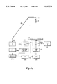
- FIG. 1 is a simplified illustration of a spacecraft on which a calibration arrangement with which an antenna attitude determination scheme according to an aspect of the invention may be used;
- FIG. 2 is a simplified block diagram of various systems associated with the antennas of FIG. 1;
- FIG. 3 is a simplified diagram in block and schematic form of an receive antenna array calibration scheme with which an array antenna attitude or beam pointing method may be used according to an aspect of the invention
- FIG. 4a is a simplified diagram in block and schematic form of an transmit antenna array calibration scheme
- FIG. 4b is a simplified block of a transmit calibration scheme showing the signals used to obtain amplitude and phase measurements of the phased-array elements
- FIG. 5 is a simplified block diagram of a spacecraft including the beam direction control calibration arrangement as described in conjunction with FIGS. 1 through 5, together with ground stations which receive the transmitted signal, for aiding in determining the beam direction or pointing of the transmit antenna.
- FIG. 1 is a simplified illustration of a spacecraft on which a calibration arrangement according to an aspect of the invention may be mounted.
- a spacecraft 10 includes a body 12, illustrated as a rectangular block.
- Body 12 supports first and second solar panels 14a and 14b, which are mounted to track the sun, for producing electricity for powering the various electrical portions of the spacecraft 10.
- Body 12 of spacecraft 10 also supports an array antenna 16, which may be dedicated to a receiving function.
- An array antenna 18 is dedicated to a transmitting function.
- Receiving antenna array 16 is associated with a receive antenna calibration antenna or probe 16p held in a fixed nominal position before receiving antenna array 16 by a support 16s.
- Transmit antenna array 18 is associated with a transmit antenna calibration antenna or probe 18p held in a fixed nominal position before transmit antenna array 18 by a support 18s.
- FIG. 2 is a simplified block diagram of various systems associated with antennas 16 and 18 of FIG. 1.
- receive antenna array 16 includes a signal port 16sp, from which signals received by the receive antenna array 16 are coupled to a common movable element 212m of a switch illustrated as 212.
- Receive antenna array 16 also includes a control or beam conditioning input port 16c, to which digital control signals are applied for control of the state of all of the control elements (phase shifters and attenuators or gain-control amplifiers) of the array. In general, there is one phase shifter and one attenuator for each antenna element of the array 16.
- Switch 212 includes a movable common element 212m which can be switched between contact with a calibration (CAL) terminal and contact with a traffic (TFK) terminal.
- CAL calibration
- TFK traffic
- the traffic terminal of switch 212 is connected to a traffic signal processing block 214, which performs processing which may be applicable to the traffic signals before transmissions are performed.
- processing block 214 represents frequency-shifting of the signals which are to be retransmitted to the Earth, and in one aspect performs routing of signals of various frequencies so that they are applied to selected ports of one or more beamformers (not illustrated) which determine which of several spot (or other shaped) beams carries that particular signal to its destination.
- the processed signals from block 214 are applied to the traffic (TFK) port of a switching arrangement 216.
- Switching arrangement 216 includes a common movable element 216m which is switchable to contact either a traffic (TFK) terminal or a calibration (CAL) terminal.
- the common element 216m is connected to the signal port 18sp of transmit array antenna 18.
- switch arrangements 212 and 216 are in their alternate positions (the positions indicated by the phantom movable elements 212p and 216p). With the switches 212 and 216 so set, the traffic signals received by receive antenna 16 are coupled through switch 212 to traffic signal processor 214. The resulting processed traffic signals are applied through switch 216 to signal port 18sp of transmit array antenna 18, which transmits the traffic signals to the Earth.
- the signals received by receive array antenna 16 are expected to be received from particular regions of the Earth's surface which the beam(s) of the receiving antenna array 16 illuminate under control of beam control signals, generated by an antenna control unit (ACU) illustrated as a block 218, and applied to control signal input port 16c of receiving antenna array 16.
- ACU antenna control unit
- the concept of illumination of a region is well known in the antenna arts, and is not further described.
- the signals transmitted by transmit antenna array 18 are intended to illuminate particular region(s) of the surface under the control of the control signals generated by ACU 218 and applied to control signal input port 18c of transmit antenna array 18.
- ACU 218 In order to assure that the beam direction and or shape as controlled by ACU 218 are those intended, it may be desirable to perform a calibration from time to time in order to determine the actual phase shift imparted by the various phase shifters and or the attenuators of the receive antenna array 16 or the transmit antenna array 18.
- an orthogonal code generator 220 when enabled, sequentially generates antenna element control signals. These control signals are applied to the movable element m of a switching arrangement (switch) 222, which includes transmit (TX) and receive (RX) terminals.
- switch 222 When switch 222 is in the illustrated condition or state, the antenna element control signals produced by orthogonal code generator 220 are applied to control signal input port 16c of receive antenna array 16.
- a switch 224 is ganged with switch 222, to switch off (prevent the antenna 16 from receiving) the receive antenna array 16 control signals produced by ACU 218 during those intervals in which the encoder control signals are applied to the receive antenna array 16.
- switch 222 when switch 222 is in its alternate switching condition or state, illustrated by the phantom position of movable element 222m, the encoder signals are applied by way of switch 222 to the control signal input port 18c of transmit antenna array 18.
- switch 222 routes the control signals from orthogonal code generator 220 to control signal input port 18c of transmit antenna array 18, a switch 226, which is ganged with switch 222 for simultaneous actuation therewith, decouples the control signals generated by ACU 218 from the control input port 18c of transmit antenna array 18.
- the encoding signals generated by orthogonal code generator 220 are coupled to the control signal input port of either the receive antenna array 16 or the transmit antenna array 18.
- the signals produced by orthogonal code generator 220 are known signal sets such as those described, for example, in U.S. Pat. No. 5,572,219, issued Nov. 5, 1996 in the name of Silverstein et al., and their application to near-field calibration is described below.
- a receive antenna array calibration tone generator 228 is connected by way of support 16s to receive antenna array probe or antenna 16p.
- generator 228 When generator 228 is enabled, the tone is generated, and radiated by probe 16p.
- receive antenna array 16 receives the tone, modulated or encoded by the calibration control signal from orthogonal code generator block 220.
- the signal produced at receive antenna array signal port 16sp is the receive antenna array calibration tone encoded or modulated with the calibration control signal from orthogonal code generator block 220.
- a transmit antenna array calibration tone generator 230 is connected to a calibration (CAL) terminal of switch arrangement 216.
- the common movable element 216m of switch 216 makes contact with calibration terminal CAL, and the tone is applied to the signal input port 18sp of transmit antenna array 18.
- the control signals produced by orthogonal code generator 220 are applied over switches 222 and 226 (in their alternate positions, indicated by dash lines) to the control input port 18c of transmit antenna array 18.
- the transmit calibration tone applied as radiated by transmit antenna array 18 is encoded with or modulated by the signal generated by orthogonal code generator 220.
- the modulated or encoded transmitted signal is received by probe 18p and coupled by way of a transmission line extending through support 18s to a receiver arrangement 240, which may be as simple as a filter for excluding unwanted signals, a downconverter, or a cascade of a filter with a downconverter.
- the received signals from blocks 240 and 242 are applied to a switching arrangement 244, which is illustrated as including a receive (RX) terminal, a transmit (TX) terminal, and a common movable element 244m.
- a switching arrangement 244 which is illustrated as including a receive (RX) terminal, a transmit (TX) terminal, and a common movable element 244m.
- RX receive
- TX transmit
- common movable element 244m common movable element
- Block 246a represents an analog-to-digital converter for converting the analog signals into digital form
- block 246b represents a decoder
- block 246c represents a processor, for decoding the encoded or modulated calibration signals, and for determining the phase shifts and or attenuations represented by the various bits of the control signals.
- the resulting information is applied over a signal path represented as 248 to the antenna control unit 18, to update the ACU with current phase shift and attenuation values.
- the arrangement of FIG. 3 is particularly advantageous for use on a spacecraft, because the signal-to-noise ratio can be favorable by comparison with remote arrangements in which the calibration signal source is on the Earth. Also, the on-board calibration scheme allows the antenna to be tested on the Earth before launch of the spacecraft. Also, the arrangement of FIG. 2 re-uses parts of the calibration structure, which is advantageous in a spacecraft context.
- FIG. 3 is a simplified diagram in block and schematic form of an receive antenna array calibration scheme, with which a phased-array antenna attitude determination or beam direction determination method may be used in accordance with an aspect of the invention.
- the arrangement of FIG. 3 is a subset of the arrangement of FIG. 2, lacking the transmit antenna array calibration arrangement.
- elements corresponding to those of FIG. 2 are designated by like reference numerals.
- the signal from receive block 242 is coupled to an ADC block 246a, which converts the analog signals into digital form (if necessary).
- the digital signals are applied to a decoder block 246b, which decodes the signals.
- the processor of block 246c determines, from the decoded signals, the phase shift or attenuation values which the elemental phase shifters or attenuators take on in response to the various bits of the control signal.
- the tone generator 228 couples a calibration tone signal to near-field probe or antenna 16p, which transmits the tone, as suggested by photon symbol 310.
- the receiving antenna array 16 receives the signal from antenna or probe 16p, together with traffic signals (if any) from other sources, and modulates the received signal in accordance with the control signals applied to control signal input port 16c.
- the modulated received signals are produced at signal port 16sp.
- movable element 212m of switch 212 couples the received signals to a user device (not illustrated).
- switch 212 couples the modulated tone to receiver 242.
- orthogonal code generator 220 produces appropriate orthogonal signal streams, which, when coupled to control input port 16c by switch 224 in a calibration mode, cause the received signal (the tone and the traffic signals) at port 16sp to be modulated with the coding.
- the signals so received are applied to receiver 242, and the received signals are coupled to a decoder 246a.
- the decoded signals are applied to the processor 246b, which produces signals representing the values of the phase shifts associated with each phase bit value of the control signal, the attenuation associated with each attenuation bit value of the control signal, or both. These signals are made available over a signal path 248 to an ACU 218.
- the ACU control signals are coupled over switch 224 to the control input port 16c of receive antenna array 16.
- FIG. 3 for near-field calibration of the phase of the phase shifters, amplitude controllers, or both, which are associated with each of the elements of the receive array 16, provides an improvement over the abovementioned technique described by Silverstein et al., because the Silverstein technique is a far-field measurement, and as such requires a remote transmitter or receiver, together with coherent synchronization and timing, which is difficult to perform over substantial distances.
- the use of a near-field probe allows the calibration to be performed in a simpler manner. Knowledge of the radiation patterns of the individual elements of the array, and their locations in the array and relative to the probe, allow the computation of correction factors.
- correction factors are then used to correct or calibrate the near-field measurements to determine the far-field radiation patterns which result from various phase or amplitude controller settings. These correction factors would apply to either a receive phased-array antenna as in FIG. 3, a transmit phased-array antenna as in FIG. 4a, or both.
- the near-field probe measurements are used to determine far-field results, so that the phase-shifter and amplitude-controller settings associated with the array elements, which give the desired far-field radiation patterns, can be determined.
- the array is calibrated. Details of the calibration technique are described below in conjunction with FIG. 4b.
- tone generator 230 couples unmodulated calibration signals to signal port 18sp of transmit antenna array 18 by way of switch 216 in a calibration mode of operation. Transmit antenna array 18 also receives coded signals at its control signal input port 18c by way of switch 226 in its calibration position. The coding applied to the control signal input port 18c of antenna 18 causes modulation of the calibration tone from generator 230, so that a modulated tone is transmitted, as suggested by photon symbol 410, to near-field probe antenna 18p. The encoded signal is received by probe 18p, and coupled to receiver 240. Receiver 240 provides processing as described above, and couples the received signals to decoder 246a. Decoder 246b decodes the signals, and the decoded signals are applied to processor 246c.
- Processor 246c determines the values of the phase shifts associated with each phase bit value of the control signal, the attenuation associated with each attenuation bit value of the control signal, or both. These signals are made available over a signal path 248 to an ACU 218. In a traffic mode of operation, the ACU control signals are coupled over switch 224 to the control input port 16c of receive antenna array 16.
- control signals when applied to the control input port 16c or 18c of the receive antenna array or the transmit antenna array, respectively, modulate or encode the calibration tones.
- FIG. 4b is a simplified functional diagram illustrating the operation of the arrangement of FIG. 4a for near-field calibration.
- coherent source 230 applies an unmodulated tone to a common port of a beamformer 232 which is associated with array antenna 18.
- Beamformer 232 also includes a control input port 232c.
- the orthogonal codes as suggested by Silverstein et al. are applied to control input port 232c of beamformer 232 from orthogonal code generator or source 220.
- the orthogonal codes individually modulate the various phase shifters and amplitude controllers with separately identifiable codes, so that the signals applied to the various elemental antennas 18 1 , 18 2 , . . . , 18 n , . . .
- the various paths between the common input port 232i and each of the individual antenna elements 18 1 , 18 2 , . . . , 18 n , . . . , 18 N of array 18 are modulated with different codes, so that a unique coding sequence is applied to each of the element paths, by toggling at least one of amplitude and phase so as to provide a unique identifier for the signal path.
- each elemental antenna 18 1 , 18 2 , . . . , 18 n , . . . , 18 N of the array 18 receives the radiated signals from each elemental antenna 18 1 , 18 2 , . . . , 18 n , . . . , 18 N of the array 18 with a phase and amplitude which depends upon the separation r n between the individual elemental antennas and the probe, and the angular separation as it affects the radiation patterns of the elemental antennas and the probe.
- the signals received by the probe are applied to coherent receiver 240, and the resulting signal, which is a composite of all of the individual signals from the individual elemental antennas of the array, are applied to decoder 246. Decoder 246 also receives the orthogonal code information, so that the individual elemental signals can be extracted from the composite signal.
- the resulting unprocessed signals are designated E 1 , E 2 , . . . , E n , . . . , E N .
- Each of these signals represents one of the signals flowing in an independent path extending between one of the various individual antenna elements 18 1 , 18 2 , . . . , 18 n , . . . , 18 N of array antenna 18 and the near-field probe 18p. Consequently, the unique coding sequence applied to each of the element paths allows for simultaneous measurement of all of the elements of the phased-array antenna. More specifically, each of the signals has its relative amplitude and phase a n e jk0n encoded with the orthogonal coding sequence.
- the procedure for using a Hadamard matrix to generate the orthogonal encoding and decoding sequences is described in the abovementioned Silverstein et al. patent.
- the processing of the signals received by the probe is performed by cross-correlating the received signal with the orthogonal codes, to produce the unprocessed signals E 1 , E 2 , . . . , E n , . . . , E N .
- r n is the distance between the n th element and the probe
- k is the wave number 2 ⁇ / ⁇
- g n ( ⁇ n e ) are the element patterns
- ⁇ n e defines the angle relating the element pattern to the probe position
- f( ⁇ n p ) is the probe pattern
- ⁇ n p defines the angle relating the probe pattern to the element position.
- the recovered amplitude and phase weights for each of the elements of the antenna array are then used in conventional manner to calibrate the array, and to provide for correction of the far-field pattern.
- the receive array of FIG. 3 is calibrated in a manner corresponding to that of the transmit antenna of FIG. 4a, by applying the coherent tone source to the transmitting probe, and the receiver/decoder at the output port of a beamformer associated with the receive antenna.
- the encoding is performed in the receive beamformer, and the same coherent reception, decoding, and scaling procedure is performed to recover the relative phase and amplitude for each element of the receive antenna array.
- the determination of the radiation patterns of the various elemental antennas of the array may require actual measurements of elements located at representative positions in the array, as for example at the center and at the edges. Similarly, actual measurements may be required in order to determine the radiation pattern of the probe antenna.
- FIG. 5 is a simplified block diagram of a spacecraft including the beam direction control calibration arrangement as described in conjunction with FIGS. 1 through 5, together with ground stations which receive the transmitted signal, for aiding in determining the beam direction or pointing of the transmit antenna of the spacecraft.
- the spacecraft 10 includes array transmit antenna 18, as described above.
- a first ground station 610a includes a receiving antenna 616a and a receiver 620a, which receives signals transmitted from transmitting antenna 18 of the spacecraft.
- a second ground station 616b includes a receive antenna 616b and a receiver 620b.
- the pointing direction in two dimensions can be determined from the information obtained at either ground station, but determination of the three-axis pointing direction requires information obtained at a minimum of two separated sites.
- the transmit antenna is illustrated as being located on a spacecraft, which may be in motion relative to the ground stations, it may be necessary, or at least practical, to provide separate synchronization scheme, rather than relying on accurate clocks at each location.
- a synchronizing-signal transmit antenna 608 which transmits timing signals, by way of a path designated 611, to at least one ground antenna, illustrated as an antenna 612.
- the information from the two ground stations 610a and 610b is coupled, by paths 618a and 618b, to a processor 622, which can perform some of the processing to determine the three-axis pointing direction of the transmit antenna 18. As mentioned above, if only two-direction pointing is required, information from only one ground station is required, and the additional information, as from ground station 610b, in not needed.
- transmit antenna calibration tone generator 230 produces the desired test tone, which is applied to port 18sp of the transmit antenna.
- This tone does not need to be modulated with the Hadamard information which is required for antenna control unit calibration as described above, but may be modulated or unmodulated, just so long as the signal as transmitted can be received by at least one ground station of FIG. 5. If the transmit antenna 18 generates multiple simultaneous beams, and these beams can be separately accessed, as by different frequencies of the test tones, the beams may be simultaneous.
- the beams defined by the state of the antenna control unit must be time-sequenced, but in either case, beams pointing in various directions must "impinge” on ground station 610a of FIG. 5.
- the antenna beam shapes are well defined by the settings of the phase and amplitude controllers of the transmit antenna. At the ground station or ground stations of FIG. 5, at least the amplitude or phase, or both, of the received signals of each beam is (are) determined, with the aid of the synchronization information transmitted from antenna 608.
- a ground station receives multiple pieces of information about each beam. Taking a simplistic example, if a beam is sequenced to locations which should be centered on a ground station, the signals received at the ground station for each beam should be of equal amplitude. Any systematic difference in attitude can be interpreted as a deviation of the "center" around which the beams are sequenced, and this difference is the antenna pointing offset or attitude offset. Much more sophisticated processing can be performed, but is beyond the scope of this invention.
- the receive antenna attitude or pointing determination is made in a similar manner to that described above for the transmit antenna. More particularly, a ground or other remote station(s) transmits a tone, which is received by the receiving antenna (16 of FIG. 2). The position of the beam generated by the receive antenna is rotated about an axis centered on the remote site, and the amplitude and or phase of the received signal are determined for various beam directions. If the amplitudes and or phases are constant, then the beam is centered on the remote transmission site, then the beam direction is known. If the amplitude and or phases deviate from a constant value in the various beams, the deviations are indicative of the beam pointing error, and the processor determines the angular error. A complete determination of the pointing in three dimensions can be established with two or more separated remote transmission sites.
- FIG. 2 performs calibration on only one of the receive and transmit antennas at a time, this is because a single transmit and single receive antenna have been illustrated. If there were plural transmit and receive antennas, some transmit antennas could be calibrated at the same time receive antennas were being calibrated. Those skilled in the art know that the meaning of the term "between" in electrical systems may be different from the meaning in physical arrangements, and must be interpreted in accordance with the relevant art area. While the near-field calibration invention as described is mounted on a spacecraft, it may instead be used with terrestrial antennas. While a single probe has been described as being used in conjunction with each antenna being calibrated, more than one may be used if desired.
- a near-field calibration system (FIGS. 3 or 4) calibrates at least one of (either or both of) the phase and amplitude controllers of the individual elements of an phased antenna array (16, 18).
- the phased antenna array (16, 18) includes a signal port (16sp, 18sp) for each antenna beam which is generated, and also includes a control signal input port (16c, 18c) to which control signals may be applied for control of the phase and amplitude controllers.
- the phased antenna array (16, 18) can be operated in a normal signal-handling or traffic mode and in a calibration mode.
- a calibration probe (16p, 18p) is held at a fixed location relative to the phased antenna array (16, 18), and within the near-field of the phased antenna array (16, 18).
- a calibration tone generator (228, 230) generates a calibration tone signal.
- the calibration tone generator (228, 230) is (a) coupled to at least one of the signal ports (16sp, 18sp) of the phased antenna array (16, 18) for the case in which the phased antenna array (16, 18) is used as a transmit antenna during normal operation, or is (b) coupled to the calibration probe (16p, 18p) for the case in which the phased antenna array (16, 18) is used as a receive antenna during normal operation.
- a calibration encoder or orthogonal code generating arrangement (220) is coupled to the beam conditioning control port (16c, 18c) of the phased antenna array (16, 18), for, during calibration, sequentially setting at least some of the phase shifters (or attenuators, or both) of the phased antenna array (16, 18) with a plurality of sets of values.
- Each of the sets of values set by the orthogonal code generating arrangement (220) imposes a coding on the calibration tone signal, to thereby sequentially generate calibration signals encoded with sets of values.
- Each set of values so encoded onto the calibration signals is orthogonal to other sets of values with which the calibration signals are encoded.
- the calibration probe (16p, 18p) receives the calibration tone signals sequentially encoded with mutually orthogonal values, and in the case in which the phased antenna array (16, 18) is used as a receive antenna during normal operation, the calibration tone signals sequentially encoded with mutually orthogonal values are generated at the at least one of the signal port (16sp, 18sp)s of the phased antenna array (16, 18).
- the system includes a decoder (246; 246b) for decoding signals encoded with the mutually orthogonal values, for generating decoded signals therefrom.
- An encoded signal coupling arrangement (18s, 240, 244m) is (a) coupled to the calibration probe (18p) and to the decoder (246; 246b) in the case in which the phased antenna array (18) is operated as a transmit antenna in the normal mode of operation and (b) coupled to the decoder (246; 246b) and to the signal port (16sp) of the phased antenna array (16) in the case in which the antenna is operated as a receive antenna in the normal mode of operation, for coupling the encoded signals to the decoder (246; 246b). Consequently, the decoder (246; 246b) generates decoded signals.
- a processor (246, 246c) is coupled to the decoder (246; 246b), for processing the decoded signals, for generating signals representing at least values of one of phase shift and attenuation, or both if appropriate.
- a coupling arrangement (248) is coupled to the processor (246, 246c) and to the antenna control unit (218), for coupling to the antenna control unit (218) the signals representing at least the values of phase shift, attenuation, or both, which may have been determined by the calibration system.
- An antenna system includes an transmit antenna array (18) including a signal port (18sp) and also including a beam conditioning signal control input port (18c) coupled to at least controllable phase shifters (18pc) of the transmit antenna array (18).
- a transmit calibration probe (18p) is affixed at a nominal location in the near field of the transmit antenna array (18).
- a transmit antenna switching arrangement (216) includes at least common (216m), calibration (216CAL), and transmit (216TFK) ports, with the common port (216m) being coupled to the signal port (18sp) of the transmit antenna array (18).
- the antenna system includes a source (230) of transmit antenna array (18) calibration signals.
- a transmit antenna array (18) calibration signal coupling arrangement (231) is coupled to the source (230) of transmit antenna array (18) calibration signals and to the calibration port (216CAL) of the transmit antenna switching arrangement (216), for controllably coupling the transmit antenna array (18) calibration signals to the signal port (18sp) of the transmit antenna array (18), so that the transmit antenna array (18) calibration signal, when applied to the signal port (18sp) of the transmit antenna array (18), is transmitted by the transmit antenna array (18).
- a calibration orthogonal code generator or encoder (220) sequentially generates sets of values, each set of values being orthogonal to other sets of values.
- a transmit antenna encoding signal coupling arrangement (222TX, 226, 227) is coupled to the calibration orthogonal code generator or encoder (220) and to the beam conditioning control signal port (18c) of the transmit antenna array (18), for, during calibration, coupling the calibration encoding signals to the beam conditioning control signal port (18c) of the transmit antenna array (18).
- the antenna system also includes an receive array antenna (16).
- the receive array antenna (16) includes a signal port (16sp) and also includes a beam conditioning signal control input port (16c) coupled to at least controllable phase shifters (16pc) of the receive array antenna (16).
- a receive calibration probe is affixed at a nominal location in the near field of the receive antenna array (16).
- a receive antenna switching arrangement (212) includes at least common (212m), calibration (212CAL), and receive (212TFK) ports.
- the common port (212m) of the receive antenna switching arrangement (212) is coupled (by path 210) to the signal port (16sp) of the receive antenna array (16).
- a source (228) of receive antenna array calibration signals is provided.
- An receive antenna array calibration signal coupling arrangement (16s) is coupled to the source of receive antenna array calibration signals (228) and to the receive calibration probe (16p), for controllably coupling the receive antenna array calibration signals to the receive calibration probe (16p), as a result of which, or whereby, the receive antenna array calibration signal is transmitted by the receive calibration probe (16p) and is received by the receive antenna array (16).
- a receive antenna encoding signal coupling arrangement (222m, 224, 225) is coupled to the calibration orthogonal code generator or encoder (220) and to the beam conditioning control signal port (16c) of the receive antenna array (16), for, during calibration, sequentially setting at least some of the phase shifters (16ps) of the receive antenna array (16) with the plurality of sets of values, whereby the receive antenna array (16) produces, at its signal port (16sp), receive antenna array calibration signals sequentially encoded with mutually orthogonal values.
- a transmit/receive calibration switch including transmit signal port (244TX), receive signal port (244RX), and a common port (244m), couples to its common port (244m) signals applied to one of its transmit signal port (244TX) and its receive signal port (244RX).
- a first encoded signal coupling arrangement (18s, 239, 240) is coupled to the transmit calibration probe (18p) and to the transmit signal port (244TX) of the transmit/receive calibration switch (244), for coupling the transmit antenna array (18) calibration signals sequentially encoded with mutually orthogonal values to the transmit/receive calibration switch (244), as a result of which, or whereby, the transmit antenna array (18) calibration signals sequentially encoded with mutually orthogonal values are produced at the common port (244m) of the transmit/receive calibration switch (244) in an transmit antenna array (18) calibration mode of operation.
- a second encoded signal coupling arrangement (242) is coupled to the calibration port (212CAL) of the receive antenna switching arrangement (212) and to the receive port (244RX) of the transmit/receive calibration switch (244), whereby the receive antenna array calibration signals sequentially encoded with mutually orthogonal values are produced at the common port (244m) of the transmit/receive calibration switch (244) in an receive antenna array calibration mode of operation.
- An analog-to-digital converter (246ADC) includes an input port (246i) coupled to the common port (244m) of the transmit/receive calibration switch (244), for converting into digital form those analog signals applied to the input port (246i) of the analog-to-digital converter (246ADC), to thereby generate a digital version of the transmit antenna array (18) calibration signals sequentially encoded with mutually orthogonal values in the transmit antenna array (18) calibration mode of operation and a digital version of the receive antenna array calibration signals sequentially encoded with mutually orthogonal values in the receive antenna array calibration mode of operation.
- a signal processor (246b, 246c) is coupled to the analog-to-digital converter (246a), for decoding that one of the digital version of the transmit antenna array (18) calibration signals sequentially encoded with mutually orthogonal values and the digital version of the receive antenna array calibration signals sequentially encoded with mutually orthogonal values which is produced by the analog-to-digital converter (246ADC), to thereby generate signals representing the relationship between each bit applied to each of the phase shifters and the resulting phase of the phase shifters.
- each of the first encoded signal coupling arrangement (18s, 239, 240) and the second encoded signal coupling arrangement (242) comprises an electromagnetic filter for rejecting unwanted frequencies, to thereby generate filtered signals, a frequency converter, or both.
- the frequency converter may be a downconverter.
- a traffic signal processor (214) may be coupled between the receive (212TFK) port of the receive antenna switching arrangement (212) and the transmit (216TFK) port of the transmit antenna switching arrangement (216).
Abstract
Description
α.sub.n e.sup.jk0.sbsp.n= S.sub.n E.sub.n 3
Claims (4)
Priority Applications (1)
| Application Number | Priority Date | Filing Date | Title |
|---|---|---|---|
| US09/352,509 US6163296A (en) | 1999-07-12 | 1999-07-12 | Calibration and integrated beam control/conditioning system for phased-array antennas |
Applications Claiming Priority (1)
| Application Number | Priority Date | Filing Date | Title |
|---|---|---|---|
| US09/352,509 US6163296A (en) | 1999-07-12 | 1999-07-12 | Calibration and integrated beam control/conditioning system for phased-array antennas |
Publications (1)
| Publication Number | Publication Date |
|---|---|
| US6163296A true US6163296A (en) | 2000-12-19 |
Family
ID=23385412
Family Applications (1)
| Application Number | Title | Priority Date | Filing Date |
|---|---|---|---|
| US09/352,509 Expired - Lifetime US6163296A (en) | 1999-07-12 | 1999-07-12 | Calibration and integrated beam control/conditioning system for phased-array antennas |
Country Status (1)
| Country | Link |
|---|---|
| US (1) | US6163296A (en) |
Cited By (377)
| Publication number | Priority date | Publication date | Assignee | Title |
|---|---|---|---|---|
| US6307507B1 (en) * | 2000-03-07 | 2001-10-23 | Motorola, Inc. | System and method for multi-mode operation of satellite phased-array antenna |
| US20030008614A1 (en) * | 2000-03-03 | 2003-01-09 | Hanson Duke Edward | Mobile satellite communication system utilizing polarization diversity combining |
| US6507315B2 (en) | 2001-05-03 | 2003-01-14 | Lockheed Martin Corporation | System and method for efficiently characterizing the elements in an array antenna |
| US20030143969A1 (en) * | 2002-01-22 | 2003-07-31 | Buznitsky Mitchell A. | Determination and processing for fractional-N programming values |
| US6636173B2 (en) | 2001-12-20 | 2003-10-21 | Lockheed Martin Corporation | Calibration system and method for phased array antenna using near-field probe and focused null |
| WO2003087872A1 (en) * | 2002-04-11 | 2003-10-23 | Totalförsvarets Forskningsinstitut | Method for verifying dynamically a multiple beam antenna placed on a vehicle |
| US20030204640A1 (en) * | 2002-04-30 | 2003-10-30 | Nokia Corporation | Method and device for management of tree data exchange |
| US6676087B2 (en) | 2001-12-07 | 2004-01-13 | The Boeing Company | Spacecraft methods and structures with beacon-receiving field-of-view matched to beacon station window |
| US6708003B1 (en) * | 1999-12-16 | 2004-03-16 | Northrop Grumman Corporation | Optical energy transmission system utilizing precise phase and amplitude control |
| US20040061644A1 (en) * | 2002-09-11 | 2004-04-01 | Lockheed Martin Corporation | CCE calibration with an array of calibration probes interleaved with the array antenna |
| US6738017B2 (en) | 2002-08-06 | 2004-05-18 | Lockheed Martin Corporation | Modular phased array with improved beam-to-beam isolation |
| US20040196203A1 (en) * | 2002-09-11 | 2004-10-07 | Lockheed Martin Corporation | Partly interleaved phased arrays with different antenna elements in central and outer region |
| US20040208636A1 (en) * | 2002-03-29 | 2004-10-21 | Reynolds Timothy N. | Phase tracking multichannel link |
| US20050012659A1 (en) * | 2003-06-25 | 2005-01-20 | Harris Corporation | Chirp-based method and apparatus for performing phase calibration across phased array antenna |
| US6861975B1 (en) * | 2003-06-25 | 2005-03-01 | Harris Corporation | Chirp-based method and apparatus for performing distributed network phase calibration across phased array antenna |
| US7050019B1 (en) | 2002-09-11 | 2006-05-23 | Lockheed Martin Corporation | Concentric phased arrays symmetrically oriented on the spacecraft bus for yaw-independent navigation |
| WO2006091917A2 (en) * | 2005-02-24 | 2006-08-31 | Bae Systems Information And Electronic Systems Integration Inc. | Method for detection of faulty antenna array elements |
| DE102005011128A1 (en) * | 2005-03-10 | 2006-09-14 | Imst Gmbh | Electronically controllable antenna e.g. planar patch antenna, for transceiver in airplane, has sensors directly arranged in reactive near field of emitter units to measure and calibrate amplitude and/or phase of units |
| US20070060201A1 (en) * | 2005-09-14 | 2007-03-15 | Nagy Louis L | Self-structuring antenna with addressable switch controller |
| US7218273B1 (en) * | 2006-05-24 | 2007-05-15 | L3 Communications Corp. | Method and device for boresighting an antenna on a moving platform using a moving target |
| US20080129613A1 (en) * | 2006-12-05 | 2008-06-05 | Nokia Corporation | Calibration for re-configurable active antennas |
| US20080153433A1 (en) * | 2006-12-21 | 2008-06-26 | Nokia Corporation | Phase and power calibration in active antennas |
| US20080165050A1 (en) * | 2002-08-19 | 2008-07-10 | Q-Track Corporation | Near field electromagnetic positioning calibration system and method |
| US7423578B1 (en) | 2006-06-09 | 2008-09-09 | Lockheed Martin Corporation | Split aperture array for increased short range target coverage |
| US20080291087A1 (en) * | 2006-06-09 | 2008-11-27 | Lockheed Martin Corporation | Split aperture array for increased short range target coverage |
| US20090153394A1 (en) * | 2007-12-17 | 2009-06-18 | Navarro Julio A | Method for accurate auto-calibration of phased array antennas |
| US20090267835A1 (en) * | 2008-04-25 | 2009-10-29 | Lockheed Martin Corporation | Foldable antenna for reconfigurable radar system |
| US20100164782A1 (en) * | 2008-12-30 | 2010-07-01 | Astrium Limited | Calibration apparatus and method |
| FR2941333A1 (en) * | 2009-01-20 | 2010-07-23 | Satimo Sa | SYSTEM FOR EMITTING ELECTROMAGNETIC BEAMS WITH ANTENNA NETWORK. |
| US20100220003A1 (en) * | 2007-08-31 | 2010-09-02 | Bae Systems Plc | Antenna calibration |
| US20100245158A1 (en) * | 2007-08-31 | 2010-09-30 | Bae Systems Plc | Antenna calibration |
| US20100253570A1 (en) * | 2007-08-31 | 2010-10-07 | Bae Systems Plc | Antenna calibration |
| US20100253571A1 (en) * | 2007-08-31 | 2010-10-07 | Bae Systems Plc | Antenna calibration |
| US20110065392A1 (en) * | 2009-09-16 | 2011-03-17 | Samsung Electronics Co. Ltd. | Wireless device and signal path configuration method thereof |
| US7986742B2 (en) | 2002-10-25 | 2011-07-26 | Qualcomm Incorporated | Pilots for MIMO communication system |
| WO2011123310A2 (en) * | 2010-04-01 | 2011-10-06 | Massachusetts Institute Of Technology | Iterative clutter calibration with phased array antennas |
| US8134976B2 (en) | 2002-10-25 | 2012-03-13 | Qualcomm Incorporated | Channel calibration for a time division duplexed communication system |
| US8145179B2 (en) | 2002-10-25 | 2012-03-27 | Qualcomm Incorporated | Data detection and demodulation for wireless communication systems |
| US8169944B2 (en) | 2002-10-25 | 2012-05-01 | Qualcomm Incorporated | Random access for wireless multiple-access communication systems |
| US8194770B2 (en) | 2002-08-27 | 2012-06-05 | Qualcomm Incorporated | Coded MIMO systems with selective channel inversion applied per eigenmode |
| US8203978B2 (en) | 2002-10-25 | 2012-06-19 | Qualcomm Incorporated | Multi-mode terminal in a wireless MIMO system |
| US8208364B2 (en) | 2002-10-25 | 2012-06-26 | Qualcomm Incorporated | MIMO system with multiple spatial multiplexing modes |
| US8218609B2 (en) | 2002-10-25 | 2012-07-10 | Qualcomm Incorporated | Closed-loop rate control for a multi-channel communication system |
| US20120206291A1 (en) * | 2011-02-11 | 2012-08-16 | Src, Inc. | Bench-top measurement method, apparatus and system for phased array radar apparatus calibration |
| US8320301B2 (en) | 2002-10-25 | 2012-11-27 | Qualcomm Incorporated | MIMO WLAN system |
| US8358714B2 (en) | 2005-06-16 | 2013-01-22 | Qualcomm Incorporated | Coding and modulation for multiple data streams in a communication system |
| US20130234883A1 (en) * | 2012-02-24 | 2013-09-12 | Futurewei Technologies, Inc. | Apparatus and Method for an Active Antenna System with Near-field Radio Frequency Probes |
| US8570988B2 (en) * | 2002-10-25 | 2013-10-29 | Qualcomm Incorporated | Channel calibration for a time division duplexed communication system |
| US20130328721A1 (en) * | 2012-06-06 | 2013-12-12 | California Institute Of Technology | Feature in antenna pattern for pointing and orientation determination |
| US8855226B2 (en) | 2005-05-12 | 2014-10-07 | Qualcomm Incorporated | Rate selection with margin sharing |
| US8873365B2 (en) | 2002-10-25 | 2014-10-28 | Qualcomm Incorporated | Transmit diversity processing for a multi-antenna communication system |
| US9019153B1 (en) * | 2011-12-20 | 2015-04-28 | Raytheon Company | Calibration of large phased arrays using fourier gauge |
| US9154274B2 (en) | 2002-10-25 | 2015-10-06 | Qualcomm Incorporated | OFDM communication system with multiple OFDM symbol sizes |
| US9209523B2 (en) | 2012-02-24 | 2015-12-08 | Futurewei Technologies, Inc. | Apparatus and method for modular multi-sector active antenna system |
| US9473269B2 (en) | 2003-12-01 | 2016-10-18 | Qualcomm Incorporated | Method and apparatus for providing an efficient control channel structure in a wireless communication system |
| US9551785B1 (en) | 1999-04-07 | 2017-01-24 | James L. Geer | Method and apparatus for the detection of objects using electromagnetic wave attenuation patterns |
| RU2611581C1 (en) * | 2016-01-15 | 2017-02-28 | Акционерное общество "Научно-исследовательский институт точных приборов" | Shf range-finder |
| US9642107B1 (en) * | 2016-08-01 | 2017-05-02 | Space Systems/Loral, Inc. | Multi-channel satellite calibration |
| US9667317B2 (en) | 2015-06-15 | 2017-05-30 | At&T Intellectual Property I, L.P. | Method and apparatus for providing security using network traffic adjustments |
| US9674711B2 (en) | 2013-11-06 | 2017-06-06 | At&T Intellectual Property I, L.P. | Surface-wave communications and methods thereof |
| US9685992B2 (en) | 2014-10-03 | 2017-06-20 | At&T Intellectual Property I, L.P. | Circuit panel network and methods thereof |
| US9705561B2 (en) | 2015-04-24 | 2017-07-11 | At&T Intellectual Property I, L.P. | Directional coupling device and methods for use therewith |
| US9705610B2 (en) | 2014-10-21 | 2017-07-11 | At&T Intellectual Property I, L.P. | Transmission device with impairment compensation and methods for use therewith |
| US9722318B2 (en) | 2015-07-14 | 2017-08-01 | At&T Intellectual Property I, L.P. | Method and apparatus for coupling an antenna to a device |
| US9729197B2 (en) | 2015-10-01 | 2017-08-08 | At&T Intellectual Property I, L.P. | Method and apparatus for communicating network management traffic over a network |
| US9735833B2 (en) | 2015-07-31 | 2017-08-15 | At&T Intellectual Property I, L.P. | Method and apparatus for communications management in a neighborhood network |
| US9742462B2 (en) | 2014-12-04 | 2017-08-22 | At&T Intellectual Property I, L.P. | Transmission medium and communication interfaces and methods for use therewith |
| US9742521B2 (en) | 2014-11-20 | 2017-08-22 | At&T Intellectual Property I, L.P. | Transmission device with mode division multiplexing and methods for use therewith |
| US9749013B2 (en) | 2015-03-17 | 2017-08-29 | At&T Intellectual Property I, L.P. | Method and apparatus for reducing attenuation of electromagnetic waves guided by a transmission medium |
| US9749053B2 (en) | 2015-07-23 | 2017-08-29 | At&T Intellectual Property I, L.P. | Node device, repeater and methods for use therewith |
| US9748626B2 (en) | 2015-05-14 | 2017-08-29 | At&T Intellectual Property I, L.P. | Plurality of cables having different cross-sectional shapes which are bundled together to form a transmission medium |
| US9769020B2 (en) | 2014-10-21 | 2017-09-19 | At&T Intellectual Property I, L.P. | Method and apparatus for responding to events affecting communications in a communication network |
| US9768833B2 (en) | 2014-09-15 | 2017-09-19 | At&T Intellectual Property I, L.P. | Method and apparatus for sensing a condition in a transmission medium of electromagnetic waves |
| US9769128B2 (en) | 2015-09-28 | 2017-09-19 | At&T Intellectual Property I, L.P. | Method and apparatus for encryption of communications over a network |
| US9780834B2 (en) | 2014-10-21 | 2017-10-03 | At&T Intellectual Property I, L.P. | Method and apparatus for transmitting electromagnetic waves |
| US9787412B2 (en) | 2015-06-25 | 2017-10-10 | At&T Intellectual Property I, L.P. | Methods and apparatus for inducing a fundamental wave mode on a transmission medium |
| US9787103B1 (en) | 2013-08-06 | 2017-10-10 | Energous Corporation | Systems and methods for wirelessly delivering power to electronic devices that are unable to communicate with a transmitter |
| US9793951B2 (en) | 2015-07-15 | 2017-10-17 | At&T Intellectual Property I, L.P. | Method and apparatus for launching a wave mode that mitigates interference |
| US9793758B2 (en) | 2014-05-23 | 2017-10-17 | Energous Corporation | Enhanced transmitter using frequency control for wireless power transmission |
| US9793954B2 (en) | 2015-04-28 | 2017-10-17 | At&T Intellectual Property I, L.P. | Magnetic coupling device and methods for use therewith |
| US9791552B1 (en) * | 2014-11-19 | 2017-10-17 | Src, Inc. | On-site calibration of array antenna systems |
| US9793955B2 (en) | 2015-04-24 | 2017-10-17 | At&T Intellectual Property I, Lp | Passive electrical coupling device and methods for use therewith |
| US9800172B1 (en) | 2014-05-07 | 2017-10-24 | Energous Corporation | Integrated rectifier and boost converter for boosting voltage received from wireless power transmission waves |
| US9800080B2 (en) | 2013-05-10 | 2017-10-24 | Energous Corporation | Portable wireless charging pad |
| US9800327B2 (en) | 2014-11-20 | 2017-10-24 | At&T Intellectual Property I, L.P. | Apparatus for controlling operations of a communication device and methods thereof |
| US9806564B2 (en) | 2014-05-07 | 2017-10-31 | Energous Corporation | Integrated rectifier and boost converter for wireless power transmission |
| US9812890B1 (en) | 2013-07-11 | 2017-11-07 | Energous Corporation | Portable wireless charging pad |
| US9820146B2 (en) | 2015-06-12 | 2017-11-14 | At&T Intellectual Property I, L.P. | Method and apparatus for authentication and identity management of communicating devices |
| US9819230B2 (en) | 2014-05-07 | 2017-11-14 | Energous Corporation | Enhanced receiver for wireless power transmission |
| US9825674B1 (en) | 2014-05-23 | 2017-11-21 | Energous Corporation | Enhanced transmitter that selects configurations of antenna elements for performing wireless power transmission and receiving functions |
| US9824815B2 (en) | 2013-05-10 | 2017-11-21 | Energous Corporation | Wireless charging and powering of healthcare gadgets and sensors |
| US9831718B2 (en) | 2013-07-25 | 2017-11-28 | Energous Corporation | TV with integrated wireless power transmitter |
| US9838083B2 (en) | 2014-07-21 | 2017-12-05 | Energous Corporation | Systems and methods for communication with remote management systems |
| US9838896B1 (en) | 2016-12-09 | 2017-12-05 | At&T Intellectual Property I, L.P. | Method and apparatus for assessing network coverage |
| US9838078B2 (en) | 2015-07-31 | 2017-12-05 | At&T Intellectual Property I, L.P. | Method and apparatus for exchanging communication signals |
| US9843229B2 (en) | 2013-05-10 | 2017-12-12 | Energous Corporation | Wireless sound charging and powering of healthcare gadgets and sensors |
| US9843213B2 (en) | 2013-08-06 | 2017-12-12 | Energous Corporation | Social power sharing for mobile devices based on pocket-forming |
| US9843201B1 (en) | 2012-07-06 | 2017-12-12 | Energous Corporation | Wireless power transmitter that selects antenna sets for transmitting wireless power to a receiver based on location of the receiver, and methods of use thereof |
| US9847677B1 (en) | 2013-10-10 | 2017-12-19 | Energous Corporation | Wireless charging and powering of healthcare gadgets and sensors |
| US9847669B2 (en) | 2013-05-10 | 2017-12-19 | Energous Corporation | Laptop computer as a transmitter for wireless charging |
| US9847850B2 (en) | 2014-10-14 | 2017-12-19 | At&T Intellectual Property I, L.P. | Method and apparatus for adjusting a mode of communication in a communication network |
| US9847566B2 (en) | 2015-07-14 | 2017-12-19 | At&T Intellectual Property I, L.P. | Method and apparatus for adjusting a field of a signal to mitigate interference |
| US9847679B2 (en) | 2014-05-07 | 2017-12-19 | Energous Corporation | System and method for controlling communication between wireless power transmitter managers |
| US9853692B1 (en) | 2014-05-23 | 2017-12-26 | Energous Corporation | Systems and methods for wireless power transmission |
| US9853342B2 (en) | 2015-07-14 | 2017-12-26 | At&T Intellectual Property I, L.P. | Dielectric transmission medium connector and methods for use therewith |
| US9853458B1 (en) | 2014-05-07 | 2017-12-26 | Energous Corporation | Systems and methods for device and power receiver pairing |
| US9853485B2 (en) | 2015-10-28 | 2017-12-26 | Energous Corporation | Antenna for wireless charging systems |
| US9859758B1 (en) | 2014-05-14 | 2018-01-02 | Energous Corporation | Transducer sound arrangement for pocket-forming |
| US9859757B1 (en) | 2013-07-25 | 2018-01-02 | Energous Corporation | Antenna tile arrangements in electronic device enclosures |
| US9860075B1 (en) | 2016-08-26 | 2018-01-02 | At&T Intellectual Property I, L.P. | Method and communication node for broadband distribution |
| US9859756B2 (en) | 2012-07-06 | 2018-01-02 | Energous Corporation | Transmittersand methods for adjusting wireless power transmission based on information from receivers |
| US9866276B2 (en) | 2014-10-10 | 2018-01-09 | At&T Intellectual Property I, L.P. | Method and apparatus for arranging communication sessions in a communication system |
| US9866309B2 (en) | 2015-06-03 | 2018-01-09 | At&T Intellectual Property I, Lp | Host node device and methods for use therewith |
| US9866279B2 (en) | 2013-05-10 | 2018-01-09 | Energous Corporation | Systems and methods for selecting which power transmitter should deliver wireless power to a receiving device in a wireless power delivery network |
| US9865911B2 (en) | 2015-06-25 | 2018-01-09 | At&T Intellectual Property I, L.P. | Waveguide system for slot radiating first electromagnetic waves that are combined into a non-fundamental wave mode second electromagnetic wave on a transmission medium |
| US9871558B2 (en) | 2014-10-21 | 2018-01-16 | At&T Intellectual Property I, L.P. | Guided-wave transmission device and methods for use therewith |
| US9871282B2 (en) | 2015-05-14 | 2018-01-16 | At&T Intellectual Property I, L.P. | At least one transmission medium having a dielectric surface that is covered at least in part by a second dielectric |
| US9871283B2 (en) | 2015-07-23 | 2018-01-16 | At&T Intellectual Property I, Lp | Transmission medium having a dielectric core comprised of plural members connected by a ball and socket configuration |
| US9871387B1 (en) | 2015-09-16 | 2018-01-16 | Energous Corporation | Systems and methods of object detection using one or more video cameras in wireless power charging systems |
| US9871301B2 (en) | 2014-07-21 | 2018-01-16 | Energous Corporation | Integrated miniature PIFA with artificial magnetic conductor metamaterials |
| US9871398B1 (en) | 2013-07-01 | 2018-01-16 | Energous Corporation | Hybrid charging method for wireless power transmission based on pocket-forming |
| US9876605B1 (en) | 2016-10-21 | 2018-01-23 | At&T Intellectual Property I, L.P. | Launcher and coupling system to support desired guided wave mode |
| US9876648B2 (en) | 2014-08-21 | 2018-01-23 | Energous Corporation | System and method to control a wireless power transmission system by configuration of wireless power transmission control parameters |
| US9876264B2 (en) | 2015-10-02 | 2018-01-23 | At&T Intellectual Property I, Lp | Communication system, guided wave switch and methods for use therewith |
| US9876571B2 (en) | 2015-02-20 | 2018-01-23 | At&T Intellectual Property I, Lp | Guided-wave transmission device with non-fundamental mode propagation and methods for use therewith |
| US9876394B1 (en) | 2014-05-07 | 2018-01-23 | Energous Corporation | Boost-charger-boost system for enhanced power delivery |
| US9876536B1 (en) | 2014-05-23 | 2018-01-23 | Energous Corporation | Systems and methods for assigning groups of antennas to transmit wireless power to different wireless power receivers |
| US9876379B1 (en) | 2013-07-11 | 2018-01-23 | Energous Corporation | Wireless charging and powering of electronic devices in a vehicle |
| US9882257B2 (en) | 2015-07-14 | 2018-01-30 | At&T Intellectual Property I, L.P. | Method and apparatus for launching a wave mode that mitigates interference |
| US9882430B1 (en) | 2014-05-07 | 2018-01-30 | Energous Corporation | Cluster management of transmitters in a wireless power transmission system |
| US9882394B1 (en) | 2014-07-21 | 2018-01-30 | Energous Corporation | Systems and methods for using servers to generate charging schedules for wireless power transmission systems |
| US9882427B2 (en) | 2013-05-10 | 2018-01-30 | Energous Corporation | Wireless power delivery using a base station to control operations of a plurality of wireless power transmitters |
| US9887447B2 (en) | 2015-05-14 | 2018-02-06 | At&T Intellectual Property I, L.P. | Transmission medium having multiple cores and methods for use therewith |
| US9887584B1 (en) | 2014-08-21 | 2018-02-06 | Energous Corporation | Systems and methods for a configuration web service to provide configuration of a wireless power transmitter within a wireless power transmission system |
| US9887739B2 (en) | 2012-07-06 | 2018-02-06 | Energous Corporation | Systems and methods for wireless power transmission by comparing voltage levels associated with power waves transmitted by antennas of a plurality of antennas of a transmitter to determine appropriate phase adjustments for the power waves |
| US9893555B1 (en) | 2013-10-10 | 2018-02-13 | Energous Corporation | Wireless charging of tools using a toolbox transmitter |
| US9893768B2 (en) | 2012-07-06 | 2018-02-13 | Energous Corporation | Methodology for multiple pocket-forming |
| US9893554B2 (en) | 2014-07-14 | 2018-02-13 | Energous Corporation | System and method for providing health safety in a wireless power transmission system |
| US9893535B2 (en) | 2015-02-13 | 2018-02-13 | Energous Corporation | Systems and methods for determining optimal charging positions to maximize efficiency of power received from wirelessly delivered sound wave energy |
| US9893538B1 (en) | 2015-09-16 | 2018-02-13 | Energous Corporation | Systems and methods of object detection in wireless power charging systems |
| US9893795B1 (en) | 2016-12-07 | 2018-02-13 | At&T Intellectual Property I, Lp | Method and repeater for broadband distribution |
| US9891669B2 (en) | 2014-08-21 | 2018-02-13 | Energous Corporation | Systems and methods for a configuration web service to provide configuration of a wireless power transmitter within a wireless power transmission system |
| US9899873B2 (en) | 2014-05-23 | 2018-02-20 | Energous Corporation | System and method for generating a power receiver identifier in a wireless power network |
| US9899744B1 (en) | 2015-10-28 | 2018-02-20 | Energous Corporation | Antenna for wireless charging systems |
| US9900057B2 (en) | 2012-07-06 | 2018-02-20 | Energous Corporation | Systems and methods for assigning groups of antenas of a wireless power transmitter to different wireless power receivers, and determining effective phases to use for wirelessly transmitting power using the assigned groups of antennas |
| US9899861B1 (en) | 2013-10-10 | 2018-02-20 | Energous Corporation | Wireless charging methods and systems for game controllers, based on pocket-forming |
| US9906275B2 (en) | 2015-09-15 | 2018-02-27 | Energous Corporation | Identifying receivers in a wireless charging transmission field |
| US9904535B2 (en) | 2015-09-14 | 2018-02-27 | At&T Intellectual Property I, L.P. | Method and apparatus for distributing software |
| US9906269B2 (en) | 2014-09-17 | 2018-02-27 | At&T Intellectual Property I, L.P. | Monitoring and mitigating conditions in a communication network |
| US9906065B2 (en) | 2012-07-06 | 2018-02-27 | Energous Corporation | Systems and methods of transmitting power transmission waves based on signals received at first and second subsets of a transmitter's antenna array |
| US9912382B2 (en) | 2015-06-03 | 2018-03-06 | At&T Intellectual Property I, Lp | Network termination and methods for use therewith |
| US9912027B2 (en) | 2015-07-23 | 2018-03-06 | At&T Intellectual Property I, L.P. | Method and apparatus for exchanging communication signals |
| US9912199B2 (en) | 2012-07-06 | 2018-03-06 | Energous Corporation | Receivers for wireless power transmission |
| US9912033B2 (en) | 2014-10-21 | 2018-03-06 | At&T Intellectual Property I, Lp | Guided wave coupler, coupling module and methods for use therewith |
| US9911020B1 (en) | 2016-12-08 | 2018-03-06 | At&T Intellectual Property I, L.P. | Method and apparatus for tracking via a radio frequency identification device |
| US9913139B2 (en) | 2015-06-09 | 2018-03-06 | At&T Intellectual Property I, L.P. | Signal fingerprinting for authentication of communicating devices |
| US9917477B1 (en) | 2014-08-21 | 2018-03-13 | Energous Corporation | Systems and methods for automatically testing the communication between power transmitter and wireless receiver |
| US9917341B2 (en) | 2015-05-27 | 2018-03-13 | At&T Intellectual Property I, L.P. | Apparatus and method for launching electromagnetic waves and for modifying radial dimensions of the propagating electromagnetic waves |
| US9923386B1 (en) | 2012-07-06 | 2018-03-20 | Energous Corporation | Systems and methods for wireless power transmission by modifying a number of antenna elements used to transmit power waves to a receiver |
| US9927517B1 (en) | 2016-12-06 | 2018-03-27 | At&T Intellectual Property I, L.P. | Apparatus and methods for sensing rainfall |
| US9929755B2 (en) | 2015-07-14 | 2018-03-27 | At&T Intellectual Property I, L.P. | Method and apparatus for coupling an antenna to a device |
| US9935482B1 (en) | 2014-02-06 | 2018-04-03 | Energous Corporation | Wireless power transmitters that transmit at determined times based on power availability and consumption at a receiving mobile device |
| US9941747B2 (en) | 2014-07-14 | 2018-04-10 | Energous Corporation | System and method for manually selecting and deselecting devices to charge in a wireless power network |
| US9941752B2 (en) | 2015-09-16 | 2018-04-10 | Energous Corporation | Systems and methods of object detection in wireless power charging systems |
| US9939864B1 (en) | 2014-08-21 | 2018-04-10 | Energous Corporation | System and method to control a wireless power transmission system by configuration of wireless power transmission control parameters |
| US9941754B2 (en) | 2012-07-06 | 2018-04-10 | Energous Corporation | Wireless power transmission with selective range |
| US9941707B1 (en) | 2013-07-19 | 2018-04-10 | Energous Corporation | Home base station for multiple room coverage with multiple transmitters |
| US9948333B2 (en) | 2015-07-23 | 2018-04-17 | At&T Intellectual Property I, L.P. | Method and apparatus for wireless communications to mitigate interference |
| US9948135B2 (en) | 2015-09-22 | 2018-04-17 | Energous Corporation | Systems and methods for identifying sensitive objects in a wireless charging transmission field |
| US9954374B1 (en) | 2014-05-23 | 2018-04-24 | Energous Corporation | System and method for self-system analysis for detecting a fault in a wireless power transmission Network |
| US9954286B2 (en) | 2014-10-21 | 2018-04-24 | At&T Intellectual Property I, L.P. | Guided-wave transmission device with non-fundamental mode propagation and methods for use therewith |
| US9954287B2 (en) | 2014-11-20 | 2018-04-24 | At&T Intellectual Property I, L.P. | Apparatus for converting wireless signals and electromagnetic waves and methods thereof |
| US9967173B2 (en) | 2015-07-31 | 2018-05-08 | At&T Intellectual Property I, L.P. | Method and apparatus for authentication and identity management of communicating devices |
| US9967743B1 (en) | 2013-05-10 | 2018-05-08 | Energous Corporation | Systems and methods for using a transmitter access policy at a network service to determine whether to provide power to wireless power receivers in a wireless power network |
| US9966765B1 (en) | 2013-06-25 | 2018-05-08 | Energous Corporation | Multi-mode transmitter |
| US9966784B2 (en) | 2014-06-03 | 2018-05-08 | Energous Corporation | Systems and methods for extending battery life of portable electronic devices charged by sound |
| US9965009B1 (en) | 2014-08-21 | 2018-05-08 | Energous Corporation | Systems and methods for assigning a power receiver to individual power transmitters based on location of the power receiver |
| US9973940B1 (en) | 2017-02-27 | 2018-05-15 | At&T Intellectual Property I, L.P. | Apparatus and methods for dynamic impedance matching of a guided wave launcher |
| US9973021B2 (en) | 2012-07-06 | 2018-05-15 | Energous Corporation | Receivers for wireless power transmission |
| US9973416B2 (en) | 2014-10-02 | 2018-05-15 | At&T Intellectual Property I, L.P. | Method and apparatus that provides fault tolerance in a communication network |
| US9979440B1 (en) | 2013-07-25 | 2018-05-22 | Energous Corporation | Antenna tile arrangements configured to operate as one functional unit |
| US9991741B1 (en) | 2014-07-14 | 2018-06-05 | Energous Corporation | System for tracking and reporting status and usage information in a wireless power management system |
| US9991580B2 (en) | 2016-10-21 | 2018-06-05 | At&T Intellectual Property I, L.P. | Launcher and coupling system for guided wave mode cancellation |
| US9999038B2 (en) | 2013-05-31 | 2018-06-12 | At&T Intellectual Property I, L.P. | Remote distributed antenna system |
| US9998870B1 (en) | 2016-12-08 | 2018-06-12 | At&T Intellectual Property I, L.P. | Method and apparatus for proximity sensing |
| US9997819B2 (en) | 2015-06-09 | 2018-06-12 | At&T Intellectual Property I, L.P. | Transmission medium and method for facilitating propagation of electromagnetic waves via a core |
| US10003211B1 (en) | 2013-06-17 | 2018-06-19 | Energous Corporation | Battery life of portable electronic devices |
| US10008889B2 (en) | 2014-08-21 | 2018-06-26 | Energous Corporation | Method for automatically testing the operational status of a wireless power receiver in a wireless power transmission system |
| US10009067B2 (en) | 2014-12-04 | 2018-06-26 | At&T Intellectual Property I, L.P. | Method and apparatus for configuring a communication interface |
| US10008875B1 (en) | 2015-09-16 | 2018-06-26 | Energous Corporation | Wireless power transmitter configured to transmit power waves to a predicted location of a moving wireless power receiver |
| US10008886B2 (en) | 2015-12-29 | 2018-06-26 | Energous Corporation | Modular antennas with heat sinks in wireless power transmission systems |
| CN108226884A (en) * | 2017-12-27 | 2018-06-29 | 成都锐芯盛通电子科技有限公司 | A kind of method of Connectors for Active Phased Array Radar antenna near-field calibration |
| US10020678B1 (en) | 2015-09-22 | 2018-07-10 | Energous Corporation | Systems and methods for selecting antennas to generate and transmit power transmission waves |
| US10021523B2 (en) | 2013-07-11 | 2018-07-10 | Energous Corporation | Proximity transmitters for wireless power charging systems |
| US10020844B2 (en) | 2016-12-06 | 2018-07-10 | T&T Intellectual Property I, L.P. | Method and apparatus for broadcast communication via guided waves |
| US10027168B2 (en) | 2015-09-22 | 2018-07-17 | Energous Corporation | Systems and methods for generating and transmitting wireless power transmission waves using antennas having a spacing that is selected by the transmitter |
| US10027158B2 (en) | 2015-12-24 | 2018-07-17 | Energous Corporation | Near field transmitters for wireless power charging of an electronic device by leaking RF energy through an aperture |
| US10027397B2 (en) | 2016-12-07 | 2018-07-17 | At&T Intellectual Property I, L.P. | Distributed antenna system and methods for use therewith |
| US10027159B2 (en) | 2015-12-24 | 2018-07-17 | Energous Corporation | Antenna for transmitting wireless power signals |
| US10027180B1 (en) | 2015-11-02 | 2018-07-17 | Energous Corporation | 3D triple linear antenna that acts as heat sink |
| US10033222B1 (en) | 2015-09-22 | 2018-07-24 | Energous Corporation | Systems and methods for determining and generating a waveform for wireless power transmission waves |
| US10033107B2 (en) | 2015-07-14 | 2018-07-24 | At&T Intellectual Property I, L.P. | Method and apparatus for coupling an antenna to a device |
| US10033108B2 (en) | 2015-07-14 | 2018-07-24 | At&T Intellectual Property I, L.P. | Apparatus and methods for generating an electromagnetic wave having a wave mode that mitigates interference |
| US10038332B1 (en) | 2015-12-24 | 2018-07-31 | Energous Corporation | Systems and methods of wireless power charging through multiple receiving devices |
| US10038337B1 (en) | 2013-09-16 | 2018-07-31 | Energous Corporation | Wireless power supply for rescue devices |
| US10044409B2 (en) | 2015-07-14 | 2018-08-07 | At&T Intellectual Property I, L.P. | Transmission medium and methods for use therewith |
| US10050470B1 (en) | 2015-09-22 | 2018-08-14 | Energous Corporation | Wireless power transmission device having antennas oriented in three dimensions |
| US10050462B1 (en) | 2013-08-06 | 2018-08-14 | Energous Corporation | Social power sharing for mobile devices based on pocket-forming |
| US10051630B2 (en) | 2013-05-31 | 2018-08-14 | At&T Intellectual Property I, L.P. | Remote distributed antenna system |
| US10056782B1 (en) | 2013-05-10 | 2018-08-21 | Energous Corporation | Methods and systems for maximum power point transfer in receivers |
| US10063108B1 (en) | 2015-11-02 | 2018-08-28 | Energous Corporation | Stamped three-dimensional antenna |
| US10063064B1 (en) | 2014-05-23 | 2018-08-28 | Energous Corporation | System and method for generating a power receiver identifier in a wireless power network |
| US10063105B2 (en) | 2013-07-11 | 2018-08-28 | Energous Corporation | Proximity transmitters for wireless power charging systems |
| US10063106B2 (en) | 2014-05-23 | 2018-08-28 | Energous Corporation | System and method for a self-system analysis in a wireless power transmission network |
| US10069185B2 (en) | 2015-06-25 | 2018-09-04 | At&T Intellectual Property I, L.P. | Methods and apparatus for inducing a non-fundamental wave mode on a transmission medium |
| US10069535B2 (en) | 2016-12-08 | 2018-09-04 | At&T Intellectual Property I, L.P. | Apparatus and methods for launching electromagnetic waves having a certain electric field structure |
| US10068703B1 (en) | 2014-07-21 | 2018-09-04 | Energous Corporation | Integrated miniature PIFA with artificial magnetic conductor metamaterials |
| US10075017B2 (en) | 2014-02-06 | 2018-09-11 | Energous Corporation | External or internal wireless power receiver with spaced-apart antenna elements for charging or powering mobile devices using wirelessly delivered power |
| US10075008B1 (en) | 2014-07-14 | 2018-09-11 | Energous Corporation | Systems and methods for manually adjusting when receiving electronic devices are scheduled to receive wirelessly delivered power from a wireless power transmitter in a wireless power network |
| US10079515B2 (en) | 2016-12-12 | 2018-09-18 | Energous Corporation | Near-field RF charging pad with multi-band antenna element with adaptive loading to efficiently charge an electronic device at any position on the pad |
| US10090699B1 (en) | 2013-11-01 | 2018-10-02 | Energous Corporation | Wireless powered house |
| US10090606B2 (en) | 2015-07-15 | 2018-10-02 | At&T Intellectual Property I, L.P. | Antenna system with dielectric array and methods for use therewith |
| US10090594B2 (en) | 2016-11-23 | 2018-10-02 | At&T Intellectual Property I, L.P. | Antenna system having structural configurations for assembly |
| US10090886B1 (en) | 2014-07-14 | 2018-10-02 | Energous Corporation | System and method for enabling automatic charging schedules in a wireless power network to one or more devices |
| US10103582B2 (en) | 2012-07-06 | 2018-10-16 | Energous Corporation | Transmitters for wireless power transmission |
| US10103552B1 (en) | 2013-06-03 | 2018-10-16 | Energous Corporation | Protocols for authenticated wireless power transmission |
| US10103422B2 (en) | 2016-12-08 | 2018-10-16 | At&T Intellectual Property I, L.P. | Method and apparatus for mounting network devices |
| US10116170B1 (en) | 2014-05-07 | 2018-10-30 | Energous Corporation | Methods and systems for maximum power point transfer in receivers |
| US10116143B1 (en) | 2014-07-21 | 2018-10-30 | Energous Corporation | Integrated antenna arrays for wireless power transmission |
| US10122219B1 (en) | 2017-10-10 | 2018-11-06 | Energous Corporation | Systems, methods, and devices for using a battery as a antenna for receiving wirelessly delivered power from radio frequency power waves |
| US10122415B2 (en) | 2014-12-27 | 2018-11-06 | Energous Corporation | Systems and methods for assigning a set of antennas of a wireless power transmitter to a wireless power receiver based on a location of the wireless power receiver |
| US10129057B2 (en) | 2015-07-14 | 2018-11-13 | At&T Intellectual Property I, L.P. | Apparatus and methods for inducing electromagnetic waves on a cable |
| US10128693B2 (en) | 2014-07-14 | 2018-11-13 | Energous Corporation | System and method for providing health safety in a wireless power transmission system |
| US10128695B2 (en) | 2013-05-10 | 2018-11-13 | Energous Corporation | Hybrid Wi-Fi and power router transmitter |
| US10124754B1 (en) | 2013-07-19 | 2018-11-13 | Energous Corporation | Wireless charging and powering of electronic sensors in a vehicle |
| US10128699B2 (en) | 2014-07-14 | 2018-11-13 | Energous Corporation | Systems and methods of providing wireless power using receiver device sensor inputs |
| US10128686B1 (en) | 2015-09-22 | 2018-11-13 | Energous Corporation | Systems and methods for identifying receiver locations using sensor technologies |
| US10134260B1 (en) | 2013-05-10 | 2018-11-20 | Energous Corporation | Off-premises alert system and method for wireless power receivers in a wireless power network |
| US10135145B2 (en) | 2016-12-06 | 2018-11-20 | At&T Intellectual Property I, L.P. | Apparatus and methods for generating an electromagnetic wave along a transmission medium |
| US10135146B2 (en) | 2016-10-18 | 2018-11-20 | At&T Intellectual Property I, L.P. | Apparatus and methods for launching guided waves via circuits |
| US10135295B2 (en) | 2015-09-22 | 2018-11-20 | Energous Corporation | Systems and methods for nullifying energy levels for wireless power transmission waves |
| US10135112B1 (en) | 2015-11-02 | 2018-11-20 | Energous Corporation | 3D antenna mount |
| US10135147B2 (en) | 2016-10-18 | 2018-11-20 | At&T Intellectual Property I, L.P. | Apparatus and methods for launching guided waves via an antenna |
| US10135294B1 (en) | 2015-09-22 | 2018-11-20 | Energous Corporation | Systems and methods for preconfiguring transmission devices for power wave transmissions based on location data of one or more receivers |
| US10139820B2 (en) | 2016-12-07 | 2018-11-27 | At&T Intellectual Property I, L.P. | Method and apparatus for deploying equipment of a communication system |
| US10141768B2 (en) | 2013-06-03 | 2018-11-27 | Energous Corporation | Systems and methods for maximizing wireless power transfer efficiency by instructing a user to change a receiver device's position |
| US10141791B2 (en) | 2014-05-07 | 2018-11-27 | Energous Corporation | Systems and methods for controlling communications during wireless transmission of power using application programming interfaces |
| US10148097B1 (en) | 2013-11-08 | 2018-12-04 | Energous Corporation | Systems and methods for using a predetermined number of communication channels of a wireless power transmitter to communicate with different wireless power receivers |
| US10148016B2 (en) | 2015-07-14 | 2018-12-04 | At&T Intellectual Property I, L.P. | Apparatus and methods for communicating utilizing an antenna array |
| US10148133B2 (en) | 2012-07-06 | 2018-12-04 | Energous Corporation | Wireless power transmission with selective range |
| US10153653B1 (en) | 2014-05-07 | 2018-12-11 | Energous Corporation | Systems and methods for using application programming interfaces to control communications between a transmitter and a receiver |
| US10153645B1 (en) | 2014-05-07 | 2018-12-11 | Energous Corporation | Systems and methods for designating a master power transmitter in a cluster of wireless power transmitters |
| US10153660B1 (en) | 2015-09-22 | 2018-12-11 | Energous Corporation | Systems and methods for preconfiguring sensor data for wireless charging systems |
| US10158259B1 (en) | 2015-09-16 | 2018-12-18 | Energous Corporation | Systems and methods for identifying receivers in a transmission field by transmitting exploratory power waves towards different segments of a transmission field |
| US10158257B2 (en) | 2014-05-01 | 2018-12-18 | Energous Corporation | System and methods for using sound waves to wirelessly deliver power to electronic devices |
| US10168695B2 (en) | 2016-12-07 | 2019-01-01 | At&T Intellectual Property I, L.P. | Method and apparatus for controlling an unmanned aircraft |
| US10170840B2 (en) | 2015-07-14 | 2019-01-01 | At&T Intellectual Property I, L.P. | Apparatus and methods for sending or receiving electromagnetic signals |
| US10170917B1 (en) | 2014-05-07 | 2019-01-01 | Energous Corporation | Systems and methods for managing and controlling a wireless power network by establishing time intervals during which receivers communicate with a transmitter |
| US10178445B2 (en) | 2016-11-23 | 2019-01-08 | At&T Intellectual Property I, L.P. | Methods, devices, and systems for load balancing between a plurality of waveguides |
| US10186893B2 (en) | 2015-09-16 | 2019-01-22 | Energous Corporation | Systems and methods for real time or near real time wireless communications between a wireless power transmitter and a wireless power receiver |
| US10186913B2 (en) | 2012-07-06 | 2019-01-22 | Energous Corporation | System and methods for pocket-forming based on constructive and destructive interferences to power one or more wireless power receivers using a wireless power transmitter including a plurality of antennas |
| US10193396B1 (en) | 2014-05-07 | 2019-01-29 | Energous Corporation | Cluster management of transmitters in a wireless power transmission system |
| US10199849B1 (en) | 2014-08-21 | 2019-02-05 | Energous Corporation | Method for automatically testing the operational status of a wireless power receiver in a wireless power transmission system |
| US10199850B2 (en) | 2015-09-16 | 2019-02-05 | Energous Corporation | Systems and methods for wirelessly transmitting power from a transmitter to a receiver by determining refined locations of the receiver in a segmented transmission field associated with the transmitter |
| US10199835B2 (en) | 2015-12-29 | 2019-02-05 | Energous Corporation | Radar motion detection using stepped frequency in wireless power transmission system |
| US10206185B2 (en) | 2013-05-10 | 2019-02-12 | Energous Corporation | System and methods for wireless power transmission to an electronic device in accordance with user-defined restrictions |
| US10205239B1 (en) | 2014-05-07 | 2019-02-12 | Energous Corporation | Compact PIFA antenna |
| US10205655B2 (en) | 2015-07-14 | 2019-02-12 | At&T Intellectual Property I, L.P. | Apparatus and methods for communicating utilizing an antenna array and multiple communication paths |
| US10211682B2 (en) | 2014-05-07 | 2019-02-19 | Energous Corporation | Systems and methods for controlling operation of a transmitter of a wireless power network based on user instructions received from an authenticated computing device powered or charged by a receiver of the wireless power network |
| US10211680B2 (en) | 2013-07-19 | 2019-02-19 | Energous Corporation | Method for 3 dimensional pocket-forming |
| US10211674B1 (en) | 2013-06-12 | 2019-02-19 | Energous Corporation | Wireless charging using selected reflectors |
| US10211685B2 (en) | 2015-09-16 | 2019-02-19 | Energous Corporation | Systems and methods for real or near real time wireless communications between a wireless power transmitter and a wireless power receiver |
| US10218227B2 (en) | 2014-05-07 | 2019-02-26 | Energous Corporation | Compact PIFA antenna |
| US10224758B2 (en) | 2013-05-10 | 2019-03-05 | Energous Corporation | Wireless powering of electronic devices with selective delivery range |
| US10223717B1 (en) | 2014-05-23 | 2019-03-05 | Energous Corporation | Systems and methods for payment-based authorization of wireless power transmission service |
| US10225025B2 (en) | 2016-11-03 | 2019-03-05 | At&T Intellectual Property I, L.P. | Method and apparatus for detecting a fault in a communication system |
| US10224634B2 (en) | 2016-11-03 | 2019-03-05 | At&T Intellectual Property I, L.P. | Methods and apparatus for adjusting an operational characteristic of an antenna |
| US10224982B1 (en) | 2013-07-11 | 2019-03-05 | Energous Corporation | Wireless power transmitters for transmitting wireless power and tracking whether wireless power receivers are within authorized locations |
| US10230266B1 (en) | 2014-02-06 | 2019-03-12 | Energous Corporation | Wireless power receivers that communicate status data indicating wireless power transmission effectiveness with a transmitter using a built-in communications component of a mobile device, and methods of use thereof |
| US10243784B2 (en) | 2014-11-20 | 2019-03-26 | At&T Intellectual Property I, L.P. | System for generating topology information and methods thereof |
| US10243270B2 (en) | 2016-12-07 | 2019-03-26 | At&T Intellectual Property I, L.P. | Beam adaptive multi-feed dielectric antenna system and methods for use therewith |
| US10243414B1 (en) | 2014-05-07 | 2019-03-26 | Energous Corporation | Wearable device with wireless power and payload receiver |
| US10256657B2 (en) | 2015-12-24 | 2019-04-09 | Energous Corporation | Antenna having coaxial structure for near field wireless power charging |
| US10256677B2 (en) | 2016-12-12 | 2019-04-09 | Energous Corporation | Near-field RF charging pad with adaptive loading to efficiently charge an electronic device at any position on the pad |
| US10263432B1 (en) | 2013-06-25 | 2019-04-16 | Energous Corporation | Multi-mode transmitter with an antenna array for delivering wireless power and providing Wi-Fi access |
| US10264586B2 (en) | 2016-12-09 | 2019-04-16 | At&T Mobility Ii Llc | Cloud-based packet controller and methods for use therewith |
| US10270261B2 (en) | 2015-09-16 | 2019-04-23 | Energous Corporation | Systems and methods of object detection in wireless power charging systems |
| US10291055B1 (en) | 2014-12-29 | 2019-05-14 | Energous Corporation | Systems and methods for controlling far-field wireless power transmission based on battery power levels of a receiving device |
| US10291066B1 (en) | 2014-05-07 | 2019-05-14 | Energous Corporation | Power transmission control systems and methods |
| US10291334B2 (en) | 2016-11-03 | 2019-05-14 | At&T Intellectual Property I, L.P. | System for detecting a fault in a communication system |
| US10291056B2 (en) | 2015-09-16 | 2019-05-14 | Energous Corporation | Systems and methods of controlling transmission of wireless power based on object indentification using a video camera |
| US10298133B2 (en) | 2014-05-07 | 2019-05-21 | Energous Corporation | Synchronous rectifier design for wireless power receiver |
| US10298293B2 (en) | 2017-03-13 | 2019-05-21 | At&T Intellectual Property I, L.P. | Apparatus of communication utilizing wireless network devices |
| US10305190B2 (en) | 2016-12-01 | 2019-05-28 | At&T Intellectual Property I, L.P. | Reflecting dielectric antenna system and methods for use therewith |
| US10312567B2 (en) | 2016-10-26 | 2019-06-04 | At&T Intellectual Property I, L.P. | Launcher with planar strip antenna and methods for use therewith |
| US10320586B2 (en) | 2015-07-14 | 2019-06-11 | At&T Intellectual Property I, L.P. | Apparatus and methods for generating non-interfering electromagnetic waves on an insulated transmission medium |
| US10320446B2 (en) | 2015-12-24 | 2019-06-11 | Energous Corporation | Miniaturized highly-efficient designs for near-field power transfer system |
| US10326494B2 (en) | 2016-12-06 | 2019-06-18 | At&T Intellectual Property I, L.P. | Apparatus for measurement de-embedding and methods for use therewith |
| US10326689B2 (en) | 2016-12-08 | 2019-06-18 | At&T Intellectual Property I, L.P. | Method and system for providing alternative communication paths |
| US10333332B1 (en) | 2015-10-13 | 2019-06-25 | Energous Corporation | Cross-polarized dipole antenna |
| US10341142B2 (en) | 2015-07-14 | 2019-07-02 | At&T Intellectual Property I, L.P. | Apparatus and methods for generating non-interfering electromagnetic waves on an uninsulated conductor |
| US10340603B2 (en) | 2016-11-23 | 2019-07-02 | At&T Intellectual Property I, L.P. | Antenna system having shielded structural configurations for assembly |
| US10340573B2 (en) | 2016-10-26 | 2019-07-02 | At&T Intellectual Property I, L.P. | Launcher with cylindrical coupling device and methods for use therewith |
| US10340983B2 (en) | 2016-12-09 | 2019-07-02 | At&T Intellectual Property I, L.P. | Method and apparatus for surveying remote sites via guided wave communications |
| US10340600B2 (en) | 2016-10-18 | 2019-07-02 | At&T Intellectual Property I, L.P. | Apparatus and methods for launching guided waves via plural waveguide systems |
| US10340601B2 (en) | 2016-11-23 | 2019-07-02 | At&T Intellectual Property I, L.P. | Multi-antenna system and methods for use therewith |
| US10355367B2 (en) | 2015-10-16 | 2019-07-16 | At&T Intellectual Property I, L.P. | Antenna structure for exchanging wireless signals |
| US10359749B2 (en) | 2016-12-07 | 2019-07-23 | At&T Intellectual Property I, L.P. | Method and apparatus for utilities management via guided wave communication |
| US10361489B2 (en) | 2016-12-01 | 2019-07-23 | At&T Intellectual Property I, L.P. | Dielectric dish antenna system and methods for use therewith |
| US20190235003A1 (en) * | 2018-01-31 | 2019-08-01 | Rockwell Collins, Inc. | Methods and systems for esa metrology |
| US10374316B2 (en) | 2016-10-21 | 2019-08-06 | At&T Intellectual Property I, L.P. | System and dielectric antenna with non-uniform dielectric |
| US10382976B2 (en) | 2016-12-06 | 2019-08-13 | At&T Intellectual Property I, L.P. | Method and apparatus for managing wireless communications based on communication paths and network device positions |
| US10381880B2 (en) | 2014-07-21 | 2019-08-13 | Energous Corporation | Integrated antenna structure arrays for wireless power transmission |
| US10389161B2 (en) | 2017-03-15 | 2019-08-20 | Energous Corporation | Surface mount dielectric antennas for wireless power transmitters |
| US10389037B2 (en) | 2016-12-08 | 2019-08-20 | At&T Intellectual Property I, L.P. | Apparatus and methods for selecting sections of an antenna array and use therewith |
| US10389029B2 (en) | 2016-12-07 | 2019-08-20 | At&T Intellectual Property I, L.P. | Multi-feed dielectric antenna system with core selection and methods for use therewith |
| US10411356B2 (en) | 2016-12-08 | 2019-09-10 | At&T Intellectual Property I, L.P. | Apparatus and methods for selectively targeting communication devices with an antenna array |
| US10439675B2 (en) | 2016-12-06 | 2019-10-08 | At&T Intellectual Property I, L.P. | Method and apparatus for repeating guided wave communication signals |
| US10439448B2 (en) | 2014-08-21 | 2019-10-08 | Energous Corporation | Systems and methods for automatically testing the communication between wireless power transmitter and wireless power receiver |
| US10439290B2 (en) | 2015-07-14 | 2019-10-08 | At&T Intellectual Property I, L.P. | Apparatus and methods for wireless communications |
| US10439442B2 (en) | 2017-01-24 | 2019-10-08 | Energous Corporation | Microstrip antennas for wireless power transmitters |
| US10446936B2 (en) | 2016-12-07 | 2019-10-15 | At&T Intellectual Property I, L.P. | Multi-feed dielectric antenna system and methods for use therewith |
| US10484106B2 (en) | 2016-05-05 | 2019-11-19 | International Business Machines Corporation | Antenna calibration |
| US10498044B2 (en) | 2016-11-03 | 2019-12-03 | At&T Intellectual Property I, L.P. | Apparatus for configuring a surface of an antenna |
| US10511346B2 (en) | 2015-07-14 | 2019-12-17 | At&T Intellectual Property I, L.P. | Apparatus and methods for inducing electromagnetic waves on an uninsulated conductor |
| US10511097B2 (en) | 2017-05-12 | 2019-12-17 | Energous Corporation | Near-field antennas for accumulating energy at a near-field distance with minimal far-field gain |
| US10523033B2 (en) | 2015-09-15 | 2019-12-31 | Energous Corporation | Receiver devices configured to determine location within a transmission field |
| US10530505B2 (en) | 2016-12-08 | 2020-01-07 | At&T Intellectual Property I, L.P. | Apparatus and methods for launching electromagnetic waves along a transmission medium |
| US10535928B2 (en) | 2016-11-23 | 2020-01-14 | At&T Intellectual Property I, L.P. | Antenna system and methods for use therewith |
| US10547348B2 (en) | 2016-12-07 | 2020-01-28 | At&T Intellectual Property I, L.P. | Method and apparatus for switching transmission mediums in a communication system |
| US10581162B2 (en) | 2016-08-22 | 2020-03-03 | Keysight Technologies, Inc. | Systems and methods for determining a spatial radiation characteristic of a transmitted radio-frequency signal |
| US10601494B2 (en) | 2016-12-08 | 2020-03-24 | At&T Intellectual Property I, L.P. | Dual-band communication device and method for use therewith |
| US10615647B2 (en) | 2018-02-02 | 2020-04-07 | Energous Corporation | Systems and methods for detecting wireless power receivers and other objects at a near-field charging pad |
| US10637149B2 (en) | 2016-12-06 | 2020-04-28 | At&T Intellectual Property I, L.P. | Injection molded dielectric antenna and methods for use therewith |
| US10650940B2 (en) | 2015-05-15 | 2020-05-12 | At&T Intellectual Property I, L.P. | Transmission medium having a conductive material and methods for use therewith |
| US10680319B2 (en) | 2017-01-06 | 2020-06-09 | Energous Corporation | Devices and methods for reducing mutual coupling effects in wireless power transmission systems |
| US10694379B2 (en) | 2016-12-06 | 2020-06-23 | At&T Intellectual Property I, L.P. | Waveguide system with device-based authentication and methods for use therewith |
| US10727599B2 (en) | 2016-12-06 | 2020-07-28 | At&T Intellectual Property I, L.P. | Launcher with slot antenna and methods for use therewith |
| US10734717B2 (en) | 2015-10-13 | 2020-08-04 | Energous Corporation | 3D ceramic mold antenna |
| US10755542B2 (en) | 2016-12-06 | 2020-08-25 | At&T Intellectual Property I, L.P. | Method and apparatus for surveillance via guided wave communication |
| EP3671233A4 (en) * | 2017-09-04 | 2020-08-26 | Huawei Technologies Co., Ltd. | Phased array calibration method and calibration apparatus |
| US10777873B2 (en) | 2016-12-08 | 2020-09-15 | At&T Intellectual Property I, L.P. | Method and apparatus for mounting network devices |
| US10778041B2 (en) | 2015-09-16 | 2020-09-15 | Energous Corporation | Systems and methods for generating power waves in a wireless power transmission system |
| US10790593B2 (en) | 2015-07-14 | 2020-09-29 | At&T Intellectual Property I, L.P. | Method and apparatus including an antenna comprising a lens and a body coupled to a feedline having a structure that reduces reflections of electromagnetic waves |
| US10797781B2 (en) | 2015-06-03 | 2020-10-06 | At&T Intellectual Property I, L.P. | Client node device and methods for use therewith |
| US10811767B2 (en) | 2016-10-21 | 2020-10-20 | At&T Intellectual Property I, L.P. | System and dielectric antenna with convex dielectric radome |
| US10819035B2 (en) | 2016-12-06 | 2020-10-27 | At&T Intellectual Property I, L.P. | Launcher with helical antenna and methods for use therewith |
| US10848853B2 (en) | 2017-06-23 | 2020-11-24 | Energous Corporation | Systems, methods, and devices for utilizing a wire of a sound-producing device as an antenna for receipt of wirelessly delivered power |
| US10916969B2 (en) | 2016-12-08 | 2021-02-09 | At&T Intellectual Property I, L.P. | Method and apparatus for providing power using an inductive coupling |
| US10923954B2 (en) | 2016-11-03 | 2021-02-16 | Energous Corporation | Wireless power receiver with a synchronous rectifier |
| US10938108B2 (en) | 2016-12-08 | 2021-03-02 | At&T Intellectual Property I, L.P. | Frequency selective multi-feed dielectric antenna system and methods for use therewith |
| US10965164B2 (en) | 2012-07-06 | 2021-03-30 | Energous Corporation | Systems and methods of wirelessly delivering power to a receiver device |
| US10985617B1 (en) | 2019-12-31 | 2021-04-20 | Energous Corporation | System for wirelessly transmitting energy at a near-field distance without using beam-forming control |
| US10992187B2 (en) | 2012-07-06 | 2021-04-27 | Energous Corporation | System and methods of using electromagnetic waves to wirelessly deliver power to electronic devices |
| US10992185B2 (en) | 2012-07-06 | 2021-04-27 | Energous Corporation | Systems and methods of using electromagnetic waves to wirelessly deliver power to game controllers |
| US11011942B2 (en) | 2017-03-30 | 2021-05-18 | Energous Corporation | Flat antennas having two or more resonant frequencies for use in wireless power transmission systems |
| US11018779B2 (en) | 2019-02-06 | 2021-05-25 | Energous Corporation | Systems and methods of estimating optimal phases to use for individual antennas in an antenna array |
| US11081788B1 (en) | 2020-04-03 | 2021-08-03 | The Boeing Company | System and method for near-field testing of a phased array antenna |
| US11139699B2 (en) | 2019-09-20 | 2021-10-05 | Energous Corporation | Classifying and detecting foreign objects using a power amplifier controller integrated circuit in wireless power transmission systems |
| US11159057B2 (en) | 2018-03-14 | 2021-10-26 | Energous Corporation | Loop antennas with selectively-activated feeds to control propagation patterns of wireless power signals |
| US11245289B2 (en) | 2016-12-12 | 2022-02-08 | Energous Corporation | Circuit for managing wireless power transmitting devices |
| US11276928B1 (en) | 2019-04-10 | 2022-03-15 | The Governors Of The University Of Alberta | Calibrating/monitoring method and apparatus for phased array antenna employing very near field |
| US11342798B2 (en) | 2017-10-30 | 2022-05-24 | Energous Corporation | Systems and methods for managing coexistence of wireless-power signals and data signals operating in a same frequency band |
| US11355966B2 (en) | 2019-12-13 | 2022-06-07 | Energous Corporation | Charging pad with guiding contours to align an electronic device on the charging pad and efficiently transfer near-field radio-frequency energy to the electronic device |
| US11381118B2 (en) | 2019-09-20 | 2022-07-05 | Energous Corporation | Systems and methods for machine learning based foreign object detection for wireless power transmission |
| US11411441B2 (en) | 2019-09-20 | 2022-08-09 | Energous Corporation | Systems and methods of protecting wireless power receivers using multiple rectifiers and establishing in-band communications using multiple rectifiers |
| US11437735B2 (en) | 2018-11-14 | 2022-09-06 | Energous Corporation | Systems for receiving electromagnetic energy using antennas that are minimally affected by the presence of the human body |
| US11462949B2 (en) | 2017-05-16 | 2022-10-04 | Wireless electrical Grid LAN, WiGL Inc | Wireless charging method and system |
| US11502551B2 (en) | 2012-07-06 | 2022-11-15 | Energous Corporation | Wirelessly charging multiple wireless-power receivers using different subsets of an antenna array to focus energy at different locations |
| US11515732B2 (en) | 2018-06-25 | 2022-11-29 | Energous Corporation | Power wave transmission techniques to focus wirelessly delivered power at a receiving device |
| US11539243B2 (en) | 2019-01-28 | 2022-12-27 | Energous Corporation | Systems and methods for miniaturized antenna for wireless power transmissions |
| US11710321B2 (en) | 2015-09-16 | 2023-07-25 | Energous Corporation | Systems and methods of object detection in wireless power charging systems |
| US11721894B2 (en) | 2020-04-03 | 2023-08-08 | The Boeing Company | System and method for near-field testing of a phased array antenna |
| US11799324B2 (en) | 2020-04-13 | 2023-10-24 | Energous Corporation | Wireless-power transmitting device for creating a uniform near-field charging area |
| US11831361B2 (en) | 2019-09-20 | 2023-11-28 | Energous Corporation | Systems and methods for machine learning based foreign object detection for wireless power transmission |
| US11863001B2 (en) | 2015-12-24 | 2024-01-02 | Energous Corporation | Near-field antenna for wireless power transmission with antenna elements that follow meandering patterns |
| US11916398B2 (en) | 2021-12-29 | 2024-02-27 | Energous Corporation | Small form-factor devices with integrated and modular harvesting receivers, and shelving-mounted wireless-power transmitters for use therewith |
Citations (4)
| Publication number | Priority date | Publication date | Assignee | Title |
|---|---|---|---|---|
| US3818478A (en) * | 1972-08-14 | 1974-06-18 | Raytheon Co | Coded navigation system |
| US4292637A (en) * | 1979-12-19 | 1981-09-29 | Rca Corporation | Interrogating radar for use with tagged targets |
| US4306236A (en) * | 1979-12-19 | 1981-12-15 | Rca Corporation | Ranging radar including a modulating reflector |
| US5790071A (en) * | 1997-07-03 | 1998-08-04 | Lockheed Martin Corp. | Method for determining orientation and attitude of a satellite- or aircraft-borne phased-array antenna |
-
1999
- 1999-07-12 US US09/352,509 patent/US6163296A/en not_active Expired - Lifetime
Patent Citations (4)
| Publication number | Priority date | Publication date | Assignee | Title |
|---|---|---|---|---|
| US3818478A (en) * | 1972-08-14 | 1974-06-18 | Raytheon Co | Coded navigation system |
| US4292637A (en) * | 1979-12-19 | 1981-09-29 | Rca Corporation | Interrogating radar for use with tagged targets |
| US4306236A (en) * | 1979-12-19 | 1981-12-15 | Rca Corporation | Ranging radar including a modulating reflector |
| US5790071A (en) * | 1997-07-03 | 1998-08-04 | Lockheed Martin Corp. | Method for determining orientation and attitude of a satellite- or aircraft-borne phased-array antenna |
Cited By (527)
| Publication number | Priority date | Publication date | Assignee | Title |
|---|---|---|---|---|
| US9551785B1 (en) | 1999-04-07 | 2017-01-24 | James L. Geer | Method and apparatus for the detection of objects using electromagnetic wave attenuation patterns |
| US6708003B1 (en) * | 1999-12-16 | 2004-03-16 | Northrop Grumman Corporation | Optical energy transmission system utilizing precise phase and amplitude control |
| US7043198B2 (en) | 2000-03-03 | 2006-05-09 | Motorola, Inc. | Mobile satellite communication system utilizing polarization diversity combining |
| US6526278B1 (en) * | 2000-03-03 | 2003-02-25 | Motorola, Inc. | Mobile satellite communication system utilizing polarization diversity combining |
| US20030008614A1 (en) * | 2000-03-03 | 2003-01-09 | Hanson Duke Edward | Mobile satellite communication system utilizing polarization diversity combining |
| US6307507B1 (en) * | 2000-03-07 | 2001-10-23 | Motorola, Inc. | System and method for multi-mode operation of satellite phased-array antenna |
| US6507315B2 (en) | 2001-05-03 | 2003-01-14 | Lockheed Martin Corporation | System and method for efficiently characterizing the elements in an array antenna |
| US6676087B2 (en) | 2001-12-07 | 2004-01-13 | The Boeing Company | Spacecraft methods and structures with beacon-receiving field-of-view matched to beacon station window |
| US6695262B2 (en) | 2001-12-07 | 2004-02-24 | The Boeing Company | Spacecraft methods and structures for enhanced service-attitude accuracy |
| US6636173B2 (en) | 2001-12-20 | 2003-10-21 | Lockheed Martin Corporation | Calibration system and method for phased array antenna using near-field probe and focused null |
| US20030143969A1 (en) * | 2002-01-22 | 2003-07-31 | Buznitsky Mitchell A. | Determination and processing for fractional-N programming values |
| US20040208636A1 (en) * | 2002-03-29 | 2004-10-21 | Reynolds Timothy N. | Phase tracking multichannel link |
| US7024120B2 (en) * | 2002-03-29 | 2006-04-04 | The United States Of America As Represented By The Secretary Of The Navy | Phase tracking multichannel link |
| US20050151685A1 (en) * | 2002-04-11 | 2005-07-14 | Anders Eneroth | Method for verifying dynamically a multiple beam antenna placed on a vehicle |
| US6992615B2 (en) | 2002-04-11 | 2006-01-31 | Totalforsvarets Forskningsinstitut | Method for verifying dynamically a multiple beam antenna placed on a vehicle |
| WO2003087872A1 (en) * | 2002-04-11 | 2003-10-23 | Totalförsvarets Forskningsinstitut | Method for verifying dynamically a multiple beam antenna placed on a vehicle |
| US20030204640A1 (en) * | 2002-04-30 | 2003-10-30 | Nokia Corporation | Method and device for management of tree data exchange |
| US6738017B2 (en) | 2002-08-06 | 2004-05-18 | Lockheed Martin Corporation | Modular phased array with improved beam-to-beam isolation |
| US20080165050A1 (en) * | 2002-08-19 | 2008-07-10 | Q-Track Corporation | Near field electromagnetic positioning calibration system and method |
| US7859452B2 (en) * | 2002-08-19 | 2010-12-28 | Q-Track Corporation | Near field electromagnetic calibration system |
| US20100103025A1 (en) * | 2002-08-19 | 2010-04-29 | Q-Track Corporation | Near Field Electromagnetic Calibration System |
| US7592949B2 (en) * | 2002-08-19 | 2009-09-22 | Q-Track Corporation | Near field electromagnetic positioning calibration system and method |
| US8194770B2 (en) | 2002-08-27 | 2012-06-05 | Qualcomm Incorporated | Coded MIMO systems with selective channel inversion applied per eigenmode |
| US20040196203A1 (en) * | 2002-09-11 | 2004-10-07 | Lockheed Martin Corporation | Partly interleaved phased arrays with different antenna elements in central and outer region |
| US20040061644A1 (en) * | 2002-09-11 | 2004-04-01 | Lockheed Martin Corporation | CCE calibration with an array of calibration probes interleaved with the array antenna |
| US7050019B1 (en) | 2002-09-11 | 2006-05-23 | Lockheed Martin Corporation | Concentric phased arrays symmetrically oriented on the spacecraft bus for yaw-independent navigation |
| US8218609B2 (en) | 2002-10-25 | 2012-07-10 | Qualcomm Incorporated | Closed-loop rate control for a multi-channel communication system |
| US8355313B2 (en) | 2002-10-25 | 2013-01-15 | Qualcomm Incorporated | MIMO system with multiple spatial multiplexing modes |
| US8934329B2 (en) | 2002-10-25 | 2015-01-13 | Qualcomm Incorporated | Transmit diversity processing for a multi-antenna communication system |
| US8913529B2 (en) | 2002-10-25 | 2014-12-16 | Qualcomm Incorporated | MIMO WLAN system |
| US8873365B2 (en) | 2002-10-25 | 2014-10-28 | Qualcomm Incorporated | Transmit diversity processing for a multi-antenna communication system |
| US8750151B2 (en) | 2002-10-25 | 2014-06-10 | Qualcomm Incorporated | Channel calibration for a time division duplexed communication system |
| US8711763B2 (en) | 2002-10-25 | 2014-04-29 | Qualcomm Incorporated | Random access for wireless multiple-access communication systems |
| US9031097B2 (en) | 2002-10-25 | 2015-05-12 | Qualcomm Incorporated | MIMO system with multiple spatial multiplexing modes |
| US9048892B2 (en) | 2002-10-25 | 2015-06-02 | Qualcomm Incorporated | MIMO system with multiple spatial multiplexing modes |
| US9154274B2 (en) | 2002-10-25 | 2015-10-06 | Qualcomm Incorporated | OFDM communication system with multiple OFDM symbol sizes |
| US8570988B2 (en) * | 2002-10-25 | 2013-10-29 | Qualcomm Incorporated | Channel calibration for a time division duplexed communication system |
| US9240871B2 (en) | 2002-10-25 | 2016-01-19 | Qualcomm Incorporated | MIMO WLAN system |
| US9312935B2 (en) | 2002-10-25 | 2016-04-12 | Qualcomm Incorporated | Pilots for MIMO communication systems |
| US8483188B2 (en) | 2002-10-25 | 2013-07-09 | Qualcomm Incorporated | MIMO system with multiple spatial multiplexing modes |
| US8462643B2 (en) | 2002-10-25 | 2013-06-11 | Qualcomm Incorporated | MIMO WLAN system |
| US8134976B2 (en) | 2002-10-25 | 2012-03-13 | Qualcomm Incorporated | Channel calibration for a time division duplexed communication system |
| US8320301B2 (en) | 2002-10-25 | 2012-11-27 | Qualcomm Incorporated | MIMO WLAN system |
| US9967005B2 (en) | 2002-10-25 | 2018-05-08 | Qualcomm Incorporated | Pilots for MIMO communication systems |
| US8145179B2 (en) | 2002-10-25 | 2012-03-27 | Qualcomm Incorporated | Data detection and demodulation for wireless communication systems |
| US10382106B2 (en) | 2002-10-25 | 2019-08-13 | Qualcomm Incorporated | Pilots for MIMO communication systems |
| US9013974B2 (en) | 2002-10-25 | 2015-04-21 | Qualcomm Incorporated | MIMO WLAN system |
| US8208364B2 (en) | 2002-10-25 | 2012-06-26 | Qualcomm Incorporated | MIMO system with multiple spatial multiplexing modes |
| US8203978B2 (en) | 2002-10-25 | 2012-06-19 | Qualcomm Incorporated | Multi-mode terminal in a wireless MIMO system |
| US8169944B2 (en) | 2002-10-25 | 2012-05-01 | Qualcomm Incorporated | Random access for wireless multiple-access communication systems |
| US7986742B2 (en) | 2002-10-25 | 2011-07-26 | Qualcomm Incorporated | Pilots for MIMO communication system |
| US8170513B2 (en) | 2002-10-25 | 2012-05-01 | Qualcomm Incorporated | Data detection and demodulation for wireless communication systems |
| US6861975B1 (en) * | 2003-06-25 | 2005-03-01 | Harris Corporation | Chirp-based method and apparatus for performing distributed network phase calibration across phased array antenna |
| US20050012659A1 (en) * | 2003-06-25 | 2005-01-20 | Harris Corporation | Chirp-based method and apparatus for performing phase calibration across phased array antenna |
| US6891497B2 (en) * | 2003-06-25 | 2005-05-10 | Harris Corporation | Chirp-based method and apparatus for performing phase calibration across phased array antenna |
| US10742358B2 (en) | 2003-12-01 | 2020-08-11 | Qualcomm Incorporated | Method and apparatus for providing an efficient control channel structure in a wireless communication system |
| US9876609B2 (en) | 2003-12-01 | 2018-01-23 | Qualcomm Incorporated | Method and apparatus for providing an efficient control channel structure in a wireless communication system |
| US9473269B2 (en) | 2003-12-01 | 2016-10-18 | Qualcomm Incorporated | Method and apparatus for providing an efficient control channel structure in a wireless communication system |
| WO2006091917A3 (en) * | 2005-02-24 | 2007-05-03 | Bae Systems Information | Method for detection of faulty antenna array elements |
| US7583229B2 (en) | 2005-02-24 | 2009-09-01 | Bae Systems Information And Electronic Systems Integration Inc. | Method for detection of faulty antenna array elements |
| WO2006091917A2 (en) * | 2005-02-24 | 2006-08-31 | Bae Systems Information And Electronic Systems Integration Inc. | Method for detection of faulty antenna array elements |
| DE102005011128B4 (en) * | 2005-03-10 | 2011-12-29 | Imst Gmbh | Calibration of an electronically controllable planar antenna and electronically controllable antenna with a probe in the reactive near field |
| DE102005011128A1 (en) * | 2005-03-10 | 2006-09-14 | Imst Gmbh | Electronically controllable antenna e.g. planar patch antenna, for transceiver in airplane, has sensors directly arranged in reactive near field of emitter units to measure and calibrate amplitude and/or phase of units |
| US8855226B2 (en) | 2005-05-12 | 2014-10-07 | Qualcomm Incorporated | Rate selection with margin sharing |
| US8358714B2 (en) | 2005-06-16 | 2013-01-22 | Qualcomm Incorporated | Coding and modulation for multiple data streams in a communication system |
| US20070060201A1 (en) * | 2005-09-14 | 2007-03-15 | Nagy Louis L | Self-structuring antenna with addressable switch controller |
| US8380132B2 (en) * | 2005-09-14 | 2013-02-19 | Delphi Technologies, Inc. | Self-structuring antenna with addressable switch controller |
| US7218273B1 (en) * | 2006-05-24 | 2007-05-15 | L3 Communications Corp. | Method and device for boresighting an antenna on a moving platform using a moving target |
| US7423578B1 (en) | 2006-06-09 | 2008-09-09 | Lockheed Martin Corporation | Split aperture array for increased short range target coverage |
| US20080291087A1 (en) * | 2006-06-09 | 2008-11-27 | Lockheed Martin Corporation | Split aperture array for increased short range target coverage |
| US7737879B2 (en) | 2006-06-09 | 2010-06-15 | Lockheed Martin Corporation | Split aperture array for increased short range target coverage |
| US20080129613A1 (en) * | 2006-12-05 | 2008-06-05 | Nokia Corporation | Calibration for re-configurable active antennas |
| US20080153433A1 (en) * | 2006-12-21 | 2008-06-26 | Nokia Corporation | Phase and power calibration in active antennas |
| US7764935B2 (en) | 2006-12-21 | 2010-07-27 | Nokia Corporation | Phase and power calibration in active antennas |
| US20100253571A1 (en) * | 2007-08-31 | 2010-10-07 | Bae Systems Plc | Antenna calibration |
| US20100245158A1 (en) * | 2007-08-31 | 2010-09-30 | Bae Systems Plc | Antenna calibration |
| US8085189B2 (en) * | 2007-08-31 | 2011-12-27 | Bae Systems Plc | Antenna calibration |
| US7990312B2 (en) | 2007-08-31 | 2011-08-02 | Bae Systems Plc | Antenna calibration |
| US8004456B2 (en) | 2007-08-31 | 2011-08-23 | Bae Systems Plc | Antenna calibration |
| US20100253570A1 (en) * | 2007-08-31 | 2010-10-07 | Bae Systems Plc | Antenna calibration |
| US20100220003A1 (en) * | 2007-08-31 | 2010-09-02 | Bae Systems Plc | Antenna calibration |
| US8004457B2 (en) | 2007-08-31 | 2011-08-23 | Bae Systems Plc | Antenna calibration |
| EP2243193B1 (en) * | 2007-12-17 | 2018-05-16 | The Boeing Company | Accurate auto-calibration of phased array antennas |
| US20090153394A1 (en) * | 2007-12-17 | 2009-06-18 | Navarro Julio A | Method for accurate auto-calibration of phased array antennas |
| US7714775B2 (en) | 2007-12-17 | 2010-05-11 | The Boeing Company | Method for accurate auto-calibration of phased array antennas |
| US20090267835A1 (en) * | 2008-04-25 | 2009-10-29 | Lockheed Martin Corporation | Foldable antenna for reconfigurable radar system |
| US8446326B2 (en) | 2008-04-25 | 2013-05-21 | Lockheed Martin Corporation | Foldable antenna for reconfigurable radar system |
| US8604975B2 (en) | 2008-12-30 | 2013-12-10 | Astrium Limited | Calibration apparatus and method |
| US20100164782A1 (en) * | 2008-12-30 | 2010-07-01 | Astrium Limited | Calibration apparatus and method |
| FR2941333A1 (en) * | 2009-01-20 | 2010-07-23 | Satimo Sa | SYSTEM FOR EMITTING ELECTROMAGNETIC BEAMS WITH ANTENNA NETWORK. |
| US8681046B2 (en) | 2009-01-20 | 2014-03-25 | Microwave Vision | System for emitting electromagnetic beams, comprising a network of antennae |
| WO2010084116A1 (en) * | 2009-01-20 | 2010-07-29 | Microwave Vision | System for emitting electromagnetic beams, comprising a network of antennae |
| JP2012515674A (en) * | 2009-01-20 | 2012-07-12 | マイクロウェーブ ヴィジョン | System for emitting an electromagnetic beam having a network of antennas |
| US8559883B2 (en) * | 2009-09-16 | 2013-10-15 | Samsung Electronics Co., Ltd. | Wireless device and signal path configuration method thereof |
| US20110065392A1 (en) * | 2009-09-16 | 2011-03-17 | Samsung Electronics Co. Ltd. | Wireless device and signal path configuration method thereof |
| WO2011123310A2 (en) * | 2010-04-01 | 2011-10-06 | Massachusetts Institute Of Technology | Iterative clutter calibration with phased array antennas |
| WO2011123310A3 (en) * | 2010-04-01 | 2011-12-29 | Massachusetts Institute Of Technology | Iterative clutter calibration with phased array antennas |
| US8358239B2 (en) | 2010-04-01 | 2013-01-22 | Massachusetts Institute Of Technology | Iterative clutter calibration with phased array antennas |
| US20120206291A1 (en) * | 2011-02-11 | 2012-08-16 | Src, Inc. | Bench-top measurement method, apparatus and system for phased array radar apparatus calibration |
| US8686896B2 (en) * | 2011-02-11 | 2014-04-01 | Src, Inc. | Bench-top measurement method, apparatus and system for phased array radar apparatus calibration |
| US9019153B1 (en) * | 2011-12-20 | 2015-04-28 | Raytheon Company | Calibration of large phased arrays using fourier gauge |
| US9356359B2 (en) | 2012-02-24 | 2016-05-31 | Futurewei Technologies, Inc. | Active antenna system (AAS) radio frequency (RF) module with heat sink integrated antenna reflector |
| US20130234883A1 (en) * | 2012-02-24 | 2013-09-12 | Futurewei Technologies, Inc. | Apparatus and Method for an Active Antenna System with Near-field Radio Frequency Probes |
| US9209523B2 (en) | 2012-02-24 | 2015-12-08 | Futurewei Technologies, Inc. | Apparatus and method for modular multi-sector active antenna system |
| US9130271B2 (en) * | 2012-02-24 | 2015-09-08 | Futurewei Technologies, Inc. | Apparatus and method for an active antenna system with near-field radio frequency probes |
| US9391356B2 (en) * | 2012-06-06 | 2016-07-12 | California Institute Of Technology | Feature in antenna pattern for pointing and orientation determination |
| US20130328721A1 (en) * | 2012-06-06 | 2013-12-12 | California Institute Of Technology | Feature in antenna pattern for pointing and orientation determination |
| US11652369B2 (en) | 2012-07-06 | 2023-05-16 | Energous Corporation | Systems and methods of determining a location of a receiver device and wirelessly delivering power to a focus region associated with the receiver device |
| US11502551B2 (en) | 2012-07-06 | 2022-11-15 | Energous Corporation | Wirelessly charging multiple wireless-power receivers using different subsets of an antenna array to focus energy at different locations |
| US9900057B2 (en) | 2012-07-06 | 2018-02-20 | Energous Corporation | Systems and methods for assigning groups of antenas of a wireless power transmitter to different wireless power receivers, and determining effective phases to use for wirelessly transmitting power using the assigned groups of antennas |
| US9859756B2 (en) | 2012-07-06 | 2018-01-02 | Energous Corporation | Transmittersand methods for adjusting wireless power transmission based on information from receivers |
| US9973021B2 (en) | 2012-07-06 | 2018-05-15 | Energous Corporation | Receivers for wireless power transmission |
| US9906065B2 (en) | 2012-07-06 | 2018-02-27 | Energous Corporation | Systems and methods of transmitting power transmission waves based on signals received at first and second subsets of a transmitter's antenna array |
| US9912199B2 (en) | 2012-07-06 | 2018-03-06 | Energous Corporation | Receivers for wireless power transmission |
| US10992187B2 (en) | 2012-07-06 | 2021-04-27 | Energous Corporation | System and methods of using electromagnetic waves to wirelessly deliver power to electronic devices |
| US10186913B2 (en) | 2012-07-06 | 2019-01-22 | Energous Corporation | System and methods for pocket-forming based on constructive and destructive interferences to power one or more wireless power receivers using a wireless power transmitter including a plurality of antennas |
| US10992185B2 (en) | 2012-07-06 | 2021-04-27 | Energous Corporation | Systems and methods of using electromagnetic waves to wirelessly deliver power to game controllers |
| US10148133B2 (en) | 2012-07-06 | 2018-12-04 | Energous Corporation | Wireless power transmission with selective range |
| US9923386B1 (en) | 2012-07-06 | 2018-03-20 | Energous Corporation | Systems and methods for wireless power transmission by modifying a number of antenna elements used to transmit power waves to a receiver |
| US10965164B2 (en) | 2012-07-06 | 2021-03-30 | Energous Corporation | Systems and methods of wirelessly delivering power to a receiver device |
| US10298024B2 (en) | 2012-07-06 | 2019-05-21 | Energous Corporation | Wireless power transmitters for selecting antenna sets for transmitting wireless power based on a receiver's location, and methods of use thereof |
| US9843201B1 (en) | 2012-07-06 | 2017-12-12 | Energous Corporation | Wireless power transmitter that selects antenna sets for transmitting wireless power to a receiver based on location of the receiver, and methods of use thereof |
| US9893768B2 (en) | 2012-07-06 | 2018-02-13 | Energous Corporation | Methodology for multiple pocket-forming |
| US9941754B2 (en) | 2012-07-06 | 2018-04-10 | Energous Corporation | Wireless power transmission with selective range |
| US9887739B2 (en) | 2012-07-06 | 2018-02-06 | Energous Corporation | Systems and methods for wireless power transmission by comparing voltage levels associated with power waves transmitted by antennas of a plurality of antennas of a transmitter to determine appropriate phase adjustments for the power waves |
| US10103582B2 (en) | 2012-07-06 | 2018-10-16 | Energous Corporation | Transmitters for wireless power transmission |
| US10206185B2 (en) | 2013-05-10 | 2019-02-12 | Energous Corporation | System and methods for wireless power transmission to an electronic device in accordance with user-defined restrictions |
| US10056782B1 (en) | 2013-05-10 | 2018-08-21 | Energous Corporation | Methods and systems for maximum power point transfer in receivers |
| US9847669B2 (en) | 2013-05-10 | 2017-12-19 | Energous Corporation | Laptop computer as a transmitter for wireless charging |
| US9967743B1 (en) | 2013-05-10 | 2018-05-08 | Energous Corporation | Systems and methods for using a transmitter access policy at a network service to determine whether to provide power to wireless power receivers in a wireless power network |
| US10128695B2 (en) | 2013-05-10 | 2018-11-13 | Energous Corporation | Hybrid Wi-Fi and power router transmitter |
| US9800080B2 (en) | 2013-05-10 | 2017-10-24 | Energous Corporation | Portable wireless charging pad |
| US9941705B2 (en) | 2013-05-10 | 2018-04-10 | Energous Corporation | Wireless sound charging of clothing and smart fabrics |
| US10134260B1 (en) | 2013-05-10 | 2018-11-20 | Energous Corporation | Off-premises alert system and method for wireless power receivers in a wireless power network |
| US9824815B2 (en) | 2013-05-10 | 2017-11-21 | Energous Corporation | Wireless charging and powering of healthcare gadgets and sensors |
| US9843229B2 (en) | 2013-05-10 | 2017-12-12 | Energous Corporation | Wireless sound charging and powering of healthcare gadgets and sensors |
| US10224758B2 (en) | 2013-05-10 | 2019-03-05 | Energous Corporation | Wireless powering of electronic devices with selective delivery range |
| US9866279B2 (en) | 2013-05-10 | 2018-01-09 | Energous Corporation | Systems and methods for selecting which power transmitter should deliver wireless power to a receiving device in a wireless power delivery network |
| US9882427B2 (en) | 2013-05-10 | 2018-01-30 | Energous Corporation | Wireless power delivery using a base station to control operations of a plurality of wireless power transmitters |
| US10051630B2 (en) | 2013-05-31 | 2018-08-14 | At&T Intellectual Property I, L.P. | Remote distributed antenna system |
| US9999038B2 (en) | 2013-05-31 | 2018-06-12 | At&T Intellectual Property I, L.P. | Remote distributed antenna system |
| US10291294B2 (en) | 2013-06-03 | 2019-05-14 | Energous Corporation | Wireless power transmitter that selectively activates antenna elements for performing wireless power transmission |
| US10141768B2 (en) | 2013-06-03 | 2018-11-27 | Energous Corporation | Systems and methods for maximizing wireless power transfer efficiency by instructing a user to change a receiver device's position |
| US10103552B1 (en) | 2013-06-03 | 2018-10-16 | Energous Corporation | Protocols for authenticated wireless power transmission |
| US11722177B2 (en) | 2013-06-03 | 2023-08-08 | Energous Corporation | Wireless power receivers that are externally attachable to electronic devices |
| US10211674B1 (en) | 2013-06-12 | 2019-02-19 | Energous Corporation | Wireless charging using selected reflectors |
| US10003211B1 (en) | 2013-06-17 | 2018-06-19 | Energous Corporation | Battery life of portable electronic devices |
| US9966765B1 (en) | 2013-06-25 | 2018-05-08 | Energous Corporation | Multi-mode transmitter |
| US10263432B1 (en) | 2013-06-25 | 2019-04-16 | Energous Corporation | Multi-mode transmitter with an antenna array for delivering wireless power and providing Wi-Fi access |
| US10396588B2 (en) | 2013-07-01 | 2019-08-27 | Energous Corporation | Receiver for wireless power reception having a backup battery |
| US9871398B1 (en) | 2013-07-01 | 2018-01-16 | Energous Corporation | Hybrid charging method for wireless power transmission based on pocket-forming |
| US10063105B2 (en) | 2013-07-11 | 2018-08-28 | Energous Corporation | Proximity transmitters for wireless power charging systems |
| US9876379B1 (en) | 2013-07-11 | 2018-01-23 | Energous Corporation | Wireless charging and powering of electronic devices in a vehicle |
| US10305315B2 (en) | 2013-07-11 | 2019-05-28 | Energous Corporation | Systems and methods for wireless charging using a cordless transceiver |
| US9812890B1 (en) | 2013-07-11 | 2017-11-07 | Energous Corporation | Portable wireless charging pad |
| US10021523B2 (en) | 2013-07-11 | 2018-07-10 | Energous Corporation | Proximity transmitters for wireless power charging systems |
| US10523058B2 (en) | 2013-07-11 | 2019-12-31 | Energous Corporation | Wireless charging transmitters that use sensor data to adjust transmission of power waves |
| US10224982B1 (en) | 2013-07-11 | 2019-03-05 | Energous Corporation | Wireless power transmitters for transmitting wireless power and tracking whether wireless power receivers are within authorized locations |
| US9941707B1 (en) | 2013-07-19 | 2018-04-10 | Energous Corporation | Home base station for multiple room coverage with multiple transmitters |
| US10211680B2 (en) | 2013-07-19 | 2019-02-19 | Energous Corporation | Method for 3 dimensional pocket-forming |
| US10124754B1 (en) | 2013-07-19 | 2018-11-13 | Energous Corporation | Wireless charging and powering of electronic sensors in a vehicle |
| US9859757B1 (en) | 2013-07-25 | 2018-01-02 | Energous Corporation | Antenna tile arrangements in electronic device enclosures |
| US9831718B2 (en) | 2013-07-25 | 2017-11-28 | Energous Corporation | TV with integrated wireless power transmitter |
| US9979440B1 (en) | 2013-07-25 | 2018-05-22 | Energous Corporation | Antenna tile arrangements configured to operate as one functional unit |
| US10498144B2 (en) | 2013-08-06 | 2019-12-03 | Energous Corporation | Systems and methods for wirelessly delivering power to electronic devices in response to commands received at a wireless power transmitter |
| US9787103B1 (en) | 2013-08-06 | 2017-10-10 | Energous Corporation | Systems and methods for wirelessly delivering power to electronic devices that are unable to communicate with a transmitter |
| US10050462B1 (en) | 2013-08-06 | 2018-08-14 | Energous Corporation | Social power sharing for mobile devices based on pocket-forming |
| US9843213B2 (en) | 2013-08-06 | 2017-12-12 | Energous Corporation | Social power sharing for mobile devices based on pocket-forming |
| US10038337B1 (en) | 2013-09-16 | 2018-07-31 | Energous Corporation | Wireless power supply for rescue devices |
| US9893555B1 (en) | 2013-10-10 | 2018-02-13 | Energous Corporation | Wireless charging of tools using a toolbox transmitter |
| US9847677B1 (en) | 2013-10-10 | 2017-12-19 | Energous Corporation | Wireless charging and powering of healthcare gadgets and sensors |
| US9899861B1 (en) | 2013-10-10 | 2018-02-20 | Energous Corporation | Wireless charging methods and systems for game controllers, based on pocket-forming |
| US10090699B1 (en) | 2013-11-01 | 2018-10-02 | Energous Corporation | Wireless powered house |
| US9674711B2 (en) | 2013-11-06 | 2017-06-06 | At&T Intellectual Property I, L.P. | Surface-wave communications and methods thereof |
| US10148097B1 (en) | 2013-11-08 | 2018-12-04 | Energous Corporation | Systems and methods for using a predetermined number of communication channels of a wireless power transmitter to communicate with different wireless power receivers |
| US9935482B1 (en) | 2014-02-06 | 2018-04-03 | Energous Corporation | Wireless power transmitters that transmit at determined times based on power availability and consumption at a receiving mobile device |
| US10075017B2 (en) | 2014-02-06 | 2018-09-11 | Energous Corporation | External or internal wireless power receiver with spaced-apart antenna elements for charging or powering mobile devices using wirelessly delivered power |
| US10230266B1 (en) | 2014-02-06 | 2019-03-12 | Energous Corporation | Wireless power receivers that communicate status data indicating wireless power transmission effectiveness with a transmitter using a built-in communications component of a mobile device, and methods of use thereof |
| US10516301B2 (en) | 2014-05-01 | 2019-12-24 | Energous Corporation | System and methods for using sound waves to wirelessly deliver power to electronic devices |
| US10158257B2 (en) | 2014-05-01 | 2018-12-18 | Energous Corporation | System and methods for using sound waves to wirelessly deliver power to electronic devices |
| US9876394B1 (en) | 2014-05-07 | 2018-01-23 | Energous Corporation | Boost-charger-boost system for enhanced power delivery |
| US10211682B2 (en) | 2014-05-07 | 2019-02-19 | Energous Corporation | Systems and methods for controlling operation of a transmitter of a wireless power network based on user instructions received from an authenticated computing device powered or charged by a receiver of the wireless power network |
| US9882430B1 (en) | 2014-05-07 | 2018-01-30 | Energous Corporation | Cluster management of transmitters in a wireless power transmission system |
| US9853458B1 (en) | 2014-05-07 | 2017-12-26 | Energous Corporation | Systems and methods for device and power receiver pairing |
| US9882395B1 (en) | 2014-05-07 | 2018-01-30 | Energous Corporation | Cluster management of transmitters in a wireless power transmission system |
| US10243414B1 (en) | 2014-05-07 | 2019-03-26 | Energous Corporation | Wearable device with wireless power and payload receiver |
| US10193396B1 (en) | 2014-05-07 | 2019-01-29 | Energous Corporation | Cluster management of transmitters in a wireless power transmission system |
| US10186911B2 (en) | 2014-05-07 | 2019-01-22 | Energous Corporation | Boost converter and controller for increasing voltage received from wireless power transmission waves |
| US10170917B1 (en) | 2014-05-07 | 2019-01-01 | Energous Corporation | Systems and methods for managing and controlling a wireless power network by establishing time intervals during which receivers communicate with a transmitter |
| US10218227B2 (en) | 2014-05-07 | 2019-02-26 | Energous Corporation | Compact PIFA antenna |
| US10153645B1 (en) | 2014-05-07 | 2018-12-11 | Energous Corporation | Systems and methods for designating a master power transmitter in a cluster of wireless power transmitters |
| US10153653B1 (en) | 2014-05-07 | 2018-12-11 | Energous Corporation | Systems and methods for using application programming interfaces to control communications between a transmitter and a receiver |
| US9847679B2 (en) | 2014-05-07 | 2017-12-19 | Energous Corporation | System and method for controlling communication between wireless power transmitter managers |
| US10141791B2 (en) | 2014-05-07 | 2018-11-27 | Energous Corporation | Systems and methods for controlling communications during wireless transmission of power using application programming interfaces |
| US10116170B1 (en) | 2014-05-07 | 2018-10-30 | Energous Corporation | Methods and systems for maximum power point transfer in receivers |
| US10396604B2 (en) | 2014-05-07 | 2019-08-27 | Energous Corporation | Systems and methods for operating a plurality of antennas of a wireless power transmitter |
| US10298133B2 (en) | 2014-05-07 | 2019-05-21 | Energous Corporation | Synchronous rectifier design for wireless power receiver |
| US11233425B2 (en) | 2014-05-07 | 2022-01-25 | Energous Corporation | Wireless power receiver having an antenna assembly and charger for enhanced power delivery |
| US10205239B1 (en) | 2014-05-07 | 2019-02-12 | Energous Corporation | Compact PIFA antenna |
| US10291066B1 (en) | 2014-05-07 | 2019-05-14 | Energous Corporation | Power transmission control systems and methods |
| US9819230B2 (en) | 2014-05-07 | 2017-11-14 | Energous Corporation | Enhanced receiver for wireless power transmission |
| US10014728B1 (en) | 2014-05-07 | 2018-07-03 | Energous Corporation | Wireless power receiver having a charger system for enhanced power delivery |
| US9800172B1 (en) | 2014-05-07 | 2017-10-24 | Energous Corporation | Integrated rectifier and boost converter for boosting voltage received from wireless power transmission waves |
| US9806564B2 (en) | 2014-05-07 | 2017-10-31 | Energous Corporation | Integrated rectifier and boost converter for wireless power transmission |
| US9859758B1 (en) | 2014-05-14 | 2018-01-02 | Energous Corporation | Transducer sound arrangement for pocket-forming |
| US10063064B1 (en) | 2014-05-23 | 2018-08-28 | Energous Corporation | System and method for generating a power receiver identifier in a wireless power network |
| US10063106B2 (en) | 2014-05-23 | 2018-08-28 | Energous Corporation | System and method for a self-system analysis in a wireless power transmission network |
| US9825674B1 (en) | 2014-05-23 | 2017-11-21 | Energous Corporation | Enhanced transmitter that selects configurations of antenna elements for performing wireless power transmission and receiving functions |
| US9793758B2 (en) | 2014-05-23 | 2017-10-17 | Energous Corporation | Enhanced transmitter using frequency control for wireless power transmission |
| US9954374B1 (en) | 2014-05-23 | 2018-04-24 | Energous Corporation | System and method for self-system analysis for detecting a fault in a wireless power transmission Network |
| US9876536B1 (en) | 2014-05-23 | 2018-01-23 | Energous Corporation | Systems and methods for assigning groups of antennas to transmit wireless power to different wireless power receivers |
| US9853692B1 (en) | 2014-05-23 | 2017-12-26 | Energous Corporation | Systems and methods for wireless power transmission |
| US9899873B2 (en) | 2014-05-23 | 2018-02-20 | Energous Corporation | System and method for generating a power receiver identifier in a wireless power network |
| US10223717B1 (en) | 2014-05-23 | 2019-03-05 | Energous Corporation | Systems and methods for payment-based authorization of wireless power transmission service |
| US9966784B2 (en) | 2014-06-03 | 2018-05-08 | Energous Corporation | Systems and methods for extending battery life of portable electronic devices charged by sound |
| US10554052B2 (en) | 2014-07-14 | 2020-02-04 | Energous Corporation | Systems and methods for determining when to transmit power waves to a wireless power receiver |
| US9893554B2 (en) | 2014-07-14 | 2018-02-13 | Energous Corporation | System and method for providing health safety in a wireless power transmission system |
| US10128693B2 (en) | 2014-07-14 | 2018-11-13 | Energous Corporation | System and method for providing health safety in a wireless power transmission system |
| US10075008B1 (en) | 2014-07-14 | 2018-09-11 | Energous Corporation | Systems and methods for manually adjusting when receiving electronic devices are scheduled to receive wirelessly delivered power from a wireless power transmitter in a wireless power network |
| US9941747B2 (en) | 2014-07-14 | 2018-04-10 | Energous Corporation | System and method for manually selecting and deselecting devices to charge in a wireless power network |
| US9991741B1 (en) | 2014-07-14 | 2018-06-05 | Energous Corporation | System for tracking and reporting status and usage information in a wireless power management system |
| US10128699B2 (en) | 2014-07-14 | 2018-11-13 | Energous Corporation | Systems and methods of providing wireless power using receiver device sensor inputs |
| US10090886B1 (en) | 2014-07-14 | 2018-10-02 | Energous Corporation | System and method for enabling automatic charging schedules in a wireless power network to one or more devices |
| US10068703B1 (en) | 2014-07-21 | 2018-09-04 | Energous Corporation | Integrated miniature PIFA with artificial magnetic conductor metamaterials |
| US9871301B2 (en) | 2014-07-21 | 2018-01-16 | Energous Corporation | Integrated miniature PIFA with artificial magnetic conductor metamaterials |
| US10381880B2 (en) | 2014-07-21 | 2019-08-13 | Energous Corporation | Integrated antenna structure arrays for wireless power transmission |
| US9838083B2 (en) | 2014-07-21 | 2017-12-05 | Energous Corporation | Systems and methods for communication with remote management systems |
| US10116143B1 (en) | 2014-07-21 | 2018-10-30 | Energous Corporation | Integrated antenna arrays for wireless power transmission |
| US10490346B2 (en) | 2014-07-21 | 2019-11-26 | Energous Corporation | Antenna structures having planar inverted F-antenna that surrounds an artificial magnetic conductor cell |
| US9882394B1 (en) | 2014-07-21 | 2018-01-30 | Energous Corporation | Systems and methods for using servers to generate charging schedules for wireless power transmission systems |
| US9965009B1 (en) | 2014-08-21 | 2018-05-08 | Energous Corporation | Systems and methods for assigning a power receiver to individual power transmitters based on location of the power receiver |
| US9939864B1 (en) | 2014-08-21 | 2018-04-10 | Energous Corporation | System and method to control a wireless power transmission system by configuration of wireless power transmission control parameters |
| US10199849B1 (en) | 2014-08-21 | 2019-02-05 | Energous Corporation | Method for automatically testing the operational status of a wireless power receiver in a wireless power transmission system |
| US9887584B1 (en) | 2014-08-21 | 2018-02-06 | Energous Corporation | Systems and methods for a configuration web service to provide configuration of a wireless power transmitter within a wireless power transmission system |
| US10008889B2 (en) | 2014-08-21 | 2018-06-26 | Energous Corporation | Method for automatically testing the operational status of a wireless power receiver in a wireless power transmission system |
| US9899844B1 (en) | 2014-08-21 | 2018-02-20 | Energous Corporation | Systems and methods for configuring operational conditions for a plurality of wireless power transmitters at a system configuration interface |
| US9891669B2 (en) | 2014-08-21 | 2018-02-13 | Energous Corporation | Systems and methods for a configuration web service to provide configuration of a wireless power transmitter within a wireless power transmission system |
| US10439448B2 (en) | 2014-08-21 | 2019-10-08 | Energous Corporation | Systems and methods for automatically testing the communication between wireless power transmitter and wireless power receiver |
| US10790674B2 (en) | 2014-08-21 | 2020-09-29 | Energous Corporation | User-configured operational parameters for wireless power transmission control |
| US9917477B1 (en) | 2014-08-21 | 2018-03-13 | Energous Corporation | Systems and methods for automatically testing the communication between power transmitter and wireless receiver |
| US9876648B2 (en) | 2014-08-21 | 2018-01-23 | Energous Corporation | System and method to control a wireless power transmission system by configuration of wireless power transmission control parameters |
| US9768833B2 (en) | 2014-09-15 | 2017-09-19 | At&T Intellectual Property I, L.P. | Method and apparatus for sensing a condition in a transmission medium of electromagnetic waves |
| US10063280B2 (en) | 2014-09-17 | 2018-08-28 | At&T Intellectual Property I, L.P. | Monitoring and mitigating conditions in a communication network |
| US9906269B2 (en) | 2014-09-17 | 2018-02-27 | At&T Intellectual Property I, L.P. | Monitoring and mitigating conditions in a communication network |
| US9973416B2 (en) | 2014-10-02 | 2018-05-15 | At&T Intellectual Property I, L.P. | Method and apparatus that provides fault tolerance in a communication network |
| US9685992B2 (en) | 2014-10-03 | 2017-06-20 | At&T Intellectual Property I, L.P. | Circuit panel network and methods thereof |
| US9866276B2 (en) | 2014-10-10 | 2018-01-09 | At&T Intellectual Property I, L.P. | Method and apparatus for arranging communication sessions in a communication system |
| US9847850B2 (en) | 2014-10-14 | 2017-12-19 | At&T Intellectual Property I, L.P. | Method and apparatus for adjusting a mode of communication in a communication network |
| US9912033B2 (en) | 2014-10-21 | 2018-03-06 | At&T Intellectual Property I, Lp | Guided wave coupler, coupling module and methods for use therewith |
| US9960808B2 (en) | 2014-10-21 | 2018-05-01 | At&T Intellectual Property I, L.P. | Guided-wave transmission device and methods for use therewith |
| US9769020B2 (en) | 2014-10-21 | 2017-09-19 | At&T Intellectual Property I, L.P. | Method and apparatus for responding to events affecting communications in a communication network |
| US9871558B2 (en) | 2014-10-21 | 2018-01-16 | At&T Intellectual Property I, L.P. | Guided-wave transmission device and methods for use therewith |
| US9780834B2 (en) | 2014-10-21 | 2017-10-03 | At&T Intellectual Property I, L.P. | Method and apparatus for transmitting electromagnetic waves |
| US9876587B2 (en) | 2014-10-21 | 2018-01-23 | At&T Intellectual Property I, L.P. | Transmission device with impairment compensation and methods for use therewith |
| US9705610B2 (en) | 2014-10-21 | 2017-07-11 | At&T Intellectual Property I, L.P. | Transmission device with impairment compensation and methods for use therewith |
| US9954286B2 (en) | 2014-10-21 | 2018-04-24 | At&T Intellectual Property I, L.P. | Guided-wave transmission device with non-fundamental mode propagation and methods for use therewith |
| US9791552B1 (en) * | 2014-11-19 | 2017-10-17 | Src, Inc. | On-site calibration of array antenna systems |
| US20180164407A1 (en) * | 2014-11-19 | 2018-06-14 | Src, Inc. | On-site calibration of array antenna systems |
| US10663563B2 (en) * | 2014-11-19 | 2020-05-26 | Src, Inc. | On-site calibration of array antenna systems |
| US20170301988A1 (en) * | 2014-11-19 | 2017-10-19 | Src, Inc. | On-site calibration of array antenna systems |
| US10243784B2 (en) | 2014-11-20 | 2019-03-26 | At&T Intellectual Property I, L.P. | System for generating topology information and methods thereof |
| US9749083B2 (en) | 2014-11-20 | 2017-08-29 | At&T Intellectual Property I, L.P. | Transmission device with mode division multiplexing and methods for use therewith |
| US9742521B2 (en) | 2014-11-20 | 2017-08-22 | At&T Intellectual Property I, L.P. | Transmission device with mode division multiplexing and methods for use therewith |
| US9954287B2 (en) | 2014-11-20 | 2018-04-24 | At&T Intellectual Property I, L.P. | Apparatus for converting wireless signals and electromagnetic waves and methods thereof |
| US9800327B2 (en) | 2014-11-20 | 2017-10-24 | At&T Intellectual Property I, L.P. | Apparatus for controlling operations of a communication device and methods thereof |
| US10009067B2 (en) | 2014-12-04 | 2018-06-26 | At&T Intellectual Property I, L.P. | Method and apparatus for configuring a communication interface |
| US9742462B2 (en) | 2014-12-04 | 2017-08-22 | At&T Intellectual Property I, L.P. | Transmission medium and communication interfaces and methods for use therewith |
| US10122415B2 (en) | 2014-12-27 | 2018-11-06 | Energous Corporation | Systems and methods for assigning a set of antennas of a wireless power transmitter to a wireless power receiver based on a location of the wireless power receiver |
| US10291055B1 (en) | 2014-12-29 | 2019-05-14 | Energous Corporation | Systems and methods for controlling far-field wireless power transmission based on battery power levels of a receiving device |
| US9893535B2 (en) | 2015-02-13 | 2018-02-13 | Energous Corporation | Systems and methods for determining optimal charging positions to maximize efficiency of power received from wirelessly delivered sound wave energy |
| US9876570B2 (en) | 2015-02-20 | 2018-01-23 | At&T Intellectual Property I, Lp | Guided-wave transmission device with non-fundamental mode propagation and methods for use therewith |
| US9876571B2 (en) | 2015-02-20 | 2018-01-23 | At&T Intellectual Property I, Lp | Guided-wave transmission device with non-fundamental mode propagation and methods for use therewith |
| US9749013B2 (en) | 2015-03-17 | 2017-08-29 | At&T Intellectual Property I, L.P. | Method and apparatus for reducing attenuation of electromagnetic waves guided by a transmission medium |
| US9705561B2 (en) | 2015-04-24 | 2017-07-11 | At&T Intellectual Property I, L.P. | Directional coupling device and methods for use therewith |
| US9793955B2 (en) | 2015-04-24 | 2017-10-17 | At&T Intellectual Property I, Lp | Passive electrical coupling device and methods for use therewith |
| US10224981B2 (en) | 2015-04-24 | 2019-03-05 | At&T Intellectual Property I, Lp | Passive electrical coupling device and methods for use therewith |
| US9831912B2 (en) | 2015-04-24 | 2017-11-28 | At&T Intellectual Property I, Lp | Directional coupling device and methods for use therewith |
| US9793954B2 (en) | 2015-04-28 | 2017-10-17 | At&T Intellectual Property I, L.P. | Magnetic coupling device and methods for use therewith |
| US9748626B2 (en) | 2015-05-14 | 2017-08-29 | At&T Intellectual Property I, L.P. | Plurality of cables having different cross-sectional shapes which are bundled together to form a transmission medium |
| US9887447B2 (en) | 2015-05-14 | 2018-02-06 | At&T Intellectual Property I, L.P. | Transmission medium having multiple cores and methods for use therewith |
| US9871282B2 (en) | 2015-05-14 | 2018-01-16 | At&T Intellectual Property I, L.P. | At least one transmission medium having a dielectric surface that is covered at least in part by a second dielectric |
| US10650940B2 (en) | 2015-05-15 | 2020-05-12 | At&T Intellectual Property I, L.P. | Transmission medium having a conductive material and methods for use therewith |
| US9917341B2 (en) | 2015-05-27 | 2018-03-13 | At&T Intellectual Property I, L.P. | Apparatus and method for launching electromagnetic waves and for modifying radial dimensions of the propagating electromagnetic waves |
| US10812174B2 (en) | 2015-06-03 | 2020-10-20 | At&T Intellectual Property I, L.P. | Client node device and methods for use therewith |
| US9866309B2 (en) | 2015-06-03 | 2018-01-09 | At&T Intellectual Property I, Lp | Host node device and methods for use therewith |
| US9912381B2 (en) | 2015-06-03 | 2018-03-06 | At&T Intellectual Property I, Lp | Network termination and methods for use therewith |
| US9967002B2 (en) | 2015-06-03 | 2018-05-08 | At&T Intellectual I, Lp | Network termination and methods for use therewith |
| US9935703B2 (en) | 2015-06-03 | 2018-04-03 | At&T Intellectual Property I, L.P. | Host node device and methods for use therewith |
| US10050697B2 (en) | 2015-06-03 | 2018-08-14 | At&T Intellectual Property I, L.P. | Host node device and methods for use therewith |
| US9912382B2 (en) | 2015-06-03 | 2018-03-06 | At&T Intellectual Property I, Lp | Network termination and methods for use therewith |
| US10797781B2 (en) | 2015-06-03 | 2020-10-06 | At&T Intellectual Property I, L.P. | Client node device and methods for use therewith |
| US9997819B2 (en) | 2015-06-09 | 2018-06-12 | At&T Intellectual Property I, L.P. | Transmission medium and method for facilitating propagation of electromagnetic waves via a core |
| US9913139B2 (en) | 2015-06-09 | 2018-03-06 | At&T Intellectual Property I, L.P. | Signal fingerprinting for authentication of communicating devices |
| US9820146B2 (en) | 2015-06-12 | 2017-11-14 | At&T Intellectual Property I, L.P. | Method and apparatus for authentication and identity management of communicating devices |
| US9667317B2 (en) | 2015-06-15 | 2017-05-30 | At&T Intellectual Property I, L.P. | Method and apparatus for providing security using network traffic adjustments |
| US9787412B2 (en) | 2015-06-25 | 2017-10-10 | At&T Intellectual Property I, L.P. | Methods and apparatus for inducing a fundamental wave mode on a transmission medium |
| US9865911B2 (en) | 2015-06-25 | 2018-01-09 | At&T Intellectual Property I, L.P. | Waveguide system for slot radiating first electromagnetic waves that are combined into a non-fundamental wave mode second electromagnetic wave on a transmission medium |
| US10069185B2 (en) | 2015-06-25 | 2018-09-04 | At&T Intellectual Property I, L.P. | Methods and apparatus for inducing a non-fundamental wave mode on a transmission medium |
| US10129057B2 (en) | 2015-07-14 | 2018-11-13 | At&T Intellectual Property I, L.P. | Apparatus and methods for inducing electromagnetic waves on a cable |
| US11177981B2 (en) | 2015-07-14 | 2021-11-16 | At&T Intellectual Property I, L.P. | Apparatus and methods for generating non-interfering electromagnetic waves on an uninsulated conductor |
| US10341142B2 (en) | 2015-07-14 | 2019-07-02 | At&T Intellectual Property I, L.P. | Apparatus and methods for generating non-interfering electromagnetic waves on an uninsulated conductor |
| US10741923B2 (en) | 2015-07-14 | 2020-08-11 | At&T Intellectual Property I, L.P. | Method and apparatus for coupling an antenna to a device |
| US9853342B2 (en) | 2015-07-14 | 2017-12-26 | At&T Intellectual Property I, L.P. | Dielectric transmission medium connector and methods for use therewith |
| US10205655B2 (en) | 2015-07-14 | 2019-02-12 | At&T Intellectual Property I, L.P. | Apparatus and methods for communicating utilizing an antenna array and multiple communication paths |
| US10320586B2 (en) | 2015-07-14 | 2019-06-11 | At&T Intellectual Property I, L.P. | Apparatus and methods for generating non-interfering electromagnetic waves on an insulated transmission medium |
| US10382072B2 (en) | 2015-07-14 | 2019-08-13 | At&T Intellectual Property I, L.P. | Method and apparatus for coupling an antenna to a device |
| US10686496B2 (en) | 2015-07-14 | 2020-06-16 | At&T Intellecutal Property I, L.P. | Method and apparatus for coupling an antenna to a device |
| US9929755B2 (en) | 2015-07-14 | 2018-03-27 | At&T Intellectual Property I, L.P. | Method and apparatus for coupling an antenna to a device |
| US10305545B2 (en) | 2015-07-14 | 2019-05-28 | At&T Intellectual Property I, L.P. | Method and apparatus for coupling an antenna to a device |
| US9882257B2 (en) | 2015-07-14 | 2018-01-30 | At&T Intellectual Property I, L.P. | Method and apparatus for launching a wave mode that mitigates interference |
| US11658422B2 (en) | 2015-07-14 | 2023-05-23 | At&T Intellectual Property I, L.P. | Apparatus and methods for sending or receiving electromagnetic signals |
| US10594597B2 (en) | 2015-07-14 | 2020-03-17 | At&T Intellectual Property I, L.P. | Apparatus and methods for communicating utilizing an antenna array and multiple communication paths |
| US10819542B2 (en) | 2015-07-14 | 2020-10-27 | At&T Intellectual Property I, L.P. | Apparatus and methods for inducing electromagnetic waves on a cable |
| US10594039B2 (en) | 2015-07-14 | 2020-03-17 | At&T Intellectual Property I, L.P. | Apparatus and methods for sending or receiving electromagnetic signals |
| US9847566B2 (en) | 2015-07-14 | 2017-12-19 | At&T Intellectual Property I, L.P. | Method and apparatus for adjusting a field of a signal to mitigate interference |
| US10790593B2 (en) | 2015-07-14 | 2020-09-29 | At&T Intellectual Property I, L.P. | Method and apparatus including an antenna comprising a lens and a body coupled to a feedline having a structure that reduces reflections of electromagnetic waves |
| US10033107B2 (en) | 2015-07-14 | 2018-07-24 | At&T Intellectual Property I, L.P. | Method and apparatus for coupling an antenna to a device |
| US10439290B2 (en) | 2015-07-14 | 2019-10-08 | At&T Intellectual Property I, L.P. | Apparatus and methods for wireless communications |
| US10148016B2 (en) | 2015-07-14 | 2018-12-04 | At&T Intellectual Property I, L.P. | Apparatus and methods for communicating utilizing an antenna array |
| US11212138B2 (en) | 2015-07-14 | 2021-12-28 | At&T Intellectual Property I, L.P. | Apparatus and methods for generating non-interfering electromagnetic waves on an insulated transmission medium |
| US10469107B2 (en) | 2015-07-14 | 2019-11-05 | At&T Intellectual Property I, L.P. | Apparatus and methods for transmitting wireless signals |
| US10044409B2 (en) | 2015-07-14 | 2018-08-07 | At&T Intellectual Property I, L.P. | Transmission medium and methods for use therewith |
| US10511346B2 (en) | 2015-07-14 | 2019-12-17 | At&T Intellectual Property I, L.P. | Apparatus and methods for inducing electromagnetic waves on an uninsulated conductor |
| US9722318B2 (en) | 2015-07-14 | 2017-08-01 | At&T Intellectual Property I, L.P. | Method and apparatus for coupling an antenna to a device |
| US11189930B2 (en) | 2015-07-14 | 2021-11-30 | At&T Intellectual Property I, L.P. | Apparatus and methods for sending or receiving electromagnetic signals |
| US10587048B2 (en) | 2015-07-14 | 2020-03-10 | At&T Intellectual Property I, L.P. | Apparatus and methods for communicating utilizing an antenna array |
| US10566696B2 (en) | 2015-07-14 | 2020-02-18 | At&T Intellectual Property I, L.P. | Apparatus and methods for generating an electromagnetic wave having a wave mode that mitigates interference |
| US10170840B2 (en) | 2015-07-14 | 2019-01-01 | At&T Intellectual Property I, L.P. | Apparatus and methods for sending or receiving electromagnetic signals |
| US10033108B2 (en) | 2015-07-14 | 2018-07-24 | At&T Intellectual Property I, L.P. | Apparatus and methods for generating an electromagnetic wave having a wave mode that mitigates interference |
| US10090606B2 (en) | 2015-07-15 | 2018-10-02 | At&T Intellectual Property I, L.P. | Antenna system with dielectric array and methods for use therewith |
| US9793951B2 (en) | 2015-07-15 | 2017-10-17 | At&T Intellectual Property I, L.P. | Method and apparatus for launching a wave mode that mitigates interference |
| US9806818B2 (en) | 2015-07-23 | 2017-10-31 | At&T Intellectual Property I, Lp | Node device, repeater and methods for use therewith |
| US9749053B2 (en) | 2015-07-23 | 2017-08-29 | At&T Intellectual Property I, L.P. | Node device, repeater and methods for use therewith |
| US9912027B2 (en) | 2015-07-23 | 2018-03-06 | At&T Intellectual Property I, L.P. | Method and apparatus for exchanging communication signals |
| US9871283B2 (en) | 2015-07-23 | 2018-01-16 | At&T Intellectual Property I, Lp | Transmission medium having a dielectric core comprised of plural members connected by a ball and socket configuration |
| US9948333B2 (en) | 2015-07-23 | 2018-04-17 | At&T Intellectual Property I, L.P. | Method and apparatus for wireless communications to mitigate interference |
| US9838078B2 (en) | 2015-07-31 | 2017-12-05 | At&T Intellectual Property I, L.P. | Method and apparatus for exchanging communication signals |
| US9735833B2 (en) | 2015-07-31 | 2017-08-15 | At&T Intellectual Property I, L.P. | Method and apparatus for communications management in a neighborhood network |
| US9967173B2 (en) | 2015-07-31 | 2018-05-08 | At&T Intellectual Property I, L.P. | Method and apparatus for authentication and identity management of communicating devices |
| US9904535B2 (en) | 2015-09-14 | 2018-02-27 | At&T Intellectual Property I, L.P. | Method and apparatus for distributing software |
| US10523033B2 (en) | 2015-09-15 | 2019-12-31 | Energous Corporation | Receiver devices configured to determine location within a transmission field |
| US11670970B2 (en) | 2015-09-15 | 2023-06-06 | Energous Corporation | Detection of object location and displacement to cause wireless-power transmission adjustments within a transmission field |
| US9906275B2 (en) | 2015-09-15 | 2018-02-27 | Energous Corporation | Identifying receivers in a wireless charging transmission field |
| US10483768B2 (en) | 2015-09-16 | 2019-11-19 | Energous Corporation | Systems and methods of object detection using one or more sensors in wireless power charging systems |
| US10008875B1 (en) | 2015-09-16 | 2018-06-26 | Energous Corporation | Wireless power transmitter configured to transmit power waves to a predicted location of a moving wireless power receiver |
| US10211685B2 (en) | 2015-09-16 | 2019-02-19 | Energous Corporation | Systems and methods for real or near real time wireless communications between a wireless power transmitter and a wireless power receiver |
| US10199850B2 (en) | 2015-09-16 | 2019-02-05 | Energous Corporation | Systems and methods for wirelessly transmitting power from a transmitter to a receiver by determining refined locations of the receiver in a segmented transmission field associated with the transmitter |
| US10778041B2 (en) | 2015-09-16 | 2020-09-15 | Energous Corporation | Systems and methods for generating power waves in a wireless power transmission system |
| US10312715B2 (en) | 2015-09-16 | 2019-06-04 | Energous Corporation | Systems and methods for wireless power charging |
| US11777328B2 (en) | 2015-09-16 | 2023-10-03 | Energous Corporation | Systems and methods for determining when to wirelessly transmit power to a location within a transmission field based on predicted specific absorption rate values at the location |
| US9941752B2 (en) | 2015-09-16 | 2018-04-10 | Energous Corporation | Systems and methods of object detection in wireless power charging systems |
| US9871387B1 (en) | 2015-09-16 | 2018-01-16 | Energous Corporation | Systems and methods of object detection using one or more video cameras in wireless power charging systems |
| US11056929B2 (en) | 2015-09-16 | 2021-07-06 | Energous Corporation | Systems and methods of object detection in wireless power charging systems |
| US10291056B2 (en) | 2015-09-16 | 2019-05-14 | Energous Corporation | Systems and methods of controlling transmission of wireless power based on object indentification using a video camera |
| US9893538B1 (en) | 2015-09-16 | 2018-02-13 | Energous Corporation | Systems and methods of object detection in wireless power charging systems |
| US11710321B2 (en) | 2015-09-16 | 2023-07-25 | Energous Corporation | Systems and methods of object detection in wireless power charging systems |
| US10158259B1 (en) | 2015-09-16 | 2018-12-18 | Energous Corporation | Systems and methods for identifying receivers in a transmission field by transmitting exploratory power waves towards different segments of a transmission field |
| US10270261B2 (en) | 2015-09-16 | 2019-04-23 | Energous Corporation | Systems and methods of object detection in wireless power charging systems |
| US10186893B2 (en) | 2015-09-16 | 2019-01-22 | Energous Corporation | Systems and methods for real time or near real time wireless communications between a wireless power transmitter and a wireless power receiver |
| US10027168B2 (en) | 2015-09-22 | 2018-07-17 | Energous Corporation | Systems and methods for generating and transmitting wireless power transmission waves using antennas having a spacing that is selected by the transmitter |
| US10128686B1 (en) | 2015-09-22 | 2018-11-13 | Energous Corporation | Systems and methods for identifying receiver locations using sensor technologies |
| US10135295B2 (en) | 2015-09-22 | 2018-11-20 | Energous Corporation | Systems and methods for nullifying energy levels for wireless power transmission waves |
| US10020678B1 (en) | 2015-09-22 | 2018-07-10 | Energous Corporation | Systems and methods for selecting antennas to generate and transmit power transmission waves |
| US10153660B1 (en) | 2015-09-22 | 2018-12-11 | Energous Corporation | Systems and methods for preconfiguring sensor data for wireless charging systems |
| US10135294B1 (en) | 2015-09-22 | 2018-11-20 | Energous Corporation | Systems and methods for preconfiguring transmission devices for power wave transmissions based on location data of one or more receivers |
| US10033222B1 (en) | 2015-09-22 | 2018-07-24 | Energous Corporation | Systems and methods for determining and generating a waveform for wireless power transmission waves |
| US9948135B2 (en) | 2015-09-22 | 2018-04-17 | Energous Corporation | Systems and methods for identifying sensitive objects in a wireless charging transmission field |
| US10050470B1 (en) | 2015-09-22 | 2018-08-14 | Energous Corporation | Wireless power transmission device having antennas oriented in three dimensions |
| US9769128B2 (en) | 2015-09-28 | 2017-09-19 | At&T Intellectual Property I, L.P. | Method and apparatus for encryption of communications over a network |
| US9729197B2 (en) | 2015-10-01 | 2017-08-08 | At&T Intellectual Property I, L.P. | Method and apparatus for communicating network management traffic over a network |
| US9876264B2 (en) | 2015-10-02 | 2018-01-23 | At&T Intellectual Property I, Lp | Communication system, guided wave switch and methods for use therewith |
| US10333332B1 (en) | 2015-10-13 | 2019-06-25 | Energous Corporation | Cross-polarized dipole antenna |
| US10734717B2 (en) | 2015-10-13 | 2020-08-04 | Energous Corporation | 3D ceramic mold antenna |
| US10355367B2 (en) | 2015-10-16 | 2019-07-16 | At&T Intellectual Property I, L.P. | Antenna structure for exchanging wireless signals |
| US10177594B2 (en) | 2015-10-28 | 2019-01-08 | Energous Corporation | Radiating metamaterial antenna for wireless charging |
| US9899744B1 (en) | 2015-10-28 | 2018-02-20 | Energous Corporation | Antenna for wireless charging systems |
| US9853485B2 (en) | 2015-10-28 | 2017-12-26 | Energous Corporation | Antenna for wireless charging systems |
| US10063108B1 (en) | 2015-11-02 | 2018-08-28 | Energous Corporation | Stamped three-dimensional antenna |
| US10135112B1 (en) | 2015-11-02 | 2018-11-20 | Energous Corporation | 3D antenna mount |
| US10594165B2 (en) | 2015-11-02 | 2020-03-17 | Energous Corporation | Stamped three-dimensional antenna |
| US10511196B2 (en) | 2015-11-02 | 2019-12-17 | Energous Corporation | Slot antenna with orthogonally positioned slot segments for receiving electromagnetic waves having different polarizations |
| US10027180B1 (en) | 2015-11-02 | 2018-07-17 | Energous Corporation | 3D triple linear antenna that acts as heat sink |
| US10027159B2 (en) | 2015-12-24 | 2018-07-17 | Energous Corporation | Antenna for transmitting wireless power signals |
| US10320446B2 (en) | 2015-12-24 | 2019-06-11 | Energous Corporation | Miniaturized highly-efficient designs for near-field power transfer system |
| US10038332B1 (en) | 2015-12-24 | 2018-07-31 | Energous Corporation | Systems and methods of wireless power charging through multiple receiving devices |
| US10116162B2 (en) | 2015-12-24 | 2018-10-30 | Energous Corporation | Near field transmitters with harmonic filters for wireless power charging |
| US11863001B2 (en) | 2015-12-24 | 2024-01-02 | Energous Corporation | Near-field antenna for wireless power transmission with antenna elements that follow meandering patterns |
| US11114885B2 (en) | 2015-12-24 | 2021-09-07 | Energous Corporation | Transmitter and receiver structures for near-field wireless power charging |
| US10879740B2 (en) | 2015-12-24 | 2020-12-29 | Energous Corporation | Electronic device with antenna elements that follow meandering patterns for receiving wireless power from a near-field antenna |
| US10447093B2 (en) | 2015-12-24 | 2019-10-15 | Energous Corporation | Near-field antenna for wireless power transmission with four coplanar antenna elements that each follows a respective meandering pattern |
| US10135286B2 (en) | 2015-12-24 | 2018-11-20 | Energous Corporation | Near field transmitters for wireless power charging of an electronic device by leaking RF energy through an aperture offset from a patch antenna |
| US10958095B2 (en) | 2015-12-24 | 2021-03-23 | Energous Corporation | Near-field wireless power transmission techniques for a wireless-power receiver |
| US10027158B2 (en) | 2015-12-24 | 2018-07-17 | Energous Corporation | Near field transmitters for wireless power charging of an electronic device by leaking RF energy through an aperture |
| US10141771B1 (en) | 2015-12-24 | 2018-11-27 | Energous Corporation | Near field transmitters with contact points for wireless power charging |
| US11451096B2 (en) | 2015-12-24 | 2022-09-20 | Energous Corporation | Near-field wireless-power-transmission system that includes first and second dipole antenna elements that are switchably coupled to a power amplifier and an impedance-adjusting component |
| US10277054B2 (en) | 2015-12-24 | 2019-04-30 | Energous Corporation | Near-field charging pad for wireless power charging of a receiver device that is temporarily unable to communicate |
| US10491029B2 (en) | 2015-12-24 | 2019-11-26 | Energous Corporation | Antenna with electromagnetic band gap ground plane and dipole antennas for wireless power transfer |
| US10256657B2 (en) | 2015-12-24 | 2019-04-09 | Energous Corporation | Antenna having coaxial structure for near field wireless power charging |
| US10186892B2 (en) | 2015-12-24 | 2019-01-22 | Energous Corporation | Receiver device with antennas positioned in gaps |
| US10218207B2 (en) | 2015-12-24 | 2019-02-26 | Energous Corporation | Receiver chip for routing a wireless signal for wireless power charging or data reception |
| US11689045B2 (en) | 2015-12-24 | 2023-06-27 | Energous Corporation | Near-held wireless power transmission techniques |
| US10516289B2 (en) | 2015-12-24 | 2019-12-24 | Energous Corportion | Unit cell of a wireless power transmitter for wireless power charging |
| US10199835B2 (en) | 2015-12-29 | 2019-02-05 | Energous Corporation | Radar motion detection using stepped frequency in wireless power transmission system |
| US10008886B2 (en) | 2015-12-29 | 2018-06-26 | Energous Corporation | Modular antennas with heat sinks in wireless power transmission systems |
| US10263476B2 (en) | 2015-12-29 | 2019-04-16 | Energous Corporation | Transmitter board allowing for modular antenna configurations in wireless power transmission systems |
| US10164478B2 (en) | 2015-12-29 | 2018-12-25 | Energous Corporation | Modular antenna boards in wireless power transmission systems |
| RU2611581C1 (en) * | 2016-01-15 | 2017-02-28 | Акционерное общество "Научно-исследовательский институт точных приборов" | Shf range-finder |
| US10484106B2 (en) | 2016-05-05 | 2019-11-19 | International Business Machines Corporation | Antenna calibration |
| US10833781B2 (en) | 2016-05-05 | 2020-11-10 | International Business Machines Corporation | Antenna calibration |
| US10044436B2 (en) | 2016-08-01 | 2018-08-07 | Space Systems/Loral, Llc | Multi-channel satellite antenna calibration |
| US9642107B1 (en) * | 2016-08-01 | 2017-05-02 | Space Systems/Loral, Inc. | Multi-channel satellite calibration |
| US10581162B2 (en) | 2016-08-22 | 2020-03-03 | Keysight Technologies, Inc. | Systems and methods for determining a spatial radiation characteristic of a transmitted radio-frequency signal |
| US9860075B1 (en) | 2016-08-26 | 2018-01-02 | At&T Intellectual Property I, L.P. | Method and communication node for broadband distribution |
| US10135147B2 (en) | 2016-10-18 | 2018-11-20 | At&T Intellectual Property I, L.P. | Apparatus and methods for launching guided waves via an antenna |
| US10340600B2 (en) | 2016-10-18 | 2019-07-02 | At&T Intellectual Property I, L.P. | Apparatus and methods for launching guided waves via plural waveguide systems |
| US10135146B2 (en) | 2016-10-18 | 2018-11-20 | At&T Intellectual Property I, L.P. | Apparatus and methods for launching guided waves via circuits |
| US10374316B2 (en) | 2016-10-21 | 2019-08-06 | At&T Intellectual Property I, L.P. | System and dielectric antenna with non-uniform dielectric |
| US9876605B1 (en) | 2016-10-21 | 2018-01-23 | At&T Intellectual Property I, L.P. | Launcher and coupling system to support desired guided wave mode |
| US10811767B2 (en) | 2016-10-21 | 2020-10-20 | At&T Intellectual Property I, L.P. | System and dielectric antenna with convex dielectric radome |
| US9991580B2 (en) | 2016-10-21 | 2018-06-05 | At&T Intellectual Property I, L.P. | Launcher and coupling system for guided wave mode cancellation |
| US10340573B2 (en) | 2016-10-26 | 2019-07-02 | At&T Intellectual Property I, L.P. | Launcher with cylindrical coupling device and methods for use therewith |
| US10312567B2 (en) | 2016-10-26 | 2019-06-04 | At&T Intellectual Property I, L.P. | Launcher with planar strip antenna and methods for use therewith |
| US10225025B2 (en) | 2016-11-03 | 2019-03-05 | At&T Intellectual Property I, L.P. | Method and apparatus for detecting a fault in a communication system |
| US10291334B2 (en) | 2016-11-03 | 2019-05-14 | At&T Intellectual Property I, L.P. | System for detecting a fault in a communication system |
| US11777342B2 (en) | 2016-11-03 | 2023-10-03 | Energous Corporation | Wireless power receiver with a transistor rectifier |
| US10224634B2 (en) | 2016-11-03 | 2019-03-05 | At&T Intellectual Property I, L.P. | Methods and apparatus for adjusting an operational characteristic of an antenna |
| US10923954B2 (en) | 2016-11-03 | 2021-02-16 | Energous Corporation | Wireless power receiver with a synchronous rectifier |
| US10498044B2 (en) | 2016-11-03 | 2019-12-03 | At&T Intellectual Property I, L.P. | Apparatus for configuring a surface of an antenna |
| US10340603B2 (en) | 2016-11-23 | 2019-07-02 | At&T Intellectual Property I, L.P. | Antenna system having shielded structural configurations for assembly |
| US10535928B2 (en) | 2016-11-23 | 2020-01-14 | At&T Intellectual Property I, L.P. | Antenna system and methods for use therewith |
| US10178445B2 (en) | 2016-11-23 | 2019-01-08 | At&T Intellectual Property I, L.P. | Methods, devices, and systems for load balancing between a plurality of waveguides |
| US10340601B2 (en) | 2016-11-23 | 2019-07-02 | At&T Intellectual Property I, L.P. | Multi-antenna system and methods for use therewith |
| US10090594B2 (en) | 2016-11-23 | 2018-10-02 | At&T Intellectual Property I, L.P. | Antenna system having structural configurations for assembly |
| US10305190B2 (en) | 2016-12-01 | 2019-05-28 | At&T Intellectual Property I, L.P. | Reflecting dielectric antenna system and methods for use therewith |
| US10361489B2 (en) | 2016-12-01 | 2019-07-23 | At&T Intellectual Property I, L.P. | Dielectric dish antenna system and methods for use therewith |
| US10694379B2 (en) | 2016-12-06 | 2020-06-23 | At&T Intellectual Property I, L.P. | Waveguide system with device-based authentication and methods for use therewith |
| US10439675B2 (en) | 2016-12-06 | 2019-10-08 | At&T Intellectual Property I, L.P. | Method and apparatus for repeating guided wave communication signals |
| US10819035B2 (en) | 2016-12-06 | 2020-10-27 | At&T Intellectual Property I, L.P. | Launcher with helical antenna and methods for use therewith |
| US10755542B2 (en) | 2016-12-06 | 2020-08-25 | At&T Intellectual Property I, L.P. | Method and apparatus for surveillance via guided wave communication |
| US10637149B2 (en) | 2016-12-06 | 2020-04-28 | At&T Intellectual Property I, L.P. | Injection molded dielectric antenna and methods for use therewith |
| US10326494B2 (en) | 2016-12-06 | 2019-06-18 | At&T Intellectual Property I, L.P. | Apparatus for measurement de-embedding and methods for use therewith |
| US9927517B1 (en) | 2016-12-06 | 2018-03-27 | At&T Intellectual Property I, L.P. | Apparatus and methods for sensing rainfall |
| US10382976B2 (en) | 2016-12-06 | 2019-08-13 | At&T Intellectual Property I, L.P. | Method and apparatus for managing wireless communications based on communication paths and network device positions |
| US10135145B2 (en) | 2016-12-06 | 2018-11-20 | At&T Intellectual Property I, L.P. | Apparatus and methods for generating an electromagnetic wave along a transmission medium |
| US10020844B2 (en) | 2016-12-06 | 2018-07-10 | T&T Intellectual Property I, L.P. | Method and apparatus for broadcast communication via guided waves |
| US10727599B2 (en) | 2016-12-06 | 2020-07-28 | At&T Intellectual Property I, L.P. | Launcher with slot antenna and methods for use therewith |
| US10168695B2 (en) | 2016-12-07 | 2019-01-01 | At&T Intellectual Property I, L.P. | Method and apparatus for controlling an unmanned aircraft |
| US10446936B2 (en) | 2016-12-07 | 2019-10-15 | At&T Intellectual Property I, L.P. | Multi-feed dielectric antenna system and methods for use therewith |
| US10547348B2 (en) | 2016-12-07 | 2020-01-28 | At&T Intellectual Property I, L.P. | Method and apparatus for switching transmission mediums in a communication system |
| US9893795B1 (en) | 2016-12-07 | 2018-02-13 | At&T Intellectual Property I, Lp | Method and repeater for broadband distribution |
| US10359749B2 (en) | 2016-12-07 | 2019-07-23 | At&T Intellectual Property I, L.P. | Method and apparatus for utilities management via guided wave communication |
| US10027397B2 (en) | 2016-12-07 | 2018-07-17 | At&T Intellectual Property I, L.P. | Distributed antenna system and methods for use therewith |
| US10389029B2 (en) | 2016-12-07 | 2019-08-20 | At&T Intellectual Property I, L.P. | Multi-feed dielectric antenna system with core selection and methods for use therewith |
| US10139820B2 (en) | 2016-12-07 | 2018-11-27 | At&T Intellectual Property I, L.P. | Method and apparatus for deploying equipment of a communication system |
| US10243270B2 (en) | 2016-12-07 | 2019-03-26 | At&T Intellectual Property I, L.P. | Beam adaptive multi-feed dielectric antenna system and methods for use therewith |
| US10069535B2 (en) | 2016-12-08 | 2018-09-04 | At&T Intellectual Property I, L.P. | Apparatus and methods for launching electromagnetic waves having a certain electric field structure |
| US10326689B2 (en) | 2016-12-08 | 2019-06-18 | At&T Intellectual Property I, L.P. | Method and system for providing alternative communication paths |
| US9911020B1 (en) | 2016-12-08 | 2018-03-06 | At&T Intellectual Property I, L.P. | Method and apparatus for tracking via a radio frequency identification device |
| US10777873B2 (en) | 2016-12-08 | 2020-09-15 | At&T Intellectual Property I, L.P. | Method and apparatus for mounting network devices |
| US9998870B1 (en) | 2016-12-08 | 2018-06-12 | At&T Intellectual Property I, L.P. | Method and apparatus for proximity sensing |
| US10530505B2 (en) | 2016-12-08 | 2020-01-07 | At&T Intellectual Property I, L.P. | Apparatus and methods for launching electromagnetic waves along a transmission medium |
| US10103422B2 (en) | 2016-12-08 | 2018-10-16 | At&T Intellectual Property I, L.P. | Method and apparatus for mounting network devices |
| US10411356B2 (en) | 2016-12-08 | 2019-09-10 | At&T Intellectual Property I, L.P. | Apparatus and methods for selectively targeting communication devices with an antenna array |
| US10601494B2 (en) | 2016-12-08 | 2020-03-24 | At&T Intellectual Property I, L.P. | Dual-band communication device and method for use therewith |
| US10938108B2 (en) | 2016-12-08 | 2021-03-02 | At&T Intellectual Property I, L.P. | Frequency selective multi-feed dielectric antenna system and methods for use therewith |
| US10389037B2 (en) | 2016-12-08 | 2019-08-20 | At&T Intellectual Property I, L.P. | Apparatus and methods for selecting sections of an antenna array and use therewith |
| US10916969B2 (en) | 2016-12-08 | 2021-02-09 | At&T Intellectual Property I, L.P. | Method and apparatus for providing power using an inductive coupling |
| US9838896B1 (en) | 2016-12-09 | 2017-12-05 | At&T Intellectual Property I, L.P. | Method and apparatus for assessing network coverage |
| US10264586B2 (en) | 2016-12-09 | 2019-04-16 | At&T Mobility Ii Llc | Cloud-based packet controller and methods for use therewith |
| US10340983B2 (en) | 2016-12-09 | 2019-07-02 | At&T Intellectual Property I, L.P. | Method and apparatus for surveying remote sites via guided wave communications |
| US10079515B2 (en) | 2016-12-12 | 2018-09-18 | Energous Corporation | Near-field RF charging pad with multi-band antenna element with adaptive loading to efficiently charge an electronic device at any position on the pad |
| US10840743B2 (en) | 2016-12-12 | 2020-11-17 | Energous Corporation | Circuit for managing wireless power transmitting devices |
| US10355534B2 (en) | 2016-12-12 | 2019-07-16 | Energous Corporation | Integrated circuit for managing wireless power transmitting devices |
| US11594902B2 (en) | 2016-12-12 | 2023-02-28 | Energous Corporation | Circuit for managing multi-band operations of a wireless power transmitting device |
| US11245289B2 (en) | 2016-12-12 | 2022-02-08 | Energous Corporation | Circuit for managing wireless power transmitting devices |
| US10256677B2 (en) | 2016-12-12 | 2019-04-09 | Energous Corporation | Near-field RF charging pad with adaptive loading to efficiently charge an electronic device at any position on the pad |
| US10476312B2 (en) | 2016-12-12 | 2019-11-12 | Energous Corporation | Methods of selectively activating antenna zones of a near-field charging pad to maximize wireless power delivered to a receiver |
| US10680319B2 (en) | 2017-01-06 | 2020-06-09 | Energous Corporation | Devices and methods for reducing mutual coupling effects in wireless power transmission systems |
| US11063476B2 (en) | 2017-01-24 | 2021-07-13 | Energous Corporation | Microstrip antennas for wireless power transmitters |
| US10439442B2 (en) | 2017-01-24 | 2019-10-08 | Energous Corporation | Microstrip antennas for wireless power transmitters |
| US9973940B1 (en) | 2017-02-27 | 2018-05-15 | At&T Intellectual Property I, L.P. | Apparatus and methods for dynamic impedance matching of a guided wave launcher |
| US10298293B2 (en) | 2017-03-13 | 2019-05-21 | At&T Intellectual Property I, L.P. | Apparatus of communication utilizing wireless network devices |
| US10389161B2 (en) | 2017-03-15 | 2019-08-20 | Energous Corporation | Surface mount dielectric antennas for wireless power transmitters |
| US11011942B2 (en) | 2017-03-30 | 2021-05-18 | Energous Corporation | Flat antennas having two or more resonant frequencies for use in wireless power transmission systems |
| US11637456B2 (en) | 2017-05-12 | 2023-04-25 | Energous Corporation | Near-field antennas for accumulating radio frequency energy at different respective segments included in one or more channels of a conductive plate |
| US10511097B2 (en) | 2017-05-12 | 2019-12-17 | Energous Corporation | Near-field antennas for accumulating energy at a near-field distance with minimal far-field gain |
| US11245191B2 (en) | 2017-05-12 | 2022-02-08 | Energous Corporation | Fabrication of near-field antennas for accumulating energy at a near-field distance with minimal far-field gain |
| US11462949B2 (en) | 2017-05-16 | 2022-10-04 | Wireless electrical Grid LAN, WiGL Inc | Wireless charging method and system |
| US10848853B2 (en) | 2017-06-23 | 2020-11-24 | Energous Corporation | Systems, methods, and devices for utilizing a wire of a sound-producing device as an antenna for receipt of wirelessly delivered power |
| US11218795B2 (en) | 2017-06-23 | 2022-01-04 | Energous Corporation | Systems, methods, and devices for utilizing a wire of a sound-producing device as an antenna for receipt of wirelessly delivered power |
| EP3671233A4 (en) * | 2017-09-04 | 2020-08-26 | Huawei Technologies Co., Ltd. | Phased array calibration method and calibration apparatus |
| US11121464B2 (en) | 2017-09-04 | 2021-09-14 | Huawei Technologies Co., Ltd. | Phased array correction and testing method and correction and testing apparatus |
| US10122219B1 (en) | 2017-10-10 | 2018-11-06 | Energous Corporation | Systems, methods, and devices for using a battery as a antenna for receiving wirelessly delivered power from radio frequency power waves |
| US10714984B2 (en) | 2017-10-10 | 2020-07-14 | Energous Corporation | Systems, methods, and devices for using a battery as an antenna for receiving wirelessly delivered power from radio frequency power waves |
| US11342798B2 (en) | 2017-10-30 | 2022-05-24 | Energous Corporation | Systems and methods for managing coexistence of wireless-power signals and data signals operating in a same frequency band |
| US11817721B2 (en) | 2017-10-30 | 2023-11-14 | Energous Corporation | Systems and methods for managing coexistence of wireless-power signals and data signals operating in a same frequency band |
| CN108226884B (en) * | 2017-12-27 | 2020-10-27 | 成都锐芯盛通电子科技有限公司 | Method for calibrating near field of active phased array radar antenna |
| CN108226884A (en) * | 2017-12-27 | 2018-06-29 | 成都锐芯盛通电子科技有限公司 | A kind of method of Connectors for Active Phased Array Radar antenna near-field calibration |
| JP2021119344A (en) * | 2018-01-31 | 2021-08-12 | ロックウェル・コリンズ・インコーポレーテッド | Method and system for testing phased antenna arrays |
| JP2019132836A (en) * | 2018-01-31 | 2019-08-08 | ロックウェル・コリンズ・インコーポレーテッド | Method and system for esa metrology |
| US20190235003A1 (en) * | 2018-01-31 | 2019-08-01 | Rockwell Collins, Inc. | Methods and systems for esa metrology |
| US11710987B2 (en) | 2018-02-02 | 2023-07-25 | Energous Corporation | Systems and methods for detecting wireless power receivers and other objects at a near-field charging pad |
| US10615647B2 (en) | 2018-02-02 | 2020-04-07 | Energous Corporation | Systems and methods for detecting wireless power receivers and other objects at a near-field charging pad |
| US11159057B2 (en) | 2018-03-14 | 2021-10-26 | Energous Corporation | Loop antennas with selectively-activated feeds to control propagation patterns of wireless power signals |
| US11515732B2 (en) | 2018-06-25 | 2022-11-29 | Energous Corporation | Power wave transmission techniques to focus wirelessly delivered power at a receiving device |
| US11967760B2 (en) | 2018-06-25 | 2024-04-23 | Energous Corporation | Power wave transmission techniques to focus wirelessly delivered power at a location to provide usable energy to a receiving device |
| US11699847B2 (en) | 2018-06-25 | 2023-07-11 | Energous Corporation | Power wave transmission techniques to focus wirelessly delivered power at a receiving device |
| US11437735B2 (en) | 2018-11-14 | 2022-09-06 | Energous Corporation | Systems for receiving electromagnetic energy using antennas that are minimally affected by the presence of the human body |
| US11539243B2 (en) | 2019-01-28 | 2022-12-27 | Energous Corporation | Systems and methods for miniaturized antenna for wireless power transmissions |
| US11463179B2 (en) | 2019-02-06 | 2022-10-04 | Energous Corporation | Systems and methods of estimating optimal phases to use for individual antennas in an antenna array |
| US11018779B2 (en) | 2019-02-06 | 2021-05-25 | Energous Corporation | Systems and methods of estimating optimal phases to use for individual antennas in an antenna array |
| US11784726B2 (en) | 2019-02-06 | 2023-10-10 | Energous Corporation | Systems and methods of estimating optimal phases to use for individual antennas in an antenna array |
| US11276928B1 (en) | 2019-04-10 | 2022-03-15 | The Governors Of The University Of Alberta | Calibrating/monitoring method and apparatus for phased array antenna employing very near field |
| US11381118B2 (en) | 2019-09-20 | 2022-07-05 | Energous Corporation | Systems and methods for machine learning based foreign object detection for wireless power transmission |
| US11831361B2 (en) | 2019-09-20 | 2023-11-28 | Energous Corporation | Systems and methods for machine learning based foreign object detection for wireless power transmission |
| US11715980B2 (en) | 2019-09-20 | 2023-08-01 | Energous Corporation | Classifying and detecting foreign objects using a power amplifier controller integrated circuit in wireless power transmission systems |
| US11139699B2 (en) | 2019-09-20 | 2021-10-05 | Energous Corporation | Classifying and detecting foreign objects using a power amplifier controller integrated circuit in wireless power transmission systems |
| US11799328B2 (en) | 2019-09-20 | 2023-10-24 | Energous Corporation | Systems and methods of protecting wireless power receivers using surge protection provided by a rectifier, a depletion mode switch, and a coupling mechanism having multiple coupling locations |
| US11411441B2 (en) | 2019-09-20 | 2022-08-09 | Energous Corporation | Systems and methods of protecting wireless power receivers using multiple rectifiers and establishing in-band communications using multiple rectifiers |
| US11355966B2 (en) | 2019-12-13 | 2022-06-07 | Energous Corporation | Charging pad with guiding contours to align an electronic device on the charging pad and efficiently transfer near-field radio-frequency energy to the electronic device |
| US11411437B2 (en) | 2019-12-31 | 2022-08-09 | Energous Corporation | System for wirelessly transmitting energy without using beam-forming control |
| US11817719B2 (en) | 2019-12-31 | 2023-11-14 | Energous Corporation | Systems and methods for controlling and managing operation of one or more power amplifiers to optimize the performance of one or more antennas |
| US10985617B1 (en) | 2019-12-31 | 2021-04-20 | Energous Corporation | System for wirelessly transmitting energy at a near-field distance without using beam-forming control |
| US11721894B2 (en) | 2020-04-03 | 2023-08-08 | The Boeing Company | System and method for near-field testing of a phased array antenna |
| US11081788B1 (en) | 2020-04-03 | 2021-08-03 | The Boeing Company | System and method for near-field testing of a phased array antenna |
| US11799324B2 (en) | 2020-04-13 | 2023-10-24 | Energous Corporation | Wireless-power transmitting device for creating a uniform near-field charging area |
| US11916398B2 (en) | 2021-12-29 | 2024-02-27 | Energous Corporation | Small form-factor devices with integrated and modular harvesting receivers, and shelving-mounted wireless-power transmitters for use therewith |
Similar Documents
| Publication | Publication Date | Title |
|---|---|---|
| US6163296A (en) | Calibration and integrated beam control/conditioning system for phased-array antennas | |
| US6084545A (en) | Near-field calibration system for phase-array antennas | |
| US20040061644A1 (en) | CCE calibration with an array of calibration probes interleaved with the array antenna | |
| US3340531A (en) | Satellite communication system | |
| EP2139070B1 (en) | Adaptive array antenna transceiver apparatus | |
| EP0713261B1 (en) | Phased array antenna management system and calibration method | |
| CN108140943B (en) | Low-cost satellite user terminal antenna | |
| EP1122813B1 (en) | An improved phased array terminal for equatorial satellite constellations | |
| JP3007344B2 (en) | Phased array calibration with quadrature sequence | |
| US5677696A (en) | Method and apparatus for remotely calibrating a phased array system used for satellite communication using a unitary transform encoder | |
| US4673939A (en) | Test apparatus in a radar system | |
| GB2281660A (en) | Spacecraft beam former | |
| WO2006026582A2 (en) | Antenna array calibration | |
| WO2000051202A1 (en) | Beam steering planar array antenna | |
| US5923290A (en) | Array antenna apparatus | |
| EP0752736B1 (en) | A method and apparatus for remotely calibrating a phased array system used for satellite communication | |
| IL284009B1 (en) | Systems and methods for calibrating phased array antennas | |
| CN108234008A (en) | It is tracked using the phased array beam that beam gain encodes | |
| US7123882B1 (en) | Digital phased array architecture and associated method | |
| US3967279A (en) | Self-phasing array with a time-shared processor | |
| GB2289799A (en) | Improvements relating to radar antenna systems | |
| EP0380914B1 (en) | Antenna system | |
| Lier et al. | An on-board integrated beam conditioning system for active phased array satellite antennas | |
| JPH10170633A (en) | Phase calibrating device for active phased array laser | |
| JPH02265302A (en) | Antenna system |
Legal Events
| Date | Code | Title | Description |
|---|---|---|---|
| AS | Assignment |
Owner name: LOCKHEED MARTIN CORP., PENNSYLVANIA Free format text: ASSIGNMENT OF ASSIGNORS INTEREST;ASSIGNORS:LIER, ERIK;PURDY, DANIEL SANFORD;KAUTZ, GREGORY MICHAEL;REEL/FRAME:010105/0574;SIGNING DATES FROM 19990701 TO 19990708 |
|
| FEPP | Fee payment procedure |
Free format text: PAYOR NUMBER ASSIGNED (ORIGINAL EVENT CODE: ASPN); ENTITY STATUS OF PATENT OWNER: LARGE ENTITY |
|
| STCF | Information on status: patent grant |
Free format text: PATENTED CASE |
|
| FEPP | Fee payment procedure |
Free format text: PAYOR NUMBER ASSIGNED (ORIGINAL EVENT CODE: ASPN); ENTITY STATUS OF PATENT OWNER: LARGE ENTITY Free format text: PAYER NUMBER DE-ASSIGNED (ORIGINAL EVENT CODE: RMPN); ENTITY STATUS OF PATENT OWNER: LARGE ENTITY |
|
| FPAY | Fee payment |
Year of fee payment: 4 |
|
| FPAY | Fee payment |
Year of fee payment: 8 |
|
| FPAY | Fee payment |
Year of fee payment: 12 |