US6154363A - Electronic device cooling arrangement - Google Patents
Electronic device cooling arrangement Download PDFInfo
- Publication number
- US6154363A US6154363A US09/474,252 US47425299A US6154363A US 6154363 A US6154363 A US 6154363A US 47425299 A US47425299 A US 47425299A US 6154363 A US6154363 A US 6154363A
- Authority
- US
- United States
- Prior art keywords
- water container
- electronic device
- metal water
- metal
- plug
- Prior art date
- Legal status (The legal status is an assumption and is not a legal conclusion. Google has not performed a legal analysis and makes no representation as to the accuracy of the status listed.)
- Expired - Fee Related
Links
Images

Classifications
-
- H—ELECTRICITY
- H01—ELECTRIC ELEMENTS
- H01L—SEMICONDUCTOR DEVICES NOT COVERED BY CLASS H10
- H01L23/00—Details of semiconductor or other solid state devices
- H01L23/34—Arrangements for cooling, heating, ventilating or temperature compensation ; Temperature sensing arrangements
- H01L23/46—Arrangements for cooling, heating, ventilating or temperature compensation ; Temperature sensing arrangements involving the transfer of heat by flowing fluids
- H01L23/473—Arrangements for cooling, heating, ventilating or temperature compensation ; Temperature sensing arrangements involving the transfer of heat by flowing fluids by flowing liquids
-
- H—ELECTRICITY
- H01—ELECTRIC ELEMENTS
- H01L—SEMICONDUCTOR DEVICES NOT COVERED BY CLASS H10
- H01L23/00—Details of semiconductor or other solid state devices
- H01L23/34—Arrangements for cooling, heating, ventilating or temperature compensation ; Temperature sensing arrangements
- H01L23/40—Mountings or securing means for detachable cooling or heating arrangements ; fixed by friction, plugs or springs
- H01L23/4093—Snap-on arrangements, e.g. clips
-
- H—ELECTRICITY
- H01—ELECTRIC ELEMENTS
- H01L—SEMICONDUCTOR DEVICES NOT COVERED BY CLASS H10
- H01L2924/00—Indexing scheme for arrangements or methods for connecting or disconnecting semiconductor or solid-state bodies as covered by H01L24/00
- H01L2924/0001—Technical content checked by a classifier
- H01L2924/0002—Not covered by any one of groups H01L24/00, H01L24/00 and H01L2224/00
Definitions
- the present invention relates to an electronic device cooling arrangement, and more particularly to such an electronic device cooling arrangement, which uses a venturi effect to accelerate the velocity of a flow of cooling water passing through a flat metal container on an electronic device, enabling heat to be quickly carried away with the running flow of cooling water from the electronic device.
- FIG. 1 shows a CPU cooling arrangement according to the prior art.
- a heat sink 12 is closely attached to the top sidewall of the CPU 14 and secured in place by clamp means, and a fan 10 is mounted on the heat sink 12 to cause currents of air, enabling heat to be quickly carried away from the CPU 14 through the heat sink 12 into the air.
- This CPU cooling arrangement is still not satisfactory in function.
- the heat sink and the fan are arranged in a stack and mounted on the CPU at the topside, much installation space is required.
- the temperature of the CPU may vary with the ambient temperature, and a sudden increase of temperature may cause the CPU to fail. Further, this arrangement cannot effectively carry heat away from the CPU 14 when in a poor ventilation surrounding.
- the present invention has been accomplished to provide an electronic device cooling arrangement, which eliminates the aforesaid drawbacks.
- a flat, rectangular metal water container is used and attached to the electronic device from which heat is to be carried away, enabling heat to be quickly carried away from the electronic device with a running flow of cooling water passing through the metal water container.
- the metal water container has a narrower middle portion for causing a venturi effect to accelerate the flowing velocity of the running flow of cooling water passing through.
- a conventional clamp is used to fix the metal water container to the electronic device from which heat is to be carried away.
- FIG. 1 illustrates a CPU cooling arrangement according to the prior art.
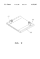
- FIG. 2 is a propective view of the present invention.
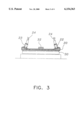
- FIG. 3 is an installed view in section of the present invention, showing the metal water container fastened to a CPU.
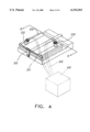
- FIG. 4 is an applied view of the present invention, showing the metal water container fastened to a CPU, the first plug and the second plug connected to a water tank.
- the present invention comprises a flat, rectangular metal water container 20, a first plug 22, a second plug 23, and a clamp 32.
- the two opposite lateral portions of the metal water container 20 have a thickness (height) greater than the middle part thereof.
- the metal water container 20 has a flat bottom sidewall. When in use, the metal water container 20 is secured in place by the clamp 32, keeping the flat bottom sidewall of the metal water container 20 in close contact with the CPU 30.
- the first plug 22 and the second plug 23 are respectively diagonally installed in the thicker lateral portions of the metal water container 20 at the top.
- a flow of water 24 is delivered from a water source through the first plug 22 into the metal water container 20, and then forced out of the metal water container 20 through the second plug 23.
- the velocity of the flow of water 24 is relatively increased due to venturi effect, enabling heat to be quickly carried away from the CPU 30 through the running flow of water 24 via the metal water container 20. Because the temperature of the flow of water 24 is lower than room temperature, it is not necessary to provide cold air to the inside of the computer, and the running flow of water 24 is sufficient to effectively quickly carry heat away from the CPU 30.
- the metal water container 20 is fastened to the CPU 30 by a clamp 32, keeping the flat bottom sidewall of the metal water container 20 in close contact with the flat top sidewall of the CPU 30, the first plug 22 and the second plug 23 are respectively connected to a water tank 40 through a respective hose 42.
- a water pump (not shown) is installed in the water tank 40 to pump water from the water tank 40 into the first plug 22, enabling the output flow of water to flow through the metal water container 20 and then to flow back to the water tank 40 through the second plug 23.
- heat is carried away with water from the CPU 30.
- the present invention can also be used to carry from any of other electronic devices that produce heat when working.
- the invention can be used to carry heat from an IC, a 3D video card, etc.
Abstract
An electronic device cooling arrangement, which includes a flat, rectangular metal water container attached to an electronic device, for example, a CPU for carrying heat away from the CPU, the metal water container having a thinner middle portion for causing a venturi effect upon flowing of water through the metal water container, a first plug installed in one thicker lateral portion of the metal water container for guiding a flow of cooling water from an external water source into the metal water container, and a second plug installed in an opposite thicker lateral portion of the metal water container remote from the first plug for guiding the intake flow of cooling water out of the metal water container for enabling heat to be carried away from the CPU with the output flow of cooling water.
Description
The present invention relates to an electronic device cooling arrangement, and more particularly to such an electronic device cooling arrangement, which uses a venturi effect to accelerate the velocity of a flow of cooling water passing through a flat metal container on an electronic device, enabling heat to be quickly carried away with the running flow of cooling water from the electronic device.
When an electronic device, for example, an IC or CPU works, it produces much heat. Heat must be quickly carried away so as not to affect normal function of the electronic device. According to tests, when the temperature of an electronic device surpasses 10° over the rated working temperature, the service life of the electronic device will be shortened by half. FIG. 1 shows a CPU cooling arrangement according to the prior art. According to this arrangement, a heat sink 12 is closely attached to the top sidewall of the CPU 14 and secured in place by clamp means, and a fan 10 is mounted on the heat sink 12 to cause currents of air, enabling heat to be quickly carried away from the CPU 14 through the heat sink 12 into the air. This CPU cooling arrangement is still not satisfactory in function. Because the heat sink and the fan are arranged in a stack and mounted on the CPU at the topside, much installation space is required. During the operation of the CPU, the temperature of the CPU may vary with the ambient temperature, and a sudden increase of temperature may cause the CPU to fail. Further, this arrangement cannot effectively carry heat away from the CPU 14 when in a poor ventilation surrounding.
The present invention has been accomplished to provide an electronic device cooling arrangement, which eliminates the aforesaid drawbacks. According to one aspect of the present invention, a flat, rectangular metal water container is used and attached to the electronic device from which heat is to be carried away, enabling heat to be quickly carried away from the electronic device with a running flow of cooling water passing through the metal water container. According to another aspect of the present invention, the metal water container has a narrower middle portion for causing a venturi effect to accelerate the flowing velocity of the running flow of cooling water passing through. According to still another aspect of the present invention, a conventional clamp is used to fix the metal water container to the electronic device from which heat is to be carried away.
FIG. 1 illustrates a CPU cooling arrangement according to the prior art.
FIG. 2 is a propective view of the present invention.
FIG. 3 is an installed view in section of the present invention, showing the metal water container fastened to a CPU.
FIG. 4 is an applied view of the present invention, showing the metal water container fastened to a CPU, the first plug and the second plug connected to a water tank.
Referring to FIGS. 2 and 3, the present invention comprises a flat, rectangular metal water container 20, a first plug 22, a second plug 23, and a clamp 32. The two opposite lateral portions of the metal water container 20 have a thickness (height) greater than the middle part thereof. The metal water container 20 has a flat bottom sidewall. When in use, the metal water container 20 is secured in place by the clamp 32, keeping the flat bottom sidewall of the metal water container 20 in close contact with the CPU 30. The first plug 22 and the second plug 23 are respectively diagonally installed in the thicker lateral portions of the metal water container 20 at the top. A flow of water 24 is delivered from a water source through the first plug 22 into the metal water container 20, and then forced out of the metal water container 20 through the second plug 23. When the flow of water 24 passing from the first plug 22 through the thinner middle portion of the metal container 20 to the second plug 22, the velocity of the flow of water 24 is relatively increased due to venturi effect, enabling heat to be quickly carried away from the CPU 30 through the running flow of water 24 via the metal water container 20. Because the temperature of the flow of water 24 is lower than room temperature, it is not necessary to provide cold air to the inside of the computer, and the running flow of water 24 is sufficient to effectively quickly carry heat away from the CPU 30.
Referring to FIG. 4, the metal water container 20 is fastened to the CPU 30 by a clamp 32, keeping the flat bottom sidewall of the metal water container 20 in close contact with the flat top sidewall of the CPU 30, the first plug 22 and the second plug 23 are respectively connected to a water tank 40 through a respective hose 42. A water pump (not shown) is installed in the water tank 40 to pump water from the water tank 40 into the first plug 22, enabling the output flow of water to flow through the metal water container 20 and then to flow back to the water tank 40 through the second plug 23. During circulation of water, heat is carried away with water from the CPU 30.
The present invention can also be used to carry from any of other electronic devices that produce heat when working. For example, the invention can be used to carry heat from an IC, a 3D video card, etc.
It is to be understood that the drawings are designed for purposes of illustration only, and are not intended for use as a definition of the limits and scope of the invention disclosed.
Claims (5)
1. An electronic device cooling arrangement comprising:
a flat, rectangular metal water container attached to an electronic device for carrying heat away from the electronic device, said metal water container having a thinner middle portion and two thicker lateral portions at two opposite lateral sides of said thinner middle portion;
a first plug installed in one thicker lateral portion of said metal water container for guiding a flow of cooling water into said metal water container; and
a second plug installed in one thicker lateral portion of said metal water container remote from said first plug for guiding intake flow of cooling water out of said metal water container.
2. The electronic device cooling arrangement of claim 1 wherein said metal water container is a copper water container.
3. The electronic device cooling arrangement of claim 1 wherein said metal water container is an aluminum water container.
4. The electronic device cooling arrangement of claim 1 further comprising clamp means for securing said metal water container to the electronic device.
5. The electronic device cooling arrangement of claim 1 further comprising a water inlet pipe means for guiding a flow of cooling water from an external water source to said first plug and said metal water container, and a water outlet pipe means for guiding the intake flow of cooling water out of said metal water container and said second plug.
Priority Applications (1)
| Application Number | Priority Date | Filing Date | Title |
|---|---|---|---|
| US09/474,252 US6154363A (en) | 1999-12-29 | 1999-12-29 | Electronic device cooling arrangement |
Applications Claiming Priority (1)
| Application Number | Priority Date | Filing Date | Title |
|---|---|---|---|
| US09/474,252 US6154363A (en) | 1999-12-29 | 1999-12-29 | Electronic device cooling arrangement |
Publications (1)
| Publication Number | Publication Date |
|---|---|
| US6154363A true US6154363A (en) | 2000-11-28 |
Family
ID=23882779
Family Applications (1)
| Application Number | Title | Priority Date | Filing Date |
|---|---|---|---|
| US09/474,252 Expired - Fee Related US6154363A (en) | 1999-12-29 | 1999-12-29 | Electronic device cooling arrangement |
Country Status (1)
| Country | Link |
|---|---|
| US (1) | US6154363A (en) |
Cited By (31)
| Publication number | Priority date | Publication date | Assignee | Title |
|---|---|---|---|---|
| US6606251B1 (en) | 2002-02-07 | 2003-08-12 | Cooligy Inc. | Power conditioning module |
| AT410881B (en) * | 2000-12-20 | 2003-08-25 | Cool Structures Production And | MICRO Heat Exchanger |
| US6622782B2 (en) * | 1999-06-14 | 2003-09-23 | Telefonaktiebolaget Lm Ericsson (Publ) | Device for cooling of electronic components |
| US6725682B2 (en) | 2001-07-13 | 2004-04-27 | Coolit Systems Inc. | Computer cooling apparatus |
| KR100456342B1 (en) * | 2002-02-08 | 2004-11-12 | 쿨랜스코리아 주식회사 | A water cooling type cooling block for semiconductor chip |
| US20050016715A1 (en) * | 2003-07-23 | 2005-01-27 | Douglas Werner | Hermetic closed loop fluid system |
| US20050039880A1 (en) * | 2001-12-26 | 2005-02-24 | Scott Alexander Robin Walter | Computer cooling apparatus |
| US20050081532A1 (en) * | 2001-07-13 | 2005-04-21 | Scott Alexander R.W. | Computer cooling apparatus |
| US20050092007A1 (en) * | 2003-10-30 | 2005-05-05 | International Business Machines Corporation | Cooling of surface temperature of a device |
| US20060065386A1 (en) * | 2004-08-31 | 2006-03-30 | Mohammed Alam | Self-actuating and regulating heat exchange system |
| US20070227698A1 (en) * | 2006-03-30 | 2007-10-04 | Conway Bruce R | Integrated fluid pump and radiator reservoir |
| EP1853099A1 (en) * | 2006-05-04 | 2007-11-07 | Bombardier Transportation GmbH | A cooling device and use thereof |
| US20080101023A1 (en) * | 2006-11-01 | 2008-05-01 | Hsia-Yuan Hsu | Negative pressure pump device |
| US7449122B2 (en) | 2002-09-23 | 2008-11-11 | Cooligy Inc. | Micro-fabricated electrokinetic pump |
| US20090114733A1 (en) * | 2007-11-07 | 2009-05-07 | Matusinec Robert D | Hydrogen fired heat exchanger |
| WO2010049710A1 (en) | 2008-10-30 | 2010-05-06 | Aqua Cooling Solutions Ltd. | An electronic system |
| US7715194B2 (en) | 2006-04-11 | 2010-05-11 | Cooligy Inc. | Methodology of cooling multiple heat sources in a personal computer through the use of multiple fluid-based heat exchanging loops coupled via modular bus-type heat exchangers |
| US20100129140A1 (en) * | 2008-11-26 | 2010-05-27 | Coolit Systems Inc. | Connector for a liquid cooling system in a computer |
| US20100127388A1 (en) * | 2008-11-25 | 2010-05-27 | Stanley Gavin D | Metal injection molded heat dissipation device |
| US7806168B2 (en) | 2002-11-01 | 2010-10-05 | Cooligy Inc | Optimal spreader system, device and method for fluid cooled micro-scaled heat exchange |
| US20110048672A1 (en) * | 2009-08-28 | 2011-03-03 | International Business Machines Corporation | Thermal ground plane for cooling a computer |
| US7913719B2 (en) | 2006-01-30 | 2011-03-29 | Cooligy Inc. | Tape-wrapped multilayer tubing and methods for making the same |
| US7991515B2 (en) | 2007-01-15 | 2011-08-02 | Coolit Systems Inc. | Computer cooling system with preferential cooling device selection |
| US20120044649A1 (en) * | 2010-08-19 | 2012-02-23 | Hon Hai Precision Industry Co., Ltd. | Heat dissipation device |
| US8157001B2 (en) | 2006-03-30 | 2012-04-17 | Cooligy Inc. | Integrated liquid to air conduction module |
| US8250877B2 (en) | 2008-03-10 | 2012-08-28 | Cooligy Inc. | Device and methodology for the removal of heat from an equipment rack by means of heat exchangers mounted to a door |
| US8254422B2 (en) | 2008-08-05 | 2012-08-28 | Cooligy Inc. | Microheat exchanger for laser diode cooling |
| US8602092B2 (en) | 2003-07-23 | 2013-12-10 | Cooligy, Inc. | Pump and fan control concepts in a cooling system |
| USD749713S1 (en) * | 2014-07-31 | 2016-02-16 | Innovative Medical Equipment, Llc | Heat exchanger |
| US9297571B1 (en) | 2008-03-10 | 2016-03-29 | Liebert Corporation | Device and methodology for the removal of heat from an equipment rack by means of heat exchangers mounted to a door |
| US20170229377A1 (en) * | 2016-02-04 | 2017-08-10 | International Business Machines Corporation | Liquid manifold structure for direct cooling of lidded electronics modules |
Citations (10)
| Publication number | Priority date | Publication date | Assignee | Title |
|---|---|---|---|---|
| US3481393A (en) * | 1968-01-15 | 1969-12-02 | Ibm | Modular cooling system |
| US4072188A (en) * | 1975-07-02 | 1978-02-07 | Honeywell Information Systems Inc. | Fluid cooling systems for electronic systems |
| JPH03159160A (en) * | 1989-11-16 | 1991-07-09 | Nec Commun Syst Ltd | Cooling structure of electronic device |
| US5089936A (en) * | 1988-09-09 | 1992-02-18 | Hitachi, Ltd. | Semiconductor module |
| US5249100A (en) * | 1989-05-19 | 1993-09-28 | Hitachi, Ltd. | Electronic circuit device provided with a ceramic substrate having lead pins bonded thereto by solder |
| US5365402A (en) * | 1990-11-30 | 1994-11-15 | Hitachi, Ltd. | Cooling apparatus of electronic device |
| US5457342A (en) * | 1994-03-30 | 1995-10-10 | Herbst, Ii; Gerhardt G. | Integrated circuit cooling apparatus |
| US5640303A (en) * | 1995-10-30 | 1997-06-17 | Precision Connector Designs, Inc. | Interconnection apparatus for semiconductor/integrated circuit devices |
| US5731954A (en) * | 1996-08-22 | 1998-03-24 | Cheon; Kioan | Cooling system for computer |
| US5870823A (en) * | 1996-11-27 | 1999-02-16 | International Business Machines Corporation | Method of forming a multilayer electronic packaging substrate with integral cooling channels |
-
1999
- 1999-12-29 US US09/474,252 patent/US6154363A/en not_active Expired - Fee Related
Patent Citations (10)
| Publication number | Priority date | Publication date | Assignee | Title |
|---|---|---|---|---|
| US3481393A (en) * | 1968-01-15 | 1969-12-02 | Ibm | Modular cooling system |
| US4072188A (en) * | 1975-07-02 | 1978-02-07 | Honeywell Information Systems Inc. | Fluid cooling systems for electronic systems |
| US5089936A (en) * | 1988-09-09 | 1992-02-18 | Hitachi, Ltd. | Semiconductor module |
| US5249100A (en) * | 1989-05-19 | 1993-09-28 | Hitachi, Ltd. | Electronic circuit device provided with a ceramic substrate having lead pins bonded thereto by solder |
| JPH03159160A (en) * | 1989-11-16 | 1991-07-09 | Nec Commun Syst Ltd | Cooling structure of electronic device |
| US5365402A (en) * | 1990-11-30 | 1994-11-15 | Hitachi, Ltd. | Cooling apparatus of electronic device |
| US5457342A (en) * | 1994-03-30 | 1995-10-10 | Herbst, Ii; Gerhardt G. | Integrated circuit cooling apparatus |
| US5640303A (en) * | 1995-10-30 | 1997-06-17 | Precision Connector Designs, Inc. | Interconnection apparatus for semiconductor/integrated circuit devices |
| US5731954A (en) * | 1996-08-22 | 1998-03-24 | Cheon; Kioan | Cooling system for computer |
| US5870823A (en) * | 1996-11-27 | 1999-02-16 | International Business Machines Corporation | Method of forming a multilayer electronic packaging substrate with integral cooling channels |
Cited By (50)
| Publication number | Priority date | Publication date | Assignee | Title |
|---|---|---|---|---|
| US6622782B2 (en) * | 1999-06-14 | 2003-09-23 | Telefonaktiebolaget Lm Ericsson (Publ) | Device for cooling of electronic components |
| AT410881B (en) * | 2000-12-20 | 2003-08-25 | Cool Structures Production And | MICRO Heat Exchanger |
| US7174738B2 (en) | 2001-07-13 | 2007-02-13 | Coolit Systems Inc. | Computer cooling apparatus |
| US6725682B2 (en) | 2001-07-13 | 2004-04-27 | Coolit Systems Inc. | Computer cooling apparatus |
| US20050081532A1 (en) * | 2001-07-13 | 2005-04-21 | Scott Alexander R.W. | Computer cooling apparatus |
| US20080041566A1 (en) * | 2001-07-13 | 2008-02-21 | Coolit Systems Inc. | Computer Cooling Apparatus |
| US7739883B2 (en) | 2001-07-13 | 2010-06-22 | Coolit Systems Inc. | Computer cooling apparatus |
| US20050039880A1 (en) * | 2001-12-26 | 2005-02-24 | Scott Alexander Robin Walter | Computer cooling apparatus |
| US6678168B2 (en) | 2002-02-07 | 2004-01-13 | Cooligy, Inc. | System including power conditioning modules |
| US6606251B1 (en) | 2002-02-07 | 2003-08-12 | Cooligy Inc. | Power conditioning module |
| KR100456342B1 (en) * | 2002-02-08 | 2004-11-12 | 쿨랜스코리아 주식회사 | A water cooling type cooling block for semiconductor chip |
| US7449122B2 (en) | 2002-09-23 | 2008-11-11 | Cooligy Inc. | Micro-fabricated electrokinetic pump |
| US7806168B2 (en) | 2002-11-01 | 2010-10-05 | Cooligy Inc | Optimal spreader system, device and method for fluid cooled micro-scaled heat exchange |
| US7021369B2 (en) | 2003-07-23 | 2006-04-04 | Cooligy, Inc. | Hermetic closed loop fluid system |
| US8602092B2 (en) | 2003-07-23 | 2013-12-10 | Cooligy, Inc. | Pump and fan control concepts in a cooling system |
| US20050016715A1 (en) * | 2003-07-23 | 2005-01-27 | Douglas Werner | Hermetic closed loop fluid system |
| US6943444B2 (en) * | 2003-10-30 | 2005-09-13 | International Business Machines Corporation | Cooling of surface temperature of a device |
| US20050092007A1 (en) * | 2003-10-30 | 2005-05-05 | International Business Machines Corporation | Cooling of surface temperature of a device |
| US20060065386A1 (en) * | 2004-08-31 | 2006-03-30 | Mohammed Alam | Self-actuating and regulating heat exchange system |
| US7913719B2 (en) | 2006-01-30 | 2011-03-29 | Cooligy Inc. | Tape-wrapped multilayer tubing and methods for making the same |
| US20070227698A1 (en) * | 2006-03-30 | 2007-10-04 | Conway Bruce R | Integrated fluid pump and radiator reservoir |
| US8157001B2 (en) | 2006-03-30 | 2012-04-17 | Cooligy Inc. | Integrated liquid to air conduction module |
| US7715194B2 (en) | 2006-04-11 | 2010-05-11 | Cooligy Inc. | Methodology of cooling multiple heat sources in a personal computer through the use of multiple fluid-based heat exchanging loops coupled via modular bus-type heat exchangers |
| WO2007128773A1 (en) * | 2006-05-04 | 2007-11-15 | Bombardier Transportation Gmbh | A cooling device and use thereof |
| EP1853099A1 (en) * | 2006-05-04 | 2007-11-07 | Bombardier Transportation GmbH | A cooling device and use thereof |
| US20080101023A1 (en) * | 2006-11-01 | 2008-05-01 | Hsia-Yuan Hsu | Negative pressure pump device |
| US7991515B2 (en) | 2007-01-15 | 2011-08-02 | Coolit Systems Inc. | Computer cooling system with preferential cooling device selection |
| US20090114733A1 (en) * | 2007-11-07 | 2009-05-07 | Matusinec Robert D | Hydrogen fired heat exchanger |
| US9297571B1 (en) | 2008-03-10 | 2016-03-29 | Liebert Corporation | Device and methodology for the removal of heat from an equipment rack by means of heat exchangers mounted to a door |
| US8250877B2 (en) | 2008-03-10 | 2012-08-28 | Cooligy Inc. | Device and methodology for the removal of heat from an equipment rack by means of heat exchangers mounted to a door |
| US8254422B2 (en) | 2008-08-05 | 2012-08-28 | Cooligy Inc. | Microheat exchanger for laser diode cooling |
| US8299604B2 (en) | 2008-08-05 | 2012-10-30 | Cooligy Inc. | Bonded metal and ceramic plates for thermal management of optical and electronic devices |
| GB2465140B (en) * | 2008-10-30 | 2011-04-13 | Aqua Cooling Solutions Ltd | An electronic system |
| US20110226446A1 (en) * | 2008-10-30 | 2011-09-22 | Aqua Cooling Solutions Ltd. | Electronic system |
| WO2010049710A1 (en) | 2008-10-30 | 2010-05-06 | Aqua Cooling Solutions Ltd. | An electronic system |
| US8582295B2 (en) | 2008-10-30 | 2013-11-12 | Aqua Cooling Solutions Ltd. | Electronic system |
| GB2465140A (en) * | 2008-10-30 | 2010-05-12 | Aqua Cooling Solutions Ltd | Heat exchange apparatus for an electronic or computer system |
| EA019644B1 (en) * | 2008-10-30 | 2014-05-30 | Аква Кулинг Солушнз Лтд. | Heat exchanger for cooling an electronic device |
| US9288933B2 (en) | 2008-11-25 | 2016-03-15 | Intel Corporation | Metal injection molded heat dissipation device |
| US20100127388A1 (en) * | 2008-11-25 | 2010-05-27 | Stanley Gavin D | Metal injection molded heat dissipation device |
| US8259451B2 (en) * | 2008-11-25 | 2012-09-04 | Intel Corporation | Metal injection molded heat dissipation device |
| US8889489B2 (en) | 2008-11-25 | 2014-11-18 | Intel Corporation | Metal injection molded heat dissipation device |
| US20100129140A1 (en) * | 2008-11-26 | 2010-05-27 | Coolit Systems Inc. | Connector for a liquid cooling system in a computer |
| US8776868B2 (en) * | 2009-08-28 | 2014-07-15 | International Business Machines Corporation | Thermal ground plane for cooling a computer |
| US20110048672A1 (en) * | 2009-08-28 | 2011-03-03 | International Business Machines Corporation | Thermal ground plane for cooling a computer |
| US9377251B2 (en) | 2009-08-28 | 2016-06-28 | Globalfoundries Inc. | Thermal ground plane for cooling a computer |
| US8363405B2 (en) * | 2010-08-19 | 2013-01-29 | Hon Hai Precision Industry Co., Ltd. | Heat dissipation device |
| US20120044649A1 (en) * | 2010-08-19 | 2012-02-23 | Hon Hai Precision Industry Co., Ltd. | Heat dissipation device |
| USD749713S1 (en) * | 2014-07-31 | 2016-02-16 | Innovative Medical Equipment, Llc | Heat exchanger |
| US20170229377A1 (en) * | 2016-02-04 | 2017-08-10 | International Business Machines Corporation | Liquid manifold structure for direct cooling of lidded electronics modules |
Similar Documents
| Publication | Publication Date | Title |
|---|---|---|
| US6154363A (en) | Electronic device cooling arrangement | |
| US6324058B1 (en) | Heat-dissipating apparatus for an integrated circuit device | |
| US20190090384A1 (en) | Pipeless liquid-cooled heat dissipation system | |
| US6219236B1 (en) | Cooling system for multichip module | |
| US6955212B1 (en) | Water-cooler radiator module | |
| US20050082666A1 (en) | Liquid cooling device | |
| US6234240B1 (en) | Fanless cooling system for computer | |
| US20040165355A1 (en) | CPU cooling structure | |
| US7143815B2 (en) | Liquid cooling device | |
| KR100310099B1 (en) | Radiating device for semiconductor integrated circuit device and portable computer having same | |
| US7472743B2 (en) | Liquid cooling system suitable for removing heat from electronic components | |
| US6343478B1 (en) | Water/air dual cooling arrangement for a CPU | |
| US7133284B2 (en) | Power supply without cooling fan | |
| US7852630B2 (en) | Heat dissipating device | |
| US6560104B2 (en) | Portable computer and docking station cooling | |
| US20080158820A1 (en) | Heat dissipation device for computer add-on cards | |
| US7352577B2 (en) | Liquid-cooled heat dissipation module | |
| JP2002151638A (en) | Cooler for electronic equipment | |
| CN101026944A (en) | Radiating device | |
| US20150049436A1 (en) | Heat dissipation device for electronic ballast | |
| US6822862B2 (en) | Apparatus and method for heat sink | |
| US7038911B2 (en) | Push-pull dual fan fansink | |
| US20080117595A1 (en) | Operating Housing | |
| JPH08222672A (en) | Cooling structure for semiconductor module | |
| USRE40369E1 (en) | Heat sink and electronic device employing the same |
Legal Events
| Date | Code | Title | Description |
|---|---|---|---|
| REMI | Maintenance fee reminder mailed | ||
| LAPS | Lapse for failure to pay maintenance fees | ||
| STCH | Information on status: patent discontinuation |
Free format text: PATENT EXPIRED DUE TO NONPAYMENT OF MAINTENANCE FEES UNDER 37 CFR 1.362 |
|
| FP | Lapsed due to failure to pay maintenance fee |
Effective date: 20041128 |