US6152666A - Screw for use as a fastener in fibrous material such as wood - Google Patents
Screw for use as a fastener in fibrous material such as wood Download PDFInfo
- Publication number
- US6152666A US6152666A US09/268,790 US26879099A US6152666A US 6152666 A US6152666 A US 6152666A US 26879099 A US26879099 A US 26879099A US 6152666 A US6152666 A US 6152666A
- Authority
- US
- United States
- Prior art keywords
- screw
- thread
- shaped cutout
- shank
- edge
- Prior art date
- Legal status (The legal status is an assumption and is not a legal conclusion. Google has not performed a legal analysis and makes no representation as to the accuracy of the status listed.)
- Expired - Lifetime
Links
- 239000002023 wood Substances 0.000 title claims abstract description 8
- 239000002657 fibrous material Substances 0.000 title claims description 7
- 230000001154 acute effect Effects 0.000 claims description 4
- 239000011800 void material Substances 0.000 claims description 2
- 230000008901 benefit Effects 0.000 description 4
- 230000007423 decrease Effects 0.000 description 2
- 230000002093 peripheral effect Effects 0.000 description 2
- 238000009434 installation Methods 0.000 description 1
- 230000001788 irregular Effects 0.000 description 1
- 230000004048 modification Effects 0.000 description 1
- 238000012986 modification Methods 0.000 description 1
- 238000010079 rubber tapping Methods 0.000 description 1
- 230000007704 transition Effects 0.000 description 1
Images
Classifications
-
- F—MECHANICAL ENGINEERING; LIGHTING; HEATING; WEAPONS; BLASTING
- F16—ENGINEERING ELEMENTS AND UNITS; GENERAL MEASURES FOR PRODUCING AND MAINTAINING EFFECTIVE FUNCTIONING OF MACHINES OR INSTALLATIONS; THERMAL INSULATION IN GENERAL
- F16B—DEVICES FOR FASTENING OR SECURING CONSTRUCTIONAL ELEMENTS OR MACHINE PARTS TOGETHER, e.g. NAILS, BOLTS, CIRCLIPS, CLAMPS, CLIPS OR WEDGES; JOINTS OR JOINTING
- F16B25/00—Screws that cut thread in the body into which they are screwed, e.g. wood screws
- F16B25/001—Screws that cut thread in the body into which they are screwed, e.g. wood screws characterised by the material of the body into which the screw is screwed
- F16B25/0015—Screws that cut thread in the body into which they are screwed, e.g. wood screws characterised by the material of the body into which the screw is screwed the material being a soft organic material, e.g. wood or plastic
-
- F—MECHANICAL ENGINEERING; LIGHTING; HEATING; WEAPONS; BLASTING
- F16—ENGINEERING ELEMENTS AND UNITS; GENERAL MEASURES FOR PRODUCING AND MAINTAINING EFFECTIVE FUNCTIONING OF MACHINES OR INSTALLATIONS; THERMAL INSULATION IN GENERAL
- F16B—DEVICES FOR FASTENING OR SECURING CONSTRUCTIONAL ELEMENTS OR MACHINE PARTS TOGETHER, e.g. NAILS, BOLTS, CIRCLIPS, CLAMPS, CLIPS OR WEDGES; JOINTS OR JOINTING
- F16B25/00—Screws that cut thread in the body into which they are screwed, e.g. wood screws
- F16B25/0036—Screws that cut thread in the body into which they are screwed, e.g. wood screws characterised by geometric details of the screw
- F16B25/0042—Screws that cut thread in the body into which they are screwed, e.g. wood screws characterised by geometric details of the screw characterised by the geometry of the thread, the thread being a ridge wrapped around the shaft of the screw
- F16B25/0052—Screws that cut thread in the body into which they are screwed, e.g. wood screws characterised by geometric details of the screw characterised by the geometry of the thread, the thread being a ridge wrapped around the shaft of the screw the ridge having indentations, notches or the like in order to improve the cutting behaviour
-
- F—MECHANICAL ENGINEERING; LIGHTING; HEATING; WEAPONS; BLASTING
- F16—ENGINEERING ELEMENTS AND UNITS; GENERAL MEASURES FOR PRODUCING AND MAINTAINING EFFECTIVE FUNCTIONING OF MACHINES OR INSTALLATIONS; THERMAL INSULATION IN GENERAL
- F16B—DEVICES FOR FASTENING OR SECURING CONSTRUCTIONAL ELEMENTS OR MACHINE PARTS TOGETHER, e.g. NAILS, BOLTS, CIRCLIPS, CLAMPS, CLIPS OR WEDGES; JOINTS OR JOINTING
- F16B35/00—Screw-bolts; Stay-bolts; Screw-threaded studs; Screws; Set screws
- F16B35/04—Screw-bolts; Stay-bolts; Screw-threaded studs; Screws; Set screws with specially-shaped head or shaft in order to fix the bolt on or in an object
- F16B35/041—Specially-shaped shafts
- F16B35/048—Specially-shaped necks
Definitions
- This invention relates to woodscrews or the like type of screws for use in fibrous material such as wood, particularly the self tapping screws.
- Such screws are typically provided with a smooth, continuous thread.
- This arrangement is satisfactory where the density of the workpiece of fibrous material is relatively low or where a pilot hole is provided.
- a high torque may be required to drive the screw fully into the workpiece. It is not uncommon, particularly with the use of a power screwdriver, that the high torque requirement results in breakage of the screw. The splitting of the workpiece may also occur.
- UK Patent Specification 1,120,991 describes a wood screw wherein the thread on the shank is provided with grooves extending helically for substantially the full length of the threaded portion. Thus the thread is transformed into a number of radially outwardly projecting protuberances.
- the drawback is in a substantially weakened overall torque strength of the screw and are thus prone to breakage particularly when used with a power screwdriver. Also, the cutouts do not provide sufficient space for debris formed by the cutting edge of the respective cutout. The cutouts at the tip hamper the guidance of the screw at the introduction into the workpiece.
- the cutouts are each comprised of a pair of closely spaced V-shaped cutout section which provide about three W-shaped cutouts about a single convolute of the thread in the limited portion.
- the limited portion of the thread is an intermediate portion disposed axially between the first end or tip and the second end or head end portion of the thread which are both devoid of the cutouts.
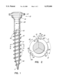
- FIG. 1 is a side view of a screw of the present invention
- FIG. 2 is a diagrammatic sectional view taken along a section line II--II of FIG. 1 and showing one turn or convolute of the thread in a flattened-out condition to indicate the preferred distribution of the cutouts and their depth;
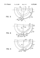
- FIG. 3 is a partial, view corresponding to FIG. 2 and showing the geometry of the cutout of another embodiment of the invention
- FIG. 4 is a view similar to that of FIG. 3 and showing the geometry of the cutout of yet another embodiment of the present invention.
- FIG. 5 is a view similar to that of FIG. 3 and showing the geometry the cutout of a further embodiment of the present invention.
- FIG. 1 represents an exemplary type of a woodscrew to which the present invention has been applied.
- the screw is integrally formed and comprises a cylindric shank portion 10 defining, at a first end, a tapering tip portion 11.
- the opposite, second end of the shank portion 10 merges with a head end portion 12.
- the head end portion has a somewhat increased diameter to provide a smooth transition to a head 13, for instance, by a frustoconical transitional section 14.
- a helical thread 15 extends from the tapering tip 11 to a point spaced from the head 13.
- Reference number 25 designates the direction of turning the screw to drive same into a workpiece.
- the embodiment shown is a screw having the length of about 250 mm.
- the shank 10 has a total of ten convolutes or turns, it being understood that the number of the turns is optional. Proceeding from the tip 11, there is a first thread portion having about two turns 16 which are continuous and are devoid of the cutouts. The next, intermediate, limited thread portion, includes about five turns 17 and, finally, near the second end or head end portion 12, there are about four turns 18 of the third thread portion.
- Each turn 17 of the limited portion is provided with radially inwardly directed cutouts (FIG. 2) 19, 20, 21.
- the cutouts of the first, preferred embodiment of the invention will now be described in greater detail. For simplicity, only one cutout is described 19 with reference to FIG. 2, it being understood that it is preferred that the remaining cutouts 20, 21 be of the same shape, as shown in FIG. 2.
- the cutouts 19, 20, 21 are spaced from each other at an angle ⁇ of about 120° which provides the density of about three cutouts per each convolute 17.
- Each cutout, e.g. cutout 19, is comprised of a pair of closely spaced V-shaped or triangular, radially inwardly narrowing cutout sections 22, 23 whereby the cutout 19 has the general configuration of the letter W, defining a central tooth 24. It can be seen from the drawings that the radial depth of each cutout 19, 20, 21 is smaller than the width of the thread at the turn 17.
- the recommended minimum length of the shank of the screw to fully benefit from the present invention is about 30 mm (11/4").
- the number of threads 17, of the limited, intermediate portion is preferably selected in dependence on the overall length of the stem of the screw. For instance, screws with shanks 30 mm to 140 mm long, should have about 3 turns of threads 17 with the cutouts. Those with shank length of about 150 to about 240 mm are preferably provided with four turns of threads 17 and those over 250 mm preferably have 5 turns of threads 17. As mentioned above, the threads 17 have each three cutouts 19-21 at an equidistant arcuate spacing.
- the cutout section 22 When viewed from the standpoint of rotation in the direction 25, the cutout section 22 is a front cutout section and the cutout section 23 is a rear cutout section.
- the cutout sections 22, 23 of the embodiment in FIG. 2 are so arranged and disposed that the tooth 24 has the shape of a trapezoid.
- the front cutout section 22 has a forward edge 26 and a back edge 27.
- the rear cutout section 23 has a forward edge 28 and a back edge 29.
- the back edge 27 defines a cutting edge of the tooth 24 and the forward edge 28 defines a trailing edge of the tooth 24.
- the cutout sections 22, 23 of each cutout define a void before and after the tooth 24, for debris generated by the tooth of the same cutout 19 or of the preceding cutout 21.
- the combined width of the three cutouts 19-21 measured peripherally at the crest of the thread 17 is about one-third of the circumference of one convolute of the thread.
- each cutout section 22, 23 is so disposed that the radially inner angle a between the respective forward edge 26, 28 and back edge 27, 29 is about 90°. This relationship is not present in further, exemplary embodiments as will now be described with reference to FIGS. 3-5 where the same reference numbers have been used to designate the corresponding elements of the screw.
- the radially inner angle between the forward edge 26 and the back edge 27 is an acute angle.
- the disposition of the edges 26 and 27 is such that the back edge 27, i.e., the cutting edge 27 of the tooth 24, is on a line 30 tangent to a first reference circle 31 concentric with the axis of the shank portion 10.
- the edge 26, however, is on a line 32 tangent to a second reference circle 33.
- the diameter of the reference circle 31 is smaller than that of the reference circle 33.
- the cutting edge 27 in FIG. 3 is radially steeper with respect to the centre of the shank portion 10 than in FIG. 2.
- the rear cutout section 23 is a mirror image of the front cutout section 22.
- the radial steepness of the cutting edge 27 increases with the decrease of the diameter of the reference circle 31 and decreases with the enlargement of such diameter.
- the maximum radial steepness is the steepness where the diameter of the first reference circle is zero, i.e. it is the centre of the shank.
- the overall peripheral width of this embodiment is substantially smaller than about one-third of the circumference of one turn 17 of the thread, to provide a good pullout resistance while retaining the advantage of having two voids for the debris made by each tooth 24.
- the cutout sections 22, 23 are not mirror images of each other as in FIGS. 2 and 3. Instead, they have identical contour.
- the line 30 of the cutting edge 27 of the tooth 24 displays a maximum degree of radial steepness since the line 30 passes through the centre (31) of the shank portion 10.
- the reference circle 30 has a zero diameter and is the centre of the shank.
- the cutting edge 27 extends exactly radially.
- the forward edge 26 of the recess 22 is tangent to the second reference circle 33.
- the forward and the back edges 28, 29 of the rear cutout section 23 are arranged in the same order as the edges 26, 27 of the front cutout section 22.
- the line 34 of the forward edge 28 of the cutout section 23 is a tangent to the reference circle 33, while the back edge is radial.
- the angle, corresponding to angle ⁇ of FIG. 2, of both V-shaped recesses of FIG. 4 is an acute angle, in the embodiment shown, about 45°.
- This embodiment presents a further reduction of the peripheral width of the cutout 19.
- the tooth 24 has the contour of an irregular trapezoid.
- FIG. 5 is similar to that of FIG. 4 with respect to the angles of the forward and back edges 26, 27, 28, 29 but the overall width of the tooth 24 and if the overall cutout 19 is smaller. This results in a triangular shape of the tooth 24 and in a smaller overall width of the cutout 19.
- the width of the cutout of the embodiment of FIG. 5 is the smallest of those shown while sufficient space is still provided for fibrous debris.
- the screw of the present invention is intended mainly for woodscrews or the like having the length of about one inch or more.
- the screw of the invention has the advantage of a reduced resistance to the driving force when the screw is driven into a workpiece. It has been found that the invention achieves reduction of the torque required by about 30% over known woodscrews. This reduces and in many cases eliminates the occurrence of breakages of the shanks of power driven screws of the present invention. While the drive-in torque stress is reduced, once the screw is in place, it does not have the tendency to become loose.
Abstract
Description
Claims (18)
Applications Claiming Priority (2)
| Application Number | Priority Date | Filing Date | Title |
|---|---|---|---|
| CA002234040A CA2234040A1 (en) | 1998-04-03 | 1998-04-03 | Screw for use as a fastener in fibrous material such as wood |
| CA2234040 | 1998-04-03 |
Publications (1)
| Publication Number | Publication Date |
|---|---|
| US6152666A true US6152666A (en) | 2000-11-28 |
Family
ID=4162294
Family Applications (1)
| Application Number | Title | Priority Date | Filing Date |
|---|---|---|---|
| US09/268,790 Expired - Lifetime US6152666A (en) | 1998-04-03 | 1999-03-16 | Screw for use as a fastener in fibrous material such as wood |
Country Status (10)
| Country | Link |
|---|---|
| US (1) | US6152666A (en) |
| EP (1) | EP0947715B1 (en) |
| JP (1) | JP4237862B2 (en) |
| CN (1) | CN1188608C (en) |
| AT (1) | ATE234432T1 (en) |
| CA (1) | CA2234040A1 (en) |
| DE (1) | DE69905783T2 (en) |
| ES (1) | ES2190626T3 (en) |
| HK (1) | HK1020604A1 (en) |
| TW (1) | TW411383B (en) |
Cited By (35)
| Publication number | Priority date | Publication date | Assignee | Title |
|---|---|---|---|---|
| US20030143058A1 (en) * | 2002-01-31 | 2003-07-31 | Honda Giken Kogyo Kabushiki Kaisha | Self tapping bolt |
| US20030185649A1 (en) * | 2002-03-27 | 2003-10-02 | Aoyama Seisakusho Co., Ltd. | Male screw part |
| US20040101381A1 (en) * | 2001-07-31 | 2004-05-27 | Illinois Tool Works Inc. | Threaded fastener for use within multiple substrates |
| US20040127297A1 (en) * | 2002-12-30 | 2004-07-01 | Barun Majumdar | Standard threaded torque fastener with novel indentation patterns to enhance torque and self-locking capabilities |
| US20050079031A1 (en) * | 2003-10-09 | 2005-04-14 | Aoyama Seisakusho Co., Ltd. | Tapping screw |
| US20050175432A1 (en) * | 2004-02-09 | 2005-08-11 | Kuo-Tai Su | Screw |
| US20050180840A1 (en) * | 2002-06-21 | 2005-08-18 | Robert Brewer | Fluid connector |
| US20060039775A1 (en) * | 2002-10-02 | 2006-02-23 | Hiromichi Mizuno | Tapping screw |
| US20060147295A1 (en) * | 2005-01-05 | 2006-07-06 | Pei-Hua Chen | Screw with two types of threads |
| US20060285940A1 (en) * | 2005-06-16 | 2006-12-21 | Mirco Walther | Screw For Use In Concrete |
| US20070065255A1 (en) * | 2005-09-21 | 2007-03-22 | A-Stainless International Co., Ltd. | Thread section for screws |
| US20070172333A1 (en) * | 2006-01-09 | 2007-07-26 | Tian-Fu Tsau | Screw member having two different thread angles formed on a sharp-edged thread |
| US20070297873A1 (en) * | 2006-06-02 | 2007-12-27 | Juergen Wieser | Thread-tapping screw |
| US7798756B2 (en) * | 2007-03-24 | 2010-09-21 | Essence Method Refine Co., Ltd. | Screw with waved thread |
| US20110176888A1 (en) * | 2010-01-20 | 2011-07-21 | Powers Fasteners, Inc. | Masonry anchor |
| US20160032956A1 (en) * | 2014-07-31 | 2016-02-04 | King Point Enterprise Co., Ltd. | Fastening bolt for use in concrete |
| US9581183B2 (en) | 2015-02-17 | 2017-02-28 | The Hillman Group, Inc. | Screw-type fastener |
| US20170360479A1 (en) * | 2014-07-03 | 2017-12-21 | Stryker European Holdings I, Llc | Conical end cap for intramedullary nail |
| USD823102S1 (en) * | 2016-08-31 | 2018-07-17 | Illinois Tool Works Inc. | Screw fastener |
| USD828149S1 (en) * | 2016-11-30 | 2018-09-11 | Hyundai Motor Company | Bolt |
| USD828148S1 (en) * | 2016-08-31 | 2018-09-11 | Illinois Tool Works Inc. | Screw fastener |
| USD845118S1 (en) * | 2017-04-20 | 2019-04-09 | A-Stainless International Co., Ltd. | Screw |
| USD854404S1 (en) * | 2017-06-16 | 2019-07-23 | Masterpiece Hardware Industrial Co., Ltd. | Screw |
| US10436238B2 (en) | 2016-04-04 | 2019-10-08 | The Hillman Group, Inc. | Screw type fastener |
| USD863050S1 (en) * | 2017-04-19 | 2019-10-15 | Ying-Chin CHAO | Screw |
| US20200102980A1 (en) * | 2018-09-28 | 2020-04-02 | Kuo-Tai Hsu | Wood screw |
| USD898196S1 (en) | 2017-07-10 | 2020-10-06 | Stryker European Holdings I, Llc | Spinal fastener with serrated thread |
| US10982703B2 (en) | 2018-04-09 | 2021-04-20 | The Hillman Group, Inc. | Screw-type fastener for concrete and hurricane resistance applications |
| US11105361B2 (en) | 2017-11-03 | 2021-08-31 | The Hillman Group, Inc. | Screw-type fastener |
| US11253060B2 (en) | 2018-10-31 | 2022-02-22 | American Woodmark Corporation | Modular enclosure system |
| US11389205B2 (en) | 2016-11-30 | 2022-07-19 | Stryker European Operations Holdings Llc | Spinal fastener with serrated thread |
| US11419652B2 (en) * | 2019-04-26 | 2022-08-23 | Warsaw Orthopedic, Inc. | Thread form for bone screw |
| US20220316514A1 (en) * | 2021-03-30 | 2022-10-06 | The Hillman Group, Inc. | Structural screw |
| USD1013498S1 (en) | 2021-02-03 | 2024-02-06 | Illinois Tool Works Inc. | Fastener |
| USD1017352S1 (en) | 2020-11-26 | 2024-03-12 | Illinois Tool Works Inc. | Fastener |
Families Citing this family (10)
| Publication number | Priority date | Publication date | Assignee | Title |
|---|---|---|---|---|
| KR20030043160A (en) * | 2001-11-27 | 2003-06-02 | 김중배 | A screw for fixing plastic |
| DE202004002877U1 (en) * | 2004-02-25 | 2005-06-30 | A-Z Ausrüstung Und Zubehör Gmbh & Co. Kg | Thread forming screw |
| DE102004021484B4 (en) * | 2004-04-30 | 2018-11-29 | Böllhoff Verbindungstechnik GmbH | Method for producing a connection arrangement |
| DE102004058812B4 (en) * | 2004-12-07 | 2006-09-28 | Institut für Holztechnologie Dresden gGmbH | Tool for creating cavities in materials, preferably sandwich panels |
| KR101722335B1 (en) * | 2015-10-23 | 2017-04-11 | 서동인 | Manufacturing method of the wood screw |
| TWM519685U (en) * | 2015-12-21 | 2016-04-01 | Shin Chun Entpr Co Ltd | Locking fastener |
| US11199056B2 (en) * | 2019-02-06 | 2021-12-14 | James Jing Yao | Threaded coupling for percussion drill bit |
| CN112727892B (en) * | 2020-12-28 | 2023-03-28 | 河北中车陆星防松技术有限公司 | Anti-backspin nut and manufacturing tool and method |
| CN112747025B (en) * | 2020-12-28 | 2023-05-09 | 江西海威智能装备有限公司 | Anti-backspin screw, manufacturing tool and manufacturing method |
| CN112727889B (en) * | 2020-12-28 | 2023-07-14 | 福建省华盖机械制造有限公司 | Anti-convolution screw and nut combination |
Citations (19)
| Publication number | Priority date | Publication date | Assignee | Title |
|---|---|---|---|---|
| FR385906A (en) * | 1908-01-03 | 1908-05-30 | Walter Christopher Jordan | Improvements to screws |
| GB667051A (en) * | 1949-09-16 | 1952-02-20 | Gkn Group Services Ltd | Improvements in or relating to self-tapping screws |
| US3314898A (en) * | 1962-03-31 | 1967-04-18 | Zh Nihon Kagaku Seni Kenkyusho | Polymerization of tetrahydrofuran |
| GB1120991A (en) * | 1965-02-02 | 1968-07-24 | G K N Screws And Fasteners Ltd | Improvements relating to wood screws |
| US3937119A (en) * | 1974-12-23 | 1976-02-10 | Illinois Tool Works, Inc. | Masonry anchor device |
| US3982575A (en) * | 1974-12-23 | 1976-09-28 | Standard Pressed Steel Co. | Thread forming self-locking screw |
| DE2815247A1 (en) * | 1978-04-08 | 1979-10-11 | Fischer Artur Dr H C | Masonry bolt with drill tip - has cutting edge on radial projection of pilot shank to enlarge hole |
| US4842467A (en) * | 1984-08-24 | 1989-06-27 | Yamashina Seiko-Sho, Ltd. | Concrete screw |
| US4973210A (en) * | 1988-08-20 | 1990-11-27 | Emhart Industries, Inc. | Anchors for fixing to dense concrete, masonry and the like |
| US5044853A (en) * | 1989-04-25 | 1991-09-03 | Erwin Rommel | Thread-cutting screw |
| US5064323A (en) * | 1990-02-28 | 1991-11-12 | Tappex Thread Inserts Limited | Self-threading fastener |
| US5110245A (en) * | 1989-09-13 | 1992-05-05 | Nitto Seiko Co., Ltd. | Thread forming screw |
| US5267423A (en) * | 1987-08-03 | 1993-12-07 | Giannuzzi Louis | Self-drilling anchor and bearing plate assembly |
| US5340254A (en) * | 1992-01-31 | 1994-08-23 | Textron Inc. | Thread forming screw for forming an internal thread in a low ductility material |
| DE29504559U1 (en) * | 1995-03-17 | 1996-02-15 | Sawatzki Guenter | Self-drilling screw |
| US5674035A (en) * | 1993-05-04 | 1997-10-07 | Ludwig Hettich Schraubenfabrik Gmbh & Co. | Thread forming screw |
| US5827030A (en) * | 1995-09-06 | 1998-10-27 | A-Z Ausrustung Und Zubehor Gmbh & Co., Kg | Thread forming joining elements |
| US5833415A (en) * | 1992-09-22 | 1998-11-10 | Titan Technology, Inc. | Anchor insert improvement |
| US5897280A (en) * | 1997-04-03 | 1999-04-27 | A-Z Ausrustung Und Zubehor Gmbh & Co. Kg | Self perforating and thread forming connecting element |
Family Cites Families (1)
| Publication number | Priority date | Publication date | Assignee | Title |
|---|---|---|---|---|
| US3472119A (en) * | 1966-06-29 | 1969-10-14 | Hubbell Inc Harvey | Thread forming screw and method of making same |
-
1998
- 1998-04-03 CA CA002234040A patent/CA2234040A1/en not_active Abandoned
- 1998-12-08 TW TW087120345A patent/TW411383B/en not_active IP Right Cessation
-
1999
- 1999-03-16 US US09/268,790 patent/US6152666A/en not_active Expired - Lifetime
- 1999-03-30 AT AT99106524T patent/ATE234432T1/en active
- 1999-03-30 ES ES99106524T patent/ES2190626T3/en not_active Expired - Lifetime
- 1999-03-30 DE DE69905783T patent/DE69905783T2/en not_active Expired - Lifetime
- 1999-03-30 EP EP99106524A patent/EP0947715B1/en not_active Expired - Lifetime
- 1999-04-02 CN CN99104727.3A patent/CN1188608C/en not_active Expired - Lifetime
- 1999-04-05 JP JP09769299A patent/JP4237862B2/en not_active Expired - Lifetime
- 1999-11-29 HK HK99105523A patent/HK1020604A1/en not_active IP Right Cessation
Patent Citations (19)
| Publication number | Priority date | Publication date | Assignee | Title |
|---|---|---|---|---|
| FR385906A (en) * | 1908-01-03 | 1908-05-30 | Walter Christopher Jordan | Improvements to screws |
| GB667051A (en) * | 1949-09-16 | 1952-02-20 | Gkn Group Services Ltd | Improvements in or relating to self-tapping screws |
| US3314898A (en) * | 1962-03-31 | 1967-04-18 | Zh Nihon Kagaku Seni Kenkyusho | Polymerization of tetrahydrofuran |
| GB1120991A (en) * | 1965-02-02 | 1968-07-24 | G K N Screws And Fasteners Ltd | Improvements relating to wood screws |
| US3937119A (en) * | 1974-12-23 | 1976-02-10 | Illinois Tool Works, Inc. | Masonry anchor device |
| US3982575A (en) * | 1974-12-23 | 1976-09-28 | Standard Pressed Steel Co. | Thread forming self-locking screw |
| DE2815247A1 (en) * | 1978-04-08 | 1979-10-11 | Fischer Artur Dr H C | Masonry bolt with drill tip - has cutting edge on radial projection of pilot shank to enlarge hole |
| US4842467A (en) * | 1984-08-24 | 1989-06-27 | Yamashina Seiko-Sho, Ltd. | Concrete screw |
| US5267423A (en) * | 1987-08-03 | 1993-12-07 | Giannuzzi Louis | Self-drilling anchor and bearing plate assembly |
| US4973210A (en) * | 1988-08-20 | 1990-11-27 | Emhart Industries, Inc. | Anchors for fixing to dense concrete, masonry and the like |
| US5044853A (en) * | 1989-04-25 | 1991-09-03 | Erwin Rommel | Thread-cutting screw |
| US5110245A (en) * | 1989-09-13 | 1992-05-05 | Nitto Seiko Co., Ltd. | Thread forming screw |
| US5064323A (en) * | 1990-02-28 | 1991-11-12 | Tappex Thread Inserts Limited | Self-threading fastener |
| US5340254A (en) * | 1992-01-31 | 1994-08-23 | Textron Inc. | Thread forming screw for forming an internal thread in a low ductility material |
| US5833415A (en) * | 1992-09-22 | 1998-11-10 | Titan Technology, Inc. | Anchor insert improvement |
| US5674035A (en) * | 1993-05-04 | 1997-10-07 | Ludwig Hettich Schraubenfabrik Gmbh & Co. | Thread forming screw |
| DE29504559U1 (en) * | 1995-03-17 | 1996-02-15 | Sawatzki Guenter | Self-drilling screw |
| US5827030A (en) * | 1995-09-06 | 1998-10-27 | A-Z Ausrustung Und Zubehor Gmbh & Co., Kg | Thread forming joining elements |
| US5897280A (en) * | 1997-04-03 | 1999-04-27 | A-Z Ausrustung Und Zubehor Gmbh & Co. Kg | Self perforating and thread forming connecting element |
Cited By (46)
| Publication number | Priority date | Publication date | Assignee | Title |
|---|---|---|---|---|
| US20040101381A1 (en) * | 2001-07-31 | 2004-05-27 | Illinois Tool Works Inc. | Threaded fastener for use within multiple substrates |
| US6926484B2 (en) | 2001-07-31 | 2005-08-09 | Illinois Tool Works Inc. | Threaded fastener for use within multiple substrates |
| US20030143058A1 (en) * | 2002-01-31 | 2003-07-31 | Honda Giken Kogyo Kabushiki Kaisha | Self tapping bolt |
| US20030185649A1 (en) * | 2002-03-27 | 2003-10-02 | Aoyama Seisakusho Co., Ltd. | Male screw part |
| US20050180840A1 (en) * | 2002-06-21 | 2005-08-18 | Robert Brewer | Fluid connector |
| US20060039775A1 (en) * | 2002-10-02 | 2006-02-23 | Hiromichi Mizuno | Tapping screw |
| US20040127297A1 (en) * | 2002-12-30 | 2004-07-01 | Barun Majumdar | Standard threaded torque fastener with novel indentation patterns to enhance torque and self-locking capabilities |
| US7037204B2 (en) * | 2002-12-30 | 2006-05-02 | Barun Majumdar | Standard threaded torque fastener with novel indentation patterns to enhance torque and self-locking capabilities |
| US20050079031A1 (en) * | 2003-10-09 | 2005-04-14 | Aoyama Seisakusho Co., Ltd. | Tapping screw |
| US7160073B2 (en) * | 2003-10-09 | 2007-01-09 | Aoyama Seisakusho Co., Ltd. | Tapping screw |
| US20050175432A1 (en) * | 2004-02-09 | 2005-08-11 | Kuo-Tai Su | Screw |
| US20060147295A1 (en) * | 2005-01-05 | 2006-07-06 | Pei-Hua Chen | Screw with two types of threads |
| US7163366B2 (en) * | 2005-01-05 | 2007-01-16 | Pei-Hua Chen | Screw with two types of threads |
| US20060285940A1 (en) * | 2005-06-16 | 2006-12-21 | Mirco Walther | Screw For Use In Concrete |
| US20070065255A1 (en) * | 2005-09-21 | 2007-03-22 | A-Stainless International Co., Ltd. | Thread section for screws |
| US20070172333A1 (en) * | 2006-01-09 | 2007-07-26 | Tian-Fu Tsau | Screw member having two different thread angles formed on a sharp-edged thread |
| US20070297873A1 (en) * | 2006-06-02 | 2007-12-27 | Juergen Wieser | Thread-tapping screw |
| US7798756B2 (en) * | 2007-03-24 | 2010-09-21 | Essence Method Refine Co., Ltd. | Screw with waved thread |
| US20110176888A1 (en) * | 2010-01-20 | 2011-07-21 | Powers Fasteners, Inc. | Masonry anchor |
| US20170360479A1 (en) * | 2014-07-03 | 2017-12-21 | Stryker European Holdings I, Llc | Conical end cap for intramedullary nail |
| US10799270B2 (en) | 2014-07-03 | 2020-10-13 | Stryker European Holdings I, Llc | Conical end cap for intramedullary nail |
| US10258381B2 (en) * | 2014-07-03 | 2019-04-16 | Stryker European Holdings I, Llc | Conical end cap for intramedullary nail |
| US9695859B2 (en) * | 2014-07-31 | 2017-07-04 | King Point Enterprise Co., Ltd. | Fastening bolt for use in concrete |
| US20160032956A1 (en) * | 2014-07-31 | 2016-02-04 | King Point Enterprise Co., Ltd. | Fastening bolt for use in concrete |
| US9581183B2 (en) | 2015-02-17 | 2017-02-28 | The Hillman Group, Inc. | Screw-type fastener |
| US10247219B2 (en) | 2015-02-17 | 2019-04-02 | The Hillman Group, Inc. | Screw-type fastener |
| US10436238B2 (en) | 2016-04-04 | 2019-10-08 | The Hillman Group, Inc. | Screw type fastener |
| USD823102S1 (en) * | 2016-08-31 | 2018-07-17 | Illinois Tool Works Inc. | Screw fastener |
| USD828148S1 (en) * | 2016-08-31 | 2018-09-11 | Illinois Tool Works Inc. | Screw fastener |
| USD895411S1 (en) | 2016-08-31 | 2020-09-08 | Illinois Tool Works Inc. | Screw fastener |
| USD828149S1 (en) * | 2016-11-30 | 2018-09-11 | Hyundai Motor Company | Bolt |
| US11389205B2 (en) | 2016-11-30 | 2022-07-19 | Stryker European Operations Holdings Llc | Spinal fastener with serrated thread |
| USD863050S1 (en) * | 2017-04-19 | 2019-10-15 | Ying-Chin CHAO | Screw |
| USD845118S1 (en) * | 2017-04-20 | 2019-04-09 | A-Stainless International Co., Ltd. | Screw |
| USD854404S1 (en) * | 2017-06-16 | 2019-07-23 | Masterpiece Hardware Industrial Co., Ltd. | Screw |
| USD898196S1 (en) | 2017-07-10 | 2020-10-06 | Stryker European Holdings I, Llc | Spinal fastener with serrated thread |
| USD951454S1 (en) | 2017-07-10 | 2022-05-10 | Stryker European Operations Holdings Llc | Spinal fastener with serrated thread |
| USD926983S1 (en) | 2017-07-10 | 2021-08-03 | Stryker European Holdings I, Llc | Spinal fastener with serrated thread |
| US11105361B2 (en) | 2017-11-03 | 2021-08-31 | The Hillman Group, Inc. | Screw-type fastener |
| US10982703B2 (en) | 2018-04-09 | 2021-04-20 | The Hillman Group, Inc. | Screw-type fastener for concrete and hurricane resistance applications |
| US20200102980A1 (en) * | 2018-09-28 | 2020-04-02 | Kuo-Tai Hsu | Wood screw |
| US11253060B2 (en) | 2018-10-31 | 2022-02-22 | American Woodmark Corporation | Modular enclosure system |
| US11419652B2 (en) * | 2019-04-26 | 2022-08-23 | Warsaw Orthopedic, Inc. | Thread form for bone screw |
| USD1017352S1 (en) | 2020-11-26 | 2024-03-12 | Illinois Tool Works Inc. | Fastener |
| USD1013498S1 (en) | 2021-02-03 | 2024-02-06 | Illinois Tool Works Inc. | Fastener |
| US20220316514A1 (en) * | 2021-03-30 | 2022-10-06 | The Hillman Group, Inc. | Structural screw |
Also Published As
| Publication number | Publication date |
|---|---|
| TW411383B (en) | 2000-11-11 |
| CN1231391A (en) | 1999-10-13 |
| ATE234432T1 (en) | 2003-03-15 |
| DE69905783D1 (en) | 2003-04-17 |
| ES2190626T3 (en) | 2003-08-01 |
| DE69905783T2 (en) | 2004-02-12 |
| JP4237862B2 (en) | 2009-03-11 |
| EP0947715B1 (en) | 2003-03-12 |
| EP0947715A1 (en) | 1999-10-06 |
| CN1188608C (en) | 2005-02-09 |
| JP2000027830A (en) | 2000-01-25 |
| CA2234040A1 (en) | 1999-10-03 |
| HK1020604A1 (en) | 2000-05-12 |
Similar Documents
| Publication | Publication Date | Title |
|---|---|---|
| US6152666A (en) | Screw for use as a fastener in fibrous material such as wood | |
| US10247219B2 (en) | Screw-type fastener | |
| US5827030A (en) | Thread forming joining elements | |
| EP0579816B1 (en) | Self drilling screw | |
| US6328516B1 (en) | Screw with cutting edge | |
| KR101543480B1 (en) | Thread forming fastener | |
| CN100482957C (en) | Thread-forming screw | |
| US7785055B2 (en) | Thread forming screw | |
| EP1635077B1 (en) | Fastening arrangement employing thread-forming screw | |
| US11204055B2 (en) | Sheet metal screw | |
| EP4158208A1 (en) | Separate screw thread helix fixed by means of claws | |
| CA2267572C (en) | Screw for use as a fastener in fibrous material such as wood | |
| CN110300858B (en) | Screw nail | |
| US20230175543A1 (en) | Screw with separate thread helix and integral thread start | |
| EP4074992B1 (en) | Wood screw | |
| US11739783B2 (en) | Concrete fastener | |
| US20230392637A1 (en) | Concrete fastener | |
| US20230061383A1 (en) | Fasteners with increased grip strength | |
| CA3107835A1 (en) | Screw-type fastener for cement board | |
| TW202336350A (en) | Timber concrete composite screw | |
| WO2023033809A1 (en) | Fasteners with increased grip strength | |
| JP2000065029A (en) | Insert screw | |
| MXPA98002614A (en) | Autotaladrant union element and ro trainer |
Legal Events
| Date | Code | Title | Description |
|---|---|---|---|
| AS | Assignment |
Owner name: WALTHER, THORSTEN, CANADA Free format text: ASSIGNMENT OF ASSIGNORS INTEREST;ASSIGNORS:WALTHER, ULI;WALTHER, MICRO;WALTHER, THORSTEN;REEL/FRAME:009978/0125 Effective date: 19990517 Owner name: WALTHER, GERDA, CANADA Free format text: ASSIGNMENT OF ASSIGNORS INTEREST;ASSIGNORS:WALTHER, ULI;WALTHER, MICRO;WALTHER, THORSTEN;REEL/FRAME:009978/0125 Effective date: 19990517 Owner name: WALTHER, MIRCO, CANADA Free format text: ASSIGNMENT OF ASSIGNORS INTEREST;ASSIGNORS:WALTHER, ULI;WALTHER, MICRO;WALTHER, THORSTEN;REEL/FRAME:009978/0125 Effective date: 19990517 Owner name: WALTHER, ULIL, CANADA Free format text: ASSIGNMENT OF ASSIGNORS INTEREST;ASSIGNORS:WALTHER, ULI;WALTHER, MICRO;WALTHER, THORSTEN;REEL/FRAME:009978/0125 Effective date: 19990517 |
|
| AS | Assignment |
Owner name: WALTHER, ULI, CANADA Free format text: ASSIGNMENT OF ASSIGNORS INTEREST;ASSIGNORS:WALTHER, ULI;WALTHER, MIRCO;WALTHER, THORSTEN;REEL/FRAME:010230/0037 Effective date: 19990521 Owner name: WALTHER, MIRCO, CANADA Free format text: ASSIGNMENT OF ASSIGNORS INTEREST;ASSIGNORS:WALTHER, ULI;WALTHER, MIRCO;WALTHER, THORSTEN;REEL/FRAME:010230/0037 Effective date: 19990521 Owner name: WALTHER, GERDA, CANADA Free format text: ASSIGNMENT OF ASSIGNORS INTEREST;ASSIGNORS:WALTHER, ULI;WALTHER, MIRCO;WALTHER, THORSTEN;REEL/FRAME:010230/0037 Effective date: 19990521 Owner name: WALTHER, THORSTEN, CANADA Free format text: ASSIGNMENT OF ASSIGNORS INTEREST;ASSIGNORS:WALTHER, ULI;WALTHER, MIRCO;WALTHER, THORSTEN;REEL/FRAME:010230/0037 Effective date: 19990521 |
|
| FEPP | Fee payment procedure |
Free format text: ENTITY STATUS SET TO SMALL (ORIGINAL EVENT CODE: SMAL); ENTITY STATUS OF PATENT OWNER: LARGE ENTITY |
|
| STCF | Information on status: patent grant |
Free format text: PATENTED CASE |
|
| FEPP | Fee payment procedure |
Free format text: PAYOR NUMBER ASSIGNED (ORIGINAL EVENT CODE: ASPN); ENTITY STATUS OF PATENT OWNER: LARGE ENTITY |
|
| FPAY | Fee payment |
Year of fee payment: 4 |
|
| AS | Assignment |
Owner name: MICRO WALTHER, CANADA Free format text: ASSIGNMENT OF ASSIGNORS INTEREST;ASSIGNOR:WALTHER, THORSTEN;REEL/FRAME:014709/0535 Effective date: 20031211 |
|
| FPAY | Fee payment |
Year of fee payment: 8 |
|
| AS | Assignment |
Owner name: ILLINOIS TOOL WORKS INC., ILLINOIS Free format text: ASSIGNMENT OF ASSIGNORS INTEREST;ASSIGNOR:GRK CANADA LTD.;REEL/FRAME:026444/0160 Effective date: 20110411 |
|
| AS | Assignment |
Owner name: GRK CANADA LTD., CANADA Free format text: ASSIGNMENT OF ASSIGNORS INTEREST;ASSIGNORS:WALTHER, ULI;WALTHER, GERDA;WALTHER, MIRCO;REEL/FRAME:026985/0654 Effective date: 20110407 |
|
| FPAY | Fee payment |
Year of fee payment: 12 |
|
| SULP | Surcharge for late payment |