US6150998A - Headset for presenting video and audio signals to a wearer - Google Patents
Headset for presenting video and audio signals to a wearer Download PDFInfo
- Publication number
- US6150998A US6150998A US08/909,221 US90922197A US6150998A US 6150998 A US6150998 A US 6150998A US 90922197 A US90922197 A US 90922197A US 6150998 A US6150998 A US 6150998A
- Authority
- US
- United States
- Prior art keywords
- head
- headset
- support beam
- wearer
- brow
- Prior art date
- Legal status (The legal status is an assumption and is not a legal conclusion. Google has not performed a legal analysis and makes no representation as to the accuracy of the status listed.)
- Expired - Lifetime
Links
Images

Classifications
-
- G—PHYSICS
- G02—OPTICS
- G02B—OPTICAL ELEMENTS, SYSTEMS OR APPARATUS
- G02B27/00—Optical systems or apparatus not provided for by any of the groups G02B1/00 - G02B26/00, G02B30/00
- G02B27/01—Head-up displays
- G02B27/017—Head mounted
- G02B27/0176—Head mounted characterised by mechanical features
-
- G—PHYSICS
- G02—OPTICS
- G02B—OPTICAL ELEMENTS, SYSTEMS OR APPARATUS
- G02B27/00—Optical systems or apparatus not provided for by any of the groups G02B1/00 - G02B26/00, G02B30/00
- G02B27/01—Head-up displays
- G02B27/0149—Head-up displays characterised by mechanical features
- G02B2027/0154—Head-up displays characterised by mechanical features with movable elements
- G02B2027/0159—Head-up displays characterised by mechanical features with movable elements with mechanical means other than scaning means for positioning the whole image
Definitions
- the present invention relates to headsets, and more particularly, to a headset for noncircumferentially contacting the head to operably suspend a visual display in front of the eyes, and locate speakers adjacent the ears, wherein the headset is sufficiently coupled to the head to readily transmit rotational torque from the head to the headset on three mutually perpendicular axes.
- virtual reality technology includes motion sensors which detect motion of a headset. Headsets must accurately track the movements of the wearer. This tracking requires a coupling of the headset to the head.
- Prior mechanisms to couple the headset to the head have included circumferential engagement with the head or fully enclosing helmets. The circumferential engagement constricts the head and induces discomfort, and full helmets are relatively heavy and retain excessive heat.
- the headset of the present invention includes a curved support beam which extends substantially over the vertex of the head from an anterior end to a posterior end.
- the anterior end includes a brow piece for contacting the brow of the wearer.
- the posterior end terminates at the back of the head, above the junction of the neck and head.
- An arm extends forward from the posterior end to extend along each side of the head to terminate adjacent the ear.
- Each arm includes a speaker and a compensator cushion.
- the compensators offer sufficient resiliency to transmit torque from the head to the headset.
- a nape strap extends across the rear of the headset to dispose a portion of the back of the head between the posterior end of the beam and the strap. The strap permits adjustment of the distance between the strap and the brow piece, thereby accommodating various size heads.
- a visual display is pivotally attached to the beam above the brow piece to be movable between an operable position in front of the eyes and a donning position spaced apart from the eyes.
- a visor may house the visual display and is therefore movable between the donning and the operable position.
- the present construction permits the noncircumnferential engagement of the head to operably suspend the visual display with respect to the eyes. That is, there is no weight bearing contact between the nose and the cheeks and the visual display, the visor or even the headset.
- the present configuration accommodates various head sizes by the cooperation of the brow piece and the nape strap in connection with the compensators on the arms.
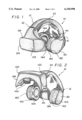
- FIG. 1 is a perspective view of the headset with the visor in the operable position
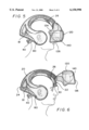
- FIG. 2 is a perspective view of the headset in the donning position
- FIG. 3 is a right side elevational view of the headset in the operable position
- FIG. 4 is a front elevational view of the headset with the visor in the operable position
- FIG. 5 is a right side elevational view showing the headset operably disposed on the head
- FIG. 6 is a right side elevational view showing the visor in the donning position
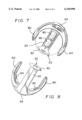
- FIG. 7 is a bottom plan view of the shell.
- FIG. 8 is a top plan view of the shell.
- the headset 10 of the present invention includes rigid shell 12 having a support beam 20 and a pair of rigid arms 60, 80 extending from the support beam, wherein a visor 120 is pivotally attached to the support beam.
- the shell 12 is of a one piece construction of a plastic such as ABS or molded polymer. It is understood the shell 12 may be manufactured as a number of individual component parts which are assembled or bonded to form a substantially rigid one piece unit.
- the support beam 20 extends from an anterior end 22 adjacent the brow over the vertex of the head to terminate at a posterior end 24 adjacent the occipital, or above the articulation of the skull and the spine. It is believed this is adjacent or at the occipital protuberance.
- the support beam 20 is a rigid piece and may include a single strut or a pair of struts which extend adjacent each side of the vertex of the head. As the support beam 20 acts as a single unit, there are no adjusting mechanisms or articulations in the beam. Referring to FIGS. 1-8, in the single strut configuration, the beam 20 has a width of approximately 2.6 inches.
- the posterior end 24 of the beam 20 terminates at the occiput above the articulation of the neck and the skull. Specifically, the posterior end 24 terminates adjacent to or above the occipital protuberance. Therefore, the head may be tilted rearwardly (or upwardly) and contact between the beam 20 and the neck or back is substantially precluded.
- the anterior end 22 includes a brow piece 30 for contacting the brow of the wearer.
- the brow is defined as the area of the head extending from the supra orbital arch to include the frontal eminence. That is, the area above the eyebrows and below the hair line.
- the brow piece 30 has a width substantially equal to the inter pupil distance.
- the brow piece 30 extends from the support beam 20 to the flare to its full width.
- the brow piece 30 defines an area having a width of approximately four inches, and a height of approximately one inch. This relatively large contact area distributes the contact force over a sufficient area to reduce pressure induced discomfort.
- the inside surface of the support beam 20 and brow piece 30, that is, the portion of the shell 12 that contacts the head, may include a foam padding 26.
- the foam padding 26 may be permanently attached to the beam 20.
- the padding 26 or portions thereof, may be releasably attached to the beam 20 by hook and loop fastener or other releasable devices.
- a rigid arm 60, 80 extends from the posterior end 24 to extend along each side of the head. That is, the arms 60, 80 and the beam 20 are an integral unit free of relative movement or adjustment.
- the arms 60, 80 extend at a slight incline to accommodate the posterior end 24 of the support beam 20 being adjacent the occipital protuberance and spaced from the neck. That is, the posterior end 24 is slightly above the ears of the wearer.
- the junction of the arms 60, 80 and the beam 20 locates a substantial portion of the mass of the headset 10 behind the ears.
- the arms 60, 80 may include a window or vent 61, 81 respectively to permit ambient air to circulate to a corresponding portion of the head, and extend to terminal ends generally aligned with the ears.
- the arms 60, 80 define an arcuate contact area around the back of the head defined by a diameter of approximately 7.5 inches.
- the terminal ends of the arms 60, 80 are sufficiently spaced apart to permit virtually any sized head to be disposed therebetween.
- the inner surface of the arms 60, 80 which house the speakers are approximately 8.6 inches apart.
- the shell 12 is sized so that each arm 60, 80 is spaced approximately 1.1 inches from the respective average ear.
- a nape strap 40 extends between the arms 60, 80 near their intersection with the posterior end 24 and is located to dispose a portion of the occiput and preferably, the occipital protuberance intermediate the posterior end of the beam 20 and the strap.
- the nape strap 40 extends between a mount on each arm 60, 80. The mount is intermediate the support beam 20 and the terminal end of the respective arm.
- the nape strap 40 may pass across the top of the neck or spine or the base of the skull.
- the nape strap 40 is flexible, movement of the head relative to the spine is not encumbered.
- the nape strap 40 is a flexible added material and its length may be adjusted by overlapping hook and loop fastener sections.
- the visor 120 is pivotally attached to the support beam 20 about a horizontal axis and is movable between the first substantially horizontal donning position and second substantially vertical operable position. Therefore, the weight of the visor 120 and visual display 140 is borne by the support beam 20, and as the support beam is rigid and seats by gravity (rather than constriction of a circumferential contact) pressure points are reduced.
- the connection point of the visor 120 to the beam 20 is above the brow piece 30, thereby reducing any torque of the headset 10 about the brow piece.
- the location of the weight bearing point between the support beam and the visor 120 is substantially vertically aligned with or even slightly rearward of the brow piece 40.
- a vertical line extending downward from the pivot intersects the brow piece 30.
- the tendency of the brow piece to be urged against the brow by the visor is reduced.
- This visor may be fixed in the operable position. Although this complicates donning the headset 10, movement of the visor 120 is not necessary. In the operable position, the visor 120 does not form a weight bearing contact with the face.
- the visor 120 includes or may be defined by a visual display 140 for presenting an image to the eyes.
- the visual display 140 may be any of a variety of displays including but not limited to LCD and projections.
- a visual display includes 3-D stereoscopic imaging with two full color LCD's with high resolutions and contrast 789 ⁇ 230 images, wherein the LCD's are 0.7 inch color liquid crystal displays having a 10.6 mm vertical picture size and a 14.3 mm horizontal size. While each eye views different images, both eyes cooperate to provide a field of depth.
- the visual display 140 may include a single image or a pair of images as shown in the figures.
- the visual display 140 may be vertically and horizontally displaced relative to each other or the visor 120.
- the visual display 140 presents substantially the entire field of view to the wearer.
- the visor 120 generally conforms to the face in the operable position. That is, the visor 120 extends from in front of the eyes to wrap a sufficient distance around the head to terminate behind the eyes.
- the visor 120 includes a front surface 122 which extends about the face to terminate behind the eyes.
- the visor 120 includes an upper deck 124 sized to be adjacent the brow, thereby seating about the brow piece 30 and subsequently precluding ambient light from above contacting the eyes, without forming a weight bearing contact with the wearer.
- the visor 120 also includes a lower deck 126 sized so that upon operable orientation of the visor, the lower deck is sufficiently spaced from the wearer to permit vision with the ambient environment. The lower deck 126 terminates adjacent the nose in the operable position of the visor 120.
- the visor 120 may house the visual display 140 for motion between the donning and the operable position, or may be substantially integrated into the visual display so that the components are inseparable. That is, the visual display 140 may be configured such that only the visual display is suspended from the brow piece 30, rather than within a visor 120. The visual display 140 then functions as the visor 120 with respect to shielding from the ambient light environment.
- Speakers 150 are located in the terminal ends of the arms 60, 80 to be adjacent the respective ears.
- the speakers 150 are high quality stereo speakers which may utilize signals from any standard stereo sound card.
- Each speakers 150 cooperates with a compensator 160.
- the compensator 160 is a resilient, deformable member which acts as a spring to urge respective contact with the head.
- the compensator 160 includes an open cell foam base 162 enclosed in a fabric or plastic cover, the speaker 150 is seated in the base 162 and a contact ring 164 attached to dispose the speaker intermediate of the contact ring and the arm.
- the contact ring 164 is also a resiliently compressible foam member which may be permanently or removably attached. Removable attachment includes releasable adhesives, hook and loop fasteners or mechanical friction fits.
- the foam base 162 and covering form a bellows which vents air during compression.
- the venting of the air through limited ports allows the compensator 160 to initially substantially resist a compressive force while yielding over the span of a few seconds.
- the compensators 160 presented to the ears of the user are formed of an open cell foam covered with cloth to form the bellows, and have a thickness of approximately 1.5 inches, with a diameter of approximately 41/4 inches. Therefore, the combined thickness of the cushioning presented to the ears is approximately 3 inches.
- the thickness of the compensator 160 allows the rigid fixed arms to accommodate a wide variety head sizes.
- the sizing of the shell 12 and compensators 160 is selected to accommodate approximately 95% of the population within the rigid, fixed shell. The head dimensions and percentile of the encompassed population is shown.
- depth is the vertical distance from the chin to the top of the head width is the horizontal distance between the ears; and length is the horizontal distance from the nasal cartilage to the back of the head.
- the total of 3 inches of compensator thickness allows the head to accommodate head sizes down a width of less than six inches.
- the compensators 160 contact an area of the head that is greater than the area of the ears. Specifically, the contact ring 164 encircles the ear, rather than pressing the ear against the head. The increased contact area again distributes the contact force over a large area.
- the compensators 160 are partially compressed upon the headset being disposed on the head, such that further compression is sufficiently resisted so as to transfer slew (torque) from the head to the headset without a significant delay. The compensators thereby assist in coupling the headset 10 to the head.
- the inside of the shell 12 may include selectively inflatable bladders 90 for sizing the headset 10 to the individual head and coupling the headset to the head.
- the compensator 160, padding 26 on the support beam 20 and brow piece 30 may include independently or commonly controlled bladders 90.
- the bladders may be filled pressurized or ambient air by the user. Alternatively, the bladders may be fluidly interconnected so that donning the headset redistributes the fluid between the bladders 90.
- the thickness and walls of the shell 12 are formed such that upon inclusion of the visual display 140, speakers 150 and associated wiring and connectors, the center of gravity of the headset 10 lies on a line extending substantially between the speakers (the ears of the user).
- the weight of the headset 10 is balanced between the anterior end 22 and the posterior end 24 of the support beam 20.
- the shell 12 and hardware are symmetrically balanced so that the left side and the right side are of substantially equal mass and the center of gravity is equally spaced between the arms 60, 80.
- the hardware is integrated into the shell 12 such that the shell alone has a center of gravity lying on a line between the terminal ends of the arms 60, 80.
- the shell 12 may be formed to accommodate different loading patterns of the hardware.
- the amount of material in the shell 12 adjacent the posterior end 24 and the junction of the arms 60, 80 to the support beam 20 creates a sufficient mass such that upon orientation of the visor 120 (and visual display 140) in the horizontal donning position, the headset 10 does not rotate about the head.
- the headset 10 includes standard input connectors for receiving visual and audio signals from a computer or other processor units.
- the headset 10 is disposed over the head so that the brow piece 40 contacts the brow and the posterior end 24 of the beam 20 is at the occiput adjacent the occipital protuberance.
- the nape strap 40 extends across the joint of the neck and the skull. Upon selective adjustment of the nape strap 40, the distance between the brow piece 40 and the nape strap is varied thereby accommodating different size heads.
- the visor 120 In the donning position, the visor 120 is tilted to be horizontal.
- the headset 10 may be placed on the head and removed from the head. The user has an unobstructed forward view.
- the weight of the headset 10 is distributed along the support beam 20.
- the visor 120 may be rotated downward to the operable position locating the visual display 140 before the eyes.
- the visor 120 and visual display 140 As the visor 120 and visual display 140 are pivoted from the support beam 20, they are suspended in the operable position which disposes the visual display before the eyes.
- the weight distribution remains along the support beam 20 and is independent of the position of the visor.
- the lower deck 126 of the visor 120 is spaced from the face by a sufficient distance so that the user can cast the eyes downward away from the visual display 140, and immediately view the external or ambient environment. That is, the visor 120 is configured to preclude substantially enclosing the users eyes. While the upper deck 124 may contact the brow, it is not a weight bearing contact.
- the compensators 160 are each compressed to provide a snug fit against the side of the head.
- the compensators 160 are oversized to enclose the ear and the surrounding portion of the head, the pressure is distributed over a larger area, rather than just the ear.
- the compensators 160 are sufficiently compressed and offer sufficient resiliency so that upon rotation of the head about any axis, or combination of axes, the slew rate of the head is transferred to the rigid shell 12.
- the compensator 160, brow piece 30 and nape strap 40 sufficiently couple the headset 10 to the head such that a slew rate of the head is sufficiently transferred to the shell 12 so that motion of the shell may be monitored to provide a signal corresponding to the motion of the head.
- the coupling between the headset 10 and head is augmented by the bladders 90 located on the inside of the shell 12.
- the contact between the headset 10 and the head through the rigid arms 60, 80 compensators 160 and posterior end 24 of the support beam 20 primarily couples the headset 10 to the head as the head may be rotated in a horizontal plane left and right.
- the support beam 20 not only couples the headset 10 to the head in forward and rearward motion, but also assists in coupling as the head turns left and right as well as side to side.
- the combination of the generally U-shaped contact between the head and (a) the support beam 20 (the closed end of the U extending along the vertex) and (b) the U-shaped contact of the arms 60, 80 and the posterior end 24 of support beam 20 (the closed end of the U being slightly inclined but generally horizontal and extending around the occiput of the head) sufficiently couples the headset 10 to the head so that monitoring motion of the headset accurately reflects in real time corresponding motion of the head. That is, the arms 60, 80 form a second substantially U-shaped engagement of the head and the support beam 20 forms a first substantially U-shaped engagement with the head, wherein the second U shaped engagement is rotated 90° about two axes from that of the beam.
- the reduced weight of the headset 10, adjustment of the nape strap 40 and the compression of the compensators 160 sufficiently couple the headset 10 to the head so that upon a slew rate imparted in the head, the headset experiences a substantially equal slew rate.
- the present headset 10 has a weight of approximately 1.2 lbs. [20 oz. (580 g).]
- the combination of the nape strap 40, brow piece 30 and compensators 160 allows the shell 12 to be a rigid one piece construction, free of any adjusting mechanism.
- the non adjustable shell 12 reduces the number of moving parts and permits a durable construction.
- the use of a rigid vertex oriented support beam 20 and the arcuate segment formed by the arms 60, 80 allows the headset 10 to operably engage the head without requiring circumferential contact or circumferential construction.
- the present headset 10 may be employed with programs which interact with the orientation of the head. Therefore, a virtual orientation system (a sourceless tracking device that monitors movement of roll, pitch and yaw) may be included in the headset in the posterior end of the beam.
- a virtual orientation system a sourceless tracking device that monitors movement of roll, pitch and yaw
Abstract
Description
______________________________________
Percentile
          Width         Length  Depth
______________________________________
Adult Male
     2.5%     5.71          6.81  8.50
  5.0% 5.77 6.87 8.20
   50% 6.10 7.20 8.70
   95% 6.43 7.63 9.20
  97.5%  6.50 7.71 9.29
Adult Female
     2.5%     5.31          6.30  6.69
  5.0% 5.38 6.38 6.81
   50% 5.71 6.81 7.28
   95% 6.10 7.14 7.72
  97.5%  6.18 7.20 7.72
Male Child
     2.5%     5.39          7.13  7.01
  5.0% 5.39 7.13 7.01
   50% 5.67 7.64 7.36
   95% 5.94 8.23 7.72
  97.5%  5.94 8.23 7.72
______________________________________
Claims (17)
Priority Applications (1)
| Application Number | Priority Date | Filing Date | Title |
|---|---|---|---|
| US08/909,221 US6150998A (en) | 1994-12-30 | 1997-08-11 | Headset for presenting video and audio signals to a wearer |
Applications Claiming Priority (2)
| Application Number | Priority Date | Filing Date | Title |
|---|---|---|---|
| US08/366,967 US5682172A (en) | 1994-12-30 | 1994-12-30 | Headset for presenting video and audio signals to a wearer |
| US08/909,221 US6150998A (en) | 1994-12-30 | 1997-08-11 | Headset for presenting video and audio signals to a wearer |
Related Parent Applications (1)
| Application Number | Title | Priority Date | Filing Date |
|---|---|---|---|
| US08/366,967 Division US5682172A (en) | 1994-12-30 | 1994-12-30 | Headset for presenting video and audio signals to a wearer |
Publications (1)
| Publication Number | Publication Date |
|---|---|
| US6150998A true US6150998A (en) | 2000-11-21 |
Family
ID=23445395
Family Applications (2)
| Application Number | Title | Priority Date | Filing Date |
|---|---|---|---|
| US08/366,967 Expired - Lifetime US5682172A (en) | 1994-12-30 | 1994-12-30 | Headset for presenting video and audio signals to a wearer |
| US08/909,221 Expired - Lifetime US6150998A (en) | 1994-12-30 | 1997-08-11 | Headset for presenting video and audio signals to a wearer |
Family Applications Before (1)
| Application Number | Title | Priority Date | Filing Date |
|---|---|---|---|
| US08/366,967 Expired - Lifetime US5682172A (en) | 1994-12-30 | 1994-12-30 | Headset for presenting video and audio signals to a wearer |
Country Status (1)
| Country | Link |
|---|---|
| US (2) | US5682172A (en) |
Cited By (22)
| Publication number | Priority date | Publication date | Assignee | Title |
|---|---|---|---|---|
| US6483483B2 (en) * | 1998-03-18 | 2002-11-19 | Sony Corporation | Eyeglasses type image display apparatus |
| US20020176330A1 (en) * | 2001-05-22 | 2002-11-28 | Gregory Ramonowski | Headset with data disk player and display |
| US6515638B2 (en) * | 1998-06-19 | 2003-02-04 | Canon Kabushiki Kaisha | Image display apparatus |
| US20050007303A1 (en) * | 2003-06-13 | 2005-01-13 | Ernest Betton | Small screen larger than life 3D TV |
| US20050078276A1 (en) * | 2003-10-10 | 2005-04-14 | Chao-Chyun Lin | Head-mounting device |
| US20060017654A1 (en) * | 2004-07-23 | 2006-01-26 | Romo Justin R | Virtual reality interactivity system and method |
| US7019715B1 (en) * | 1999-07-14 | 2006-03-28 | Minolta Co., Ltd. | Head-mounted image display apparatus |
| EP1694063A1 (en) * | 2003-11-21 | 2006-08-23 | Nishi, Kenji | Image display device and simulation apparatus |
| US20060238441A1 (en) * | 2005-04-25 | 2006-10-26 | The Boeing Company | Method and apparatus for displaying a stereoscopic image |
| US20070067885A1 (en) * | 2004-01-05 | 2007-03-29 | Fernandez Dennis S | Reconfigurable garment definition and production method |
| US20070153374A1 (en) * | 2006-01-04 | 2007-07-05 | Icuiti Corporation | Binocular Display with Improved Contrast Uniformity |
| US20080180521A1 (en) * | 2007-01-29 | 2008-07-31 | Ahearn David J | Multi-view system |
| US20090174946A1 (en) * | 2008-01-07 | 2009-07-09 | Roni Raviv | Customizable head mounted display |
| US20100309097A1 (en) * | 2009-06-04 | 2010-12-09 | Roni Raviv | Head mounted 3d display |
| US20150040295A1 (en) * | 2012-01-11 | 2015-02-12 | Pfanner Schutzbekleidung Gmbh | Safety helmet, in particular for mountain climbers and tree climbers |
| US9176325B2 (en) | 2014-02-18 | 2015-11-03 | Merge Labs, Inc. | Soft head mounted display goggles for use with mobile computing devices |
| US20160062125A1 (en) * | 2014-09-01 | 2016-03-03 | Samsung Electronics Co., Ltd. | Head-mounted display device |
| USD751072S1 (en) | 2014-02-18 | 2016-03-08 | Merge Labs, Inc. | Mobile head mounted display |
| USD755789S1 (en) | 2015-02-20 | 2016-05-10 | Merge Labs, Inc. | Mobile head mounted display |
| USD760701S1 (en) | 2015-02-20 | 2016-07-05 | Merge Labs, Inc. | Mobile head mounted display controller |
| US20170255229A1 (en) * | 2016-03-04 | 2017-09-07 | DODOcase, Inc. | Virtual reality viewer |
| US20190220057A1 (en) * | 2016-09-27 | 2019-07-18 | SZ DJI Technology Co., Ltd. | Video glasses |
Families Citing this family (39)
| Publication number | Priority date | Publication date | Assignee | Title |
|---|---|---|---|---|
| US5682172A (en) * | 1994-12-30 | 1997-10-28 | Forte Technologies, Inc. | Headset for presenting video and audio signals to a wearer |
| JPH09307951A (en) * | 1996-03-15 | 1997-11-28 | Matsushita Electric Ind Co Ltd | Spread spectrum communication equipment |
| US6765895B1 (en) | 1996-03-15 | 2004-07-20 | Matsushita Electric Industrial Co., Ltd. | Spectrum spread communication system |
| US6292305B1 (en) * | 1997-08-25 | 2001-09-18 | Ricoh Company, Ltd. | Virtual screen display device |
| US6038330A (en) * | 1998-02-20 | 2000-03-14 | Meucci, Jr.; Robert James | Virtual sound headset and method for simulating spatial sound |
| JP3256183B2 (en) * | 1998-08-17 | 2002-02-12 | 株式会社エム・アール・システム研究所 | Mounting mechanism and head-mounted device |
| US7124425B1 (en) * | 1999-03-08 | 2006-10-17 | Immersion Entertainment, L.L.C. | Audio/video system and method utilizing a head mounted apparatus with noise attenuation |
| US6578203B1 (en) | 1999-03-08 | 2003-06-10 | Tazwell L. Anderson, Jr. | Audio/video signal distribution system for head mounted displays |
| US7210160B2 (en) | 1999-05-28 | 2007-04-24 | Immersion Entertainment, L.L.C. | Audio/video programming and charging system and method |
| US20020057364A1 (en) | 1999-05-28 | 2002-05-16 | Anderson Tazwell L. | Electronic handheld audio/video receiver and listening/viewing device |
| US6384764B1 (en) | 2000-01-14 | 2002-05-07 | Todd Cumberland | Inflatable radar reflector |
| WO2002077670A2 (en) * | 2001-03-16 | 2002-10-03 | David Wilder | Night-sight device |
| WO2004034617A1 (en) | 2002-10-07 | 2004-04-22 | Immersion Entertainment, Llc | System and method for providing event spectators with audio/video signals pertaining to remote events |
| EP1623266B1 (en) * | 2003-05-12 | 2009-10-28 | Elbit Systems Ltd. | Method and system for audiovisual communication |
| US7593687B2 (en) | 2003-10-07 | 2009-09-22 | Immersion Entertainment, Llc | System and method for providing event spectators with audio/video signals pertaining to remote events |
| US11228753B1 (en) | 2006-12-28 | 2022-01-18 | Robert Edwin Douglas | Method and apparatus for performing stereoscopic zooming on a head display unit |
| US11315307B1 (en) | 2006-12-28 | 2022-04-26 | Tipping Point Medical Images, Llc | Method and apparatus for performing rotating viewpoints using a head display unit |
| US11275242B1 (en) | 2006-12-28 | 2022-03-15 | Tipping Point Medical Images, Llc | Method and apparatus for performing stereoscopic rotation of a volume on a head display unit |
| US10795457B2 (en) | 2006-12-28 | 2020-10-06 | D3D Technologies, Inc. | Interactive 3D cursor |
| US8384771B1 (en) * | 2006-12-28 | 2013-02-26 | David Byron Douglas | Method and apparatus for three dimensional viewing of images |
| JP5039430B2 (en) * | 2007-05-21 | 2012-10-03 | 川崎重工業株式会社 | Helmet holder and information disclosure apparatus |
| WO2015068587A1 (en) * | 2013-11-05 | 2015-05-14 | ソニー株式会社 | Information processing device, method of processing information, and program |
| CN106455735B (en) * | 2014-05-05 | 2021-01-08 | 能源激光器有限公司 | Helmet with video acquisition device and display |
| US9955049B2 (en) * | 2014-07-31 | 2018-04-24 | Bell Sports, Inc. | Helmet with integrated electronics and helmet visor controls |
| USD752680S1 (en) * | 2014-08-25 | 2016-03-29 | Samsung Electronics Co., Ltd. | Cover for head-mounted display device |
| USD741327S1 (en) * | 2015-04-16 | 2015-10-20 | Vladimir Reznik | Head mounted display |
| US20180160759A1 (en) * | 2015-05-18 | 2018-06-14 | Cyclevision Pty Ltd | Bicycle Helmet |
| CN104867175A (en) * | 2015-06-02 | 2015-08-26 | 孟君乐 | Real-scene displaying device for virtual effect picture and implementing method therefor |
| WO2017173943A1 (en) * | 2016-04-06 | 2017-10-12 | 成都虚拟世界科技有限公司 | Head-mounted structure and head-mounted device |
| CN105725344A (en) * | 2016-04-28 | 2016-07-06 | 江苏卡罗卡国际动漫城有限公司 | Conveniently adjustable AR (augmented reality) helmet |
| US10488830B2 (en) | 2016-08-10 | 2019-11-26 | Intel Corporation | Automatic adjustment of head mounted display straps |
| US10071307B1 (en) | 2017-03-09 | 2018-09-11 | Tzumi Electronics LLC | Virtual reality headset with retractable earphones |
| CN110446436A (en) | 2017-03-23 | 2019-11-12 | 惠普发展公司,有限责任合伙企业 | It is adjusted by the band of sensor |
| US10901224B2 (en) * | 2017-04-28 | 2021-01-26 | Intel Corporation | Neck mounted computing device with display connectivity |
| CN208607439U (en) * | 2018-07-31 | 2019-03-15 | 青岛小鸟看看科技有限公司 | A kind of top strap and a kind of helmet |
| TWM624252U (en) * | 2020-07-29 | 2022-03-01 | 政 李 | Wearable reality device |
| US20220035401A1 (en) * | 2020-07-29 | 2022-02-03 | James Cheng Lee | Wearable reality device |
| US20230110539A1 (en) * | 2021-10-13 | 2023-04-13 | Meta Platforms, Inc. | Methods and apparatus for fabricating curved elastic bands and articles incorporating curved elastic bands |
| CN116203733A (en) * | 2023-04-28 | 2023-06-02 | 中国兵器装备集团自动化研究所有限公司 | Mixed reality wearing equipment |
Citations (11)
| Publication number | Priority date | Publication date | Assignee | Title |
|---|---|---|---|---|
| US4395731A (en) * | 1981-10-16 | 1983-07-26 | Arnold Schoolman | Television microscope surgical method and apparatus therefor |
| US4703879A (en) * | 1985-12-12 | 1987-11-03 | Varo, Inc. | Night vision goggle headgear |
| US4737972A (en) * | 1982-02-24 | 1988-04-12 | Arnold Schoolman | Stereoscopic fluoroscope arrangement |
| US4817633A (en) * | 1987-11-05 | 1989-04-04 | The United States Of America As Represented By The United States National Aeronautics And Space Administration | Lightweight device to stimulate and monitor human vestibulo-ocular reflex |
| US4952024A (en) * | 1986-08-29 | 1990-08-28 | Gale Thomas S | Three-dimensional sight and sound reproduction apparatus for individual use |
| US5347400A (en) * | 1993-05-06 | 1994-09-13 | Ken Hunter | Optical system for virtual reality helmet |
| JPH06315124A (en) * | 1993-04-28 | 1994-11-08 | Sony Corp | Spectacles type video display device |
| USD369595S (en) | 1994-10-19 | 1996-05-07 | Forte Technologies, Inc. | Virtual reality headset |
| US5682172A (en) * | 1994-12-30 | 1997-10-28 | Forte Technologies, Inc. | Headset for presenting video and audio signals to a wearer |
| US5683297A (en) * | 1994-12-16 | 1997-11-04 | Raviv; Roni | Head mounted modular electronic game system |
| US5696521A (en) * | 1994-06-22 | 1997-12-09 | Astounding Technologies (M) Sdn. Bhd. | Video headset |
Family Cites Families (14)
| Publication number | Priority date | Publication date | Assignee | Title |
|---|---|---|---|---|
| US2966550A (en) * | 1956-11-08 | 1960-12-27 | Jack H Golberg | Hair dryer sound system |
| US2955156A (en) * | 1957-05-24 | 1960-10-04 | Morton L Heilig | Stereoscopic-television apparatus for individual use |
| US3050870A (en) * | 1961-01-10 | 1962-08-28 | Morton L Heilig | Sensorama simulator |
| US3261028A (en) * | 1962-08-14 | 1966-07-19 | James N Coletta | Noise attenuating device |
| US3614314A (en) * | 1967-03-21 | 1971-10-19 | Bendix Corp | Optical display means for an all-weather landing system of an aircraft |
| DE2410146C2 (en) * | 1974-03-02 | 1976-01-02 | Sennheiser Electronic Kg, 3002 Wennebostel | Method and device for stereotonic recording of sound events |
| US3923370A (en) * | 1974-10-15 | 1975-12-02 | Honeywell Inc | Head mounted displays |
| US4208098A (en) * | 1978-01-09 | 1980-06-17 | Frank Johnson | Odor dispensing system for hand-held stereoscopic viewer and replaceable container therefor |
| US4310849A (en) * | 1979-06-11 | 1982-01-12 | Glass Stuart M | Stereoscopic video system |
| US4342560A (en) * | 1980-05-16 | 1982-08-03 | Borg-Warner Corporation | Composite chain link assembly |
| GB2113058B (en) * | 1981-12-18 | 1985-10-02 | Andrew Chapman | Improvements in or relating to apparatus and methods for producing visual displays |
| US4574197A (en) * | 1983-03-24 | 1986-03-04 | Hughes Aircraft Company | Dual field of view sensor |
| US4666638A (en) * | 1985-08-27 | 1987-05-19 | Remington Products, Inc. | Fragrance device |
| US5373857A (en) * | 1993-06-18 | 1994-12-20 | Forte Technologies, Inc. | Head tracking apparatus |
-
1994
- 1994-12-30 US US08/366,967 patent/US5682172A/en not_active Expired - Lifetime
-
1997
- 1997-08-11 US US08/909,221 patent/US6150998A/en not_active Expired - Lifetime
Patent Citations (11)
| Publication number | Priority date | Publication date | Assignee | Title |
|---|---|---|---|---|
| US4395731A (en) * | 1981-10-16 | 1983-07-26 | Arnold Schoolman | Television microscope surgical method and apparatus therefor |
| US4737972A (en) * | 1982-02-24 | 1988-04-12 | Arnold Schoolman | Stereoscopic fluoroscope arrangement |
| US4703879A (en) * | 1985-12-12 | 1987-11-03 | Varo, Inc. | Night vision goggle headgear |
| US4952024A (en) * | 1986-08-29 | 1990-08-28 | Gale Thomas S | Three-dimensional sight and sound reproduction apparatus for individual use |
| US4817633A (en) * | 1987-11-05 | 1989-04-04 | The United States Of America As Represented By The United States National Aeronautics And Space Administration | Lightweight device to stimulate and monitor human vestibulo-ocular reflex |
| JPH06315124A (en) * | 1993-04-28 | 1994-11-08 | Sony Corp | Spectacles type video display device |
| US5347400A (en) * | 1993-05-06 | 1994-09-13 | Ken Hunter | Optical system for virtual reality helmet |
| US5696521A (en) * | 1994-06-22 | 1997-12-09 | Astounding Technologies (M) Sdn. Bhd. | Video headset |
| USD369595S (en) | 1994-10-19 | 1996-05-07 | Forte Technologies, Inc. | Virtual reality headset |
| US5683297A (en) * | 1994-12-16 | 1997-11-04 | Raviv; Roni | Head mounted modular electronic game system |
| US5682172A (en) * | 1994-12-30 | 1997-10-28 | Forte Technologies, Inc. | Headset for presenting video and audio signals to a wearer |
Cited By (43)
| Publication number | Priority date | Publication date | Assignee | Title |
|---|---|---|---|---|
| US6483483B2 (en) * | 1998-03-18 | 2002-11-19 | Sony Corporation | Eyeglasses type image display apparatus |
| US6515638B2 (en) * | 1998-06-19 | 2003-02-04 | Canon Kabushiki Kaisha | Image display apparatus |
| US7019715B1 (en) * | 1999-07-14 | 2006-03-28 | Minolta Co., Ltd. | Head-mounted image display apparatus |
| US20020176330A1 (en) * | 2001-05-22 | 2002-11-28 | Gregory Ramonowski | Headset with data disk player and display |
| US20050007303A1 (en) * | 2003-06-13 | 2005-01-13 | Ernest Betton | Small screen larger than life 3D TV |
| US20050078276A1 (en) * | 2003-10-10 | 2005-04-14 | Chao-Chyun Lin | Head-mounting device |
| EP1694063A4 (en) * | 2003-11-21 | 2008-01-30 | Kenji Nishi | Image display device and simulation apparatus |
| EP1694063A1 (en) * | 2003-11-21 | 2006-08-23 | Nishi, Kenji | Image display device and simulation apparatus |
| US8930012B2 (en) | 2004-01-05 | 2015-01-06 | Dennis S. Fernandez | Reconfigurable garment definition and production method |
| US20070067885A1 (en) * | 2004-01-05 | 2007-03-29 | Fernandez Dennis S | Reconfigurable garment definition and production method |
| US9858361B2 (en) | 2004-01-05 | 2018-01-02 | Dennis S. Fernandez | Reconfigurable garment definition and production method |
| US20080221403A1 (en) * | 2004-01-05 | 2008-09-11 | Fernandez Dennis S | Reconfigurable Garment Definition and Production Method |
| US20090018691A1 (en) * | 2004-01-05 | 2009-01-15 | Fernandez Dennis S | Reconfigurable Garment Definition and Production Method |
| US8065029B2 (en) | 2004-01-05 | 2011-11-22 | Dennis Sunga Fernandez | Reconfigurable garment definition and production method |
| US8185231B2 (en) | 2004-01-05 | 2012-05-22 | Dennis Sunga Fernandez | Reconfigurable garment definition and production method |
| US7593783B2 (en) * | 2004-01-05 | 2009-09-22 | Fernandez Dennis S | Reconfigurable garment definition and production method |
| US20090319076A1 (en) * | 2004-01-05 | 2009-12-24 | Fernandez Dennis S | Reconfigurable Garment Definition and Production Method |
| US8116895B2 (en) | 2004-01-05 | 2012-02-14 | Dennis Sunga Fernandez | Reconfigurable garment definition and production method |
| US7930056B2 (en) | 2004-01-05 | 2011-04-19 | Dennis Fernandez | Reconfigurable garment definition and production method |
| US20060017654A1 (en) * | 2004-07-23 | 2006-01-26 | Romo Justin R | Virtual reality interactivity system and method |
| US20060238441A1 (en) * | 2005-04-25 | 2006-10-26 | The Boeing Company | Method and apparatus for displaying a stereoscopic image |
| US20070153374A1 (en) * | 2006-01-04 | 2007-07-05 | Icuiti Corporation | Binocular Display with Improved Contrast Uniformity |
| US7515344B2 (en) | 2006-01-04 | 2009-04-07 | Vuzlx Corporation | Binocular display with improved contrast uniformity |
| US9300949B2 (en) * | 2007-01-29 | 2016-03-29 | David J. Ahearn | Multi-view system |
| US20080180521A1 (en) * | 2007-01-29 | 2008-07-31 | Ahearn David J | Multi-view system |
| US20090174946A1 (en) * | 2008-01-07 | 2009-07-09 | Roni Raviv | Customizable head mounted display |
| US20100309097A1 (en) * | 2009-06-04 | 2010-12-09 | Roni Raviv | Head mounted 3d display |
| US20150040295A1 (en) * | 2012-01-11 | 2015-02-12 | Pfanner Schutzbekleidung Gmbh | Safety helmet, in particular for mountain climbers and tree climbers |
| US9113671B2 (en) * | 2012-01-11 | 2015-08-25 | Pfanner Schutzbekleidung Gmbh | Safety helmet, in particular for mountain climbers and tree climbers |
| US9274340B2 (en) | 2014-02-18 | 2016-03-01 | Merge Labs, Inc. | Soft head mounted display goggles for use with mobile computing devices |
| US10302951B2 (en) | 2014-02-18 | 2019-05-28 | Merge Labs, Inc. | Mounted display goggles for use with mobile computing devices |
| USD751072S1 (en) | 2014-02-18 | 2016-03-08 | Merge Labs, Inc. | Mobile head mounted display |
| US9176325B2 (en) | 2014-02-18 | 2015-11-03 | Merge Labs, Inc. | Soft head mounted display goggles for use with mobile computing devices |
| US9377626B2 (en) | 2014-02-18 | 2016-06-28 | Merge Labs, Inc. | Remote control augmented motion data capture |
| US9696553B2 (en) | 2014-02-18 | 2017-07-04 | Merge Labs, Inc. | Soft head mounted display goggles for use with mobile computing devices |
| US9599824B2 (en) | 2014-02-18 | 2017-03-21 | Merge Labs, Inc. | Soft head mounted display goggles for use with mobile computing devices |
| US9733480B2 (en) * | 2014-09-01 | 2017-08-15 | Samsung Electronics Co., Ltd. | Head-mounted display device |
| US20160062125A1 (en) * | 2014-09-01 | 2016-03-03 | Samsung Electronics Co., Ltd. | Head-mounted display device |
| USD760701S1 (en) | 2015-02-20 | 2016-07-05 | Merge Labs, Inc. | Mobile head mounted display controller |
| USD755789S1 (en) | 2015-02-20 | 2016-05-10 | Merge Labs, Inc. | Mobile head mounted display |
| US20170255229A1 (en) * | 2016-03-04 | 2017-09-07 | DODOcase, Inc. | Virtual reality viewer |
| US20190220057A1 (en) * | 2016-09-27 | 2019-07-18 | SZ DJI Technology Co., Ltd. | Video glasses |
| US10871799B2 (en) * | 2016-09-27 | 2020-12-22 | SZ DJI Technology Co., Ltd. | Video glasses |
Also Published As
| Publication number | Publication date |
|---|---|
| US5682172A (en) | 1997-10-28 |
Similar Documents
| Publication | Publication Date | Title |
|---|---|---|
| US6150998A (en) | Headset for presenting video and audio signals to a wearer | |
| US6034653A (en) | Head-set display device | |
| US5003300A (en) | Head mounted display for miniature video display system | |
| US5457751A (en) | Ergonomic headset | |
| CN209879142U (en) | Head-mounted view device for virtual reality or augmented reality | |
| CN206193358U (en) | Bandeau system of portable virtual reality glasses | |
| US4259747A (en) | Protective communications helmet | |
| JP6953506B2 (en) | Flexible mounting arm | |
| CN209728332U (en) | A kind of VR helmet that stability is good | |
| US20240103282A1 (en) | A head mounted display system with positioning, stabilising and interfacing structures | |
| US5533137A (en) | Earphones | |
| US6912727B2 (en) | Head harness for night vision device | |
| US20090158501A1 (en) | Display device support system | |
| JPH10197825A (en) | Head mount type display | |
| US5388276A (en) | Headwear | |
| US11874473B2 (en) | Positioning and stabilising structure and system incorporating same | |
| WO2000055673A1 (en) | Headset boom for image display module | |
| CN215575934U (en) | Novel interactive equipment is felt to body | |
| CN108845421A (en) | A kind of VR glasses of included earphone-type | |
| GB2209923A (en) | A combined ear and eye protector unit | |
| WO2000055672A9 (en) | Headset for headmounted display | |
| CN216670407U (en) | Wear comfortable new-type AR/VR helmet | |
| CN219179707U (en) | Shoulder support type AR head display device | |
| CN218446244U (en) | Prevent 3D glasses of pressure | |
| JPH0836155A (en) | Head-mounted video display device |
Legal Events
| Date | Code | Title | Description |
|---|---|---|---|
| STCF | Information on status: patent grant |
Free format text: PATENTED CASE |
|
| AS | Assignment |
Owner name: KAOTECH CORPORATION, MASSACHUSETTS Free format text: ASSIGNMENT OF ASSIGNORS INTEREST;ASSIGNOR:FORTE TECHNOLOGIES, INC.;REEL/FRAME:012463/0357 Effective date: 19971024 Owner name: INTERACTIVE IMAGING SYSTEMS, INC., NEW YORK Free format text: CHANGE OF NAME;ASSIGNOR:KAOTECH CORPORATION;REEL/FRAME:012463/0477 Effective date: 19980312 |
|
| FPAY | Fee payment |
Year of fee payment: 4 |
|
| AS | Assignment |
Owner name: ICUITI CORPORATION, NEW YORK Free format text: CHANGE OF NAME;ASSIGNOR:VICUITY CORPORATION;REEL/FRAME:016290/0922 Effective date: 20041216 Owner name: VICUITY CORPORATION, NEW YORK Free format text: CHANGE OF NAME;ASSIGNOR:INTERACTIVE IMAGING SYSTEMS, INC.;REEL/FRAME:016290/0919 Effective date: 20040817 |
|
| AS | Assignment |
Owner name: VUZIX CORPORATION, NEW YORK Free format text: CHANGE OF NAME;ASSIGNOR:ICUITI CORPORATION;REEL/FRAME:019991/0932 Effective date: 20070912 |
|
| FPAY | Fee payment |
Year of fee payment: 8 |
|
| AS | Assignment |
Owner name: LC CAPITAL MASTER FUND LTD, NEW YORK Free format text: SECURITY AGREEMENT;ASSIGNOR:VUZIX CORPORATION;REEL/FRAME:025573/0632 Effective date: 20101223 |
|
| FPAY | Fee payment |
Year of fee payment: 12 |
|
| AS | Assignment |
Owner name: FORTE TECHNOLOGIES, INC., NEW YORK Free format text: ASSIGNMENT OF ASSIGNORS INTEREST;ASSIGNORS:TRAVERS, PAUL J.;TAYLOR, ROBERT E.;REEL/FRAME:029542/0167 Effective date: 19941230 |