US6147871A - Low profile computer assembly using paired back-to-back peripheral card connectors that support different bus form factors and are mounted on a riser card - Google Patents
Low profile computer assembly using paired back-to-back peripheral card connectors that support different bus form factors and are mounted on a riser card Download PDFInfo
- Publication number
- US6147871A US6147871A US09/195,881 US19588198A US6147871A US 6147871 A US6147871 A US 6147871A US 19588198 A US19588198 A US 19588198A US 6147871 A US6147871 A US 6147871A
- Authority
- US
- United States
- Prior art keywords
- card
- peripheral
- riser
- bus
- riser card
- Prior art date
- Legal status (The legal status is an assumption and is not a legal conclusion. Google has not performed a legal analysis and makes no representation as to the accuracy of the status listed.)
- Expired - Fee Related
Links
Images
Classifications
-
- G—PHYSICS
- G06—COMPUTING; CALCULATING OR COUNTING
- G06F—ELECTRIC DIGITAL DATA PROCESSING
- G06F13/00—Interconnection of, or transfer of information or other signals between, memories, input/output devices or central processing units
- G06F13/38—Information transfer, e.g. on bus
- G06F13/40—Bus structure
- G06F13/4063—Device-to-bus coupling
- G06F13/409—Mechanical coupling
-
- H—ELECTRICITY
- H05—ELECTRIC TECHNIQUES NOT OTHERWISE PROVIDED FOR
- H05K—PRINTED CIRCUITS; CASINGS OR CONSTRUCTIONAL DETAILS OF ELECTRIC APPARATUS; MANUFACTURE OF ASSEMBLAGES OF ELECTRICAL COMPONENTS
- H05K1/00—Printed circuits
- H05K1/02—Details
- H05K1/14—Structural association of two or more printed circuits
-
- H—ELECTRICITY
- H05—ELECTRIC TECHNIQUES NOT OTHERWISE PROVIDED FOR
- H05K—PRINTED CIRCUITS; CASINGS OR CONSTRUCTIONAL DETAILS OF ELECTRIC APPARATUS; MANUFACTURE OF ASSEMBLAGES OF ELECTRICAL COMPONENTS
- H05K7/00—Constructional details common to different types of electric apparatus
- H05K7/14—Mounting supporting structure in casing or on frame or rack
- H05K7/1438—Back panels or connecting means therefor; Terminals; Coding means to avoid wrong insertion
- H05K7/1439—Back panel mother boards
- H05K7/1445—Back panel mother boards with double-sided connections
-
- H—ELECTRICITY
- H05—ELECTRIC TECHNIQUES NOT OTHERWISE PROVIDED FOR
- H05K—PRINTED CIRCUITS; CASINGS OR CONSTRUCTIONAL DETAILS OF ELECTRIC APPARATUS; MANUFACTURE OF ASSEMBLAGES OF ELECTRICAL COMPONENTS
- H05K7/00—Constructional details common to different types of electric apparatus
- H05K7/14—Mounting supporting structure in casing or on frame or rack
- H05K7/1438—Back panels or connecting means therefor; Terminals; Coding means to avoid wrong insertion
- H05K7/1459—Circuit configuration, e.g. routing signals
-
- H—ELECTRICITY
- H05—ELECTRIC TECHNIQUES NOT OTHERWISE PROVIDED FOR
- H05K—PRINTED CIRCUITS; CASINGS OR CONSTRUCTIONAL DETAILS OF ELECTRIC APPARATUS; MANUFACTURE OF ASSEMBLAGES OF ELECTRICAL COMPONENTS
- H05K1/00—Printed circuits
- H05K1/02—Details
- H05K1/14—Structural association of two or more printed circuits
- H05K1/141—One or more single auxiliary printed circuits mounted on a main printed circuit, e.g. modules, adapters
-
- H—ELECTRICITY
- H05—ELECTRIC TECHNIQUES NOT OTHERWISE PROVIDED FOR
- H05K—PRINTED CIRCUITS; CASINGS OR CONSTRUCTIONAL DETAILS OF ELECTRIC APPARATUS; MANUFACTURE OF ASSEMBLAGES OF ELECTRICAL COMPONENTS
- H05K2201/00—Indexing scheme relating to printed circuits covered by H05K1/00
- H05K2201/04—Assemblies of printed circuits
- H05K2201/045—Hierarchy auxiliary PCB, i.e. more than two levels of hierarchy for daughter PCBs are important
-
- H—ELECTRICITY
- H05—ELECTRIC TECHNIQUES NOT OTHERWISE PROVIDED FOR
- H05K—PRINTED CIRCUITS; CASINGS OR CONSTRUCTIONAL DETAILS OF ELECTRIC APPARATUS; MANUFACTURE OF ASSEMBLAGES OF ELECTRICAL COMPONENTS
- H05K2201/00—Indexing scheme relating to printed circuits covered by H05K1/00
- H05K2201/10—Details of components or other objects attached to or integrated in a printed circuit board
- H05K2201/10007—Types of components
- H05K2201/10189—Non-printed connector
-
- H—ELECTRICITY
- H05—ELECTRIC TECHNIQUES NOT OTHERWISE PROVIDED FOR
- H05K—PRINTED CIRCUITS; CASINGS OR CONSTRUCTIONAL DETAILS OF ELECTRIC APPARATUS; MANUFACTURE OF ASSEMBLAGES OF ELECTRICAL COMPONENTS
- H05K3/00—Apparatus or processes for manufacturing printed circuits
- H05K3/36—Assembling printed circuits with other printed circuits
- H05K3/366—Assembling printed circuits with other printed circuits substantially perpendicularly to each other
Definitions
- This invention generally relates to the field of computer system assemblies and more particularly to the assembly of circuit boards contained therein.
- riser card assemblies for attaching peripheral cards to a computer system.
- Some such assemblies are designed such that peripheral cards attach to respective connectors on one side or on both sides of the riser card.
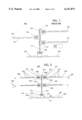
- a prior art riser card assembly 100 uses both sides of the riser card for placing staggered peripheral card connectors on the sides of a riser card.
- the assembly 100 includes a main circuit board 102 upon which a universal connector 105 is placed.
- a conventional riser card 110 with electrically conductive metallic circuit traces having a mating connector is attached to the connector 105 which holds the riser card 110 in an upright position.
- the riser card 110 has opposing sides 111 and 112 where each side includes one or more staggered peripheral card connectors 150 for receiving a corresponding number of peripheral cards 130.
- Each peripheral card 130 has a component side 131 where the electronic circuitry in the form of integrated circuit chips and discrete components are placed thereon.
- the component side 131 of the peripheral cards 130 plugged into first side 111 of riser card 110 face a downwardly direction, where as, the peripheral cards 130 with components side 131 plugged into second side 112 face an upwardly direction.
- the conventional staggered connector arrangement utilizes connectors having rows of pins 151 which attach to the riser card via corresponding conductive through-holes formed on the opposing surfaces of the riser card 110.
- a low profile computer assembly which is capable of receiving one or more peripheral cards.
- the computer assembly includes a circuit board having a card connector placed thereon for receiving a riser card and holding it in an upright position in relation to the main circuit board.
- Two peripheral card connectors are paired together and are attached to the riser card.
- the two paired peripheral card connectors extend outwardly from opposing sides of the riser card.
- the connectors extend outwardly along a single axis which is substantially perpendicular to the riser card and in parallel to the surface of the circuit board.
- the assembly includes means for electrically coupling and mechanically securing the paired peripheral cards to the riser card in a parallel orientation with the card connector.
- riser card of the present inventory may have a universal footprint formed on its opposing sides for accommodating various bus form factors.
- FIG. 1 is a side view of a prior art riser card having staggered peripheral card connectors
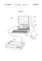
- FIG. 2 is a view of an exemplary personal computer system incorporating the low profile computer assembly of the present invention
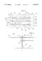
- FIG. 3 is side view of a riser card assembly according to the present invention.
- FIG. 4 is cross sectional along line A--A of FIG. 3;
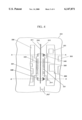
- FIG. 5 is front view of the riser card of FIG. 3 showing peripheral card connectors for various buses;
- FIG. 6 is side view of another embodiment of the computer assembly according to the present invention with a bus bridge chip
- a personal computer system 200 is shown to include a processor unit 202, a display 204, a keyboard 210, a mouse 212, a printer 214, a diskette drive 206.
- a personal computer assembly circuit board is included within the processor unit 202 to be a desktop model where the processor unit's longest side is in a horizontal orientation with respect to its supporting surface.
- the present invention is equally applicable to a stand-up model where the processor unit's longest side is perpendicular to the supporting surface. Referring to FIG.
- the assembly 300 includes a circuit board 302 having electrical components 303 comprising IC chips and passive and active components, being electrically connected to each other according to a specific personal computer design architecture, such as well known uni- or multi-processing system architectures. Additional and complementary functions and features are provided by attaching peripheral cards 330 to the computer system 200.
- peripheral cards 330 may for example comprise hard disk controllers for enhancing storage capacity of the computer system or communication devices for connecting the computer system of the present invention to a local or a wide area network.
- the peripheral cards 330 communicate with the computer system over one or more I/O buses, where such buses comply with specified Input/Output protocols.
- Each bus standard also specifies a physical form factor which defines among other things, a corresponding size, shape and contact spacing.
- I/O protocols and form factors may be specified by standard specifications such as those relating to ISA, PCL SCSL or Micro Channel.
- the specification for each bus form factor allows peripheral card manufacturers to produce cards which could attach to corresponding peripheral card connectors of the computer system.
- the main circuit board 302 includes a riser card connector 305 which is placed on one of its opposing surfaces.
- a riser card 310 having opposing sides 311 and 312 is inserted into the card connector 305 and is held in a substantially upright position with respect to the main circuit board 302.
- the riser card 310 includes a plurality of peripheral card connectors 350 disposed on its opposing sides 311 and 312.
- a plurality of peripheral cards 330 are attached to the assembly 300 via the peripheral card connectors 350 which extend from opposing sides of the riser card 310.
- the riser card 310 includes a set of electrical contacts 314 formed at its connecting end for coupling to corresponding electrical contacts 316 on the card connector 305.
- the riser card 310 may be fabricated from an epoxy glass composite or any other suitable material with electrically conductive metallic circuit traces (Shown in FIG. 5 by reference numeral 564)
- the circuit traces are disposed on the riser card for electrically connecting the circuitry of the peripheral cards 330 to the circuitry disposed on the circuit board 302 via the peripheral card connector 350 and the riser card connector 305.
- the riser card connector 305 may be formed using thermoplastic polyester or other suitable material and attached to the main circuit board 302 via suitable electrical contacts (not shown). As such, the peripheral cards 330 are electrically connected to the circuit board 302 via, peripheral card connectors 350, the riser card 310 and the card connector 305.
- a low profile computer assembly is provided by situating two peripheral card connectors 350, having exemplary height(s) 385 (shown in FIG. 3), width(s) 390 and depth(s) 395 (both shown in FIG. 4) in a back to back non-staggered position with respect to each other.
- Each connector 350 extends outwardly from a corresponding opposing side 311 or 312 of the riser card 310 along a single axis A--A which runs perpendicular to the riser card.
- the back to back uniaxial peripheral card connectors 350 are situated in symmetry with respect to the riser card 310.
- the assembly 300 may include more than one set of paired connectors, such as the back to back uniaxial pair of peripheral card connectors 355, which are similarly situated in a back-to-back uniaxial orientation and extend outwardly from the opposing sides 311 and 312 along another axis B--B which also runs perpendicular to the riser card 310.
- Each card connector 350 also includes symmetrically opposing contacts 320 for providing electrical connection to corresponding contacts 321 of the peripheral cards 330.
- the back to back uniaxial connectors 350 are fastened to the riser card 310 by appropriate retention means, such as screws and nuts, bonding adhesive, etc, to retain the peripheral card connectors 350 in a substantially parallel orientation with respect to the card connector 305: parallel in the sense that a longitudinal axis of a peripheral card connector, 350, is parallel to a similar longitudinal axis of the riser card connector, 305. It may be appreciated that the advantages offered by the assembly of the present invention are derived from back-to-back uniaxial position of the two peripheral cards connectors 350 and the parallel orientation of such connectors with respect to the riser card connector 305.
- the back-to-back arrangement of the connectors 350 eliminates the additional height introduced by prior art's staggered arrangement.
- the parallel orientation of the back-to-back connectors 350 with respect to the card connector 305 makes the height of the riser card independent of relatively long width 390 of the connectors 350 and thus, dependent upon substantially short height 385 of such connectors.
- the connectors 350 are attached to the riser card 310 via an screw/nut arrangement 340.
- the connector contacts 320 of the connector 350 are electrically coupled to corresponding peripheral card contacts 321.
- the peripheral card contacts 321 are electrically coupled to corresponding electrical contacts 314 via circuit traces 564 (shown in FIG. 5) disposed on one or both sides 311 and 312 of the riser card utilizing well known circuit board manufacturing techniques.
- FIG. 4 is a cross-sectional view, along axis A--A of FIG. 3 of two peripheral card connectors 350 as they attach to the riser card 310 in a back to back uniaxial manner according to the present invention.
- the peripheral card connectors 350 extend outwardly from the opposing sides 311 and 312 of the riser card 310 along axis A--A and connect to the peripheral cards 330 to the riser card from one side and to the riser card 310 from the other side.
- the peripheral card connector 350 attached to the riser card circuitry via suitable contacts (not shown). This arrangement positions the peripheral cards 330 in symmetrical situation with respect to the riser card 310.
- peripheral card connector contacts 320, and corresponding peripheral card contacts 321 which produce the electrical connection between the computer system 200 and the peripheral cards 330.
- the peripheral card connectors 350 may be provided in a variety of arrangements.
- the peripheral card connectors 350 may be integrated into a single solid piece, such as a molded piece, allowing them to extend outwardly from the opposing sides of the riser card 310 in accordance with the present invention Obviously, in this integrated arrangement, suitable openings must be formed on the riser card 310 to allow the peripheral card connectors 350 to be positioned in substantial symmetry with respect to the riser card 310.
- the electrical contacts 320 may be formed at the opposing ends of the connector 350 utilizing well known molding, electroplating or other suitable connector placement techniques. The electrical contacts 320 of the connector 350 are positioned and spaced in accordance with corresponding bus form factor.
- the connector 350 and its electrical contacts 320 may be disposed at opposing surfaces in accordance with their corresponding form factor definition.
- the peripheral card connectors 350 may be positioned against each other in a back to back uniaxial arrangement.
- the opposing contacts 320 extend outwardly along the axis A--A while the peripheral card when attaches is positioned perpendicular to the riser card 310 and in parallel to the circuit board 302.
- FIG. 4 also shows a mechanical fastening arrangement for attaching the connector 350 to the riser card utilizing threaded screws, with corresponding nuts for holding the connectors 350 in parallel orientation with respect to the riser card connector 305.
- suitable fastening means such as rivets, bonding adhesives, etc., may be used in lieu of the depicted arrangement.
- the computer system 200 of the present invention be capable of supporting one or more peripheral cards with the same or differing I/O bus form factors in any combination.
- each of the back to back peripheral card connectors 350 may be conforming to identical or non-identical form factors.
- the bus form factor on one side of the riser card 310 may conform to ISA standard while the form factor of the other side may conform to PCI, or Micro Channel standard.
- peripheral cards supporting various I/O configurations may be attached to one or both sides of the riser card 310.
- FIG. 5 a plan view of one side of the riser card 310 is shown to include a plurality of similarly situated connectors 550, 560, and 565.
- FIG. 5 also illustrates that because of parallel orientation of the peripheral card connectors 350 to riser card connector 305, a number of parallel pairs of peripheral card connectors may be disposed on the riser card 310 with said number being a function of relatively short height 585 of the universal foot print 590 and independent of relatively long width 580 of the universal foot print of the riser card.
- a relatively large number of paired back to back peripheral card connectors being disposed on the riser card 310 with its height maintained at a minimum.
- the connectors 550, 560, and 565 accommodate various I/O form factors while maintaining a uniform and universal peripheral card foot print on the riser card 310 for positioning the back to back uniaxial connectors 350.
- various bus form factors may be accommodated in one or both sides of the riser card 310 while maintaining uniformity in positioning the peripheral card connectors in a back to back uniaxial manner.
- This arrangement greatly simplifies the attachment requirement of the peripheral card connectors to the riser card as such attachment arrangements could be uniformly applied to support various bus form factors. It should be noted that the dimensions and shapes shown of various buses are exemplary and do not necessarily illustrate the actual shapes and form factors of the buses discussed.
- pre-defined extension areas 510, 520, and 530 are disposed around the geometry of peripheral card connectors 550, 560, and 565 to respectively accommodate a PCI bus 561, an ISA/EISA bus 562 and Micro Channel bus 563 where such form factors and their respective extensions form universal foot prints 590 on the riser card (shown with dotted line).
- the extension areas of each connector form a universal riser card foot print having identical width 580 and height 585 width while accommodating various I/O form factors. It may be appreciated that the position, size and geometry of the extension areas are defined by the physical specification of a corresponding form factor it accommodates and the specification of the universal riser card foot print 590.
- end blocks 555 are formed having openings 556 to accommodate uniform fastening of the peripheral connectors 550, 560, and 565 using identical threaded screws and corresponding nuts.
- circuit traces 564 are disposed on the riser card for coupling various components including the peripheral card connectors to each other and the riser card connector 305.
- FIG. 6 another embodiment of an assembly 600 according to the present invention is shown to include an I/O bus bridge chip 601 placed on the riser card 310.
- This arrangement allows functional interface between one I/O bus protocol to another I/O bus protocol on the riser card 310 itself
- This arrangement greatly enhances support of various I/O bus combinations on the computer system of the present invention. That is, various I/O bus combinations may be supported by the computer system 200 by simply attaching a suitable riser card 310 to the card connector 305.
- a system supporting PCI and Micro Channel buses may utilize a riser card having PCI/Micro Channel bus bridge chip.
- the I/O bus support configuration of such system may be easily changed to for example, a system supporting PCI and ISA buses, by replacing the previously attached riser card with one having an ISA/PCI bus bridge chip.
- an exemplary Micro Channel peripheral card connector 663 and an exemplary PCI peripheral connector 661 may be positioned in a back to back uniaxial orientation and the bus bridge chip 601 is placed in close proximity on the riser card 310.
- the assembly 600 provides another advantage in that the close proximity of the PCI peripheral connector 661 and Micro Channel peripheral connector 663 enables peripheral cards 635 and 636 to share data with each other over a much shorter distance thus contributing to the reliability of data transfers over the respective buses.
- the depicted assembly of the present invention is directed toward a desktop personal computer model where the circuit board is substantially parallel to the supporting surface of the computer system
- the assembly of the present invention could also be incorporated in a stand-up computer model when the circuit board is substantially perpendicular to the supporting surface of the computer system.
Abstract
Description
Claims (12)
Priority Applications (1)
| Application Number | Priority Date | Filing Date | Title |
|---|---|---|---|
| US09/195,881 US6147871A (en) | 1995-09-29 | 1998-11-19 | Low profile computer assembly using paired back-to-back peripheral card connectors that support different bus form factors and are mounted on a riser card |
Applications Claiming Priority (2)
| Application Number | Priority Date | Filing Date | Title |
|---|---|---|---|
| US08/536,907 US5926378A (en) | 1995-09-29 | 1995-09-29 | Low profile riser card assembly using paired back-to-back peripheral card connectors mounted on universal footprints supporting different bus form factors |
| US09/195,881 US6147871A (en) | 1995-09-29 | 1998-11-19 | Low profile computer assembly using paired back-to-back peripheral card connectors that support different bus form factors and are mounted on a riser card |
Related Parent Applications (1)
| Application Number | Title | Priority Date | Filing Date |
|---|---|---|---|
| US08/536,907 Continuation US5926378A (en) | 1995-09-29 | 1995-09-29 | Low profile riser card assembly using paired back-to-back peripheral card connectors mounted on universal footprints supporting different bus form factors |
Publications (1)
| Publication Number | Publication Date |
|---|---|
| US6147871A true US6147871A (en) | 2000-11-14 |
Family
ID=24140408
Family Applications (2)
| Application Number | Title | Priority Date | Filing Date |
|---|---|---|---|
| US08/536,907 Expired - Fee Related US5926378A (en) | 1995-09-29 | 1995-09-29 | Low profile riser card assembly using paired back-to-back peripheral card connectors mounted on universal footprints supporting different bus form factors |
| US09/195,881 Expired - Fee Related US6147871A (en) | 1995-09-29 | 1998-11-19 | Low profile computer assembly using paired back-to-back peripheral card connectors that support different bus form factors and are mounted on a riser card |
Family Applications Before (1)
| Application Number | Title | Priority Date | Filing Date |
|---|---|---|---|
| US08/536,907 Expired - Fee Related US5926378A (en) | 1995-09-29 | 1995-09-29 | Low profile riser card assembly using paired back-to-back peripheral card connectors mounted on universal footprints supporting different bus form factors |
Country Status (1)
| Country | Link |
|---|---|
| US (2) | US5926378A (en) |
Cited By (23)
| Publication number | Priority date | Publication date | Assignee | Title |
|---|---|---|---|---|
| US6328572B1 (en) * | 1999-07-28 | 2001-12-11 | Kel Corporation | Motherboard with board having terminating resistance |
| US6362974B1 (en) * | 2000-03-20 | 2002-03-26 | Hewlett-Packard Company | Stacked processor construction and a method for producing same |
| US20020165991A1 (en) * | 2001-05-01 | 2002-11-07 | Sun Microsystems, Inc. | Method for interconnecting modular computer system components |
| US20030157817A1 (en) * | 2002-02-21 | 2003-08-21 | Chia-Pin Chiu | Integrated socket for microprocessor package and cache memory |
| WO2004023271A2 (en) * | 2002-09-09 | 2004-03-18 | Kontron America | Computer bus adapter risers for low profile chasses |
| US6731515B2 (en) | 2001-03-30 | 2004-05-04 | Intel Corporation | Riser assembly and method for coupling peripheral cards to a motherboard |
| US20060060378A1 (en) * | 2004-09-21 | 2006-03-23 | Eurotech Spa | Modular electronic card for a communication network |
| US7075797B1 (en) | 2005-06-14 | 2006-07-11 | Lenovo (Singapore) Pte Ltd. | Circuit board riser for volume sharing peripheral cards |
| DE102006003373A1 (en) * | 2006-01-24 | 2007-08-09 | OCé PRINTING SYSTEMS GMBH | Bus card`s e.g. center tarpaulin arrangement, component double-sided insertion device for e.g. multi computer system, has connecting lines connecting contact pin of connectors to both sides of bus card |
| US20080101011A1 (en) * | 2006-10-25 | 2008-05-01 | Dell Products L.P. | Riser Retention System |
| US20080293262A1 (en) * | 2007-05-22 | 2008-11-27 | Tyco Electronics Corporation | Edge-to-edge connector system for electronic devices |
| US20090111295A1 (en) * | 2007-10-30 | 2009-04-30 | Hong Fu Jin Precision Industry (Shenzhen) Co., Ltd | Computer system with riser card |
| US20110211310A1 (en) * | 2010-03-01 | 2011-09-01 | Seagate Technology Llc | Signal path interconnection and assembly |
| US20110250766A1 (en) * | 2010-04-13 | 2011-10-13 | Hon Hai Precision Industry Co., Ltd. | Connector assembly |
| US20120021624A1 (en) * | 2009-04-23 | 2012-01-26 | George Tuma | Adapter |
| US20120057317A1 (en) * | 2010-09-07 | 2012-03-08 | Inventec Corporation | Server architecture |
| US20120212920A1 (en) * | 2011-02-21 | 2012-08-23 | Lockheed Martin Corporation | Circuit card assemblies having connector-less perpendicular card-to-card interconnects |
| US20130024712A1 (en) * | 2011-07-18 | 2013-01-24 | O2Micro, Inc. | Device and Method for Operating Memory Cards |
| US9155194B1 (en) * | 2012-06-28 | 2015-10-06 | Emc Corporation | Memory interconnect arrangement having high data transfer speed signal integrity |
| US20160013570A1 (en) * | 2014-07-11 | 2016-01-14 | Rupert Fry, JR. | Orthogonal electrical connector system |
| US9325086B2 (en) * | 2014-08-05 | 2016-04-26 | International Business Machines Corporation | Doubling available printed wiring card edge for high speed interconnect in electronic packaging applications |
| US9496633B1 (en) * | 2015-06-22 | 2016-11-15 | Intel Corporation | Memory module adaptor card |
| US10958005B1 (en) * | 2020-01-31 | 2021-03-23 | Dell Products L.P. | Apparatus for direct cabled connection of fabric signals |
Families Citing this family (34)
| Publication number | Priority date | Publication date | Assignee | Title |
|---|---|---|---|---|
| ES2142172T3 (en) * | 1996-07-09 | 2000-04-01 | Siemens Nixdorf Inf Syst | BOX FOR AN ELECTRONIC DEVICE AND ELECTRONIC DEVICE WITH A BOX OF THIS KIND. |
| US6202110B1 (en) * | 1997-03-31 | 2001-03-13 | International Business Machines Corporation | Memory cards with symmetrical pinout for back-to-back mounting in computer system |
| JP3698233B2 (en) * | 1998-04-28 | 2005-09-21 | 富士通株式会社 | Printed wiring board mounting structure |
| JP2001266979A (en) * | 2000-03-22 | 2001-09-28 | Hirose Electric Co Ltd | Mounting structure of module |
| US6396711B1 (en) * | 2000-06-06 | 2002-05-28 | Agere Systems Guardian Corp. | Interconnecting micromechanical devices |
| US6533587B1 (en) * | 2000-07-05 | 2003-03-18 | Network Engines, Inc. | Circuit board riser |
| US6796804B2 (en) * | 2001-12-13 | 2004-09-28 | Lucent Technologies Inc. | Circuit card package including a parent card and capable of accommodating at least one child card |
| US6717825B2 (en) * | 2002-01-18 | 2004-04-06 | Fci Americas Technology, Inc. | Electrical connection system for two printed circuit boards mounted on opposite sides of a mid-plane printed circuit board at angles to each other |
| US6848913B2 (en) * | 2003-03-06 | 2005-02-01 | Epo Science & Technology Inc. | Integrated device electronics connector |
| CN2626161Y (en) * | 2003-04-28 | 2004-07-14 | 华为技术有限公司 | Doublefaced plugging back plate |
| US6868467B2 (en) * | 2003-07-03 | 2005-03-15 | Dell Products L.P. | Information handling system including a bus in which impedance discontinuities associated with multiple expansion connectors are reduced |
| US6805560B1 (en) * | 2003-09-02 | 2004-10-19 | Intel Corporation | Apparatus interconnecting circuit board and mezzanine card or cards |
| US7180751B1 (en) | 2004-02-19 | 2007-02-20 | Isothermal Systems Research, Inc. | Input/output transition board system |
| US7905729B2 (en) * | 2005-01-11 | 2011-03-15 | Fci | Board-to-board connector |
| WO2006076381A2 (en) * | 2005-01-12 | 2006-07-20 | Legacy Electronics, Inc. | Radial circuit board, system, and methods |
| US7283374B2 (en) * | 2005-02-03 | 2007-10-16 | Fujitsu Limited | Grow as you go equipment shelf |
| US20060211298A1 (en) * | 2005-03-21 | 2006-09-21 | Edoardo Campini | Electrical component connector |
| US7385829B2 (en) * | 2005-09-07 | 2008-06-10 | International Business Machines Corporation | Assembly retention latch having concave release structure |
| US7698488B2 (en) * | 2006-10-26 | 2010-04-13 | Hon Hai Precision Industry Co., Ltd. | Expansion apparatus for expansion card on motherboard |
| DE202007011113U1 (en) * | 2007-08-09 | 2007-11-08 | Mc Technology Gmbh | Wiring board |
| US7845985B2 (en) | 2008-03-04 | 2010-12-07 | Molex Incorporated | Co-edge connector |
| KR20110039275A (en) * | 2008-07-25 | 2011-04-15 | 후지쯔 가부시끼가이샤 | Electronic device and substrate unit |
| US20100049893A1 (en) * | 2008-08-25 | 2010-02-25 | Barracuda Networks, Inc | Link balancer apparatus with low profile plural port input / output card |
| DE102008061031A1 (en) * | 2008-12-08 | 2010-06-17 | Fujitsu Siemens Computers Gmbh | Fastener for an expansion card in a computer system |
| US8687350B2 (en) * | 2011-05-11 | 2014-04-01 | Ez-Tech Corp | Motherboard and case with hidden internal connectors |
| US9247573B2 (en) * | 2011-08-08 | 2016-01-26 | Xirrus, Inc. | Modular wireless network access device |
| US9510476B2 (en) * | 2012-04-23 | 2016-11-29 | Nec Corporation | Standardization of server module in high-density server |
| US9462720B1 (en) * | 2014-01-29 | 2016-10-04 | Google Inc. | Z-lift line-card blind mate insertion/mating |
| US9297970B1 (en) * | 2014-11-05 | 2016-03-29 | The Boeing Company | Low cost, connectorless, ruggedized small form factor optical sub-assembly (OSA) and data bus-in-A-box (BIB) |
| WO2016171729A1 (en) | 2015-04-24 | 2016-10-27 | Hewlett Packard Enterprise Development Lp | Adapter assemblies |
| CN110740569A (en) * | 2018-07-19 | 2020-01-31 | 鸿富锦精密工业(武汉)有限公司 | Printed circuit board |
| CN115663512A (en) * | 2018-10-25 | 2023-01-31 | 申泰公司 | Hybrid electrical connector for high frequency signals |
| TWM612388U (en) * | 2021-02-05 | 2021-05-21 | 微星科技股份有限公司 | Input-output transmission interface assembly and motherboard module |
| US11688962B2 (en) * | 2021-05-13 | 2023-06-27 | Veoneer Us, Llc | Scalable electronic modules having a common form factor |
Citations (8)
| Publication number | Priority date | Publication date | Assignee | Title |
|---|---|---|---|---|
| US4575780A (en) * | 1984-04-03 | 1986-03-11 | Northern Telecom Limited | Backpanel assemblies |
| US4686607A (en) * | 1986-01-08 | 1987-08-11 | Teradyne, Inc. | Daughter board/backplane assembly |
| US4703394A (en) * | 1985-10-25 | 1987-10-27 | Alcatel | System for interconnecting orthogonally disposed printed circuit boards and switching networks employing same |
| JPS6484582A (en) * | 1987-09-28 | 1989-03-29 | Toshiba Corp | Mounting structure of printed substrate |
| US4907977A (en) * | 1988-10-14 | 1990-03-13 | Ncr Corporation | Computer backpanel inversion coupler |
| DE4035212A1 (en) * | 1990-11-06 | 1992-05-07 | Vero Electronics Gmbh | Housing system for modular electronic appts. - has guide rails for circuit board parallel to front plate of retractable frame |
| US5426740A (en) * | 1994-01-14 | 1995-06-20 | Ast Research, Inc. | Signaling protocol for concurrent bus access in a multiprocessor system |
| US5488541A (en) * | 1994-05-31 | 1996-01-30 | Northern Telecom Limited | VME bus compatible backplane and shelf arrangement |
-
1995
- 1995-09-29 US US08/536,907 patent/US5926378A/en not_active Expired - Fee Related
-
1998
- 1998-11-19 US US09/195,881 patent/US6147871A/en not_active Expired - Fee Related
Patent Citations (8)
| Publication number | Priority date | Publication date | Assignee | Title |
|---|---|---|---|---|
| US4575780A (en) * | 1984-04-03 | 1986-03-11 | Northern Telecom Limited | Backpanel assemblies |
| US4703394A (en) * | 1985-10-25 | 1987-10-27 | Alcatel | System for interconnecting orthogonally disposed printed circuit boards and switching networks employing same |
| US4686607A (en) * | 1986-01-08 | 1987-08-11 | Teradyne, Inc. | Daughter board/backplane assembly |
| JPS6484582A (en) * | 1987-09-28 | 1989-03-29 | Toshiba Corp | Mounting structure of printed substrate |
| US4907977A (en) * | 1988-10-14 | 1990-03-13 | Ncr Corporation | Computer backpanel inversion coupler |
| DE4035212A1 (en) * | 1990-11-06 | 1992-05-07 | Vero Electronics Gmbh | Housing system for modular electronic appts. - has guide rails for circuit board parallel to front plate of retractable frame |
| US5426740A (en) * | 1994-01-14 | 1995-06-20 | Ast Research, Inc. | Signaling protocol for concurrent bus access in a multiprocessor system |
| US5488541A (en) * | 1994-05-31 | 1996-01-30 | Northern Telecom Limited | VME bus compatible backplane and shelf arrangement |
Cited By (39)
| Publication number | Priority date | Publication date | Assignee | Title |
|---|---|---|---|---|
| US6328572B1 (en) * | 1999-07-28 | 2001-12-11 | Kel Corporation | Motherboard with board having terminating resistance |
| US6362974B1 (en) * | 2000-03-20 | 2002-03-26 | Hewlett-Packard Company | Stacked processor construction and a method for producing same |
| US6731515B2 (en) | 2001-03-30 | 2004-05-04 | Intel Corporation | Riser assembly and method for coupling peripheral cards to a motherboard |
| US20020165991A1 (en) * | 2001-05-01 | 2002-11-07 | Sun Microsystems, Inc. | Method for interconnecting modular computer system components |
| US6760637B2 (en) * | 2001-05-01 | 2004-07-06 | Sun Microsystems, Inc. | Method for interconnecting modular computer system components |
| US6626681B2 (en) * | 2002-02-21 | 2003-09-30 | Intel Corporation | Integrated socket for microprocessor package and cache memory |
| US20040029414A1 (en) * | 2002-02-21 | 2004-02-12 | Chia-Pin Chiu | Integrated socket for microprocessor package and cache memory |
| US6890217B2 (en) | 2002-02-21 | 2005-05-10 | Intel Corporation | Integrated socket for microprocessor package and cache memory |
| US20030157817A1 (en) * | 2002-02-21 | 2003-08-21 | Chia-Pin Chiu | Integrated socket for microprocessor package and cache memory |
| WO2004023271A2 (en) * | 2002-09-09 | 2004-03-18 | Kontron America | Computer bus adapter risers for low profile chasses |
| WO2004023271A3 (en) * | 2002-09-09 | 2004-12-29 | Kontron America | Computer bus adapter risers for low profile chasses |
| US20060060378A1 (en) * | 2004-09-21 | 2006-03-23 | Eurotech Spa | Modular electronic card for a communication network |
| US7075797B1 (en) | 2005-06-14 | 2006-07-11 | Lenovo (Singapore) Pte Ltd. | Circuit board riser for volume sharing peripheral cards |
| DE102006003373A1 (en) * | 2006-01-24 | 2007-08-09 | OCé PRINTING SYSTEMS GMBH | Bus card`s e.g. center tarpaulin arrangement, component double-sided insertion device for e.g. multi computer system, has connecting lines connecting contact pin of connectors to both sides of bus card |
| US7468884B2 (en) * | 2006-10-25 | 2008-12-23 | Dell Products L.P. | Riser retention system |
| US20080101011A1 (en) * | 2006-10-25 | 2008-05-01 | Dell Products L.P. | Riser Retention System |
| US7547214B2 (en) * | 2007-05-22 | 2009-06-16 | Tyco Electronics Corporation | Edge-to-edge connector system for electronic devices |
| US20080293262A1 (en) * | 2007-05-22 | 2008-11-27 | Tyco Electronics Corporation | Edge-to-edge connector system for electronic devices |
| US20090111295A1 (en) * | 2007-10-30 | 2009-04-30 | Hong Fu Jin Precision Industry (Shenzhen) Co., Ltd | Computer system with riser card |
| US7566227B2 (en) | 2007-10-30 | 2009-07-28 | Hong Fu Jin Precision Industry (Shenzhen) Co., Ltd. | Computer system with riser card |
| US8585442B2 (en) * | 2009-04-23 | 2013-11-19 | Hewlett-Packard Development Company, L.P. | Expansion card adapter |
| US20120021624A1 (en) * | 2009-04-23 | 2012-01-26 | George Tuma | Adapter |
| US20110211310A1 (en) * | 2010-03-01 | 2011-09-01 | Seagate Technology Llc | Signal path interconnection and assembly |
| US8277229B2 (en) * | 2010-04-13 | 2012-10-02 | Hon Hai Precision Industry Co., Ltd. | Connector assembly |
| US20110250766A1 (en) * | 2010-04-13 | 2011-10-13 | Hon Hai Precision Industry Co., Ltd. | Connector assembly |
| US8599564B2 (en) * | 2010-09-07 | 2013-12-03 | Inventec Corporation | Server architecture |
| US20120057317A1 (en) * | 2010-09-07 | 2012-03-08 | Inventec Corporation | Server architecture |
| US20120212920A1 (en) * | 2011-02-21 | 2012-08-23 | Lockheed Martin Corporation | Circuit card assemblies having connector-less perpendicular card-to-card interconnects |
| US8621258B2 (en) * | 2011-07-18 | 2013-12-31 | Maishi Electronic (Shanghai) Ltd. | Device for operating two memory cards in two sockets with different pin arrangements |
| US20130024712A1 (en) * | 2011-07-18 | 2013-01-24 | O2Micro, Inc. | Device and Method for Operating Memory Cards |
| TWI483177B (en) * | 2011-07-18 | 2015-05-01 | Maishi Electronic Shanghai Ltd | Device and method for operating memory cards |
| US9155194B1 (en) * | 2012-06-28 | 2015-10-06 | Emc Corporation | Memory interconnect arrangement having high data transfer speed signal integrity |
| US20160013570A1 (en) * | 2014-07-11 | 2016-01-14 | Rupert Fry, JR. | Orthogonal electrical connector system |
| US10263351B2 (en) * | 2014-07-11 | 2019-04-16 | Fci Usa Llc | Orthogonal electrical connector system |
| US9325086B2 (en) * | 2014-08-05 | 2016-04-26 | International Business Machines Corporation | Doubling available printed wiring card edge for high speed interconnect in electronic packaging applications |
| US9496633B1 (en) * | 2015-06-22 | 2016-11-15 | Intel Corporation | Memory module adaptor card |
| US9716361B2 (en) | 2015-06-22 | 2017-07-25 | Intel Corporation | Memory module adaptor card |
| US9954332B2 (en) | 2015-06-22 | 2018-04-24 | Intel Corporation | Memory module adaptor card |
| US10958005B1 (en) * | 2020-01-31 | 2021-03-23 | Dell Products L.P. | Apparatus for direct cabled connection of fabric signals |
Also Published As
| Publication number | Publication date |
|---|---|
| US5926378A (en) | 1999-07-20 |
Similar Documents
| Publication | Publication Date | Title |
|---|---|---|
| US6147871A (en) | Low profile computer assembly using paired back-to-back peripheral card connectors that support different bus form factors and are mounted on a riser card | |
| JP3859728B2 (en) | Power pad / power distribution system | |
| JP4774148B2 (en) | Improved connector mechanism for power pod power distribution system | |
| US4693529A (en) | Elastomeric mother-daughter board electrical connector | |
| US7075797B1 (en) | Circuit board riser for volume sharing peripheral cards | |
| US7539026B2 (en) | Sub-mezzanine structure for printed circuit card assemblies | |
| US6884086B1 (en) | System and method for connecting a power converter to a land grid array socket | |
| JPH07273234A (en) | Electronic package assembly and connector that is used together with it | |
| US6533589B1 (en) | Packaged device adapter assembly | |
| WO1997002631A1 (en) | Electrical connectors | |
| US6461169B1 (en) | Interconnecting circuit modules to a motherboard using an edge connector with conductive polymer contacts | |
| US20090111295A1 (en) | Computer system with riser card | |
| CA1246705A (en) | Contact terminal device | |
| US20070105447A1 (en) | Multi-card conector assembly having a modularized and flexible connection interface | |
| US7280360B2 (en) | Socket adapted for compressive loading | |
| CN100435420C (en) | Connector having a u-shaped fixing member with screw holes | |
| US6723927B1 (en) | High-reliability interposer for low cost and high reliability applications | |
| US6672892B2 (en) | Package retention module coupled directly to a socket | |
| JP2001135380A (en) | Low-inductance connector | |
| US5161982A (en) | Reactive base for cantilevered connector | |
| US7303428B2 (en) | Electrical connector assembly with fastening means | |
| JP2618891B2 (en) | Memory cartridge | |
| US20080220624A1 (en) | Method and apparatus for restricting rotational moment about a longitudinal axis of smt connectors | |
| JPH01274496A (en) | Printed board circuit connector | |
| JPH08203628A (en) | Connector |
Legal Events
| Date | Code | Title | Description |
|---|---|---|---|
| FEPP | Fee payment procedure |
Free format text: PAYER NUMBER DE-ASSIGNED (ORIGINAL EVENT CODE: RMPN); ENTITY STATUS OF PATENT OWNER: LARGE ENTITY Free format text: PAYOR NUMBER ASSIGNED (ORIGINAL EVENT CODE: ASPN); ENTITY STATUS OF PATENT OWNER: LARGE ENTITY |
|
| FPAY | Fee payment |
Year of fee payment: 4 |
|
| AS | Assignment |
Owner name: LENOVO (SINGAPORE) PTE LTD.,SINGAPORE Free format text: ASSIGNMENT OF ASSIGNORS INTEREST;ASSIGNOR:INTERNATIONAL BUSINESS MACHINES CORPORATION;REEL/FRAME:016891/0507 Effective date: 20050520 Owner name: LENOVO (SINGAPORE) PTE LTD., SINGAPORE Free format text: ASSIGNMENT OF ASSIGNORS INTEREST;ASSIGNOR:INTERNATIONAL BUSINESS MACHINES CORPORATION;REEL/FRAME:016891/0507 Effective date: 20050520 |
|
| REMI | Maintenance fee reminder mailed | ||
| LAPS | Lapse for failure to pay maintenance fees | ||
| STCH | Information on status: patent discontinuation |
Free format text: PATENT EXPIRED DUE TO NONPAYMENT OF MAINTENANCE FEES UNDER 37 CFR 1.362 |
|
| FP | Lapsed due to failure to pay maintenance fee |
Effective date: 20081114 |