US6147426A - Housing and mounting portion for an alternator - Google Patents
Housing and mounting portion for an alternator Download PDFInfo
- Publication number
- US6147426A US6147426A US09/430,576 US43057699A US6147426A US 6147426 A US6147426 A US 6147426A US 43057699 A US43057699 A US 43057699A US 6147426 A US6147426 A US 6147426A
- Authority
- US
- United States
- Prior art keywords
- securing
- housing
- mounting
- securing portion
- stator housing
- Prior art date
- Legal status (The legal status is an assumption and is not a legal conclusion. Google has not performed a legal analysis and makes no representation as to the accuracy of the status listed.)
- Expired - Fee Related
Links
Images

Classifications
-
- H—ELECTRICITY
- H02—GENERATION; CONVERSION OR DISTRIBUTION OF ELECTRIC POWER
- H02K—DYNAMO-ELECTRIC MACHINES
- H02K5/00—Casings; Enclosures; Supports
- H02K5/24—Casings; Enclosures; Supports specially adapted for suppression or reduction of noise or vibrations
Definitions
- the present invention is directed to the field of alternator generators, and more specifically to a construction reducing operating noise generated in such devices.
- Alternators and generators of conventional designs are mounted to an engine of an automotive vehicle to generate electricity and recharge the battery.
- the rotation of the rotor with respect to the stator generates electricity.
- the speed of the rotor is proportional to the speed of the engine because the alternator is belt driven by the engine.
- the present invention is intended to reduce the level of audible noise produced by an electrical alternator.
- a stator housing for an alternator has a longitudinal axis.
- a mounting portion is coupled to the stator housing to couple the alternator to the engine.
- the mounting portion has a first securing portion and a second securing portion on an opposite side of the stator housing than the first securing portion.
- the first and second securing portions have a through channel extending in a direction substantially perpendicular to the longitudinal axis.
- the first securing portion and second securing portion are coupled together with a bridge positioned around at least a portion of the housing.
- the mounting pads are located on the first and second securing portions.
- the mounting pads provide a contact location between the securing portion and the engine.
- One advantage of the invention is that 36 th order magnetic noise has been reduced.
- FIG. 1 is a perspective view of an automotive vehicle having an alternator.
- FIG. 2 is a side view of an alternator having a stator housing formed according to the present invention.
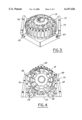
- FIG. 3 is a perspective view of a stator housing formed according to the present invention.
- FIG. 4 is a side view of the stator housing of FIG. 3.
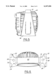
- FIG. 5 is a side view of the stator housing of FIG. 3.
- FIG. 6 is an end view of the alternator housing of FIG. 4.
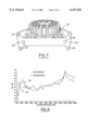
- FIG. 7 is an end view of an alternative embodiment of a stator housing according to the present invention.
- FIG. 8 is a plot of sound versus speed for an alternator not using the mounting portion of the present invention and an alternator having an improved mounting portion.
- the present invention is particularly directed to reducing 36 th order magnetic noise in an alternator.
- the present invention may also reduce other types of noise and may also be suitable for other rotating electrical machines.
- an automotive vehicle 10 has an engine 12 with an alternator 14 coupled thereto.
- Engine 12 has a belt 13 that is used to rotate the alternator 14.
- the rotating alternator 14 is used to generate electrical energy for the vehicle 10.
- FIG. 2 a portion of engine 12 is shown having a flat portion 16 against which alternator 14 is mounted.
- a bolt 17 or other fastener may be used to secure alternator 14 to engine 12.
- Alternator 14 is shown having a stator housing comprised of a plurality of hollow elements 18, 20 and 22.
- Housing element 18 is a generally cup-shaped casting about a central axis 24.
- Housing element 12 retains a relatively fixed stator assembly (not shown) and also surrounds a rotor (not shown) mounted on shaft 26.
- the shaft 26 is supported for rotation in the hollow element 18 and in a bearing support 28.
- hollow element 18 surrounds the stator and the rotor portions of alternator 14.
- the rotor is rotationally driven on pulley 30 to generate alternating current.
- Hollow element 18 is generally cylindrically shaped and is mated along its edge to hollow elements 20 and 22.
- a mounting portion 32 is circumferentially positioned at least a portion around hollow element 18. As will be illustrated below, mounting portion 32 may have mounting pads 34 positioned between mounting portion 32 and engine 12. Mounting portion 32 is preferably integrally formed with hollow element 18. However, mounting portion 32 may be a separate component.
- mounting portion 32 is illustrated as having a generally pentagonal shape and extends completely around hollow element 18. Other suitable shapes would be evident to those skilled in the art.
- Mounting portion 32 has a first securing portion 36 and a second securing portion 38 positioned on opposite sides of hollow element 18.
- First securing portion 36 and second securing portion 38 are generally triangular in shape in two dimensions. As best shown in FIG. 5, an end view of first securing portion 36 is generally triangular in shape. Also, as is best shown in FIG. 6, an end view of first securing portion 36 and second securing portion 38 have a respective first through channel 40 and a second through channel 42.
- the first through channel 40 and second through channel 42 are located on opposite sides of hollow element 18 and are used for securing the mounting portion 32 and thus the alternator 14 to engine 12. That is, first securing portion 36 and second securing portion 38 are radially opposite each other.
- First through channel 40 and second through channel 42 are parallel with each other and are substantially tangential to hollow element 18. The direction of first through channel 40 and second through channel 42 is perpendicular to the central axis 24 of alternator 14 and hollow element 18.
- Mounting portion 32 has a bridge portion 44 extending around a portion of hollow element 18 between first securing portion 36 and second securing portions 38.
- Bridge portion 44 is coupled between the upper portion 46 of first securing portion 36 and an upper portion 48 of second securing portion 38.
- Upper portion 46 and upper portion 48 correspond to the vertex of the triangle shape of first securing portion 36 and second securing portion 38.
- the bridge portion 44 corresponds to the top of the generally pentagonal shape of the mounting portion 32 and is positioned opposite the engine.
- Mounting portion 32 has a lower portion 50 that extends at least partially around hollow element 18 on the opposite side of hollow element 18 as bridge portion 44.
- Lower portion 50 has a generally flat side 52 that may be positioned adjacent to engine 12. Although, for mounting purposes, flat side 52 may be spaced apart from engine 12 by mounting pads 34, as will be further described below.
- Lower portion 50 extends about 180° around hollow element 18.
- recesses 54 having a reduced thickness may be provided. Although a total of six recesses are illustrated, a greater number of recesses to further reduce weight may be employed on mounting portion 32. However, the amount of reduction should still allow sufficient strength in portion 32. Recesses 54 may also extend completely through portion 32 to further reduce weight.
- First securing portion 36 and second securing portion 38 have mounting pads 34 positioned thereon. Each of first securing portion 36 and second securing portion 38 have three mounting pads 34 positioned in a generally triangular shape. Mounting pads 34 preferably extend about 1 millimeter from the first securing portion and second securing portion 38. Each of the mounting pads 34 is generally on the same plane to provide a mounting surface against engine 12. The area of the mounting pads 34 may vary depending on the area of engine for mounting.
- First through channel 40 and second through channel 42 are preferably positioned at a centroid of the three mounting pads 34 on each respective securing portions 36, 38.
- the fastener is thus located at the centroid. This arrangement has been found to provide sufficient holding characteristics as well as reduced noise characteristics. It is believed that an even holding distribution is divided across pads 34.
- FIG. 7 a perspective view of an alternative embodiment of mounting portion 32' is illustrated.
- the mounting pads 34 from above are eliminated and the first through channel 40 and second through channel 42 have been replaced by first group 60 of three through channels 62 and a second group 64 of through channels 66.
- Through channels 62, 66 are preferably positioned near the corners of respective first securing portions 36 and second securing portion 38.
- a fastener (shown above in FIG. 2) is positioned within each through channel 62, 64 to secure alternator 14 to engine 12.
- a sound level signal 70 of an alternator without the present invention is illustrated for comparison to a sound level signal 72 of an alternator according to the teachings of the present invention.
- the sound level particularly 36 th order noise, is substantially reduced using the mounting portion of the present invention.
Abstract
Description
Claims (22)
Priority Applications (2)
| Application Number | Priority Date | Filing Date | Title |
|---|---|---|---|
| US09/430,576 US6147426A (en) | 1999-10-29 | 1999-10-29 | Housing and mounting portion for an alternator |
| GB0024458A GB2358739A (en) | 1999-10-29 | 2000-10-06 | A housing and mounting portion for an alternator |
Applications Claiming Priority (1)
| Application Number | Priority Date | Filing Date | Title |
|---|---|---|---|
| US09/430,576 US6147426A (en) | 1999-10-29 | 1999-10-29 | Housing and mounting portion for an alternator |
Publications (1)
| Publication Number | Publication Date |
|---|---|
| US6147426A true US6147426A (en) | 2000-11-14 |
Family
ID=23708149
Family Applications (1)
| Application Number | Title | Priority Date | Filing Date |
|---|---|---|---|
| US09/430,576 Expired - Fee Related US6147426A (en) | 1999-10-29 | 1999-10-29 | Housing and mounting portion for an alternator |
Country Status (2)
| Country | Link |
|---|---|
| US (1) | US6147426A (en) |
| GB (1) | GB2358739A (en) |
Cited By (17)
| Publication number | Priority date | Publication date | Assignee | Title |
|---|---|---|---|---|
| US6750578B2 (en) | 2002-07-22 | 2004-06-15 | Delphi Technologies, Inc. | Rotating electrical machine |
| US20050062349A1 (en) * | 2003-09-22 | 2005-03-24 | Denso Corporation | Alternator for a vehicle |
| US20060090554A1 (en) * | 2004-10-29 | 2006-05-04 | Scott Krampitz | Alternator holding apparatus and method for alternator testing |
| US20060092584A1 (en) * | 2004-10-29 | 2006-05-04 | Spx Corporation | Alternator and starter tester protection apparatus and method |
| US20060090551A1 (en) * | 2004-10-29 | 2006-05-04 | Jason Murphy | Door interlock apparatus and method for alternator/starter bench testing device |
| US20060091597A1 (en) * | 2004-10-29 | 2006-05-04 | Scott Opsahl | Vertical alternator holding apparatus and method for alternator testing |
| US20060136119A1 (en) * | 2004-10-29 | 2006-06-22 | Kurt Raichle | Alternator and starter tester apparatus and method |
| US20060226720A1 (en) * | 2005-01-28 | 2006-10-12 | Motorcar Parts Of America, Inc. | Illuminated alternator and method of operation |
| US20060255666A1 (en) * | 2005-05-12 | 2006-11-16 | Williams Donald J | Resilient isolation members and related methods of reducing acoustic noise and/or structural vibration in an electric machine |
| US20080016983A1 (en) * | 2004-07-28 | 2008-01-24 | Dietmar Saur | Intermediate Flange for a Machine Tool |
| US20080023547A1 (en) * | 2006-07-27 | 2008-01-31 | Spx Corporation | Alternator and starter tester with bar code functionality and method |
| US8903595B2 (en) | 2012-09-17 | 2014-12-02 | Bosch Automotive Service Solutions Llc | Alternator and starter tester with increased load and cable identification |
| US9128156B2 (en) | 2012-05-03 | 2015-09-08 | Bosch Automotive Service Solutions Inc. | Alternator and starter tester with other failures determination functionality and method |
| US9797956B2 (en) | 2015-11-24 | 2017-10-24 | Bosch Automotive Service Solutions Inc. | System and method for testing alternator default mode operation |
| US10055711B2 (en) | 2012-02-22 | 2018-08-21 | Bosch Automotive Service Solutions Inc. | Alternator and starter tester with warranty code functionality and method |
| US10193413B2 (en) | 2015-12-15 | 2019-01-29 | Bosch Automotive Service Solutions Inc. | Mounting bracket for water cooled type alternator |
| US11598695B2 (en) | 2019-09-23 | 2023-03-07 | Dana Monroe | Alternator and starter motor test fixture |
Citations (10)
| Publication number | Priority date | Publication date | Assignee | Title |
|---|---|---|---|---|
| US4849665A (en) * | 1987-02-26 | 1989-07-18 | Mitsubishi Denki Kabushiki Kaisha | Anti-vibration mounting for vehicle alternator |
| US4980589A (en) * | 1988-09-21 | 1990-12-25 | Mitsubishi Denki Kabushiki Kaisha | Vehicle alternator with adaptable mounting bracket |
| JPH04351442A (en) * | 1991-05-28 | 1992-12-07 | Hitachi Ltd | Ac generator for vehicle |
| US5210453A (en) * | 1991-01-25 | 1993-05-11 | Ford Motor Company | Through bolt resonance suppression in an alternator |
| US5394039A (en) * | 1993-01-19 | 1995-02-28 | Ryobi Outdoor Products Inc. | Electric motor mount having vibration damping |
| US5397950A (en) * | 1993-12-23 | 1995-03-14 | Cary Products Co., Inc. | Isolation motor mount and gasket |
| US5686773A (en) * | 1994-06-20 | 1997-11-11 | Nippondenso Co., Ltd. | Alternator with generally triangular engine-mounting stays |
| US5696415A (en) * | 1994-06-07 | 1997-12-09 | Nippondenso Co., Ltd. | Electric rotary machine |
| US5760513A (en) * | 1996-08-26 | 1998-06-02 | Mitsubishi Denki Kabushiki Kaisha | AC Generator for vehicle and method of assembling the same |
| US5914549A (en) * | 1996-01-08 | 1999-06-22 | Mitsubishi Denki Kabushiki Kaisha | Alternator for motor vehicles and manufacturing method thereof |
Family Cites Families (3)
| Publication number | Priority date | Publication date | Assignee | Title |
|---|---|---|---|---|
| US4033531A (en) * | 1976-04-27 | 1977-07-05 | Fred Levine | Mounting assembly with selectively used one-piece or two-piece brackets |
| DE2648809C2 (en) * | 1976-10-27 | 1978-12-14 | Dipl.-Ing. Hitzinger & Co., Linz (Oesterreich) | Electric machine |
| US5752688A (en) * | 1996-09-10 | 1998-05-19 | Emerson Electric Co. | Support assembly that is selectively repositionable and attachable to different sides of an air cooled machine housing |
-
1999
- 1999-10-29 US US09/430,576 patent/US6147426A/en not_active Expired - Fee Related
-
2000
- 2000-10-06 GB GB0024458A patent/GB2358739A/en not_active Withdrawn
Patent Citations (10)
| Publication number | Priority date | Publication date | Assignee | Title |
|---|---|---|---|---|
| US4849665A (en) * | 1987-02-26 | 1989-07-18 | Mitsubishi Denki Kabushiki Kaisha | Anti-vibration mounting for vehicle alternator |
| US4980589A (en) * | 1988-09-21 | 1990-12-25 | Mitsubishi Denki Kabushiki Kaisha | Vehicle alternator with adaptable mounting bracket |
| US5210453A (en) * | 1991-01-25 | 1993-05-11 | Ford Motor Company | Through bolt resonance suppression in an alternator |
| JPH04351442A (en) * | 1991-05-28 | 1992-12-07 | Hitachi Ltd | Ac generator for vehicle |
| US5394039A (en) * | 1993-01-19 | 1995-02-28 | Ryobi Outdoor Products Inc. | Electric motor mount having vibration damping |
| US5397950A (en) * | 1993-12-23 | 1995-03-14 | Cary Products Co., Inc. | Isolation motor mount and gasket |
| US5696415A (en) * | 1994-06-07 | 1997-12-09 | Nippondenso Co., Ltd. | Electric rotary machine |
| US5686773A (en) * | 1994-06-20 | 1997-11-11 | Nippondenso Co., Ltd. | Alternator with generally triangular engine-mounting stays |
| US5914549A (en) * | 1996-01-08 | 1999-06-22 | Mitsubishi Denki Kabushiki Kaisha | Alternator for motor vehicles and manufacturing method thereof |
| US5760513A (en) * | 1996-08-26 | 1998-06-02 | Mitsubishi Denki Kabushiki Kaisha | AC Generator for vehicle and method of assembling the same |
Cited By (35)
| Publication number | Priority date | Publication date | Assignee | Title |
|---|---|---|---|---|
| US6750578B2 (en) | 2002-07-22 | 2004-06-15 | Delphi Technologies, Inc. | Rotating electrical machine |
| US7078836B2 (en) * | 2003-09-22 | 2006-07-18 | Denso Corporation | Alternator for a vehicle |
| US20050062349A1 (en) * | 2003-09-22 | 2005-03-24 | Denso Corporation | Alternator for a vehicle |
| US20080016983A1 (en) * | 2004-07-28 | 2008-01-24 | Dietmar Saur | Intermediate Flange for a Machine Tool |
| US8310271B2 (en) | 2004-10-29 | 2012-11-13 | Spx Corporation | Starter zero current test apparatus and method |
| US20100170944A1 (en) * | 2004-10-29 | 2010-07-08 | Kurt Raichle | Alternator and Starter Tester with Bar Code Functionality and Method |
| US20060136119A1 (en) * | 2004-10-29 | 2006-06-22 | Kurt Raichle | Alternator and starter tester apparatus and method |
| US20060090551A1 (en) * | 2004-10-29 | 2006-05-04 | Jason Murphy | Door interlock apparatus and method for alternator/starter bench testing device |
| US20060092584A1 (en) * | 2004-10-29 | 2006-05-04 | Spx Corporation | Alternator and starter tester protection apparatus and method |
| US7134324B2 (en) * | 2004-10-29 | 2006-11-14 | Spx Corporation | Alternator holding apparatus and method for alternator testing |
| US20090249868A1 (en) * | 2004-10-29 | 2009-10-08 | Spx Corporation | Starter Zero Current Test Apparatus and Method |
| US8226008B2 (en) | 2004-10-29 | 2012-07-24 | Spx Corporation | Alternator and starter tester with bar code functionality and method |
| US7150186B2 (en) | 2004-10-29 | 2006-12-19 | Spx Corporation | Door interlock apparatus and method for alternator/starter bench testing device |
| US20060091597A1 (en) * | 2004-10-29 | 2006-05-04 | Scott Opsahl | Vertical alternator holding apparatus and method for alternator testing |
| US7212911B2 (en) | 2004-10-29 | 2007-05-01 | Spx Corporation | Alternator and starter tester apparatus and method |
| US20070152702A1 (en) * | 2004-10-29 | 2007-07-05 | Kurt Raichle | Starter zero current test apparatus and method |
| US7300041B2 (en) | 2004-10-29 | 2007-11-27 | Spx Corporation | Vertical alternator holding apparatus and method for alternator testing |
| US20060090554A1 (en) * | 2004-10-29 | 2006-05-04 | Scott Krampitz | Alternator holding apparatus and method for alternator testing |
| US7696759B2 (en) | 2004-10-29 | 2010-04-13 | Spx Corporation | Alternator and starter tester with alternator cable check |
| US7336462B2 (en) | 2004-10-29 | 2008-02-26 | Spx Corporation | Alternator and starter tester protection apparatus and method |
| US20090039898A1 (en) * | 2004-10-29 | 2009-02-12 | Spx Corporation | Alternator and starter tester with alternator cable check |
| US7538571B2 (en) | 2004-10-29 | 2009-05-26 | Spx Corporation | Starter zero current test apparatus and method |
| US20060226720A1 (en) * | 2005-01-28 | 2006-10-12 | Motorcar Parts Of America, Inc. | Illuminated alternator and method of operation |
| US7604374B2 (en) * | 2005-01-28 | 2009-10-20 | Motorcar Parts Of America, Inc. | Illuminated alternator and method of operation |
| US7196438B2 (en) | 2005-05-12 | 2007-03-27 | Emerson Electric Co. | Resilient isolation members and related methods of reducing acoustic noise and/or structural vibration in an electric machine |
| WO2006124735A1 (en) * | 2005-05-12 | 2006-11-23 | Emerson Electric Co. | Resilient isolation members and related methods of reducing acoustic noise and/or structural vibration in an electric machine |
| US20060255666A1 (en) * | 2005-05-12 | 2006-11-16 | Williams Donald J | Resilient isolation members and related methods of reducing acoustic noise and/or structural vibration in an electric machine |
| US7690573B2 (en) | 2006-07-27 | 2010-04-06 | Spx Corporation | Alternator and starter tester with bar code functionality and method |
| US20080023547A1 (en) * | 2006-07-27 | 2008-01-31 | Spx Corporation | Alternator and starter tester with bar code functionality and method |
| US10055711B2 (en) | 2012-02-22 | 2018-08-21 | Bosch Automotive Service Solutions Inc. | Alternator and starter tester with warranty code functionality and method |
| US9128156B2 (en) | 2012-05-03 | 2015-09-08 | Bosch Automotive Service Solutions Inc. | Alternator and starter tester with other failures determination functionality and method |
| US8903595B2 (en) | 2012-09-17 | 2014-12-02 | Bosch Automotive Service Solutions Llc | Alternator and starter tester with increased load and cable identification |
| US9797956B2 (en) | 2015-11-24 | 2017-10-24 | Bosch Automotive Service Solutions Inc. | System and method for testing alternator default mode operation |
| US10193413B2 (en) | 2015-12-15 | 2019-01-29 | Bosch Automotive Service Solutions Inc. | Mounting bracket for water cooled type alternator |
| US11598695B2 (en) | 2019-09-23 | 2023-03-07 | Dana Monroe | Alternator and starter motor test fixture |
Also Published As
| Publication number | Publication date |
|---|---|
| GB2358739A (en) | 2001-08-01 |
| GB0024458D0 (en) | 2000-11-22 |
Similar Documents
| Publication | Publication Date | Title |
|---|---|---|
| US6147426A (en) | Housing and mounting portion for an alternator | |
| US5828155A (en) | Alternating current generator | |
| GB2281665A (en) | Mounting magnets in a rotor for an AC generator | |
| JP2009148057A (en) | Ac generator for vehicle | |
| EP0687052B1 (en) | Electric rotary machine | |
| US6617717B2 (en) | Alternator | |
| US6707181B1 (en) | Alternator fan | |
| US4614889A (en) | Charging dynamoelectric machine having reduced noise output | |
| JPH03159549A (en) | Ac generator for automobile use | |
| JPH11506000A (en) | Rotary electric machine | |
| JP3789361B2 (en) | AC generator | |
| JP3876912B2 (en) | AC generator for vehicles | |
| US4102601A (en) | Forced draft fan blade construction for dynamo electric machines and forced draft automotive alternator | |
| JP3294497B2 (en) | Alternator | |
| KR100557409B1 (en) | Automotive alternator having housing for reducing cooling fan noise | |
| FR2981809A1 (en) | FASTENING ELEMENT FOR ELECTRIC MACHINES | |
| JP3794523B2 (en) | AC alternator rotor for vehicles | |
| JP3656347B2 (en) | Rotating machine rotor | |
| JPH0823660A (en) | Alternator for vehicle | |
| JPH01318532A (en) | Rotor of brushless ac generator | |
| JP3644126B2 (en) | AC generator | |
| KR100308953B1 (en) | Alternator | |
| JPH0622482A (en) | Rotor of dynamo-electric machine for vehicle | |
| KR20180034997A (en) | Motor | |
| JP3446938B2 (en) | Landel type pole core for vehicle alternator |
Legal Events
| Date | Code | Title | Description |
|---|---|---|---|
| AS | Assignment |
Owner name: FORD MOTOR COMPANY, MICHIGAN Free format text: ASSIGNMENT OF ASSIGNORS INTEREST;ASSIGNORS:LEPI, STEVEN M.;SWALES, SHAWN;REEL/FRAME:010368/0666 Effective date: 19991022 |
|
| AS | Assignment |
Owner name: VISTEON GLOBAL TECHNOLOGIES, INC., MICHIGAN Free format text: ASSIGNMENT OF ASSIGNORS INTEREST;ASSIGNOR:FORD MOTOR COMPANY;REEL/FRAME:010968/0220 Effective date: 20000615 |
|
| REMI | Maintenance fee reminder mailed | ||
| LAPS | Lapse for failure to pay maintenance fees | ||
| LAPS | Lapse for failure to pay maintenance fees |
Free format text: PATENT EXPIRED FOR FAILURE TO PAY MAINTENANCE FEES (ORIGINAL EVENT CODE: EXP.); ENTITY STATUS OF PATENT OWNER: LARGE ENTITY |
|
| STCH | Information on status: patent discontinuation |
Free format text: PATENT EXPIRED DUE TO NONPAYMENT OF MAINTENANCE FEES UNDER 37 CFR 1.362 |
|
| FP | Lapsed due to failure to pay maintenance fee |
Effective date: 20041114 |