US6131748A - Article display device - Google Patents

Article display device Download PDF

Info

Publication number
US6131748A
US6131748A US09/068,105 US6810598A US6131748A US 6131748 A US6131748 A US 6131748A US 6810598 A US6810598 A US 6810598A US 6131748 A US6131748 A US 6131748A
Authority
US
United States
Prior art keywords
bar
article display
present
article
urging body
Prior art date
Legal status (The legal status is an assumption and is not a legal conclusion. Google has not performed a legal analysis and makes no representation as to the accuracy of the status listed.)
Expired - Lifetime
Application number
US09/068,105
Inventor
Junzaburo Kawasaki
Hideaki Kawamura
Akihiko Endo
Current Assignee (The listed assignees may be inaccurate. Google has not performed a legal analysis and makes no representation or warranty as to the accuracy of the list.)
Kawajun Co Ltd
Original Assignee
Kawajun Co Ltd
Priority date (The priority date is an assumption and is not a legal conclusion. Google has not performed a legal analysis and makes no representation as to the accuracy of the date listed.)
Filing date
Publication date
Priority claimed from JP31860495A external-priority patent/JP3166821B2/en
Priority claimed from JP5164896A external-priority patent/JPH09238791A/en
Application filed by Kawajun Co Ltd filed Critical Kawajun Co Ltd
Assigned to KAWAJUN CO., LTD., KAWASAKI, JUNZABURO reassignment KAWAJUN CO., LTD. ASSIGNMENT OF ASSIGNORS INTEREST (SEE DOCUMENT FOR DETAILS). Assignors: ENDO, AKIHIKO, KAWAMURA, HIDEAKI, KAWASAKI, JUNZABURO
Application granted granted Critical
Publication of US6131748A publication Critical patent/US6131748A/en
Anticipated expiration legal-status Critical
Expired - Lifetime legal-status Critical Current

Links

Images

Classifications

    • AHUMAN NECESSITIES
    • A47FURNITURE; DOMESTIC ARTICLES OR APPLIANCES; COFFEE MILLS; SPICE MILLS; SUCTION CLEANERS IN GENERAL
    • A47FSPECIAL FURNITURE, FITTINGS, OR ACCESSORIES FOR SHOPS, STOREHOUSES, BARS, RESTAURANTS OR THE LIKE; PAYING COUNTERS
    • A47F1/00Racks for dispensing merchandise; Containers for dispensing merchandise
    • A47F1/04Racks or containers with arrangements for dispensing articles, e.g. by means of gravity or springs
    • A47F1/12Racks or containers with arrangements for dispensing articles, e.g. by means of gravity or springs dispensing from the side of an approximately horizontal stack
    • A47F1/125Racks or containers with arrangements for dispensing articles, e.g. by means of gravity or springs dispensing from the side of an approximately horizontal stack with an article-pushing device
    • A47F1/128Racks or containers with arrangements for dispensing articles, e.g. by means of gravity or springs dispensing from the side of an approximately horizontal stack with an article-pushing device for article hangers or brackets
    • AHUMAN NECESSITIES
    • A47FURNITURE; DOMESTIC ARTICLES OR APPLIANCES; COFFEE MILLS; SPICE MILLS; SUCTION CLEANERS IN GENERAL
    • A47FSPECIAL FURNITURE, FITTINGS, OR ACCESSORIES FOR SHOPS, STOREHOUSES, BARS, RESTAURANTS OR THE LIKE; PAYING COUNTERS
    • A47F5/00Show stands, hangers, or shelves characterised by their constructional features
    • A47F5/08Show stands, hangers, or shelves characterised by their constructional features secured to the wall, ceiling, or the like; Wall-bracket display devices
    • A47F5/0807Display panels, grids or rods used for suspending merchandise or cards supporting articles; Movable brackets therefor
    • A47F5/0815Panel constructions with apertures for article supports, e.g. hooks
    • A47F5/0823Article supports for peg-boards
    • AHUMAN NECESSITIES
    • A47FURNITURE; DOMESTIC ARTICLES OR APPLIANCES; COFFEE MILLS; SPICE MILLS; SUCTION CLEANERS IN GENERAL
    • A47FSPECIAL FURNITURE, FITTINGS, OR ACCESSORIES FOR SHOPS, STOREHOUSES, BARS, RESTAURANTS OR THE LIKE; PAYING COUNTERS
    • A47F5/00Show stands, hangers, or shelves characterised by their constructional features
    • A47F5/08Show stands, hangers, or shelves characterised by their constructional features secured to the wall, ceiling, or the like; Wall-bracket display devices
    • A47F5/0807Display panels, grids or rods used for suspending merchandise or cards supporting articles; Movable brackets therefor
    • A47F5/0869Accessories for article-supporting brackets, e.g. price- indicating means, not covered by a single one of groups A47F5/08

Definitions

  • the present invention relates to an article display device which is suitable for displaying a large number of articles in a suspended state such that the articles are always aligned orderly at the forefront on article display bars of an article display rack in a supermarket, a drugstore, and so on.
  • an article display device for use in an article display rack in a supermarket, a drugstore, or the like is composed of an engaging piece, which may be removably or unremovably attached to a bar member of the article display rack; an article display bar having the rear end secured to the engaging piece and the front end inclined upwardly; and a supporting bar positioned above the article display bar, to which a display plate is attached at the front end thereof and which is linked to the rear end of the article display bar.
  • the present invention provide an article display device characterized by comprising an engaging piece removably or unremovably attached to a bar member of an article display rack, an article display bar having a rear end fixed to the engaging piece, a supporting bar positioned above the article display bar and linked to the engaging piece or to the rear end of the article display bar, an urging body slidably attached to the supporting bar for urging articles supported by the article display bar to the front, and means for sliding the urging body.
  • the present invention also provides the article display device which comprises a resilient body for always urging the urging body to the rear.
  • the present invention also provides the article display device which comprises an article arrangement correcting member attached to the front end of the supporting bar and abutting an article at the forefront supported by the article display bar.
  • the present invention further provides an article display device characterized by comprising an engaging piece removably or unremovably attached to a bar member of an article display rack, an article display bar having a non-circular cross-section and a rear end fixed to the engaging piece, an urging body non-rotatably and slidably attached to the article display bar and capable of urging articles supported by the article display bar to the front, and a supporting bar having a rear end fixed to the urging body and a front end to which a display plate is attached, and positioned above the article display bar.
  • the present invention further provides an article display device characterized by comprising an engaging piece removably or unremovably attached to a bar member of an article display rack, an article display bar having a rear end fixed to the engaging piece, a supporting bar positioned above the article display bar, integrally formed with the engaging piece or the rear end of the article display bar, an urging body slidably attached to the article display bar and capable of urging articles supported by the article display bar, and a pushing mechanism for always pushing the urging body to the front.
  • FIG. 1 illustrates a front view of a first embodiment of the present invention in a used state
  • FIG. 2 illustrates a cross-sectional view of a main portion of the first embodiment of the present invention in a used state when viewed from a side;
  • FIG. 3 illustrates a side view of the first embodiment of the present invention in a used state
  • FIG. 4 illustrates a plan view of the first embodiment of the present invention in a used state
  • FIG. 5 illustrates a front view of the first embodiment of the present invention in a used state
  • FIG. 6 illustrates an explanatory diagram for a state in which a manipulation bar is actuated in the first embodiment of the present invention
  • FIG. 7 illustrates a side view of a second embodiment of the present invention in a used state
  • FIG. 8 illustrates a plan view of the second embodiment of the present invention in a used state
  • FIG. 9 illustrates a side view of a third embodiment of the present invention in a used state
  • FIG. 10 illustrates a plan view of the third embodiment of the present invention in a used state
  • FIG. 11 illustrates a side view of a fourth embodiment of the present invention in a used state
  • FIG. 12 illustrates a plan view of the fourth embodiment of the present invention in a used state
  • FIG. 13 illustrates a side view of a fifth embodiment of the present invention in a used state
  • FIG. 14 illustrates a plan view of the fifth embodiment of the present invention in a used state
  • FIG. 15 illustrates a side view of a sixth embodiment of the present invention in a used state
  • FIG. 16 illustrates a plan view of the sixth embodiment of the present invention in a used state
  • FIG. 17 illustrates a partially cross-sectioned side view of a seventh embodiment of the present invention in a used state
  • FIG. 18 illustrates a plan view of the seventh embodiment of the present invention in a used state
  • FIG. 19 illustrates a partially cross-sectioned side view of an eighth embodiment of the present invention in a used state
  • FIG. 20 illustrates a plan view of the eighth embodiment of the present invention in a used state
  • FIG. 21 illustrates a partially cross-sectioned side view of a ninth embodiment of the present invention in a used state
  • FIG. 22 illustrates a plan view of the ninth embodiment of the present invention in a used state
  • FIG. 23 illustrates a side view of a tenth embodiment of the present invention in a used state
  • FIG. 24 illustrates a plan view of the tenth embodiment of the present invention in a used state
  • FIG. 25 illustrates a side view of an eleventh embodiment of the present invention in a used state
  • FIG. 26 illustrates a plan view of the eleventh embodiment of the present invention in a used state
  • FIG. 27 illustrates a partial side view of a twelfth embodiment of the present invention in a used state
  • FIG. 28 illustrates a plan view of the twelfth embodiment of the present invention in a used state
  • FIG. 29 illustrates a side view of a thirteenth embodiment of the present invention in a used state
  • FIG. 30 illustrates a plan view of the thirteenth embodiment of the present invention in a used state
  • FIG. 31 illustrates a perspective view of a fourteenth embodiment of the present invention in a used state
  • FIG. 32 illustrates a perspective view of a fifteenth embodiment of the present invention in a used state
  • FIG. 33 illustrates a perspective view of a sixteenth embodiment of the present invention in a used state
  • FIG. 34 illustrates a side view of FIG. 33 in a used state
  • FIG. 35 illustrates a cross-sectional view taken along a line A--A in FIG. 33;
  • FIG. 36 illustrates an exploded view illustrating the structure of a seventeenth embodiment of the present invention.
  • FIGS. 37 and 38 illustrate partially cross-sectioned front views of an eighteenth embodiment of the present invention in a used state
  • FIG. 39 illustrates a partially cut-away perspective view showing the eighteenth embodiment of the present invention.
  • FIG. 40 illustrates a cross-sectional view for explaining a stopper means in the eighteenth embodiment of the present invention.
  • reference numeral 1 designates an article display device of the present invention; 3 a bar member; 4 an engaging piece; 6 an article display bar; 7 a supporting bar; 9 a display plate; and 12 an urging body, respectively.
  • FIGS. 1-6 designates an article display device of the present invention which is removably attached to a bar member 3 of an article display rack 2.
  • This article display device 1 comprises a channel-like engaging piece 4 removably attached to the bar member 3; an article display bar 6 having the rear end secured to the engaging piece 4 by welding or the like and the front end inclined upwardly for suspending a large number of packaged articles 5; a supporting bar 7, positioned above the article display bar 6, having the rear end integrally formed with the engaging piece 4 or the rear end of the article display bar 6, in this embodiment, linked with the article display bar 6; a display plate 9 fitted on a front end portion of the supporting bar 7, on which a display card 8 can be securely adhered; an urging body 12, formed with an inserting hole 10 into which the supporting bar 7 is inserted, slidably suspended on the supporting bar 7 to have the ability of urging the articles 5 suspended on article display bar 6 , and having an elongated article display bar inserting hole 11; and means for
  • the packaged articles 5 are loaded onto the article display bar 6 in a suspended state from the front end thereof and pushed toward the rear as illustrated in FIG. 3, whereby the urging body 12 is slid on the supporting bar 7 and positioned in the rear.
  • the handle 16 of the manipulation bar 17 is held and pulled out, as illustrated in FIG. 6, to slide the urging body 12 to the front such that the articles 5 are extruded to the front.
  • FIGS. 7-40 different embodiments of the present invention illustrated in FIGS. 7-40 will be described.
  • the same constituents as those in the foregoing first embodiment of the present invention are designated the same reference numerals, and repetitive explanation is omitted.
  • a second embodiment of the present invention in FIGS. 7 and 8 differs from the foregoing first embodiment of the present invention mainly in that the rear end of the manipulation bar 17 is secured to the urging body 12, and an article display device 1A thus constructed also has similar meritorious effects to the foregoing first embodiment of the present invention.
  • a third embodiment of the present invention in FIGS. 9 and 10 differs from the foregoing second embodiment of the present invention mainly in that a supporting bar 7A composed of two parallelly arranged bar members 7a, 7a are used, and an article display device 1B thus constructed also has similar meritorious effects to the foregoing second embodiment of the present invention.
  • a fourth embodiment of the present invention in FIGS. 11 and 12 differs from the foregoing first embodiment mainly in that a wire is used to form a manipulation bar 17 having an urging body 12A formed in a rear end portion, and a sandwiching member 19 is formed for supporting a supporting bar 7, in a sandwiching form, to a supporting member 18 for slidably supporting the manipulation bar 17.
  • An article display device 1C thus constructed also has similar meritorious effects to the foregoing second embodiment of the present invention.
  • a fifth embodiment of the present invention in FIGS. 13 and 14 differs from the foregoing first embodiment of the present invention mainly in that a resilient body 20, a tension spring in this embodiment, is interposed between the rear end of a manipulation bar 17 and the rear end of a supporting bar 7 such that the manipulation bar 17 may be always positioned in a retracted state.
  • An article display device 1D thus constructed also has similar meritorious effects to the foregoing first embodiment of the present invention.
  • a sixth embodiment of the present invention in FIGS. 15 and 16 differs from the foregoing second embodiment mainly in that a manipulation bar 17 having an urging body 12A formed integrally therewith at the rear end may be always positioned in a retracted state with a tension spring 20.
  • An article display device 1E thus constructed also has similar meritorious effects to the foregoing second embodiment of the present invention.
  • a seventh embodiment of the present invention in FIGS. 17 and 18 differs from the foregoing first embodiment of the present invention mainly in that an urging body 12 is automatically slid.
  • the urging body 12 is provided with a fixed load spring 21 for always moving the urging body 12 forwardly with a predetermined pushing pressure.
  • An article display device 1F thus constructed also has similar meritorious effects to the foregoing first embodiment, and in addition, can automatically urge articles 5 forwardly.
  • FIGS. 19 and 20 differs from the foregoing seventh embodiment of the present invention mainly in that a display plate 9 is provided with a fixed load spring 21, and an article display device 1G thus constructed also has similar meritorious effects to the foregoing seventh embodiment of the present invention.
  • a ninth embodiment of the present invention in FIGS. 21 and 22 differs from the foregoing second embodiment of the present invention mainly in that an urging body 12 is attached to a position near the rear end of a movable display plate supporting bar 24, which has a display plate 9 at the front end thereof, slidably attached to a supporting bar 23.
  • a supporting bar 7B is composed of the cylindrical fixed supporting bar 23 having a guide groove 22 fixed to an engaging piece 4 and the movable display plate supporting bar 24, onto which the display plate 9 is fixedly fitted on a front end portion, slidably attached to the fixed supporting bar 23, and the urging body 12, which moves along the guide groove 22 of the fixed supporting bar 23, is secured to the rear end of the movable display plate supporting bar 24 of the supporting bar 7B.
  • An article display device 1H thus constructed also has similar meritorious effects to the foregoing second embodiment of the present invention.
  • a tenth embodiment of the present invention in FIGS. 23 and 24 differs from the foregoing ninth embodiment of the present invention mainly in that the former employs a rod-like fixed supporting bar 23A, and also employs a supporting bar 7C which includes a cylindrical member serving as a movable display plate supporting bar 24A which is slidably attached to the fixed supporting bar 23A.
  • An article display device 1I thus constructed also has similar meritorious effects to the foregoing ninth embodiment of the present invention.
  • FIGS. 25 and 26 differs from the foregoing first embodiment of the present invention mainly in that a supporting bar 7 is inclined downwardly toward the front end such that an urging body 12 always slides to the front.
  • An article display device 1J thus constructed also has similar meritorious effects to the foregoing first embodiment of the present invention.
  • a twelfth embodiment of the present invention in FIGS. 27 and 28 differs from the foregoing first embodiment of the present invention mainly in that an article display bar 6A having a non-circular cross-section, or a rectangular cross-section in this embodiment, and a supporting bar 7D having the rear end secured to an urging body 12B non-rotatably but slidably attached to the article display bar 6A are employed.
  • An article display device 1K thus constructed also has similar meritorious effects to the foregoing first embodiment of the present invention, and can provide a simpler structure.
  • the article display bar 6A may be non-circular in cross-section and have a shaft which is elliptic, polygonal, or non-circular in cross section and formed with a guide piece, a guide groove, or the like.
  • a thirteenth embodiment of the present invention in FIGS. 29 and 30 differs from the foregoing first embodiment of the present invention mainly in that a slidable urging body 12 is attached to an article display bar 6, and a pressure applying mechanism 27 using a link 26 for always pushing the urging body 12 to the front with a spring 25 is attached to the urging body 12 and an engaging piece 4.
  • An article display device 1L thus constructed also has similar meritorious effects to the foregoing first embodiment of the present invention, and in addition, can always push articles 5 to the front.
  • a fourteenth embodiment of the present invention in FIG. 31 differs from the foregoing first embodiment of the present invention mainly in that an urging body 12 automatically pushes articles 5 supported by an article display bar 6 with a tension force of a spring coil 28, and an article arrangement correcting member 29 is rotatably (omitted in the figures) disposed at the front end of a supporting bar 7 through a supporting block 30 for also preventing articles from dropping.
  • the urging body 12 comprises guiding portions 121, 122 slidable on the supporting bar 7 and the article display bar 6, and is automatically pushed to the front by the action of the spring coil 28 having one end fixed in an upper portion of a pushing plate 123.
  • the article arrangement correcting member 29 abuts to a portion positioned below an engaging position of an article 5 supported by the article display bar 6 and positioned at the forefront with the article display bar 6 (above the position of the center of gravity of the article) to correct the articles 5 supported by the article display bar 6 to be in a stationary state or in a substantially perpendicularly arranged posture.
  • the article arrangement correcting member 29 is made of a transparent material such as acrylic resin or the like and molded into a vertically long rectangle.
  • An article display device 1M thus constructed also has similar meritorious effects to the foregoing first embodiment of the present invention. Also, a combination of the urging body 12 and the article arrangement correcting member 29 provides either of heavy and light articles with more attractive appearance.
  • an abutting end 291 at the lower end of the article arrangement correcting member 29 by bending the same toward the article 5, the article 5 is in contact with a smaller area of the article arrangement correcting member 29 so that damages to the article 5 due to friction with the article arrangement correcting member 29 can be reduced.
  • the article 5 positioned at the head of the article display bar 6 is held by fingers and drawn out from the front end of the article display bar 6. Since this causes the article arrangement correcting member 29 to rotate (omitted in the figure), the extraction of an article can be facilitated.
  • the article arrangement correcting member 29 immediately returns to the original position, and the articles 5 supported by the article display bar 6 are arranged in a perpendicularly supported state by the forwardly urging action of the urging body 12.
  • a fifteenth embodiment of the present invention in FIG. 32 differs from the foregoing fourteenth embodiment of the present invention in that an urging body 12 is guided and slid along a supporting bar 7 by a guide roller 124.
  • An article display device 1N thus constructed also has similar meritorious effects to the foregoing fourteenth embodiment of the present invention.
  • a sixteenth embodiment of the present invention in FIGS. 33-35 differs from the foregoing fifteenth embodiment of the present invention in that a cover case 40 having a guide groove 126, along which an urging body 12 slides, is formed to cover a supporting bar 7.
  • An article display device 1P thus constructed, in addition to having similar meritorious effects to the foregoing fourteenth embodiment of the present invention, serves as an attractive display device since the cover case 40 covers a spring coil, a leaf spring, and so on.
  • a seventeenth embodiment of the present invention in FIG. 36 differs from the sixteenth embodiment in a rotation supporting mechanism for the article arrangement correcting member 29. More specifically, in place of the stopper member and a spring (omitted in the figure) in FIG. 33, a pair of engaging portions 36a is formed integrally with a supporting block 36 constituting a rotation supporting mechanism 31 substantially in a central portion of the top surface of the supporting block 36, and the supporting block 36 is attached to the article arrangement correcting member 29 through a torsion spring 38.
  • An article display device 1Q thus constructed also has similar meritorious effects to the foregoing fourteenth embodiment of the present invention. Moreover, in FIG.
  • the article arrangement correcting member 29 when articles 5 are supplemented to or fully extracted from the article display device 1Q, the article arrangement correcting member 29 is rotated upwardly and slid toward the supporting block 36, causing the engaging portions 36a of the supporting block 36 to engage with an engaging portion 36b of a display plate 9, so that the article arrangement correcting member 29 is held in a horizontal state.
  • the structure of the rotation supporting mechanism 31 can be made simpler, so that a reduced cost can be attained for the article display device.
  • the supplement and extraction of articles are facilitated.
  • FIGS. 37-40 differs from the seventeenth embodiment in that a means for stopping or releasing the stoppage of an urging body 12 in the rear is provided. More specifically, a stopping means 212 and a stoppage releasing means 211 are attached on the top of a cover case 40 in FIG. 37. The stoppage is achieved by engaging a protrusive stopper 212a fixed to the cover case 40 with a stopper protrusion 178 positioned in a rear portion of the urging body 12.
  • the stoppage releasing means 211 which is composed of a stoppage releasing protrusion 211a, a stoppage releasing lever 211b and a link 211c for linking them, is attached on a supporting bar for movement in the longitudinal direction.
  • the stoppage releasing lever 211b may be held by fingers at the front end thereof and pulled to the front. Specifically, this causes the stoppage releasing protrusion 211a to push up the stopper protrusion 178 upwardly to release the stopped state (FIG. 40(a)).
  • An article display device 1R thus constructed, in addition to having similar meritorious effects to the foregoing seventeenth embodiment of the present invention, provides a higher operability since the urging body 12 is not interfered when articles are displayed or removed using the article display device 1.
  • the present invention is not limited to this, and the supporting bar 7 may be used without attaching the display plate 9 at the front end thereof.

Abstract

An article display device including an engaging piece (4), an article display bar (6), a supporting bar(7), an urging body (12) and a manipulation bar (17). The engaging piece (4) is configured to be attached to a bar member of an article display rack. An article display bar (6) on which at least one article is supported has a front end and a rear end which is connected to the engaging piece (4). The supporting bar (7) extends along the article display bar and is positioned above the same. The supporting bar (7) is connected to the engaging piece or the rear end of the article display bar. The urging body (12) is slidably supported by the supporting bar. The at least one article is moved along the article display bar toward the front end of the article display bar by the urging body. The manipulation bar (17) has a rear portion attached to the urging body and extends along the supporting bar.

Description

TECHNICAL FIELD
The present invention relates to an article display device which is suitable for displaying a large number of articles in a suspended state such that the articles are always aligned orderly at the forefront on article display bars of an article display rack in a supermarket, a drugstore, and so on.
BACKGROUND ART
Conventionally, an article display device for use in an article display rack in a supermarket, a drugstore, or the like is composed of an engaging piece, which may be removably or unremovably attached to a bar member of the article display rack; an article display bar having the rear end secured to the engaging piece and the front end inclined upwardly; and a supporting bar positioned above the article display bar, to which a display plate is attached at the front end thereof and which is linked to the rear end of the article display bar.
However, with the article display device, since articles suspended on the article display bar are removed from the forefront, remaining articles are positioned in a rear portion of the article display rack when few articles are left suspended. Since the articles left in the rear portion of the rack are difficult to view, they must be moved to the front. There is, however, a disadvantage in that work required therefor is troublesome and time-consuming. In addition, for articles displayed at narrow intervals, when they are drawn to the front, adjacent articles are also moved together to result in an disordered display state, thus causing a disadvantage of requiring a rearranging work therefor.
Thus, in view of the disadvantages of the conventional article display device as mentioned above, it is an object of the present invention to provide an article display device which allows for readily and easy work to draw articles suspended on an article display bar to the front to always ensure a highly efficient article display state.
DISCLOSURE OF THE INVENTION
The present invention provide an article display device characterized by comprising an engaging piece removably or unremovably attached to a bar member of an article display rack, an article display bar having a rear end fixed to the engaging piece, a supporting bar positioned above the article display bar and linked to the engaging piece or to the rear end of the article display bar, an urging body slidably attached to the supporting bar for urging articles supported by the article display bar to the front, and means for sliding the urging body.
The present invention also provides the article display device which comprises a resilient body for always urging the urging body to the rear.
The present invention also provides the article display device which comprises an article arrangement correcting member attached to the front end of the supporting bar and abutting an article at the forefront supported by the article display bar.
The present invention further provides an article display device characterized by comprising an engaging piece removably or unremovably attached to a bar member of an article display rack, an article display bar having a non-circular cross-section and a rear end fixed to the engaging piece, an urging body non-rotatably and slidably attached to the article display bar and capable of urging articles supported by the article display bar to the front, and a supporting bar having a rear end fixed to the urging body and a front end to which a display plate is attached, and positioned above the article display bar.
The present invention further provides an article display device characterized by comprising an engaging piece removably or unremovably attached to a bar member of an article display rack, an article display bar having a rear end fixed to the engaging piece, a supporting bar positioned above the article display bar, integrally formed with the engaging piece or the rear end of the article display bar, an urging body slidably attached to the article display bar and capable of urging articles supported by the article display bar, and a pushing mechanism for always pushing the urging body to the front.
It is therefore possible to readily move articles left in the rear to the front in a short time, thus significantly reducing a time required for the conventionally performed article move-front work. This allows articles to be efficiently displayed and can contribute to an increase in sales. Also, since the article display device is simple in structure, it can be readily manufactured and can be easily used by anyone.
BRIEF DESCRIPTION OF THE DRAWINGS
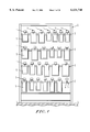
FIG. 1 illustrates a front view of a first embodiment of the present invention in a used state;
FIG. 2 illustrates a cross-sectional view of a main portion of the first embodiment of the present invention in a used state when viewed from a side;
FIG. 3 illustrates a side view of the first embodiment of the present invention in a used state;
FIG. 4 illustrates a plan view of the first embodiment of the present invention in a used state;
FIG. 5 illustrates a front view of the first embodiment of the present invention in a used state;
FIG. 6 illustrates an explanatory diagram for a state in which a manipulation bar is actuated in the first embodiment of the present invention;
FIG. 7 illustrates a side view of a second embodiment of the present invention in a used state;
FIG. 8 illustrates a plan view of the second embodiment of the present invention in a used state;
FIG. 9 illustrates a side view of a third embodiment of the present invention in a used state;
FIG. 10 illustrates a plan view of the third embodiment of the present invention in a used state;
FIG. 11 illustrates a side view of a fourth embodiment of the present invention in a used state;
FIG. 12 illustrates a plan view of the fourth embodiment of the present invention in a used state;
FIG. 13 illustrates a side view of a fifth embodiment of the present invention in a used state;
FIG. 14 illustrates a plan view of the fifth embodiment of the present invention in a used state;
FIG. 15 illustrates a side view of a sixth embodiment of the present invention in a used state;
FIG. 16 illustrates a plan view of the sixth embodiment of the present invention in a used state;
FIG. 17 illustrates a partially cross-sectioned side view of a seventh embodiment of the present invention in a used state;
FIG. 18 illustrates a plan view of the seventh embodiment of the present invention in a used state;
FIG. 19 illustrates a partially cross-sectioned side view of an eighth embodiment of the present invention in a used state;
FIG. 20 illustrates a plan view of the eighth embodiment of the present invention in a used state;
FIG. 21 illustrates a partially cross-sectioned side view of a ninth embodiment of the present invention in a used state;
FIG. 22 illustrates a plan view of the ninth embodiment of the present invention in a used state;
FIG. 23 illustrates a side view of a tenth embodiment of the present invention in a used state;
FIG. 24 illustrates a plan view of the tenth embodiment of the present invention in a used state;
FIG. 25 illustrates a side view of an eleventh embodiment of the present invention in a used state;
FIG. 26 illustrates a plan view of the eleventh embodiment of the present invention in a used state;
FIG. 27 illustrates a partial side view of a twelfth embodiment of the present invention in a used state;
FIG. 28 illustrates a plan view of the twelfth embodiment of the present invention in a used state;
FIG. 29 illustrates a side view of a thirteenth embodiment of the present invention in a used state;
FIG. 30 illustrates a plan view of the thirteenth embodiment of the present invention in a used state;
FIG. 31 illustrates a perspective view of a fourteenth embodiment of the present invention in a used state;
FIG. 32 illustrates a perspective view of a fifteenth embodiment of the present invention in a used state;
FIG. 33 illustrates a perspective view of a sixteenth embodiment of the present invention in a used state;
FIG. 34 illustrates a side view of FIG. 33 in a used state;
FIG. 35 illustrates a cross-sectional view taken along a line A--A in FIG. 33;
FIG. 36 illustrates an exploded view illustrating the structure of a seventeenth embodiment of the present invention;
FIGS. 37 and 38 illustrate partially cross-sectioned front views of an eighteenth embodiment of the present invention in a used state;
FIG. 39 illustrates a partially cut-away perspective view showing the eighteenth embodiment of the present invention; and
FIG. 40 illustrates a cross-sectional view for explaining a stopper means in the eighteenth embodiment of the present invention. In the drawings, reference numeral 1 designates an article display device of the present invention; 3 a bar member; 4 an engaging piece; 6 an article display bar; 7 a supporting bar; 9 a display plate; and 12 an urging body, respectively.
BEST MODE FOR CARRYING OUT THE INVENTION
The present invention will hereinafter be described in detail in connection with embodiments illustrated in the drawings.
In a first embodiment of the present invention in FIGS. 1-6, 1 designates an article display device of the present invention which is removably attached to a bar member 3 of an article display rack 2. This article display device 1 comprises a channel-like engaging piece 4 removably attached to the bar member 3; an article display bar 6 having the rear end secured to the engaging piece 4 by welding or the like and the front end inclined upwardly for suspending a large number of packaged articles 5; a supporting bar 7, positioned above the article display bar 6, having the rear end integrally formed with the engaging piece 4 or the rear end of the article display bar 6, in this embodiment, linked with the article display bar 6; a display plate 9 fitted on a front end portion of the supporting bar 7, on which a display card 8 can be securely adhered; an urging body 12, formed with an inserting hole 10 into which the supporting bar 7 is inserted, slidably suspended on the supporting bar 7 to have the ability of urging the articles 5 suspended on article display bar 6 , and having an elongated article display bar inserting hole 11; and means for sliding, a throughhole 13, formed through the display plate 9 and the urging body 12, in this embodiment, a manipulation bar 17 slidably extending through a throughhole 14 formed through the urging body 12, and having a stopping piece 15 formed at the rear end thereof for stopping the urging body 12 and a handle 16 formed at the front end thereof.
With the article display device 1 structured as mentioned above, the packaged articles 5 are loaded onto the article display bar 6 in a suspended state from the front end thereof and pushed toward the rear as illustrated in FIG. 3, whereby the urging body 12 is slid on the supporting bar 7 and positioned in the rear.
When the articles are sold so that no articles 5 are found at the forefront of the article display bar 6, the handle 16 of the manipulation bar 17 is held and pulled out, as illustrated in FIG. 6, to slide the urging body 12 to the front such that the articles 5 are extruded to the front.
When the articles 5 left in front are positioned in a front end portion of the article display bar 6, the manipulation bar 17 is pushed as indicated by a virtual line.
Next, different embodiments of the present invention illustrated in FIGS. 7-40 will be described. For describing these different embodiments of the present invention, the same constituents as those in the foregoing first embodiment of the present invention are designated the same reference numerals, and repetitive explanation is omitted.
A second embodiment of the present invention in FIGS. 7 and 8 differs from the foregoing first embodiment of the present invention mainly in that the rear end of the manipulation bar 17 is secured to the urging body 12, and an article display device 1A thus constructed also has similar meritorious effects to the foregoing first embodiment of the present invention.
A third embodiment of the present invention in FIGS. 9 and 10 differs from the foregoing second embodiment of the present invention mainly in that a supporting bar 7A composed of two parallelly arranged bar members 7a, 7a are used, and an article display device 1B thus constructed also has similar meritorious effects to the foregoing second embodiment of the present invention.
A fourth embodiment of the present invention in FIGS. 11 and 12 differs from the foregoing first embodiment mainly in that a wire is used to form a manipulation bar 17 having an urging body 12A formed in a rear end portion, and a sandwiching member 19 is formed for supporting a supporting bar 7, in a sandwiching form, to a supporting member 18 for slidably supporting the manipulation bar 17. An article display device 1C thus constructed also has similar meritorious effects to the foregoing second embodiment of the present invention.
A fifth embodiment of the present invention in FIGS. 13 and 14 differs from the foregoing first embodiment of the present invention mainly in that a resilient body 20, a tension spring in this embodiment, is interposed between the rear end of a manipulation bar 17 and the rear end of a supporting bar 7 such that the manipulation bar 17 may be always positioned in a retracted state. An article display device 1D thus constructed also has similar meritorious effects to the foregoing first embodiment of the present invention.
A sixth embodiment of the present invention in FIGS. 15 and 16 differs from the foregoing second embodiment mainly in that a manipulation bar 17 having an urging body 12A formed integrally therewith at the rear end may be always positioned in a retracted state with a tension spring 20. An article display device 1E thus constructed also has similar meritorious effects to the foregoing second embodiment of the present invention.
A seventh embodiment of the present invention in FIGS. 17 and 18 differs from the foregoing first embodiment of the present invention mainly in that an urging body 12 is automatically slid. In this embodiment, the urging body 12 is provided with a fixed load spring 21 for always moving the urging body 12 forwardly with a predetermined pushing pressure. An article display device 1F thus constructed also has similar meritorious effects to the foregoing first embodiment, and in addition, can automatically urge articles 5 forwardly.
An eighth embodiment of the present invention in FIGS. 19 and 20 differs from the foregoing seventh embodiment of the present invention mainly in that a display plate 9 is provided with a fixed load spring 21, and an article display device 1G thus constructed also has similar meritorious effects to the foregoing seventh embodiment of the present invention.
A ninth embodiment of the present invention in FIGS. 21 and 22 differs from the foregoing second embodiment of the present invention mainly in that an urging body 12 is attached to a position near the rear end of a movable display plate supporting bar 24, which has a display plate 9 at the front end thereof, slidably attached to a supporting bar 23. In this embodiment, a supporting bar 7B is composed of the cylindrical fixed supporting bar 23 having a guide groove 22 fixed to an engaging piece 4 and the movable display plate supporting bar 24, onto which the display plate 9 is fixedly fitted on a front end portion, slidably attached to the fixed supporting bar 23, and the urging body 12, which moves along the guide groove 22 of the fixed supporting bar 23, is secured to the rear end of the movable display plate supporting bar 24 of the supporting bar 7B. An article display device 1H thus constructed also has similar meritorious effects to the foregoing second embodiment of the present invention.
A tenth embodiment of the present invention in FIGS. 23 and 24 differs from the foregoing ninth embodiment of the present invention mainly in that the former employs a rod-like fixed supporting bar 23A, and also employs a supporting bar 7C which includes a cylindrical member serving as a movable display plate supporting bar 24A which is slidably attached to the fixed supporting bar 23A. An article display device 1I thus constructed also has similar meritorious effects to the foregoing ninth embodiment of the present invention.
An eleventh embodiment of the present invention in FIGS. 25 and 26 differs from the foregoing first embodiment of the present invention mainly in that a supporting bar 7 is inclined downwardly toward the front end such that an urging body 12 always slides to the front. An article display device 1J thus constructed also has similar meritorious effects to the foregoing first embodiment of the present invention.
A twelfth embodiment of the present invention in FIGS. 27 and 28 differs from the foregoing first embodiment of the present invention mainly in that an article display bar 6A having a non-circular cross-section, or a rectangular cross-section in this embodiment, and a supporting bar 7D having the rear end secured to an urging body 12B non-rotatably but slidably attached to the article display bar 6A are employed. An article display device 1K thus constructed also has similar meritorious effects to the foregoing first embodiment of the present invention, and can provide a simpler structure.
In this embodiment of the present invention, since the urging body 12B is only required to be non-rotatable about but slidable along the article display bar 6A, the article display bar 6A may be non-circular in cross-section and have a shaft which is elliptic, polygonal, or non-circular in cross section and formed with a guide piece, a guide groove, or the like.
A thirteenth embodiment of the present invention in FIGS. 29 and 30 differs from the foregoing first embodiment of the present invention mainly in that a slidable urging body 12 is attached to an article display bar 6, and a pressure applying mechanism 27 using a link 26 for always pushing the urging body 12 to the front with a spring 25 is attached to the urging body 12 and an engaging piece 4. An article display device 1L thus constructed also has similar meritorious effects to the foregoing first embodiment of the present invention, and in addition, can always push articles 5 to the front.
A fourteenth embodiment of the present invention in FIG. 31 differs from the foregoing first embodiment of the present invention mainly in that an urging body 12 automatically pushes articles 5 supported by an article display bar 6 with a tension force of a spring coil 28, and an article arrangement correcting member 29 is rotatably (omitted in the figures) disposed at the front end of a supporting bar 7 through a supporting block 30 for also preventing articles from dropping. The urging body 12 comprises guiding portions 121, 122 slidable on the supporting bar 7 and the article display bar 6, and is automatically pushed to the front by the action of the spring coil 28 having one end fixed in an upper portion of a pushing plate 123. The article arrangement correcting member 29 abuts to a portion positioned below an engaging position of an article 5 supported by the article display bar 6 and positioned at the forefront with the article display bar 6 (above the position of the center of gravity of the article) to correct the articles 5 supported by the article display bar 6 to be in a stationary state or in a substantially perpendicularly arranged posture. The article arrangement correcting member 29 is made of a transparent material such as acrylic resin or the like and molded into a vertically long rectangle. An article display device 1M thus constructed also has similar meritorious effects to the foregoing first embodiment of the present invention. Also, a combination of the urging body 12 and the article arrangement correcting member 29 provides either of heavy and light articles with more attractive appearance. Further, by forming an abutting end 291 at the lower end of the article arrangement correcting member 29 by bending the same toward the article 5, the article 5 is in contact with a smaller area of the article arrangement correcting member 29 so that damages to the article 5 due to friction with the article arrangement correcting member 29 can be reduced. When an article 5 is removed from the article display device 1M, the article 5 positioned at the head of the article display bar 6 is held by fingers and drawn out from the front end of the article display bar 6. Since this causes the article arrangement correcting member 29 to rotate (omitted in the figure), the extraction of an article can be facilitated. In this event, after the article 5 is extracted from the article display bar 6, the article arrangement correcting member 29 immediately returns to the original position, and the articles 5 supported by the article display bar 6 are arranged in a perpendicularly supported state by the forwardly urging action of the urging body 12.
A fifteenth embodiment of the present invention in FIG. 32 differs from the foregoing fourteenth embodiment of the present invention in that an urging body 12 is guided and slid along a supporting bar 7 by a guide roller 124. An article display device 1N thus constructed also has similar meritorious effects to the foregoing fourteenth embodiment of the present invention.
A sixteenth embodiment of the present invention in FIGS. 33-35 differs from the foregoing fifteenth embodiment of the present invention in that a cover case 40 having a guide groove 126, along which an urging body 12 slides, is formed to cover a supporting bar 7. An article display device 1P thus constructed, in addition to having similar meritorious effects to the foregoing fourteenth embodiment of the present invention, serves as an attractive display device since the cover case 40 covers a spring coil, a leaf spring, and so on.
A seventeenth embodiment of the present invention in FIG. 36 differs from the sixteenth embodiment in a rotation supporting mechanism for the article arrangement correcting member 29. More specifically, in place of the stopper member and a spring (omitted in the figure) in FIG. 33, a pair of engaging portions 36a is formed integrally with a supporting block 36 constituting a rotation supporting mechanism 31 substantially in a central portion of the top surface of the supporting block 36, and the supporting block 36 is attached to the article arrangement correcting member 29 through a torsion spring 38. An article display device 1Q thus constructed also has similar meritorious effects to the foregoing fourteenth embodiment of the present invention. Moreover, in FIG. 36, when articles 5 are supplemented to or fully extracted from the article display device 1Q, the article arrangement correcting member 29 is rotated upwardly and slid toward the supporting block 36, causing the engaging portions 36a of the supporting block 36 to engage with an engaging portion 36b of a display plate 9, so that the article arrangement correcting member 29 is held in a horizontal state. For this reason, the structure of the rotation supporting mechanism 31 can be made simpler, so that a reduced cost can be attained for the article display device. In addition, the supplement and extraction of articles are facilitated.
An eighteenth embodiment of the present invention in FIGS. 37-40 differs from the seventeenth embodiment in that a means for stopping or releasing the stoppage of an urging body 12 in the rear is provided. More specifically, a stopping means 212 and a stoppage releasing means 211 are attached on the top of a cover case 40 in FIG. 37. The stoppage is achieved by engaging a protrusive stopper 212a fixed to the cover case 40 with a stopper protrusion 178 positioned in a rear portion of the urging body 12.
The stoppage releasing means 211, which is composed of a stoppage releasing protrusion 211a, a stoppage releasing lever 211b and a link 211c for linking them, is attached on a supporting bar for movement in the longitudinal direction. For releasing a stopped state of the urging body 12 in a state of FIG. 40(b), the stoppage releasing lever 211b may be held by fingers at the front end thereof and pulled to the front. Specifically, this causes the stoppage releasing protrusion 211a to push up the stopper protrusion 178 upwardly to release the stopped state (FIG. 40(a)).
An article display device 1R thus constructed, in addition to having similar meritorious effects to the foregoing seventeenth embodiment of the present invention, provides a higher operability since the urging body 12 is not interfered when articles are displayed or removed using the article display device 1.
While the foregoing respective embodiments of the present invention have been described in connection with the engaging piece 4 fixed to the article display bar 6 or 6A by welding or the like, the present invention is not limited to this, but may employ integrally formed engaging piece 4 and article display bar 6 or 6A.
Also, while the supporting bar 7 having the display plate 9 attached at the front end thereof has been described, the present invention is not limited to this, and the supporting bar 7 may be used without attaching the display plate 9 at the front end thereof.

Claims (1)

What is claimed is:
1. An article display device configured to be attached to an article display rack having a bar member, comprising:
an engaging piece configured to be attached to the bar member of the article display rack;
an article display bar on which at least one article may be supported and which has a front end and a rear end which is connected to the engaging piece;
a supporting bar extending along and positioned above the article display bar, the supporting bar being connected to one of the engaging piece and the rear end of the article display bar;
an urging body which is slidably supported by the supporting bar, whereby forward movement of the urging body will cause the at least one article supported by the article display bar to be moved along the article display bar toward the front end of the article display bar;
a manipulation bar having a rear portion attached to the urging body and extending along the supporting bar; and
a resilient body, connected to the manipulation bar, configured and arranged to urge the manipulation bar toward the rear end of the article display bar.
US09/068,105 1995-11-13 1996-11-01 Article display device Expired - Lifetime US6131748A (en)

Applications Claiming Priority (5)

Application Number Priority Date Filing Date Title
JP7-318604 1995-11-13
JP31860495A JP3166821B2 (en) 1995-11-13 1995-11-13 Product display
JP8-051648 1996-03-08
JP5164896A JPH09238791A (en) 1996-03-08 1996-03-08 Merchandise display instrument
PCT/JP1996/003224 WO1997017872A1 (en) 1995-11-13 1996-11-01 Showcase device

Publications (1)

Publication Number Publication Date
US6131748A true US6131748A (en) 2000-10-17

Family

ID=26392201

Family Applications (1)

Application Number Title Priority Date Filing Date
US09/068,105 Expired - Lifetime US6131748A (en) 1995-11-13 1996-11-01 Article display device

Country Status (5)

Country Link
US (1) US6131748A (en)
EP (1) EP0868871B1 (en)
AT (1) ATE206595T1 (en)
DE (1) DE69615863T2 (en)
WO (1) WO1997017872A1 (en)

Cited By (55)

* Cited by examiner, † Cited by third party
Publication number Priority date Publication date Assignee Title
US6445373B1 (en) * 1998-09-10 2002-09-03 Sony Corporation Display apparatus
US6446819B1 (en) * 1997-04-09 2002-09-10 Magla Products, L.L.C. Device for loading merchandise onto display pegs
US20020166824A1 (en) * 2001-04-03 2002-11-14 Magla Products, L.L.C. Method for loading merchandise onto pegboard display
US20020166213A1 (en) * 1997-04-09 2002-11-14 Magla Products, L.L.C. Device for loading merchandise onto pegboard display
US20030188470A1 (en) * 2002-04-06 2003-10-09 Valiulis Carl A. Aligning product packages displayed on a scanning hook
US6719151B2 (en) * 2001-05-16 2004-04-13 James Garth Close System and method for product display, arrangement and rotation
US20040084386A1 (en) * 1999-11-03 2004-05-06 David Huehner Security device for preventing rapid removal of merchandise
US20040182975A1 (en) * 2003-03-17 2004-09-23 Southern Imperial, Inc. Display hook and assembly having reduced drag
US20050029205A1 (en) * 2003-08-06 2005-02-10 Mansfield Eric H. Merchandise display hook
US20050040122A1 (en) * 2002-02-21 2005-02-24 Hl Display Ab Arrangement for product display prongs
US20050061756A1 (en) * 2003-08-01 2005-03-24 Henry Mattesky Peg hook loader and method for its use
US20050077257A1 (en) * 2002-02-21 2005-04-14 Bengt Ahlund Arrangement for merchandise display prongs
US20050189369A1 (en) * 2003-10-17 2005-09-01 Kirk Vlastakis Theft deterrent system
WO2005000075A3 (en) * 2003-06-13 2005-09-15 Dci Marketing Inc Merchandising system
US20050236544A1 (en) * 2002-07-17 2005-10-27 Device Works Company Cable organization and hardware shelving system
US20050279894A1 (en) * 2003-11-12 2005-12-22 Sedon Nicholas M Locking base for display hook
US20060076301A1 (en) * 2004-10-07 2006-04-13 Fasteners For Retail, Inc. Package conveyor
US20060157431A1 (en) * 2005-01-14 2006-07-20 Alpha Security Products, Inc. Display rod lock mechanism
US20070102379A1 (en) * 2005-11-10 2007-05-10 Sargento Foods, Inc. Removable product support bar display apparatus and method
US7219806B1 (en) * 2004-03-15 2007-05-22 In-Store Systems, Llc Product display apparatus
US20070170127A1 (en) * 2003-05-22 2007-07-26 Dci Marketing, Inc., A Wisconsin Corporation Merchandising system
US20070283615A1 (en) * 2006-06-12 2007-12-13 Rock-Tenn Shared Services, Llc Theft deterrent system hook
US20080302741A1 (en) * 2007-06-06 2008-12-11 Opher Pail Product display system, method and apparatus
US20090184130A1 (en) * 2003-10-17 2009-07-23 Miller Roger K Secure merchandising system
US7641072B1 (en) 2003-10-17 2010-01-05 Rock-Tenn Shared Services, Llc Theft deterrent system
US7854333B2 (en) 2008-05-07 2010-12-21 Dci Marketing, Inc. Rear loading gate for merchandising system
US20110215060A1 (en) * 2010-03-04 2011-09-08 Southern Imperial, Inc. Alarm Sounding Retail Display System
US20110215061A1 (en) * 2010-03-05 2011-09-08 Southern Imperial, Inc. Retail Merchandise Hook
US20110218889A1 (en) * 2010-03-05 2011-09-08 Southern Imperial, Inc. Retail Display System With Integrated Security and Inventory Management
US8098054B2 (en) 2007-10-10 2012-01-17 John Alexander Verschuur Optimal load controller method and device
US8190289B2 (en) 2003-10-17 2012-05-29 Rock-Tenn Shared Services, Llc Dispensing and display system
WO2012152954A1 (en) * 2011-05-09 2012-11-15 Roman Moreno Sarmiento Device for hanging up a display panel
US8353425B2 (en) 2005-04-25 2013-01-15 Rock-Tenn Shared Services, Llc Time delay product pushing system
US8485391B2 (en) 2003-10-17 2013-07-16 Rock-Tenn Shared Services, Llc Theft deterrent system
US8646650B2 (en) 2010-05-19 2014-02-11 Rock-Tenn Shared Services, Llc Product dispensing system
US8739980B2 (en) * 2011-07-08 2014-06-03 Southern Imperial, Inc. Pusher hook with limited stroke
US8910827B2 (en) 2011-05-10 2014-12-16 Rock-Tenn Shared Services, Llc Secure merchandising display with tunnel feature
US9119488B2 (en) 2009-09-25 2015-09-01 Rock-Tenn Shared Services, Llc Secure merchandising display with blocker mechanisms
US9129494B2 (en) 2012-12-13 2015-09-08 Southern Imperial, Inc. Alarming pusher system
US9320367B2 (en) 2014-02-26 2016-04-26 Southern Imperial, Inc. Snap-in pusher
US9339123B1 (en) * 2013-12-12 2016-05-17 Performance Display Group, Inc. Merchandise display
US20160157636A1 (en) * 2013-09-06 2016-06-09 T.M. Shea Products, Inc. Signage systems and merchandising display assemblies
US20170007043A1 (en) * 2014-06-10 2017-01-12 Winston Products Merchandizing system for displaying cleaning devices
USD801734S1 (en) 2014-12-01 2017-11-07 Retail Space Solutions Llc Shelf management parts
US9820587B1 (en) * 2016-07-15 2017-11-21 Guangzhou Hybon Electronic Technology Co., Limited Merchandise security hook
US10016070B1 (en) * 2015-09-11 2018-07-10 Henschel-Steinau, Inc. Pull-slide system and method for suspended merchandise items
US10154739B2 (en) 2013-12-02 2018-12-18 Retail Space Solutions Llc Universal merchandiser and methods relating to same
US20190029444A1 (en) * 2017-07-26 2019-01-31 DaVinci Industries Product display belt and assembly
US20190164378A1 (en) * 2018-07-04 2019-05-30 Ti Chin CHANG hanging rod control device for display rack
US10926152B2 (en) * 2019-03-12 2021-02-23 Mak Pickleball, Llc Storage rack and conveyor for sports equipment
US10959540B2 (en) 2016-12-05 2021-03-30 Retail Space Solutions Llc Shelf management system, components thereof, and related methods
US11045017B2 (en) 2017-04-27 2021-06-29 Retail Space Solutions Llc Shelf-mounted tray and methods relating to same
US11178980B2 (en) * 2017-05-19 2021-11-23 Ivan Pongrac Retail device
TWI767685B (en) * 2021-05-04 2022-06-11 台灣河淳股份有限公司 Advancing display attachment for peg hook
US11363894B2 (en) 2019-04-05 2022-06-21 Fasteners For Retail, Inc. Anti-theft pusher with incremental distance detection

Families Citing this family (6)

* Cited by examiner, † Cited by third party
Publication number Priority date Publication date Assignee Title
SE519477C2 (en) * 2001-09-20 2003-03-04 Hl Display Ab Device for product exposure spear
DE10211789A1 (en) * 2002-03-16 2003-10-09 Geha German Hardcopy Ag Vending display stand has array of marked storage sites with identity markings to store sorted items
GB0401176D0 (en) * 2004-01-19 2004-02-25 Macaulay James L Helix security dispenser
US7566037B2 (en) * 2007-02-26 2009-07-28 Vogler Michael N Pusher accessory for product hanging hooks
NL2008655C2 (en) * 2012-04-18 2013-10-21 Bernardus Anthonius Soet A DRAWING DEVICE FOR MERCHANTS AND RELATED DEPARTMENT DEVICE.
US20160367049A1 (en) * 2015-06-22 2016-12-22 Colgate-Palmolive Company Extendable display hanger

Citations (5)

* Cited by examiner, † Cited by third party
Publication number Priority date Publication date Assignee Title
US1702987A (en) * 1928-04-17 1929-02-19 Gordon C Wilson Tray
US4475658A (en) * 1979-03-14 1984-10-09 Roberts Display Corporation Spring-loaded merchandising device
US4869376A (en) * 1988-04-25 1989-09-26 Southern Imperial, Inc. Inventory control device for display hook
US5325616A (en) * 1993-03-18 1994-07-05 Southern Imperial, Inc. Label holder for display hangers
US5485930A (en) * 1994-07-14 1996-01-23 Hmg Worldwide Corporation Anti-theft display hook

Family Cites Families (4)

* Cited by examiner, † Cited by third party
Publication number Priority date Publication date Assignee Title
JPS564385Y2 (en) 1979-02-21 1981-01-30
JPS5831869U (en) 1981-08-27 1983-03-02 株式会社岡村製作所 Product display device
JPH0438781Y2 (en) * 1989-07-28 1992-09-10
JP2829831B2 (en) * 1994-11-02 1998-12-02 サンコースプリング株式会社 Product hanging display equipment

Patent Citations (5)

* Cited by examiner, † Cited by third party
Publication number Priority date Publication date Assignee Title
US1702987A (en) * 1928-04-17 1929-02-19 Gordon C Wilson Tray
US4475658A (en) * 1979-03-14 1984-10-09 Roberts Display Corporation Spring-loaded merchandising device
US4869376A (en) * 1988-04-25 1989-09-26 Southern Imperial, Inc. Inventory control device for display hook
US5325616A (en) * 1993-03-18 1994-07-05 Southern Imperial, Inc. Label holder for display hangers
US5485930A (en) * 1994-07-14 1996-01-23 Hmg Worldwide Corporation Anti-theft display hook

Cited By (84)

* Cited by examiner, † Cited by third party
Publication number Priority date Publication date Assignee Title
US20050022345A9 (en) * 1997-04-09 2005-02-03 Magla Products, L.L.C. Device for loading merchandise onto pegboard display
US6446819B1 (en) * 1997-04-09 2002-09-10 Magla Products, L.L.C. Device for loading merchandise onto display pegs
US20020166213A1 (en) * 1997-04-09 2002-11-14 Magla Products, L.L.C. Device for loading merchandise onto pegboard display
US7028376B2 (en) 1997-04-09 2006-04-18 Magla Products, L.L.C. Device for loading merchandise onto pegboard display
US6445373B1 (en) * 1998-09-10 2002-09-03 Sony Corporation Display apparatus
US7007810B2 (en) * 1999-11-03 2006-03-07 Alpha Security Products, Inc. Security device for preventing rapid removal of merchandise
US20040084386A1 (en) * 1999-11-03 2004-05-06 David Huehner Security device for preventing rapid removal of merchandise
US20020166824A1 (en) * 2001-04-03 2002-11-14 Magla Products, L.L.C. Method for loading merchandise onto pegboard display
US6719151B2 (en) * 2001-05-16 2004-04-13 James Garth Close System and method for product display, arrangement and rotation
US20050040122A1 (en) * 2002-02-21 2005-02-24 Hl Display Ab Arrangement for product display prongs
US20050077257A1 (en) * 2002-02-21 2005-04-14 Bengt Ahlund Arrangement for merchandise display prongs
US20030188470A1 (en) * 2002-04-06 2003-10-09 Valiulis Carl A. Aligning product packages displayed on a scanning hook
US20050236544A1 (en) * 2002-07-17 2005-10-27 Device Works Company Cable organization and hardware shelving system
US20040182975A1 (en) * 2003-03-17 2004-09-23 Southern Imperial, Inc. Display hook and assembly having reduced drag
WO2004083051A3 (en) * 2003-03-17 2005-05-06 Southern Imperial Inc Retail display support having reduced drag and method
WO2004083051A2 (en) * 2003-03-17 2004-09-30 Southern Imperial, Inc. Retail display support having reduced drag and method
US7278617B2 (en) * 2003-03-17 2007-10-09 Southern Imperial, Inc. Display hook and assembly having reduced drag
US20040182976A1 (en) * 2003-03-17 2004-09-23 Southern Imperial, Inc. Retail display support having reduced drag and method
US7681744B2 (en) 2003-05-22 2010-03-23 Dci Marketing, Inc. Merchandising system
US20070170127A1 (en) * 2003-05-22 2007-07-26 Dci Marketing, Inc., A Wisconsin Corporation Merchandising system
WO2005000075A3 (en) * 2003-06-13 2005-09-15 Dci Marketing Inc Merchandising system
US20050061756A1 (en) * 2003-08-01 2005-03-24 Henry Mattesky Peg hook loader and method for its use
US20050029205A1 (en) * 2003-08-06 2005-02-10 Mansfield Eric H. Merchandise display hook
US7178678B2 (en) 2003-08-06 2007-02-20 Alpha Security Products, Inc. Merchandise display hook
US7708153B2 (en) 2003-08-06 2010-05-04 Invue Security Products Inc. Merchandise display hook
US20070119797A1 (en) * 2003-08-06 2007-05-31 Alpha Security Products, Inc. Merchandise display hook
US20050189369A1 (en) * 2003-10-17 2005-09-01 Kirk Vlastakis Theft deterrent system
US8215520B2 (en) 2003-10-17 2012-07-10 Rock-Tenn Shared Services, Llc Secure merchandising system
US8190289B2 (en) 2003-10-17 2012-05-29 Rock-Tenn Shared Services, Llc Dispensing and display system
US9483896B2 (en) 2003-10-17 2016-11-01 Westrock Shared Services, Llc Dispensing and display system
US8386075B2 (en) 2003-10-17 2013-02-26 Rock-Tenn Shared Services, Llc Dispensing and display system
US8485391B2 (en) 2003-10-17 2013-07-16 Rock-Tenn Shared Services, Llc Theft deterrent system
US9052994B2 (en) 2003-10-17 2015-06-09 Rock-Tenn Shared Services, Llc Dispensing and display system
US20090184130A1 (en) * 2003-10-17 2009-07-23 Miller Roger K Secure merchandising system
US7641072B1 (en) 2003-10-17 2010-01-05 Rock-Tenn Shared Services, Llc Theft deterrent system
US20050279894A1 (en) * 2003-11-12 2005-12-22 Sedon Nicholas M Locking base for display hook
US7219806B1 (en) * 2004-03-15 2007-05-22 In-Store Systems, Llc Product display apparatus
US20060076301A1 (en) * 2004-10-07 2006-04-13 Fasteners For Retail, Inc. Package conveyor
US20060157431A1 (en) * 2005-01-14 2006-07-20 Alpha Security Products, Inc. Display rod lock mechanism
US8353425B2 (en) 2005-04-25 2013-01-15 Rock-Tenn Shared Services, Llc Time delay product pushing system
US20070102379A1 (en) * 2005-11-10 2007-05-10 Sargento Foods, Inc. Removable product support bar display apparatus and method
US7533784B2 (en) * 2006-06-12 2009-05-19 Rock-Tenn Shared Services, Llc Theft deterrent system hook
US20070283615A1 (en) * 2006-06-12 2007-12-13 Rock-Tenn Shared Services, Llc Theft deterrent system hook
US7905364B2 (en) * 2007-06-06 2011-03-15 Opher Pail Product display system, method and apparatus
US20080302741A1 (en) * 2007-06-06 2008-12-11 Opher Pail Product display system, method and apparatus
US8098054B2 (en) 2007-10-10 2012-01-17 John Alexander Verschuur Optimal load controller method and device
US7854333B2 (en) 2008-05-07 2010-12-21 Dci Marketing, Inc. Rear loading gate for merchandising system
US9119488B2 (en) 2009-09-25 2015-09-01 Rock-Tenn Shared Services, Llc Secure merchandising display with blocker mechanisms
US8443988B2 (en) 2010-03-04 2013-05-21 Southern Imperial, Inc. Alarm sounding retail display system
US20110215060A1 (en) * 2010-03-04 2011-09-08 Southern Imperial, Inc. Alarm Sounding Retail Display System
US20110218889A1 (en) * 2010-03-05 2011-09-08 Southern Imperial, Inc. Retail Display System With Integrated Security and Inventory Management
US8439208B2 (en) 2010-03-05 2013-05-14 Southern Imperial, Inc. Retail merchandise hook
US20110215061A1 (en) * 2010-03-05 2011-09-08 Southern Imperial, Inc. Retail Merchandise Hook
US8240486B2 (en) * 2010-03-05 2012-08-14 Southern Imperial, Inc. Retail merchandise hook
US8646650B2 (en) 2010-05-19 2014-02-11 Rock-Tenn Shared Services, Llc Product dispensing system
WO2012152954A1 (en) * 2011-05-09 2012-11-15 Roman Moreno Sarmiento Device for hanging up a display panel
US8910827B2 (en) 2011-05-10 2014-12-16 Rock-Tenn Shared Services, Llc Secure merchandising display with tunnel feature
US9603467B2 (en) 2011-05-10 2017-03-28 Westrock Shared Services, Llc Secure merchandising display with tunnel feature
US8739980B2 (en) * 2011-07-08 2014-06-03 Southern Imperial, Inc. Pusher hook with limited stroke
US9129494B2 (en) 2012-12-13 2015-09-08 Southern Imperial, Inc. Alarming pusher system
US9867483B2 (en) * 2013-09-06 2018-01-16 T.M. Shea Products, Inc. Signage systems and merchandising display assemblies
US20160157636A1 (en) * 2013-09-06 2016-06-09 T.M. Shea Products, Inc. Signage systems and merchandising display assemblies
US10154739B2 (en) 2013-12-02 2018-12-18 Retail Space Solutions Llc Universal merchandiser and methods relating to same
US9339123B1 (en) * 2013-12-12 2016-05-17 Performance Display Group, Inc. Merchandise display
US9320367B2 (en) 2014-02-26 2016-04-26 Southern Imperial, Inc. Snap-in pusher
US20170007043A1 (en) * 2014-06-10 2017-01-12 Winston Products Merchandizing system for displaying cleaning devices
US10052752B2 (en) * 2014-06-10 2018-08-21 Winston Products, Llc Merchandizing system for displaying cleaning devices
USD801734S1 (en) 2014-12-01 2017-11-07 Retail Space Solutions Llc Shelf management parts
USD874197S1 (en) 2014-12-01 2020-02-04 Retail Space Solutions Llc Shelf management dividers
US10016070B1 (en) * 2015-09-11 2018-07-10 Henschel-Steinau, Inc. Pull-slide system and method for suspended merchandise items
US9820587B1 (en) * 2016-07-15 2017-11-21 Guangzhou Hybon Electronic Technology Co., Limited Merchandise security hook
US10959540B2 (en) 2016-12-05 2021-03-30 Retail Space Solutions Llc Shelf management system, components thereof, and related methods
US11045017B2 (en) 2017-04-27 2021-06-29 Retail Space Solutions Llc Shelf-mounted tray and methods relating to same
US11178980B2 (en) * 2017-05-19 2021-11-23 Ivan Pongrac Retail device
US10426278B2 (en) * 2017-07-26 2019-10-01 DaVinci Industries Product display belt and assembly
US10736442B2 (en) * 2017-07-26 2020-08-11 DaVinci Industries Product display belt and assembly
US20190374048A1 (en) * 2017-07-26 2019-12-12 DaVinci Industries Product display belt and assembly
US20190029444A1 (en) * 2017-07-26 2019-01-31 DaVinci Industries Product display belt and assembly
US10755516B2 (en) * 2018-07-04 2020-08-25 Brighton-Best International (Taiwan) Inc. Hanging rod control device for display rack
US20190164378A1 (en) * 2018-07-04 2019-05-30 Ti Chin CHANG hanging rod control device for display rack
US10926152B2 (en) * 2019-03-12 2021-02-23 Mak Pickleball, Llc Storage rack and conveyor for sports equipment
US11363894B2 (en) 2019-04-05 2022-06-21 Fasteners For Retail, Inc. Anti-theft pusher with incremental distance detection
US11707141B2 (en) 2019-04-05 2023-07-25 Fasteners For Retail, Inc. Anti-theft pusher with incremental distance detection
TWI767685B (en) * 2021-05-04 2022-06-11 台灣河淳股份有限公司 Advancing display attachment for peg hook

Also Published As

Publication number Publication date
EP0868871A1 (en) 1998-10-07
DE69615863D1 (en) 2001-11-15
EP0868871B1 (en) 2001-10-10
DE69615863T2 (en) 2002-05-29
WO1997017872A1 (en) 1997-05-22
ATE206595T1 (en) 2001-10-15
EP0868871A4 (en) 1999-01-20

Similar Documents

Publication Publication Date Title
US6131748A (en) Article display device
US4042096A (en) Shelf aid
US5613621A (en) Inventory control shelf aid dispensing device
US5586687A (en) Gravity feed bottle dispensing device having a track-blocking gate mechanism
US4706821A (en) Merchandise display and dispensing device
US20030057167A1 (en) Merchandising system
US20030141265A1 (en) Merchandise display device
EP1312285A1 (en) Cassette for merchandise
EP1462035B1 (en) Goods display apparatus
US4416407A (en) Dispensing of fasteners with a pivoted and disengageable feed mechanism
GB9412349D0 (en) Device to close a side dispensing orifice by axial sliding with push button element
ES1051662U (en) Fly screen with a quick-release mechanism for hooking and unhooking the handle
US20050077257A1 (en) Arrangement for merchandise display prongs
EP1241965A1 (en) Display assembly
DE102004042433A1 (en) Magnifying glass for attachment to supermarket trolley helps shoppers to read labels on goods and is attached to pocket on side of trolley by cord and has protective housing for glass
US5368189A (en) Vending machine for newspapers and like articles
US4718590A (en) Fastener dispensing devices
EP1366994A1 (en) Locking element attaching device
JP2567319Y2 (en) Product display stand
JP3894516B2 (en) Product display
JP3166821B2 (en) Product display
JP3471554B2 (en) Vending machine product storage device
JPH10247272A (en) Automatic vending machine
JP3894515B2 (en) Product display
JPH08322689A (en) Flat article exhibiting casing

Legal Events

Date Code Title Description
AS Assignment

Owner name: KAWASAKI, JUNZABURO, JAPAN

Free format text: ASSIGNMENT OF ASSIGNORS INTEREST;ASSIGNORS:KAWASAKI, JUNZABURO;KAWAMURA, HIDEAKI;ENDO, AKIHIKO;REEL/FRAME:009608/0485

Effective date: 19980424

Owner name: KAWAJUN CO., LTD., JAPAN

Free format text: ASSIGNMENT OF ASSIGNORS INTEREST;ASSIGNORS:KAWASAKI, JUNZABURO;KAWAMURA, HIDEAKI;ENDO, AKIHIKO;REEL/FRAME:009608/0485

Effective date: 19980424

STCF Information on status: patent grant

Free format text: PATENTED CASE

FPAY Fee payment

Year of fee payment: 4

FPAY Fee payment

Year of fee payment: 8

FPAY Fee payment

Year of fee payment: 12