US6123409A - Inkjet printhead with capillary channels for receiving wiped ink and residue - Google Patents
Inkjet printhead with capillary channels for receiving wiped ink and residue Download PDFInfo
- Publication number
- US6123409A US6123409A US09/487,331 US48733100A US6123409A US 6123409 A US6123409 A US 6123409A US 48733100 A US48733100 A US 48733100A US 6123409 A US6123409 A US 6123409A
- Authority
- US
- United States
- Prior art keywords
- orifice plate
- fins
- printhead
- capillary
- inkjet printhead
- Prior art date
- Legal status (The legal status is an assumption and is not a legal conclusion. Google has not performed a legal analysis and makes no representation as to the accuracy of the status listed.)
- Expired - Lifetime
Links
Images
Classifications
-
- B—PERFORMING OPERATIONS; TRANSPORTING
- B41—PRINTING; LINING MACHINES; TYPEWRITERS; STAMPS
- B41J—TYPEWRITERS; SELECTIVE PRINTING MECHANISMS, i.e. MECHANISMS PRINTING OTHERWISE THAN FROM A FORME; CORRECTION OF TYPOGRAPHICAL ERRORS
- B41J2/00—Typewriters or selective printing mechanisms characterised by the printing or marking process for which they are designed
- B41J2/005—Typewriters or selective printing mechanisms characterised by the printing or marking process for which they are designed characterised by bringing liquid or particles selectively into contact with a printing material
- B41J2/01—Ink jet
- B41J2/135—Nozzles
- B41J2/165—Preventing or detecting of nozzle clogging, e.g. cleaning, capping or moistening for nozzles
- B41J2/16517—Cleaning of print head nozzles
- B41J2/16535—Cleaning of print head nozzles using wiping constructions
- B41J2/16538—Cleaning of print head nozzles using wiping constructions with brushes or wiper blades perpendicular to the nozzle plate
Definitions
- the present invention relates generally to inkjet printers and, more particularly, to the cleaning of printhead wipers which are used to clean the orifices of an orifice plate of a replaceable inkjet printhead cartridge.
- Some systems use rotary wipers at the service station for swiping the printhead in a direction orthogonal to the direction of carriage movement.
- Other systems employ statically mounted wipers which are engaged by the printhead orifice plates during the linear movement of the printhead carriage.
- One system for periodically cleaning the printhead wipers is shown in U.S. Pat. No. 5,815,176 issued Sep. 29, 1998 to Rotering and owned by the assignee of the present invention.
- Other systems for cleaning the inkjet wipers are disclosed in U.S. Pat. No. 5,182,582 issued Jan. 26, 1993 to Okamura and U.S. Pat. No. 5,581,282 issued Dec.
- the present invention accordingly provides an inkjet printhead comprising a housing, electrical conductors including contact pads on a front side of said housing and an inkjet orifice plate on said front side of said housing in an area to be swept by a resilient printhead wiper on a printer as said printhead is moved relative to said wiper, said housing further including at least one residue collector alongside said orifice plate in said area, said collector comprising a plurality of spaced fins defining first capillary channels between said fins for drawing wiped ink and residue away from said orifice plate by capillary action.
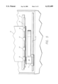
- FIG. 2 is a front elevation view of a prior art printhead.
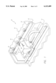
- FIG. 3 is a front elevation view of a printhead with capillary ink and residue collectors thereon according to the invention.
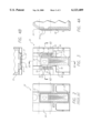
- FIG. 4A is a vertical cross-section of the printhead taken at lines 4A--4A of FIG. 3.
- FIG. 4B is a horizontal cross-section of the printhead taken at lines 4B--4B of FIG. 3.
- FIG. 5 is a top plan view of the printhead of FIG. 3 in a printer showing wiping of the printhead.
- a plurality of electrical leads through which electrical charge is conducted to fire the individual inozzles extend downwardly from the orifice plate and each terminating in exteriorly exposed contact pads 23 on the front generally planar front surface 25 of the orifice plate 24 from which ink droplets are ejected.
- a generally horizontally extending strip or barrier defined between the phantom lines shown on FIGS. 2 and 3 comprises an area 26 which is swept by a flexible wiper 42 mounted at a suitable location on the printer (FIG. 5) as the printhead moves into and out of a service station shown at the left side of the printer. Ink and residue swept from the printhead shown in FIG. 2 is received in recesses on the front of the cartridge alongside the orifice plate from which the ink and residue gravitates downwardly.
- the fins 32 are straight parallel fins which extend angularly downwardly away from the orifice plate 24, the fins being equally spaced to define capillary channels of equal width which may be about 0.02". As shown, the fins are also of the same length and height so that the capillary channels 33 are of equal volume but persons skilled in the art will understand that the capillary width and volumes of the channels may be varied if desired for special purposes. Also, the fins need not necessarily be straight or even parallel provided that the width of the capillary channels between the fins is sufficient to draw ink removed by the as wiper 42 away from the orifice plate 24.
- the edge 27 of the orifice plate is laterally spaced from ends 34 of the fins 32 a distance which defines a second capillary channel 36 which extends vertically between the edge 27 of the orifice plate 24 and the ends 34 of the fins.
- the capillary channel 36 is slightly wider, e.g., about 0.03" than the first capillary channels 33 so that the capillary action of the first channels 33 tends to pull ink and residue out of and away from the second capillary channel 36.
- At the lower end of the second capillary channel 36 is a widened area providing a capillary break 40 above the electrical contact pads 24.
- the capillary break 40 ensures that ink and residue do not drain downwardly through the channel 36 past the break 40 to thus come into contact with the electrical contact pads 23 which should remain clean.
- the printhead housing 22 is constructed such that the orifice plate 24 is mounted in a vertically extending recess bounded by forwardly extending ends 37 of the fins 32 such that the substantially flat front surface 25 of the orifice plate 28 is recessed away from the fin ends 37. This prevents the wiper 42 from contacting the side edges 27, 28 of the orifice plate which may be relatively sharp and thus cause undue wear of the resilient wiper 42.
- a second residue collector 50 is also preferably provided on the front of the printhead as seen in FIG. 3 and, as shown, is constructed identically with the residue collector 30.
- the fins 52 of a second residue collector 50 are also angled downwardly and away from the adjacent edge 28 of the orifice plate 24 and provide capillary channels 53 between the fins 52 for attracting and retaining ink and residue swept by the wiper blade 42 from the orifice plate 24.
- a vertically extending channel 56 of width greater than the width of the capillary channels 53 is also provided and the front edges 57 of the fins 52 occupy the same plane as the front edges 37 of the fins 32 of the first residue collector 30 so that neither side edge 27 or 28 of the orifice plate 24 will come into contact with the wiper blade 42.
- the capillary channels 33, 53 between the fins of each residue collector and the capillary channels 36, 56 between the residue collectors and the orifice plate cooperate with each other to ensure that ink and residue is directed to appropriate storage areas and to ensure that ink and residue is not directed towards undesired areas such as the electrical contact pads 23.
- the capillary breaks 40, 60 as shown in the form of 90° outside corners, effectively eliminate the capillary forces at the desired locations by providing a very large contact wetting angle which assures retention of the liquid ink and any residue or contaminants therein in the capillary channels. It should also be noted that accumulating fibrous paper residue and dust which is retained in the capillary channels 33, 53 significantly increases the capillary force in the capillary channels as compared with the capillary force in the relatively clean channels 33, 53 at the outset.
Abstract
Description
Claims (17)
Priority Applications (1)
| Application Number | Priority Date | Filing Date | Title |
|---|---|---|---|
| US09/487,331 US6123409A (en) | 2000-01-19 | 2000-01-19 | Inkjet printhead with capillary channels for receiving wiped ink and residue |
Applications Claiming Priority (1)
| Application Number | Priority Date | Filing Date | Title |
|---|---|---|---|
| US09/487,331 US6123409A (en) | 2000-01-19 | 2000-01-19 | Inkjet printhead with capillary channels for receiving wiped ink and residue |
Publications (1)
| Publication Number | Publication Date |
|---|---|
| US6123409A true US6123409A (en) | 2000-09-26 |
Family
ID=23935300
Family Applications (1)
| Application Number | Title | Priority Date | Filing Date |
|---|---|---|---|
| US09/487,331 Expired - Lifetime US6123409A (en) | 2000-01-19 | 2000-01-19 | Inkjet printhead with capillary channels for receiving wiped ink and residue |
Country Status (1)
| Country | Link |
|---|---|
| US (1) | US6123409A (en) |
Cited By (13)
| Publication number | Priority date | Publication date | Assignee | Title |
|---|---|---|---|---|
| US6655792B2 (en) | 2001-07-31 | 2003-12-02 | Hewlett-Packard Development Company, L.P. | Geometric features to minimize free ink in an ink supply fluid interconnect |
| US20030234831A1 (en) * | 2002-06-21 | 2003-12-25 | Masakazu Taku | Ink cartridge |
| US20040041872A1 (en) * | 2002-09-04 | 2004-03-04 | Davis Jeremy A. | Pen maintenance system and method for operating same |
| US20040125189A1 (en) * | 2002-10-02 | 2004-07-01 | Brother Kogyo Kabushiki Kaisha | Ink-jet recording apparatus and maintenance method of ink-jet head included in ink-jet recording apparatus |
| WO2004096558A1 (en) * | 2003-04-25 | 2004-11-11 | Canon Kabushiki Kaisha | Ink cartridge, recording apparatus employing ink cartridge, and manufacturing method for ink cartridge |
| US7048353B2 (en) | 2002-10-22 | 2006-05-23 | Hewlett-Packard Development Company, L.P. | Printhead maintenance system |
| US7118189B2 (en) | 2004-05-28 | 2006-10-10 | Videojet Technologies Inc. | Autopurge printing system |
| US20070080995A1 (en) * | 2005-10-11 | 2007-04-12 | Silverbrook Research Pty Ltd | Method of maintaining a printhead using a roller action |
| US20070080989A1 (en) * | 2005-10-11 | 2007-04-12 | Silverbrook Research Pty Ltd | Intercolour surface barriers in multi colour inkjet printhead |
| US20090141072A1 (en) * | 2005-10-11 | 2009-06-04 | Silverbrook Research Pty Ltd | Printhead assembly for maintaining printhead |
| US20100013888A1 (en) * | 2005-10-11 | 2010-01-21 | Silverbrook Research Pty Ltd | Method Of Maintaining Printhead Using Maintenance Roller |
| US20100277543A1 (en) * | 2005-10-11 | 2010-11-04 | Silverbrook Research Pty Ltd | Printhead maintenance station having one-piece elastomer pad for peeling engagement with nozzles |
| US10093776B2 (en) | 2014-08-07 | 2018-10-09 | Polyone-Shanghai, China | Masterbatch containing heat-sensitive functional additive |
Citations (11)
| Publication number | Priority date | Publication date | Assignee | Title |
|---|---|---|---|---|
| JPS5892568A (en) * | 1981-11-28 | 1983-06-01 | Seiko Epson Corp | Multinozzle ink jet head |
| EP0383019A2 (en) * | 1989-01-13 | 1990-08-22 | Canon Kabushiki Kaisha | Ink jet recording head, ink jet recording apparatus and wiping method therefor |
| US5115250A (en) * | 1990-01-12 | 1992-05-19 | Hewlett-Packard Company | Wiper for ink-jet printhead |
| US5182582A (en) * | 1986-10-31 | 1993-01-26 | Canon Kabushiki Kaisha | Ink jet recording apparatus with cleaning means that cleans lighter-ink discharge portions before darker-ink discharge portions |
| US5500660A (en) * | 1993-06-24 | 1996-03-19 | Hewlett-Packard Company | Wiper for inkjet printhead nozzle member |
| US5555461A (en) * | 1994-01-03 | 1996-09-10 | Xerox Corporation | Self cleaning wiper blade for cleaning nozzle faces of ink jet printheads |
| US5581282A (en) * | 1986-10-31 | 1996-12-03 | Canon Kabushiki Kaisha | Ink jet recording apparatus with two cleaning members |
| US5614930A (en) * | 1994-03-25 | 1997-03-25 | Hewlett-Packard Company | Orthogonal rotary wiping system for inkjet printheads |
| US5815177A (en) * | 1995-08-30 | 1998-09-29 | Brother Kogyo Kabushiki Kaisha | Ink spreading grooves formed for spreading and drying ink dripped down from nozzles of ink jet recording device |
| US5815176A (en) * | 1996-01-30 | 1998-09-29 | Hewlett-Packard Company | Multi-finned wiping system for inkjet printheads |
| US5905513A (en) * | 1995-10-20 | 1999-05-18 | Lexmark International, Inc. | Ink jet printhead body having wiper cleaning zones located on both sides of printhead |
-
2000
- 2000-01-19 US US09/487,331 patent/US6123409A/en not_active Expired - Lifetime
Patent Citations (12)
| Publication number | Priority date | Publication date | Assignee | Title |
|---|---|---|---|---|
| JPS5892568A (en) * | 1981-11-28 | 1983-06-01 | Seiko Epson Corp | Multinozzle ink jet head |
| US5182582A (en) * | 1986-10-31 | 1993-01-26 | Canon Kabushiki Kaisha | Ink jet recording apparatus with cleaning means that cleans lighter-ink discharge portions before darker-ink discharge portions |
| US5581282A (en) * | 1986-10-31 | 1996-12-03 | Canon Kabushiki Kaisha | Ink jet recording apparatus with two cleaning members |
| EP0383019A2 (en) * | 1989-01-13 | 1990-08-22 | Canon Kabushiki Kaisha | Ink jet recording head, ink jet recording apparatus and wiping method therefor |
| US5115250A (en) * | 1990-01-12 | 1992-05-19 | Hewlett-Packard Company | Wiper for ink-jet printhead |
| US5500660A (en) * | 1993-06-24 | 1996-03-19 | Hewlett-Packard Company | Wiper for inkjet printhead nozzle member |
| US5555461A (en) * | 1994-01-03 | 1996-09-10 | Xerox Corporation | Self cleaning wiper blade for cleaning nozzle faces of ink jet printheads |
| US5614930A (en) * | 1994-03-25 | 1997-03-25 | Hewlett-Packard Company | Orthogonal rotary wiping system for inkjet printheads |
| US5896145A (en) * | 1994-03-25 | 1999-04-20 | Hewlett-Packard Company | Orthogonal rotary wiping system for inkjet printheads |
| US5815177A (en) * | 1995-08-30 | 1998-09-29 | Brother Kogyo Kabushiki Kaisha | Ink spreading grooves formed for spreading and drying ink dripped down from nozzles of ink jet recording device |
| US5905513A (en) * | 1995-10-20 | 1999-05-18 | Lexmark International, Inc. | Ink jet printhead body having wiper cleaning zones located on both sides of printhead |
| US5815176A (en) * | 1996-01-30 | 1998-09-29 | Hewlett-Packard Company | Multi-finned wiping system for inkjet printheads |
Cited By (31)
| Publication number | Priority date | Publication date | Assignee | Title |
|---|---|---|---|---|
| US6655792B2 (en) | 2001-07-31 | 2003-12-02 | Hewlett-Packard Development Company, L.P. | Geometric features to minimize free ink in an ink supply fluid interconnect |
| US20030234831A1 (en) * | 2002-06-21 | 2003-12-25 | Masakazu Taku | Ink cartridge |
| EP1375155A1 (en) * | 2002-06-21 | 2004-01-02 | Canon Kabushiki Kaisha | Ink cartridge |
| US6866374B2 (en) | 2002-06-21 | 2005-03-15 | Canon Kabushiki Kaisha | Ink cartridge |
| US20040041872A1 (en) * | 2002-09-04 | 2004-03-04 | Davis Jeremy A. | Pen maintenance system and method for operating same |
| US6722752B2 (en) | 2002-09-04 | 2004-04-20 | Hewlett-Packard Development Company, L.P. | Pen maintenance system and method for operating same |
| US7104636B2 (en) | 2002-09-04 | 2006-09-12 | Hewlett-Packard Development Company, L.P. | Pen maintenance system and method for operating same |
| US20040125189A1 (en) * | 2002-10-02 | 2004-07-01 | Brother Kogyo Kabushiki Kaisha | Ink-jet recording apparatus and maintenance method of ink-jet head included in ink-jet recording apparatus |
| US6866361B2 (en) * | 2002-10-02 | 2005-03-15 | Brother Kogyo Kabushiki Kaisha | Ink-jet recording apparatus and maintenance method of ink-jet head included in ink-jet recording apparatus |
| US7048353B2 (en) | 2002-10-22 | 2006-05-23 | Hewlett-Packard Development Company, L.P. | Printhead maintenance system |
| WO2004096558A1 (en) * | 2003-04-25 | 2004-11-11 | Canon Kabushiki Kaisha | Ink cartridge, recording apparatus employing ink cartridge, and manufacturing method for ink cartridge |
| US20050270344A1 (en) * | 2003-04-25 | 2005-12-08 | Canon Kabushiki Kaisha | Ink cartridge, recording apparatus employing ink cartridge, and manufacturing method for ink cartridge |
| US7431438B2 (en) * | 2003-04-25 | 2008-10-07 | Canon Kabushiki Kaisha | Ink cartridge, recording apparatus employing ink cartridge, and manufacturing method for ink cartridge |
| US7118189B2 (en) | 2004-05-28 | 2006-10-10 | Videojet Technologies Inc. | Autopurge printing system |
| US20070080989A1 (en) * | 2005-10-11 | 2007-04-12 | Silverbrook Research Pty Ltd | Intercolour surface barriers in multi colour inkjet printhead |
| US20100194818A1 (en) * | 2005-10-11 | 2010-08-05 | Silverbrook Research Pty Ltd. | Inkjet printer with reciprocally movable maintenance station |
| US20070080995A1 (en) * | 2005-10-11 | 2007-04-12 | Silverbrook Research Pty Ltd | Method of maintaining a printhead using a roller action |
| US20080246815A1 (en) * | 2005-10-11 | 2008-10-09 | Silverbrook Research Pty Ltd | Nozzle assembly for a printhead arrangement with gutter formations to prevent nozzle contamination |
| US20090141072A1 (en) * | 2005-10-11 | 2009-06-04 | Silverbrook Research Pty Ltd | Printhead assembly for maintaining printhead |
| US20090147046A1 (en) * | 2005-10-11 | 2009-06-11 | Silverbrook Research Pty Ltd | Method of unublocking nozzles in a printhead |
| US20100013888A1 (en) * | 2005-10-11 | 2010-01-21 | Silverbrook Research Pty Ltd | Method Of Maintaining Printhead Using Maintenance Roller |
| US7686419B2 (en) * | 2005-10-11 | 2010-03-30 | Silverbrook Research Pty Ltd | Method of maintaining a printhead using a roller action |
| US20100171790A1 (en) * | 2005-10-11 | 2010-07-08 | Silverbrook Research Pty Ltd | Printhead maintenance system for stationary pagewidth printhead |
| US7401890B2 (en) * | 2005-10-11 | 2008-07-22 | Silverbrook Research Pty Ltd | Intercolour surface barriers in multi colour inkjet printhead |
| US20100277543A1 (en) * | 2005-10-11 | 2010-11-04 | Silverbrook Research Pty Ltd | Printhead maintenance station having one-piece elastomer pad for peeling engagement with nozzles |
| US7976122B2 (en) | 2005-10-11 | 2011-07-12 | Silverbrook Research Pty Ltd | Printhead maintenance system for stationary pagewidth printhead |
| US8002381B2 (en) | 2005-10-11 | 2011-08-23 | Silverbrook Research Pty Ltd | Inkjet printer with reciprocally movable maintenance station |
| US8096638B2 (en) | 2005-10-11 | 2012-01-17 | Silverbrook Research Pty Ltd | Nozzle assembly for a printhead arrangement with gutter formations to prevent nozzle contamination |
| US8113619B2 (en) | 2005-10-11 | 2012-02-14 | Silverbrook Research Pty Ltd | Printhead assembly for maintaining printhead |
| US8136918B2 (en) | 2005-10-11 | 2012-03-20 | Silverbrook Research Pty Ltd | Printhead maintenance station having one-piece elastomer pad for peeling engagement with nozzles |
| US10093776B2 (en) | 2014-08-07 | 2018-10-09 | Polyone-Shanghai, China | Masterbatch containing heat-sensitive functional additive |
Similar Documents
| Publication | Publication Date | Title |
|---|---|---|
| US5555461A (en) | Self cleaning wiper blade for cleaning nozzle faces of ink jet printheads | |
| EP0597677B1 (en) | Wiper blade cleaning system for ink jet printheads | |
| US6123409A (en) | Inkjet printhead with capillary channels for receiving wiped ink and residue | |
| US6203135B1 (en) | Independent servicing of multiple inkjet printheads | |
| US5815176A (en) | Multi-finned wiping system for inkjet printheads | |
| EP0673772B1 (en) | Orthogonal wiping system for ink jet print heads | |
| KR100414341B1 (en) | Wet wiping system for inkjet printheads, inkjet printhead wiping method and inkjet printing mechanism | |
| US5548310A (en) | Automatic positioning of wiper blades in an ink jet printer maintenance station | |
| US5798775A (en) | Ink jet recording apparatus | |
| US6481822B2 (en) | Independent servicing of multiple inkjet printheads | |
| JPH04320852A (en) | Ink jet recording device | |
| GB2135245A (en) | Cleaning system and method for ink jet printer | |
| US7210761B2 (en) | Wiper apparatus and method for cleaning a printhead | |
| US6350012B1 (en) | Method and apparatus for cleaning/maintaining of an AIP type printhead | |
| US6467873B1 (en) | Ink jet recording apparatus | |
| US6575553B1 (en) | Inkjet residue cleaning system for inkjet cartridges | |
| JP2002019133A (en) | Wiper for ink jet printer | |
| US6517187B1 (en) | Method and apparatus for cleaning residual ink from printhead nozzle faces | |
| JP5127333B2 (en) | Inkjet recording device | |
| US6755503B2 (en) | Housekeeping station | |
| US6340218B1 (en) | Single-pass wiping system for inkjet printheads | |
| JPH06126948A (en) | Ink jet recording apparatus | |
| US8764164B1 (en) | Printer service station with spittoon plow | |
| JPH04214359A (en) | Ink jet recording device | |
| JPH08142345A (en) | Ink jet apparatus |
Legal Events
| Date | Code | Title | Description |
|---|---|---|---|
| AS | Assignment |
Owner name: HEWLETT-PACKARD COMPANY, COLORADO Free format text: ASSIGNMENT OF ASSIGNORS INTEREST;ASSIGNOR:WOLF, FREDERICK ANDREW;REEL/FRAME:010515/0573 Effective date: 20000111 |
|
| STCF | Information on status: patent grant |
Free format text: PATENTED CASE |
|
| FEPP | Fee payment procedure |
Free format text: PAYOR NUMBER ASSIGNED (ORIGINAL EVENT CODE: ASPN); ENTITY STATUS OF PATENT OWNER: LARGE ENTITY |
|
| FPAY | Fee payment |
Year of fee payment: 4 |
|
| FPAY | Fee payment |
Year of fee payment: 8 |
|
| REMI | Maintenance fee reminder mailed | ||
| AS | Assignment |
Owner name: HEWLETT-PACKARD DEVELOPMENT COMPANY, L.P., TEXAS Free format text: ASSIGNMENT OF ASSIGNORS INTEREST;ASSIGNOR:HEWLETT-PACKARD COMPANY;REEL/FRAME:026945/0699 Effective date: 20030131 |
|
| FPAY | Fee payment |
Year of fee payment: 12 |