US6119076A - Lamp monitoring and control unit and method - Google Patents
Lamp monitoring and control unit and method Download PDFInfo
- Publication number
- US6119076A US6119076A US08/838,302 US83830297A US6119076A US 6119076 A US6119076 A US 6119076A US 83830297 A US83830297 A US 83830297A US 6119076 A US6119076 A US 6119076A
- Authority
- US
- United States
- Prior art keywords
- lamp
- monitoring
- control unit
- unit
- sensing
- Prior art date
- Legal status (The legal status is an assumption and is not a legal conclusion. Google has not performed a legal analysis and makes no representation as to the accuracy of the status listed.)
- Expired - Lifetime
Links
Images


Classifications
-
- H—ELECTRICITY
- H05—ELECTRIC TECHNIQUES NOT OTHERWISE PROVIDED FOR
- H05B—ELECTRIC HEATING; ELECTRIC LIGHT SOURCES NOT OTHERWISE PROVIDED FOR; CIRCUIT ARRANGEMENTS FOR ELECTRIC LIGHT SOURCES, IN GENERAL
- H05B47/00—Circuit arrangements for operating light sources in general, i.e. where the type of light source is not relevant
- H05B47/20—Responsive to malfunctions or to light source life; for protection
- H05B47/21—Responsive to malfunctions or to light source life; for protection of two or more light sources connected in parallel
- H05B47/22—Responsive to malfunctions or to light source life; for protection of two or more light sources connected in parallel with communication between the lamps and a central unit
-
- H—ELECTRICITY
- H05—ELECTRIC TECHNIQUES NOT OTHERWISE PROVIDED FOR
- H05B—ELECTRIC HEATING; ELECTRIC LIGHT SOURCES NOT OTHERWISE PROVIDED FOR; CIRCUIT ARRANGEMENTS FOR ELECTRIC LIGHT SOURCES, IN GENERAL
- H05B47/00—Circuit arrangements for operating light sources in general, i.e. where the type of light source is not relevant
- H05B47/10—Controlling the light source
- H05B47/175—Controlling the light source by remote control
- H05B47/19—Controlling the light source by remote control via wireless transmission
- H05B47/195—Controlling the light source by remote control via wireless transmission the transmission using visible or infrared light
Definitions
- This invention relates generally to a unit and method for remotely monitoring and/or controlling an apparatus and specifically to a lamp monitoring and control unit and method for use with street lamps.
- the monitoring and control unit disclosed in the present application can be used as part of the monitoring and control system of copending application entitled “LAMP MONITORING AND CONTROL UNIT AND METHOD", Ser. No. 08/838,303 filed on Apr. 16, 1997, the contents of which are incorporated herein by reference.
- the first street lamps were used in Europe during the latter half of the seventeenth century. These lamps consisted of lanterns which were attached to cables strung across the street so that the lantern hung over the center of the street. In France, the police were responsible for operating and maintaining these original street lamps while in England contractors were hired for street lamp operation and maintenance. In all instances, the operation and maintenance of street lamps was considered a government function.
- monitor and control The operation and maintenance of street lamps, or more generally any units which are distributed over a large geographic area, can be divided into two tasks: monitor and control. Monitoring comprises the transmission of information from the distributed unit regarding the unit's status and controlling comprises the reception of information by the distributed unit.
- the monitoring function comprises periodic checks of the street lamps to determine if they are functioning properly.
- the controlling function comprises turning the street lamps on at night and off during the day.
- the early electrical street lamps were composed of arc lamps in which the illumination was produced by an arc of electricity flowing between two electrodes.
- the mercury-vapor lamp is the most common form of street lamp in use today. In this type of lamp, the illumination is produced by an arc which takes place in a mercury vapor.
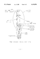
- FIG. 1 shows the configuration of a typical mercury-vapor lamp. This figure is provided only for demonstration purposes since there are a variety of different types of mercury-vapor lamps.
- the mercury-vapor lamp consists of an arc tube 110 which is filled with argon gas and a small amount of pure mercury.
- Arc tube 110 is mounted inside a large outer bulb 120 which encloses and protects the arc tube. Additionally, the outer bulb may be coated with phosphors to improve the color of the light emitted and reduce the ultraviolet radiation emitted.
- Mounting of arc tube 110 inside outer bulb 120 may be accomplished with an arc tube mount support 130 on the top and a stem 140 on the bottom.
- Main electrodes 150a and 150b are mechanically sealed at both ends of arc tube 110.
- the mercury-vapor lamp requires a sizeable voltage to start the arc between main electrodes 150a and 150b.
- the starting of the mercury-vapor lamp is controlled by a starting circuit (not shown in FIG. 1) which is attached between the power source (not shown in FIG. 1) and the lamp.
- a starting circuit (not shown in FIG. 1) which is attached between the power source (not shown in FIG. 1) and the lamp.
- the lamp current will continue to increase unless the starting circuit provides some means for limiting the current.
- the lamp current is limited by a resistor, which severely reduces the efficiency of the circuit, or by a magnetic device, such as a choke or a transformer, called a ballast.
- the mercury-vapor lamp may require minutes of warm-up before light is emitted. Additionally, if power is lost, the lamp must cool and the mercury pressure must decrease before the starting arc can start again.
- the mercury-vapor lamp has become the predominant street lamp with millions of units produced annually.
- the current installed base of these street lamps is enormous with more than 500,000 street lamps in Los Angeles alone.
- the mercury-vapor lamp is not the most efficient gaseous discharge lamp, but is preferred for use in street lamps because of its long life, reliable performance, and relatively low cost.
- FIG. 2 shows a lamp arrangement 201 with a typical lamp sensor unit 210 which is situated between a power source 220 and a lamp assembly 230.
- Lamp assembly 230 includes a lamp 240 (such as the mercury-vapor lamp presented in FIG. 1) and a starting circuit 250.
- a typical street lamp assembly 201 includes a lamp sensor unit 210 which in turn includes a light sensor 260 and a relay 270 as shown in FIG. 2.
- Lamp sensor unit 210 is electrically coupled between external power source 220 and starting circuit 250 of lamp assembly 230.
- there is a switched line 280c and a neutral line 280d providing electrical connection between lamp sensor unit 210 and starting circuit 250 of lamp assembly 230.
- lamp sensor units 210 use a standard three prong plug, for example a twist lock plug, to connect to the back of lamp assembly 230.
- the three prongs couple to hot line 280a, switched line 280c, and neutral lines 280b and 280d.
- the neutral lines 280b and 280d are both connected to the same physical prong since they are at the same electrical potential.
- Some systems also have a ground wire, but no ground wire is shown in FIG. 2 since it is not relevant to the operation of lamp sensor unit 210.
- Power source 220 may be a standard 115 Volt, 60 Hz source from a power line. Of course, a variety of alternatives are available for power source 220. In foreign countries, power source 220 may be a 220 Volt, 50 Hz source from a power line. Additionally, power source 220 may be a DC voltage source or, in certain remote regions, it may be a battery which is charged by a solar reflector.
- lamp sensor unit 210 The operation of lamp sensor unit 210 is fairly simple. At sunset, when the light from the sun decreases below a sunset threshold, the light sensor 260 detects this condition and causes relay 270 to close. Closure of relay 270 results in electrical connection of hot line 280a and switched line 280c with power being applied to starting circuit 250 of lamp assembly 230 to ultimately produce light from lamp 240. At sunrise, when the light from the sun increases above a sunrise threshold, light sensor 260 detects this condition and causes relay 270 to open. Opening of relay 270 eliminates electrical connection between hot line 280a and switched line 280c and causes the removal of power from starting circuit 250 which turns lamp 240 off.
- Lamp sensor unit 210 provides an automated, distributed control mechanism to turn lamp assembly 230 on and off. Unfortunately, it provides no mechanism for centralized monitoring of the street lamp to determine if the lamp is functioning properly. This problem is particularly important in regard to the street lamps on major boulevards and highways in large cities. When a street lamp burns out over a highway, it is often not replaced for a long period of time because the maintenance crew will only schedule a replacement lamp when someone calls the city maintenance department and identifies the exact pole location of the bad lamp. Since most automobile drivers will not stop on the highway just to report a bad street lamp, a bad lamp may go unreported indefinitely.
- hidden problems relate to current, when the lamp is drawing significantly more current than is normal, or voltage, when the power supply is not supplying the appropriate voltage level to the street lamp.
- the present system of lamp control in which an individual light sensor is located at each street lamp is a distributed control system which does not allow for centralized control. For example, if the city wanted to turn on all of the street lamps in a certain area at a certain time, this could not be done because of the distributed nature of the present lamp control circuits.
- RadioSwitch made by Cetronic.
- the RadioSwitch is a remotely controlled time switch for installation on the DIN-bar of control units. It is used for remote control of electrical equipment via local or national paging networks. Unfortunately, the RadioSwitch is unable to address most of the problems listed above.
- the RadioSwitch Since the RadioSwitch is receive only (no transmit capability), it only allows one to remotely control external equipment. Furthermore, since the communication link for the RadioSwitch is via paging networks, it is unable to operate in areas in which paging does not exist (for example, large rural areas in the United States). Additionally, although the RadioSwitch can be used to control street lamps, it does not use the standard three prong interface used by the present lamp control units. Accordingly, installation is difficult because it cannot be used as a plug-in replacement for the current lamp control units.
- the present invention provides a lamp monitoring and control unit and method for use with street lamps which solves the problems described above.
- a lamp monitoring and control unit comprising: a processing and sensing unit for sensing at least one lamp parameter of an associated lamp, and for processing the at least one lamp parameter to monitor and control the associated lamp by outputting monitoring data and control information; and a transmit unit for transmitting the monitoring data, representing the at least one lamp parameter, from the processing and sensing unit.
- a lamp monitoring and control unit comprising: a processing unit for processing at least one lamp parameter and outputting a relay control signal; a light sensor, coupled to the processing unit, for sensing an amount of ambient light, producing a light signal associated with the amount of ambient light, and outputting the light signal to the processing unit; a relay for switching a switched power line to a hot power line based upon the relay control signal from the processing unit; a voltage sensor, coupled to the processing unit, for sensing a switched voltage in the switched power line; a current sensor, coupled to the switched power line, for sensing a switched current in the switched power line; and a transmit unit for transmitting monitoring data, representing the at least one lamp parameter, from the processing unit.
- a method for monitoring and controlling a lamp comprising the steps of: sensing at least one lamp parameter of an associated lamp; processing the at least one lamp parameter to produce monitoring data and control information; transmitting the monitoring data; and applying the control information.
- a feature of the present invention is that the lamp monitoring and control unit may be coupled to the associated lamp via a standard three prong plug.
- processing and sensing unit may include a relay for switching the switched power line to the hot power line.
- the processing and sensing unit may include a current sensor for sensing a switched current in the switched power line.
- the processing and sensing unit may include a voltage sensor for sensing a switched voltage in the switched power line.
- the transmit unit may include a transmitter and a modified directional discontinuity ring radiator, and the modified directional discontinuity ring radiator may include a plurality of loops for resonance at a desired frequency range.
- the step of processing may include providing an initial delay, a current stabilization delay, a relay settle delay, to prevent false triggering.
- the step of transmitting the monitoring data may include a pseudo-random reporting start time delay, reporting delta time, and frequency.
- the pseudo-random nature of these values may be based on the serial number of the lamp monitoring and control unit.
- An advantage of the present invention is that it solves the problem of providing centralized monitoring and/or control of the street lamps in a geographical area.
- Another advantage of the present invention is that by using the standard three prong plug of the current street lamps, it is easy to install in place of the millions of currently installed lamp control units.
- An additional advantage of the present invention is that it provides for a new type of monitoring and control unit which allows centralized monitoring and/or control of units distributed over a large geographical area.
- FIG. 1 shows the configuration of a typical mercury-vapor lamp.
- FIG. 2 shows a typical configuration of a lamp arrangement comprising a lamp sensor unit situated between a power source and a lamp assembly.
- FIG. 3 shows a lamp arrangement, according to one embodiment of the invention, comprising a lamp monitoring and control unit situated between a power source and a lamp assembly.
- FIG. 4 shows a lamp monitoring and control unit, according to another embodiment of the invention, including a processing and sensing unit, a Tx unit, and an Rx unit.
- FIG. 5 shows a lamp monitoring and control unit, according to another embodiment of the invention, including a processing and sensing unit, a Tx unit, an Rx unit, and a light sensor.
- FIG. 6 shows a lamp monitoring and control unit, according to another embodiment of the invention, including a processing and sensing unit, a Tx unit, and a light sensor.
- FIG. 7 shows a lamp monitoring and control unit, according to another embodiment of the invention, including a microprocessing unit, an A/D unit, a current sensing unit, a voltage sensing unit, a relay, a Tx unit, and a light sensor.
- FIG. 8 shows an example frequency channel plan for a lamp monitoring and control unit, according to another embodiment of the invention.
- FIG. 9 shows a typical directional discontinuity ring radiator (DDRR) antenna.
- FIG. 10 shows a modified DDRR antenna, according to another embodiment of the invention.
- FIGS. 11A-E show methods for one implementation of logic for a lamp monitoring and control unit, according to another embodiment of the invention.
- LMCU lamp monitoring and control unit
- method which allows centralized monitoring and/or control of street lamps, will now be described with reference to the accompanying figures. While the invention is described with reference to an LMCU, the invention is not limited to this application and can be used in any application which requires a monitoring and control unit for centralized monitoring and/or control of devices distributed over a large geographical area. Additionally, the term street lamp in this disclosure is used in a general sense to describe any type of street lamp, area lamp, or outdoor lamp.
- FIG. 3 shows a lamp arrangement 301 which includes lamp monitoring and control unit 310, according to one embodiment of the invention.
- Lamp monitoring and control unit 310 is situated between a power source 220 and a lamp assembly 230.
- Lamp assembly 230 includes a lamp 240 and a starting circuit 250.
- Power source 220 may be a standard 115 volt, 60 Hz source supplied by a power line. It is well known to those skilled in the art that a variety of alternatives are available for power source 220. In foreign countries, power source 220 may be a 220 volt, 50 Hz source from a power line. Additionally, power source 220 may be a DC voltage source or, in certain remote regions, it may be a battery which is charged by a solar reflector.
- lamp sensor unit 210 included a light sensor 260 and a relay 270 which is used to control lamp assembly 230 by automatically switching the hot power 280a to a switched power line 280c depending on the amount of ambient light received by light sensor 260.
- lamp monitoring and control unit 310 provides several functions including a monitoring function which is not provided by lamp sensor unit 210.
- Lamp monitoring and control unit 310 is electrically located between the external power supply 220 and starting circuit 250 of lamp assembly 230. From an electrical standpoint, there is a hot 280a with a neutral 280b electrical connection between power supply 220 and lamp monitoring and control unit 310. Additionally, there is a switched 280c and a neutral 280d electrical connection between lamp monitoring and control unit 310 and starting circuit 250 of lamp assembly 230.
- lamp monitoring and control unit 310 may use a standard three-prong plug to connect to the back of lamp assembly 230.
- the three prongs in the standard three-prong plug represent hot 280a, switched 280c, and neutral 280b and 280d.
- the neutral lines 280b and 280d are both connected to the same physical prong and share the same electrical potential.
- FIG. 4 shows lamp monitoring and control unit 310, according to another embodiment of the invention.
- Lamp monitoring and control unit 310 includes a processing and sensing unit 412, a transmit (TX) unit 414, and an optional receive (RX) unit 416.
- Processing and sensing unit 412 is electrically connected to hot 280a, switched 280c, and neutral 280b and 280d electrical connections. Furthermore, processing and sensing unit 412 is connected to TX unit 414 and RX unit 416.
- TX unit 414 may be used to transmit monitoring data and RX unit 416 may be used to receive control information.
- RX unit 416 may be deleted from lamp monitoring and control unit 310.
- FIG. 5 shows a lamp monitoring and control unit 310, according to another embodiment of the invention, with a configuration similar to that shown in FIG. 4.
- lamp monitoring and control unit 310 of FIG. 5 further includes a light sensor 518, analogous to light sensor 216 of FIG. 2, which allows for some degree of local control.
- Light sensor 518 is coupled to processing and sensing unit 412 to provide information regarding the level of ambient light. Accordingly, processing and sensing unit 412 may receive control information either locally from light sensor 518 or remotely from RX unit 416.
- FIG. 6 shows another configuration for lamp monitoring control unit 310, according to another embodiment of the invention, but without RX unit 416.
- This embodiment of lamp monitoring and control unit 310 can be used in applications in which only local control information, for example from light sensor 518, is to be passed to processing and sensing unit 412.
- remote monitoring data may be received via TX unit 414 and local control information may be generated via light sensor 518.
- FIG. 7 shows a more detailed implementation of lamp monitoring and control unit 310 of FIG. 6, according to one embodiment of the invention.
- FIG. 7 shows one embodiment of a lamp monitoring and control unit 310 with a three-prong plug 720 to provide hot 280a, neutral 280b and 280d, and switched 280c electrical connections.
- the hot 280a and neutral 280b and 280d electrical connections are connected to an optional switching power supply 710 in applications in which AC power is input and DC power is required to power the circuit components of lamp monitoring and control unit 310.
- Light sensor 518 includes a photosensor 518a and associated light sensor circuitry 518b.
- TX unit 414 includes a radio modem transmitter 414a and a built-in antenna 414b.
- Processing and sensing unit 412 includes microprocessor circuitry 412a, a relay 412b, current and voltage sensing circuitry 412c, and an analog-to-digital converter 412d.
- Microprocessor circuitry 412a includes any standard microprocessor/microcontroller such as the Intel 8751 or Motorola 68HC16. Additionally, in applications in which cost is an issue, microprocessor circuitry 412a may comprise a small, low cost processor with built-in memory such as the Microchip PIC 8 bit microcontroller. Furthermore, microprocessor circuitry 412a may be implemented by using a PAL, EPLD, FPGA, or ASIC device.
- Microprocessor circuitry 412a receives and processes input signals and outputs control signals. For example, microprocessor circuitry 412a receives a light sensing signal from light sensor 518. This light sensing signal may either be a threshold indication signal, that is, providing a digital signal, or some form of analog signal.
- microprocessor circuitry 412a may alternatively or additionally execute software to output a relay control signal to a relay 412a which switches switched power line 280c to hot power line 280a.
- Microprocessor circuitry 412a may also interface to other sensing circuitry.
- the lamp monitoring and control unit 310 may include current and voltage sensing circuitry 412c which senses the voltage of the switched power line 280c and also senses the current flowing through the switched power line 280c.
- the voltage sensing operation may produce a voltage ON signal which is sent from the current and voltage sensing circuitry 412c to microprocessor circuitry 412a.
- This voltage ON signal can be of a threshold indication, that is, some form of digital signal, or it can be an analog signal.
- Current and voltage sensing circuitry 412c can also output a current level signal indicative of the amount of current flowing through switched power line 280c.
- the current level signal can interface directly to microprocessor circuitry 412a or, alternatively, it can be coupled to microprocessing circuitry 412a through an analog-to-digital converter 412b.
- Microprocessor circuitry 412a can produce a CLOCK signal which is sent to analog-to-digital converter 412d and which is used to allow A/D data to pass from analog-to-digital converter 412d to microprocessor circuitry 412a.
- Microprocessor circuitry 412a can also be coupled to radio modem transmitter 414a to allow monitoring data to be sent from lamp monitoring control unit 310.
- FIG. 7 The configuration shown in FIG. 7 is intended as an illustration of one way in which the present invention can be implemented.
- analog-to-digital converter 412b may be combined into microprocessor circuitry 412a for some applications.
- the memory for microprocessor circuitry 412a may either be internal to the microprocessor circuitry or contained as an external EPROM, EEPROM, Flash RAM, dynamic RAM, or static RAM.
- Current and voltage sensor circuitry 412c may either be combined in one unit with shared components or separated into two separate units.
- the current sensing portion of current and voltage sensing circuitry 412c may include a current sensing transformer 413 and associated circuitry as shown in FIG. 7 or may be configured using different circuitry which also senses current.
- the frequencies to be used by the TX unit 414 are selected by microprocessor circuitry 412a. There are a variety of ways that these frequencies can be organized and used, examples of which will be discussed below.
- FIG. 8 shows an example of a frequency channel plan for lamp monitoring and control unit 310, according to one embodiment of the invention.
- interactive video and data service (VDS) radio frequencies in the range of 218-219 MHz are shown.
- the IVDS channels in FIG. 8 are divided into two groups, Group A and Group B, with each group having nineteen channels spaced at 25 KHz steps.
- the first channel of the group A frequencies is located at 218.025 MHz and the first channel of the group B frequencies is located at 218.525 MHz.
- the mapping between channel numbers and frequencies can either be performed in microprocessor circuitry 412a or TX unit 414.
- the data signal sent to TX unit 414 from microprocessor circuitry 412a may either consist of channel numbers or frequency data.
- TX unit 414 To transmit at these frequencies, TX unit 414 must have an associated antenna 414b.
- FIG. 9 shows a typical directional discontinuity ring radiator (DDRR) antenna 900.
- DDRR antenna 900 is well known to those skilled in the art, and detailed description of the operation and use of this antenna can be found in the American Radio Relay League (ARRL) Handbook, the appropriate sections of which are incorporated by reference.
- ARRL American Radio Relay League
- the problem with using DDRR antenna 900 in applications such as lamp monitoring and control unit 310 is that the antenna dimension for resonance in certain frequency ranges, such as the IVDS frequency range, is too large.
- FIG. 10 shows a modified DDRR antenna 1000, according to a further embodiment of the invention.
- Modified DDRR antenna 1000 is mounted on a PC board 1010 and includes a metal shield 1020, a coil segment 1060, a looped wire coil 1040, a first variable capacitor C1, and a second variable capacitor C2. Additionally, a plastic assembly (not shown) may be included in modified DDRR antenna 1000 to hold looped wire coil 1040 in place.
- variable capacitor C2 is used to match the input impedance of modified DDRR antenna 1000 to 50 ohms.
- Looped wire coil 1040 is looped several times, as opposed to typical DDRR antenna 900 which only has one loop. Looped wire coil 1040 may be coupled to wire segment 1060, or both looped wire coil 1040 and wire segment 1060 may be part of a continuous piece of wire, as shown. The end of wire coil 1040 is coupled to capacitor C1 which tunes modified DDRR antenna 1000 for resonance at the desired frequency.
- Modified DDRR antenna 1000 has multiple loops in wire coil 1040 which allow the antenna to resonate at particular frequencies. For example, if typical DDRR antenna 900 with approximately a 5' diameter is modified to include three to six loops, then the diameter can be decreased to less than 4' and still resonate in the IVDS frequency range. In other words, if typical DDRR antenna 900 has a 4' diameter, it will have poor resonance in the IVDS frequency range. In contrast, if modified DDRR antenna 1000 has a 4' diameter, it will have excellent resonance in the IVDS frequency range.
- modified DDRR antenna 1000 provides for an efficient transformation of input RF energy for radiation as an E-M field because of its improved resonance at the desired frequencies and an impedance match (such as 50 ohms) to the input RF source.
- the exact number of additional loops and spacing for modified DDRR antenna 1000 depends on the frequency range selected.
- modified DDRR antenna 1000 can be shared by TX unit 414 and RX unit 416.
- RX unit 416 and TX unit 414 may use separate antennas.
- FIGS. 11A-E show methods for implementation of logic for lamp monitoring and control unit 310, according to a further embodiment of the invention. These methods may be implemented in a variety of ways, including software in microprocessor circuitry 412a or customized logic chips.
- FIG. 11A shows one method for energizing and de-energizing a street lamp and transmitting associated monitoring data.
- the method of FIG. 11A shows a single transmission for each control event.
- the method begins with a start block 1100 and proceeds to step 1110 which involves checking AC and Daylight Status .
- the Check AC and Daylight Status step 1110 is used to check for conditions where the AC power and/or the Daylight Status have changed. If a change does occur, the method proceeds to the step 1120 which is a decision block based on the change.
- step 1120 proceeds to a Debounce Delay step 1122 which involves inserting a Debounce Delay.
- the Debounce Delay may be 0.5 seconds.
- the method leads back to Check AC and Daylight Status step 1110.
- step 1120 proceeds to step 1130 which is a decision block to determine whether the lamp should be energized. If the lamp should be energized, then the method proceeds to step 1132 which turns the lamp on. After step 1132 when the lamp is turned on, the method proceeds to step 1134 which involves Current Stabilization Delay to allow the current in the street lamp to stabilize. The amount of delay for current stabilization depends upon the type of lamp used. However, for a typical vapor lamp a ten minute stabilization delay is appropriate. After step 1134, the method leads back to step 1110 which checks AC and Daylight Status.
- step 1140 is a decision block to check to deenergize the lamp. If the lamp is to be deenergized, the method proceeds to step 1142 which involves turning the Lamp Off. After the lamp is turned off, the method proceeds to step 1144 in which the relay is allowed a Settle Delay time. The Settle Delay time is dependent upon the particular relay used and may be, for example, set to 0.5 seconds. After step 1144, the method returns to step 1110 to check the AC and Daylight Status.
- step 1140 if the lamp is not to be deenergized, the method proceeds to step 1150 in which an error bit is set, if required and proceeds to step 1160 in which an A/D is read.
- the A/D may be the analog-to-digital converter 412d for reading the current level as shown in FIG. 7.
- step 1160 the method then proceeds from step 1160 to step 1170 which checks to see if a transmit is required. If no transmit is required, the method proceeds to step 1172 in which a Scan Delay is executed.
- the Scan Delay depends upon the circuitry used and, for example, may be 0.5 seconds. After step 1172, the method returns to step 1110 which checks AC and Daylight Status.
- step 1170 if a transmit is required, then the method proceeds to step 1180 which performs a transmit operation. After the transmit operation of step 1180 is completed, the method then returns to step 1110 which checks AC and Daylight Status.
- FIG. 11B is analogous to FIG. 11A with one modification. This modification occurs after step 1120. If a change has occurred, rather than simply executing step 1122, the Debounce Delay, the method performs a further step 1124 which involves checking whether daylight has occurred. If daylight has not occurred, then the method proceeds to step 1126 which executes an Initial Delay. This initial delay may be, for example, 0.5 seconds. After step 1126, the method proceeds to step 1122 and follows the same method as shown in FIG. 11A.
- step 1128 executes an Initial Delay.
- the Initial Delay associated with step 1128 should be a significantly larger value than the Initial Delay associated with step 1126. For example, an Initial Delay of 45 seconds may be used.
- the Initial Delay of step 1128 is used to prevent a false triggering which deenergizes the lamp. In actual practice, this extended delay can become very important because if the lamp is inadvertently deenergized too soon, it requires a substantial amount of time to deenergize the lamp (for example, ten minutes).
- step 1122 executes a Debounce Delay and then returns to step 1110 as shown in FIGS. 11A and 11B.
- FIG. 11C shows a method for transmitting monitoring data multiple times in a lamp monitoring and control unit, according to a further embodiment of the invention. This method is particularly important in applications in which lamp monitoring and control unit 310 does not have a RX unit 416 for receiving acknowledgements of transmissions.
- the method begins with a transmit start block 1182 and proceeds to step 1184 which involves initializing a count value, i.e. setting the count value to zero.
- Step 1184 proceeds to step 1186 which involves setting a variable x to a value associated with a serial number of lamp monitoring and control unit 310.
- variable x may be set to 50 times the lowest nibble of the serial number.
- Step 1186 proceeds to step 1188 which involves waiting a reporting start time delay associated with the value x.
- the reporting start time is the amount of delay time before the first transmission. For example, this delay time may be set to x seconds where x is an integer between 1 and 32,000 or more.
- Step 1188 proceeds to step 1190 in which a variable y representing a channel number is set.
- y may be set to the integer value of RTC/12.8, where RTC represents a real time clock counting from 0-255 as fast as possible.
- the RTC may be included in microprocessing circuitry 412a.
- Step 1190 proceeds to step 1192 in which a packet is transmitted on channel y.
- Step 1192 proceeds to step 1194 in which the count value is incremented.
- Step 1194 proceeds to step 1196 which is a decision block to determine if the count value equals an upper limit N.
- step 1196 returns to step 1188 and waits another delay time associated with variable x.
- This delay time is the reporting delta time since it represents the time difference between two consecutive reporting events.
- step 1196 proceeds to step 1198 which is an end block.
- the value for N must be determined based on the specific application. Increasing the value of N decreases the probability of a unsuccessful transmission since the same data is being sent multiple times and the probability of all of the packets being lost decreases as N increases. However, increasing the value of N increases the amount of traffic which may become an issue in a lamp monitoring and control system with a plurality of lamp monitoring and control units.
- FIG. 11D shows a method for transmitting monitoring data multiple times in a monitoring and control unit according to a another embodiment of the invention.
- the method begins with a transmit start block 1110' and proceeds to step 1112' which involves initializing a count value, i.e., setting the count value to 1.
- the method proceeds from step 1112' to step 1114' which involves randomizing the reporting start time delay.
- the reporting start time delay is the amount of time delay required before the transmission of the first data packet.
- a variety of methods can be used for this randomization process such as selecting a pseudo-random value or basing the randomization on the serial number of monitoring and control unit 510.
- the method proceeds from step 1114' to step 1116' which involves checking to see if the count equals 1. If the count is equal to 1, then the method proceeds to step 1120' which involves setting a reporting delta time equal to the reporting start time delay.
- step 1118' involves randomizing the reporting delta time.
- the reporting delta time is the difference in time between each reporting event.
- a variety of methods can be used for randomizing the reporting delta time including selecting a pseudo-random value or selecting a random number based upon the serial number of the monitoring and control unit 510.
- step 1122' which involves randomizing a transmit channel number.
- the transmit channel number is a number indicative of the frequency used for transmitting the monitoring data.
- There are a variety of methods for randomizing the transmit channel number such as selecting a pseudo-random number or selecting a random number based upon the serial number of the monitoring and control unit 510.
- step 1124' which involves waiting the reporting delta time.
- the reporting delta time is the time which was selected during the randomization process of step 1118' or the reporting start time delay selected in step 1114', if the count equals 1.
- the use of separate randomization steps 1114' and 1118' is important because it allows the use of different randomization functions for the reporting start time delay and the reporting delta time, respectively.
- step 1124' the method proceeds to step 1126' which involves transmitting a packet on the transmit channel selected in step 1122'.
- step 1126' proceeds from step 1126' to step 1128' which involves incrementing the counter for the number of packet transmissions.
- step 1128' the count is compared with a value N which represents the maximum number of transmissions for each packet. If the count is less than or equal to N, then the method proceeds from step 1130' back to step 1118' which involves randomizing the reporting delta time for the next transmission. If the count is greater than N, then the method proceeds from step 1130' to the end block 1132' for the transmission method.
- the method will continue transmission of the same packet of data N times, with randomization of the reporting start time delay, randomization of the reporting delta times between each reporting event, and randomization of the transmit channel number for each packet.
- These multiple randomizations help stagger the packets in the frequency and time domain to reduce the probability of collisions of packets from different monitoring and control units.
- FIG. 11E shows a further method for transmitting monitoring data multiple times from a monitoring and control unit 510, according to another embodiment of the invention.
- the method begins with a transmit start block 1140' and proceeds to step 1142' which involves initializing a count value, i.e., setting the count value to 1.
- the method proceeds from step 1142' to step 1144' which involves reading an indicator, such as a group jumper, to determine which group of frequencies to use, Group A or B. Examples of Group A and Group B channel numbers and frequencies can be found in FIG. 8.
- Step 1144' proceeds to step 1146' which makes a decision based upon whether Group A or B is being used. If Group A is being used, step 1146' proceeds to step 1148' which involves setting a base channel to the appropriate frequency for Group A. If Group B is to be used, step 1146' proceeds to step 1150' which involves setting the base channel frequency to a frequency for Group B.
- Step 1152' involves randomizing a reporting start time delay.
- the randomization can be achieved by multiplying the lowest nibble of the serial number of monitoring and control unit 510 by 50 and using the resulting value, x, as the number of milliseconds for the reporting start time delay.
- step 1152' The method proceeds from step 1152' to step 1154' which involves waiting x number of seconds as determined in step 1152'.
- step 1156' proceeds to step 1158' which determines whether the count equals 1. If the count equals 1, the method proceeds from step 1158' to step 1172' which involves transmitting the packet on a channel determined from the base channel frequency selected in either step 1148' or step 1150' plus the channel frequency offset selected in step 1156'.
- step 1158' determines whether the count is equal to N, where N represents the maximum number of packet transmissions. If the count is equal to N, then the method proceeds from step 1160' to step 1172' which involves transmitting the packet on a channel determined from the base channel frequency selected in either step 1148' or step 1150' plus the channel number offset selected in step 1156'.
- step 1160' If the count is not equal to N, indicating that the count is a value between 1 and N, then the method proceeds from step 1160' to step 1162' which involves reading a real time counter (RTC) which may be located in processing and sensing unit 412.
- RTC real time counter
- step 1162' The method proceeds from step 1162' to step 1164' which involves comparing the RTC value against a maximum value, for example, a maximum value of 152. If the RTC value is greater than or equal to the maximum value, then the method proceeds from step 1164' to step 1166' which involves waiting x seconds and returning to step 1162'.
- a maximum value for example, a maximum value of 152.
- step 1164' the method proceeds from step 1164' to step 1168' which involves setting a value y equal to a value indicative of the channel number offset.
- y can be set to an integer of the real time counter value divided by 8, so that Y value would range from 0 to 18.
- step 1168' The method proceeds from step 1168' to step 1170' which involves computing a frequency offset value z from the channel number offset value y. For example, if a 25 KHz channel is being used, then z is equal to y times 25 KHz.
- step 1170' which involves transmitting the packet on a channel determined from the base channel frequency selected in either step 1148' or step 1150' plus the channel frequency offset computed in step 1170'.
- step 1172' proceeds from step 1172' to step 1174' which involves incrementing the count value.
- step 1174' proceeds from step 1174' to step 1176' which involves comparing the count value to a value N+1 which is related to the maximum number of transmissions for each packet. If the count is not equal to N+1, the method proceeds from step 1176' back to step 1154' which involves waiting x number of milliseconds. If the count is equal to N+1, the method proceeds from step 1176' to the end block 1178'.
- the method shown in FIG. 11E is similar to that shown in FIG. 11D, but differs in that it requires the first and the Nth transmission to occur at the base frequency rather than a randomly selected frequency.
- FIG. 4 shows a light monitoring and control unit 310 in which there is no light sensor but rather an RX unit 416 for receiving control information.
- Light monitoring and control unit 310 may be used in an environment in which a centralized control system is preferred. For example, instead of having a decentralized light sensor at every location, light monitoring and control unit 310 of FIG. 4 allows for a centralized control mechanism.
- RX unit 416 could receive centralized energize/deenergize signals which are sent to all of the street lamp assemblies in a particular geographic region.
- processing and sensing unit 412 may contain a table with a listing of sunrise and sunset times for a yearly cycle. The sunrise and sunset times could be used to energize and deenergize the lamp without the need for either RX unit 416 or light sensor 518.
Landscapes
- Engineering & Computer Science (AREA)
- Computer Networks & Wireless Communication (AREA)
- Circuit Arrangement For Electric Light Sources In General (AREA)
Abstract
Description
Claims (55)
Priority Applications (11)
| Application Number | Priority Date | Filing Date | Title |
|---|---|---|---|
| US08/838,302 US6119076A (en) | 1997-04-16 | 1997-04-16 | Lamp monitoring and control unit and method |
| US08/942,681 US6359555B1 (en) | 1997-04-16 | 1997-10-02 | Alarm monitoring and control system and method |
| AU74664/98A AU7466498A (en) | 1997-04-16 | 1998-04-15 | Monitoring and control systems and methods |
| PCT/US1998/007498 WO1998047120A1 (en) | 1997-04-16 | 1998-04-15 | Monitoring and control systems and methods |
| US09/501,274 US6393381B1 (en) | 1997-04-16 | 2000-02-09 | Lamp monitoring and control unit and method |
| US09/605,027 US6456960B1 (en) | 1997-04-16 | 2000-06-28 | Lamp monitoring and control unit and method |
| US09/637,916 US6384722B1 (en) | 1997-04-16 | 2000-08-14 | Lamp monitoring and control system and method |
| US10/100,091 US6636150B2 (en) | 1997-04-16 | 2002-03-19 | Lamp monitoring and control system and method |
| US10/811,855 US6889174B2 (en) | 1997-04-16 | 2004-03-30 | Remotely controllable distributed device monitoring unit and system |
| US11/117,518 US7113893B2 (en) | 1997-04-16 | 2005-04-29 | Lamp monitoring and control unit and method |
| US11/526,796 US20070021946A1 (en) | 1997-04-16 | 2006-09-26 | Lamp monitoring and control unit and method |
Applications Claiming Priority (1)
| Application Number | Priority Date | Filing Date | Title |
|---|---|---|---|
| US08/838,302 US6119076A (en) | 1997-04-16 | 1997-04-16 | Lamp monitoring and control unit and method |
Related Child Applications (4)
| Application Number | Title | Priority Date | Filing Date |
|---|---|---|---|
| US08/838,303 Continuation-In-Part US6035266A (en) | 1997-04-16 | 1997-04-16 | Lamp monitoring and control system and method |
| US08/942,681 Continuation-In-Part US6359555B1 (en) | 1997-04-16 | 1997-10-02 | Alarm monitoring and control system and method |
| US09/501,274 Division US6393381B1 (en) | 1997-04-16 | 2000-02-09 | Lamp monitoring and control unit and method |
| US10/251,756 Division US6714895B2 (en) | 1997-04-16 | 2002-09-23 | Lamp monitoring and control unit and method |
Publications (1)
| Publication Number | Publication Date |
|---|---|
| US6119076A true US6119076A (en) | 2000-09-12 |
Family
ID=25276765
Family Applications (3)
| Application Number | Title | Priority Date | Filing Date |
|---|---|---|---|
| US08/838,302 Expired - Lifetime US6119076A (en) | 1997-04-16 | 1997-04-16 | Lamp monitoring and control unit and method |
| US09/501,274 Expired - Lifetime US6393381B1 (en) | 1997-04-16 | 2000-02-09 | Lamp monitoring and control unit and method |
| US09/605,027 Expired - Lifetime US6456960B1 (en) | 1997-04-16 | 2000-06-28 | Lamp monitoring and control unit and method |
Family Applications After (2)
| Application Number | Title | Priority Date | Filing Date |
|---|---|---|---|
| US09/501,274 Expired - Lifetime US6393381B1 (en) | 1997-04-16 | 2000-02-09 | Lamp monitoring and control unit and method |
| US09/605,027 Expired - Lifetime US6456960B1 (en) | 1997-04-16 | 2000-06-28 | Lamp monitoring and control unit and method |
Country Status (1)
| Country | Link |
|---|---|
| US (3) | US6119076A (en) |
Cited By (44)
| Publication number | Priority date | Publication date | Assignee | Title |
|---|---|---|---|---|
| US20020009975A1 (en) * | 2000-06-07 | 2002-01-24 | Janusz Gerald E. | Method and system for transmitting, receiving and collecting information related to a plurality of working components |
| US20020049974A1 (en) * | 2000-10-05 | 2002-04-25 | J. Mitchell Shnier | Methods for creating a customized program from a variety of sources |
| US6393382B1 (en) * | 1997-04-16 | 2002-05-21 | A. L. Air Data, Inc. | Lamp monitoring and control system and method |
| US6452340B1 (en) * | 1999-04-09 | 2002-09-17 | Acuity Brands, Inc. | Luminaire starting aid device |
| US6452339B1 (en) * | 1997-08-19 | 2002-09-17 | Acuity Brands, Inc. | Photocontroller diagnostic system |
| US6456960B1 (en) * | 1997-04-16 | 2002-09-24 | A.L. Air Data, Inc. | Lamp monitoring and control unit and method |
| US20030122680A1 (en) * | 2001-12-31 | 2003-07-03 | Ardelan John Patrick | Integrated radio tower light controller and alarm reporting device |
| US6636005B2 (en) | 2001-11-14 | 2003-10-21 | Koninklijke Philips Eletronics N.V. | Architecture of ballast with integrated RF interface |
| US6714895B2 (en) * | 2000-06-28 | 2004-03-30 | A.L. Air Data, Inc. | Lamp monitoring and control unit and method |
| US20040080878A1 (en) * | 2002-10-29 | 2004-04-29 | Siet S.R.L. | Protection device for transformers particularly for supplying power to lamps |
| US20040254725A1 (en) * | 2001-11-19 | 2004-12-16 | Eric Douville | System for locating and addressing the lights of a beacon network |
| US20050179404A1 (en) * | 2004-02-13 | 2005-08-18 | Dragan Veskovic | Multiple-input electronic ballast with processor |
| US20050210134A1 (en) * | 2002-11-29 | 2005-09-22 | Jay Jayapalan | Method and device for providing more accurate subscriber billing |
| EP1650870A3 (en) * | 2004-10-22 | 2007-11-14 | Domoblue, S.L. | Device, system and installation to control electrical power supplied to a load |
| US7333903B2 (en) | 2005-09-12 | 2008-02-19 | Acuity Brands, Inc. | Light management system having networked intelligent luminaire managers with enhanced diagnostics capabilities |
| GB2447912A (en) * | 2007-03-27 | 2008-10-01 | Lucy & Company Ltd W | Improvements in or relating to area lighting |
| US20090066540A1 (en) * | 2007-09-07 | 2009-03-12 | Dimitri Marinakis | Centralized route calculation for a multi-hop streetlight network |
| US20090066258A1 (en) * | 2007-09-07 | 2009-03-12 | Streetlight Intelligence, Inc. | Streelight monitoring and control |
| US7650425B2 (en) | 1999-03-18 | 2010-01-19 | Sipco, Llc | System and method for controlling communication between a host computer and communication devices associated with remote devices in an automated monitoring system |
| US7697492B2 (en) | 1998-06-22 | 2010-04-13 | Sipco, Llc | Systems and methods for monitoring and controlling remote devices |
| US7756086B2 (en) | 2004-03-03 | 2010-07-13 | Sipco, Llc | Method for communicating in dual-modes |
| US7817063B2 (en) | 2005-10-05 | 2010-10-19 | Abl Ip Holding Llc | Method and system for remotely monitoring and controlling field devices with a street lamp elevated mesh network |
| US20110012539A1 (en) * | 2009-07-15 | 2011-01-20 | Gary Skwarlo | Time-Delayed Power Switching Device and Methods of Use |
| US20110057570A1 (en) * | 2005-06-30 | 2011-03-10 | Streetlight Intelligence, Inc. | Method and System for Luminance Characterization |
| US20110185349A1 (en) * | 2010-01-28 | 2011-07-28 | Empower Electronics, Inc. | Lamp ballast configured to operate in a self-forming network |
| US8000314B2 (en) | 1996-12-06 | 2011-08-16 | Ipco, Llc | Wireless network system and method for providing same |
| US8013732B2 (en) | 1998-06-22 | 2011-09-06 | Sipco, Llc | Systems and methods for monitoring and controlling remote devices |
| US8031650B2 (en) | 2004-03-03 | 2011-10-04 | Sipco, Llc | System and method for monitoring remote devices with a dual-mode wireless communication protocol |
| US8064412B2 (en) | 1998-06-22 | 2011-11-22 | Sipco, Llc | Systems and methods for monitoring conditions |
| US8140276B2 (en) | 2008-02-27 | 2012-03-20 | Abl Ip Holding Llc | System and method for streetlight monitoring diagnostics |
| US8171136B2 (en) | 2001-10-30 | 2012-05-01 | Sipco, Llc | System and method for transmitting pollution information over an integrated wireless network |
| US8410931B2 (en) | 1998-06-22 | 2013-04-02 | Sipco, Llc | Mobile inventory unit monitoring systems and methods |
| US8433426B2 (en) | 2005-06-30 | 2013-04-30 | Led Roadway Lighting Ltd | Adaptive energy performance monitoring and control system |
| US8489063B2 (en) | 2001-10-24 | 2013-07-16 | Sipco, Llc | Systems and methods for providing emergency messages to a mobile device |
| US20130313977A1 (en) * | 2012-05-28 | 2013-11-28 | Panasonic Corporation | Lighting control system |
| US8666357B2 (en) | 2001-10-24 | 2014-03-04 | Sipco, Llc | System and method for transmitting an emergency message over an integrated wireless network |
| US8787246B2 (en) | 2009-02-03 | 2014-07-22 | Ipco, Llc | Systems and methods for facilitating wireless network communication, satellite-based wireless network systems, and aircraft-based wireless network systems, and related methods |
| US8864514B2 (en) | 2010-10-07 | 2014-10-21 | General Electric Company | Controller device |
| EP2239998A3 (en) * | 2009-04-09 | 2015-11-25 | Eye Lighting Systems Corporation | Remote Lighting Control System |
| US9439126B2 (en) | 2005-01-25 | 2016-09-06 | Sipco, Llc | Wireless network protocol system and methods |
| US9693428B2 (en) | 2014-10-15 | 2017-06-27 | Abl Ip Holding Llc | Lighting control with automated activation process |
| US9781814B2 (en) | 2014-10-15 | 2017-10-03 | Abl Ip Holding Llc | Lighting control with integral dimming |
| US10891881B2 (en) | 2012-07-30 | 2021-01-12 | Ultravision Technologies, Llc | Lighting assembly with LEDs and optical elements |
| US11317497B2 (en) | 2019-06-20 | 2022-04-26 | Express Imaging Systems, Llc | Photocontroller and/or lamp with photocontrols to control operation of lamp |
Families Citing this family (22)
| Publication number | Priority date | Publication date | Assignee | Title |
|---|---|---|---|---|
| IL151435A0 (en) * | 2000-02-23 | 2003-04-10 | Production Solutions Inc | Sequential control circuit |
| US6836737B2 (en) * | 2000-08-09 | 2004-12-28 | Statsignal Systems, Inc. | Systems and methods for providing remote monitoring of consumption for a utility meter |
| TWM303495U (en) * | 2006-06-09 | 2006-12-21 | Smart Ant Telecom Co Ltd | Antenna with illumination function |
| GB2448169A (en) * | 2007-04-04 | 2008-10-08 | Hjm Controls Ltd | Lighting system with wireless connection between control and lighting units |
| US8841859B2 (en) | 2008-04-14 | 2014-09-23 | Digital Lumens Incorporated | LED lighting methods, apparatus, and systems including rules-based sensor data logging |
| US8805550B2 (en) | 2008-04-14 | 2014-08-12 | Digital Lumens Incorporated | Power management unit with power source arbitration |
| US8866408B2 (en) | 2008-04-14 | 2014-10-21 | Digital Lumens Incorporated | Methods, apparatus, and systems for automatic power adjustment based on energy demand information |
| US10539311B2 (en) | 2008-04-14 | 2020-01-21 | Digital Lumens Incorporated | Sensor-based lighting methods, apparatus, and systems |
| US8823277B2 (en) * | 2008-04-14 | 2014-09-02 | Digital Lumens Incorporated | Methods, systems, and apparatus for mapping a network of lighting fixtures with light module identification |
| US8247990B1 (en) | 2008-12-05 | 2012-08-21 | Musco Corporation | Apparatus, method, and system for improved switching methods for power adjustments in light sources |
| US8954170B2 (en) | 2009-04-14 | 2015-02-10 | Digital Lumens Incorporated | Power management unit with multi-input arbitration |
| WO2011037993A2 (en) | 2009-09-25 | 2011-03-31 | Musco Corporation | Apparatus, method, and system for roadway lighting using solid-state light sources |
| AU2011323165B2 (en) | 2010-11-04 | 2015-04-23 | Osram Sylvania Inc. | Method, apparatus, and system for occupancy sensing |
| EP3735109A3 (en) | 2011-03-21 | 2020-12-02 | Digital Lumens Incorporated | Methods, apparatus and systems for providing occupancy-based variable lighting |
| EP2774459B1 (en) | 2011-11-03 | 2021-01-06 | Digital Lumens Incorporated | Methods, systems, and apparatus for intelligent lighting |
| CA2867898C (en) | 2012-03-19 | 2023-02-14 | Digital Lumens Incorporated | Methods, systems, and apparatus for providing variable illumination |
| US9215778B2 (en) | 2012-10-22 | 2015-12-15 | Petra Solar, Inc. | Distributed street lights monitoring, command and control combined with solar photo voltaic cell |
| EP2992395B1 (en) | 2013-04-30 | 2018-03-07 | Digital Lumens Incorporated | Operating light emitting diodes at low temperature |
| EP3056068B1 (en) | 2013-10-10 | 2020-09-09 | Digital Lumens Incorporated | Methods, systems, and apparatus for intelligent lighting |
| WO2015134597A1 (en) * | 2014-03-04 | 2015-09-11 | Xenon Corporation | Systems and methods for magnetic lamp sensing |
| US10230634B2 (en) | 2015-09-25 | 2019-03-12 | Osram Sylvania Inc. | Route optimization using star-mesh hybrid topology in localized dense ad-hoc networks |
| US11148331B2 (en) | 2017-10-10 | 2021-10-19 | General Electric Company | Mold system including separable, variable mold portions for forming casting article for investment casting |
Citations (31)
| Publication number | Priority date | Publication date | Assignee | Title |
|---|---|---|---|---|
| US3584222A (en) * | 1969-01-23 | 1971-06-08 | Harold Philip Nesbitt | Photoelectric switch for turning on lights in response to activating beam of light |
| US3727063A (en) * | 1971-11-23 | 1973-04-10 | Gen Electric | Lighting control device |
| US3828334A (en) * | 1973-04-13 | 1974-08-06 | Univ Iowa State Res Found Inc | System for remote monitoring of tower lighting system |
| US3900763A (en) * | 1974-05-09 | 1975-08-19 | Gen Electric | Lighting control device |
| US4008415A (en) * | 1973-12-14 | 1977-02-15 | Electrotec De Occidente, S.A. | Photocontrol for electric lamps |
| US4406995A (en) * | 1981-05-12 | 1983-09-27 | Gulf & Western Manufacturing Company | Base station for monitoring call boxes |
| US4479246A (en) * | 1981-07-23 | 1984-10-23 | Buttonwood Communication Corporation | Communication system to simultaneously operate a plurality of RF transceivers in a confined area |
| US4580099A (en) * | 1982-05-18 | 1986-04-01 | Gastone Zetti | Device for the remote detection of a failed lamp in a lighting system with a plurality of lamps connected in parallel |
| US4614945A (en) * | 1985-02-20 | 1986-09-30 | Diversified Energies, Inc. | Automatic/remote RF instrument reading method and apparatus |
| GB2176640A (en) * | 1985-06-14 | 1986-12-31 | Raymond Bruce Mcclelland Hardy | Apparatus for determining the operational status of equipment |
| US4665321A (en) * | 1985-08-14 | 1987-05-12 | Kwangling Chang | Automatic control system for automobile lights |
| US4691341A (en) * | 1985-03-18 | 1987-09-01 | General Electric Company | Method of transferring digital information and street lighting control system |
| US4718079A (en) * | 1986-06-30 | 1988-01-05 | Giuseppe Rabito | Remote unit monitoring system |
| US4808982A (en) * | 1985-08-02 | 1989-02-28 | Alcatel N.V. | Facility for monitoring the operation of a signal lamp |
| US4810936A (en) * | 1986-12-01 | 1989-03-07 | Hubbell Incorporated | Failing lamp monitoring and deactivating circuit |
| WO1990004242A1 (en) * | 1988-10-07 | 1990-04-19 | Swedish Airport Technology Hb | Supervision and control of airport lighting and ground movements |
| US4939505A (en) * | 1987-07-29 | 1990-07-03 | Vitroselenia S.P.A. | Monitoring and warning system for series-fed runway visual aids |
| EP0470943A1 (en) * | 1990-08-06 | 1992-02-12 | Electronic Trafic S.A. | Procedure for detecting breakdowns in street lighting |
| US5095502A (en) * | 1987-12-04 | 1992-03-10 | Finzel Jean Luc | System for the detection and localization of defective lamps of an urban lighting network |
| US5132596A (en) * | 1991-09-18 | 1992-07-21 | Pacific Scientific Company | Outdoor lighting controls |
| US5194860A (en) * | 1989-11-16 | 1993-03-16 | The General Electric Company, P.L.C. | Radio telemetry systems with channel selection |
| US5195016A (en) * | 1989-10-03 | 1993-03-16 | Dark To Light, Inc. | Photoelectric load control system |
| KR940009501A (en) * | 1992-10-27 | 1994-05-20 | 전성원 | Engine Identification Control System |
| US5397963A (en) * | 1993-09-02 | 1995-03-14 | New Bedford Panoramex Corporation | Subsystem and method for detecting lamp failure |
| US5479159A (en) * | 1991-03-08 | 1995-12-26 | Mutual Systems Ltd. | Apparatus and system for street light monitoring |
| US5487088A (en) * | 1993-10-28 | 1996-01-23 | Infilco Degremont, Inc. | Apparatus for monitoring lamp system status |
| US5586050A (en) * | 1994-08-10 | 1996-12-17 | Aerojet General Corp. | Remotely controllable LNG field station management system and method |
| US5598456A (en) * | 1993-06-23 | 1997-01-28 | Feinberg; David H. | Integrated telephone, intercom, security and control system for a multi-unit building |
| US5668537A (en) * | 1993-11-12 | 1997-09-16 | Chansky; Leonard M. | Theatrical lighting control network |
| US5739640A (en) * | 1995-12-08 | 1998-04-14 | Beacon Light Products, Inc. | Low line voltage detection control module and method for a fluorescent lamp |
| US5748104A (en) * | 1996-07-11 | 1998-05-05 | Qualcomm Incorporated | Wireless remote telemetry system |
Family Cites Families (11)
| Publication number | Priority date | Publication date | Assignee | Title |
|---|---|---|---|---|
| US4661821A (en) * | 1985-03-15 | 1987-04-28 | General Electric Company | Vandalism-resistant UHF antenna |
| US5898384A (en) * | 1992-04-08 | 1999-04-27 | Profile Systems, Llc | Programmable remote control systems for electrical apparatuses |
| US5760706A (en) * | 1993-10-29 | 1998-06-02 | Kiss; Michael Z. | Remote control system using partially earth-buried RF antenna |
| US5471119A (en) * | 1994-06-08 | 1995-11-28 | Mti International, Inc. | Distributed control system for lighting with intelligent electronic ballasts |
| US5650770A (en) * | 1994-10-27 | 1997-07-22 | Schlager; Dan | Self-locating remote monitoring systems |
| US6198390B1 (en) * | 1994-10-27 | 2001-03-06 | Dan Schlager | Self-locating remote monitoring systems |
| US5962991A (en) * | 1996-06-27 | 1999-10-05 | Intelilite, L.L.C. | Intelligent outdoor lighting control system |
| US6204615B1 (en) * | 1997-02-21 | 2001-03-20 | Intelilite, L.L.C. | Intelligent outdoor lighting control system |
| US6035266A (en) * | 1997-04-16 | 2000-03-07 | A.L. Air Data, Inc. | Lamp monitoring and control system and method |
| US6119076A (en) * | 1997-04-16 | 2000-09-12 | A.L. Air Data, Inc. | Lamp monitoring and control unit and method |
| US6028396A (en) * | 1997-08-19 | 2000-02-22 | Dark To Light | Luminaire diagnostic system |
-
1997
- 1997-04-16 US US08/838,302 patent/US6119076A/en not_active Expired - Lifetime
-
2000
- 2000-02-09 US US09/501,274 patent/US6393381B1/en not_active Expired - Lifetime
- 2000-06-28 US US09/605,027 patent/US6456960B1/en not_active Expired - Lifetime
Patent Citations (31)
| Publication number | Priority date | Publication date | Assignee | Title |
|---|---|---|---|---|
| US3584222A (en) * | 1969-01-23 | 1971-06-08 | Harold Philip Nesbitt | Photoelectric switch for turning on lights in response to activating beam of light |
| US3727063A (en) * | 1971-11-23 | 1973-04-10 | Gen Electric | Lighting control device |
| US3828334A (en) * | 1973-04-13 | 1974-08-06 | Univ Iowa State Res Found Inc | System for remote monitoring of tower lighting system |
| US4008415A (en) * | 1973-12-14 | 1977-02-15 | Electrotec De Occidente, S.A. | Photocontrol for electric lamps |
| US3900763A (en) * | 1974-05-09 | 1975-08-19 | Gen Electric | Lighting control device |
| US4406995A (en) * | 1981-05-12 | 1983-09-27 | Gulf & Western Manufacturing Company | Base station for monitoring call boxes |
| US4479246A (en) * | 1981-07-23 | 1984-10-23 | Buttonwood Communication Corporation | Communication system to simultaneously operate a plurality of RF transceivers in a confined area |
| US4580099A (en) * | 1982-05-18 | 1986-04-01 | Gastone Zetti | Device for the remote detection of a failed lamp in a lighting system with a plurality of lamps connected in parallel |
| US4614945A (en) * | 1985-02-20 | 1986-09-30 | Diversified Energies, Inc. | Automatic/remote RF instrument reading method and apparatus |
| US4691341A (en) * | 1985-03-18 | 1987-09-01 | General Electric Company | Method of transferring digital information and street lighting control system |
| GB2176640A (en) * | 1985-06-14 | 1986-12-31 | Raymond Bruce Mcclelland Hardy | Apparatus for determining the operational status of equipment |
| US4808982A (en) * | 1985-08-02 | 1989-02-28 | Alcatel N.V. | Facility for monitoring the operation of a signal lamp |
| US4665321A (en) * | 1985-08-14 | 1987-05-12 | Kwangling Chang | Automatic control system for automobile lights |
| US4718079A (en) * | 1986-06-30 | 1988-01-05 | Giuseppe Rabito | Remote unit monitoring system |
| US4810936A (en) * | 1986-12-01 | 1989-03-07 | Hubbell Incorporated | Failing lamp monitoring and deactivating circuit |
| US4939505A (en) * | 1987-07-29 | 1990-07-03 | Vitroselenia S.P.A. | Monitoring and warning system for series-fed runway visual aids |
| US5095502A (en) * | 1987-12-04 | 1992-03-10 | Finzel Jean Luc | System for the detection and localization of defective lamps of an urban lighting network |
| WO1990004242A1 (en) * | 1988-10-07 | 1990-04-19 | Swedish Airport Technology Hb | Supervision and control of airport lighting and ground movements |
| US5195016A (en) * | 1989-10-03 | 1993-03-16 | Dark To Light, Inc. | Photoelectric load control system |
| US5194860A (en) * | 1989-11-16 | 1993-03-16 | The General Electric Company, P.L.C. | Radio telemetry systems with channel selection |
| EP0470943A1 (en) * | 1990-08-06 | 1992-02-12 | Electronic Trafic S.A. | Procedure for detecting breakdowns in street lighting |
| US5479159A (en) * | 1991-03-08 | 1995-12-26 | Mutual Systems Ltd. | Apparatus and system for street light monitoring |
| US5132596A (en) * | 1991-09-18 | 1992-07-21 | Pacific Scientific Company | Outdoor lighting controls |
| KR940009501A (en) * | 1992-10-27 | 1994-05-20 | 전성원 | Engine Identification Control System |
| US5598456A (en) * | 1993-06-23 | 1997-01-28 | Feinberg; David H. | Integrated telephone, intercom, security and control system for a multi-unit building |
| US5397963A (en) * | 1993-09-02 | 1995-03-14 | New Bedford Panoramex Corporation | Subsystem and method for detecting lamp failure |
| US5487088A (en) * | 1993-10-28 | 1996-01-23 | Infilco Degremont, Inc. | Apparatus for monitoring lamp system status |
| US5668537A (en) * | 1993-11-12 | 1997-09-16 | Chansky; Leonard M. | Theatrical lighting control network |
| US5586050A (en) * | 1994-08-10 | 1996-12-17 | Aerojet General Corp. | Remotely controllable LNG field station management system and method |
| US5739640A (en) * | 1995-12-08 | 1998-04-14 | Beacon Light Products, Inc. | Low line voltage detection control module and method for a fluorescent lamp |
| US5748104A (en) * | 1996-07-11 | 1998-05-05 | Qualcomm Incorporated | Wireless remote telemetry system |
Cited By (108)
| Publication number | Priority date | Publication date | Assignee | Title |
|---|---|---|---|---|
| US8233471B2 (en) | 1996-12-06 | 2012-07-31 | Ipco, Llc | Wireless network system and method for providing same |
| US8982856B2 (en) | 1996-12-06 | 2015-03-17 | Ipco, Llc | Systems and methods for facilitating wireless network communication, satellite-based wireless network systems, and aircraft-based wireless network systems, and related methods |
| US8000314B2 (en) | 1996-12-06 | 2011-08-16 | Ipco, Llc | Wireless network system and method for providing same |
| US8625496B2 (en) | 1996-12-06 | 2014-01-07 | Ipco, Llc | Wireless network system and method for providing same |
| US20040073406A1 (en) * | 1997-04-16 | 2004-04-15 | A.L. Air Data, Inc.. | Lamp monitoring and control system and method |
| US20070021946A1 (en) * | 1997-04-16 | 2007-01-25 | A.L. Air Data, Inc. | Lamp monitoring and control unit and method |
| US20050209826A1 (en) * | 1997-04-16 | 2005-09-22 | A.L. Air Data, Inc. | Lamp monitoring and control unit and method |
| US6604062B2 (en) * | 1997-04-16 | 2003-08-05 | A.L. Air Bata, Inc. | Lamp monitoring and control system and method |
| US6393382B1 (en) * | 1997-04-16 | 2002-05-21 | A. L. Air Data, Inc. | Lamp monitoring and control system and method |
| US20070032990A1 (en) * | 1997-04-16 | 2007-02-08 | A. L. Air Data, Inc. | Lamp monitoring and control system and method |
| US20050184671A1 (en) * | 1997-04-16 | 2005-08-25 | Larry Williams | Lamp monitoring and control system and method |
| US6456960B1 (en) * | 1997-04-16 | 2002-09-24 | A.L. Air Data, Inc. | Lamp monitoring and control unit and method |
| US20040181372A1 (en) * | 1997-04-16 | 2004-09-16 | A.L. Air Data | Remotely controllable distributed device monitoring unit and system |
| US20040204917A1 (en) * | 1997-04-16 | 2004-10-14 | A.L. Air Data | Lamp monitoring and control system and method |
| US6807516B2 (en) * | 1997-04-16 | 2004-10-19 | A.L. Air Data, Inc. | Lamp monitoring and control system and method |
| US7120560B2 (en) * | 1997-04-16 | 2006-10-10 | A.D. Air Data, Inc. | Lamp monitoring and control system and method |
| US7113893B2 (en) | 1997-04-16 | 2006-09-26 | A.L. Air Data, Inc. | Lamp monitoring and control unit and method |
| US6889174B2 (en) * | 1997-04-16 | 2005-05-03 | A.L. Air Data, Inc. | Remotely controllable distributed device monitoring unit and system |
| US6892168B2 (en) * | 1997-04-16 | 2005-05-10 | A.L. Air Data, Inc. | Lamp monitoring and control system and method |
| US6452339B1 (en) * | 1997-08-19 | 2002-09-17 | Acuity Brands, Inc. | Photocontroller diagnostic system |
| US8013732B2 (en) | 1998-06-22 | 2011-09-06 | Sipco, Llc | Systems and methods for monitoring and controlling remote devices |
| US7697492B2 (en) | 1998-06-22 | 2010-04-13 | Sipco, Llc | Systems and methods for monitoring and controlling remote devices |
| US8064412B2 (en) | 1998-06-22 | 2011-11-22 | Sipco, Llc | Systems and methods for monitoring conditions |
| US8212667B2 (en) | 1998-06-22 | 2012-07-03 | Sipco, Llc | Automotive diagnostic data monitoring systems and methods |
| US8964708B2 (en) | 1998-06-22 | 2015-02-24 | Sipco Llc | Systems and methods for monitoring and controlling remote devices |
| US8223010B2 (en) | 1998-06-22 | 2012-07-17 | Sipco Llc | Systems and methods for monitoring vehicle parking |
| US9129497B2 (en) | 1998-06-22 | 2015-09-08 | Statsignal Systems, Inc. | Systems and methods for monitoring conditions |
| US8410931B2 (en) | 1998-06-22 | 2013-04-02 | Sipco, Llc | Mobile inventory unit monitoring systems and methods |
| US9691263B2 (en) | 1998-06-22 | 2017-06-27 | Sipco, Llc | Systems and methods for monitoring conditions |
| US9430936B2 (en) | 1998-06-22 | 2016-08-30 | Sipco Llc | Systems and methods for monitoring and controlling remote devices |
| US9571582B2 (en) | 1998-06-22 | 2017-02-14 | Sipco, Llc | Systems and methods for monitoring and controlling remote devices |
| US8930571B2 (en) | 1999-03-18 | 2015-01-06 | Sipco, LLP | Systems and methods for controlling communication between a host computer and communication devices |
| US7650425B2 (en) | 1999-03-18 | 2010-01-19 | Sipco, Llc | System and method for controlling communication between a host computer and communication devices associated with remote devices in an automated monitoring system |
| US8924587B2 (en) | 1999-03-18 | 2014-12-30 | Sipco, Llc | Systems and methods for controlling communication between a host computer and communication devices |
| US8924588B2 (en) | 1999-03-18 | 2014-12-30 | Sipco, Llc | Systems and methods for controlling communication between a host computer and communication devices |
| US6452340B1 (en) * | 1999-04-09 | 2002-09-17 | Acuity Brands, Inc. | Luminaire starting aid device |
| US7254372B2 (en) | 2000-06-07 | 2007-08-07 | Tyco Electronics Logistics A.G. | Method and system for transmitting, receiving, and collecting information related to a plurality of working components |
| US20020009975A1 (en) * | 2000-06-07 | 2002-01-24 | Janusz Gerald E. | Method and system for transmitting, receiving and collecting information related to a plurality of working components |
| US20050054292A1 (en) * | 2000-06-07 | 2005-03-10 | Janusz Gerald E. | Method and system for transmitting, receiving, and collecting information related to a plurality of working components |
| US7050808B2 (en) | 2000-06-07 | 2006-05-23 | Telemics, Inc. | Method and system for transmitting, receiving and collecting information related to a plurality of working components |
| US6714895B2 (en) * | 2000-06-28 | 2004-03-30 | A.L. Air Data, Inc. | Lamp monitoring and control unit and method |
| US20020049974A1 (en) * | 2000-10-05 | 2002-04-25 | J. Mitchell Shnier | Methods for creating a customized program from a variety of sources |
| US7017120B2 (en) * | 2000-12-05 | 2006-03-21 | Shnier J Mitchell | Methods for creating a customized program from a variety of sources |
| US9282029B2 (en) | 2001-10-24 | 2016-03-08 | Sipco, Llc. | System and method for transmitting an emergency message over an integrated wireless network |
| US8666357B2 (en) | 2001-10-24 | 2014-03-04 | Sipco, Llc | System and method for transmitting an emergency message over an integrated wireless network |
| US9615226B2 (en) | 2001-10-24 | 2017-04-04 | Sipco, Llc | System and method for transmitting an emergency message over an integrated wireless network |
| US8489063B2 (en) | 2001-10-24 | 2013-07-16 | Sipco, Llc | Systems and methods for providing emergency messages to a mobile device |
| US10149129B2 (en) | 2001-10-24 | 2018-12-04 | Sipco, Llc | Systems and methods for providing emergency messages to a mobile device |
| US10687194B2 (en) | 2001-10-24 | 2020-06-16 | Sipco, Llc | Systems and methods for providing emergency messages to a mobile device |
| US9515691B2 (en) | 2001-10-30 | 2016-12-06 | Sipco, Llc. | System and method for transmitting pollution information over an integrated wireless network |
| US9111240B2 (en) | 2001-10-30 | 2015-08-18 | Sipco, Llc. | System and method for transmitting pollution information over an integrated wireless network |
| US8171136B2 (en) | 2001-10-30 | 2012-05-01 | Sipco, Llc | System and method for transmitting pollution information over an integrated wireless network |
| US6636005B2 (en) | 2001-11-14 | 2003-10-21 | Koninklijke Philips Eletronics N.V. | Architecture of ballast with integrated RF interface |
| US20040254725A1 (en) * | 2001-11-19 | 2004-12-16 | Eric Douville | System for locating and addressing the lights of a beacon network |
| US20030122680A1 (en) * | 2001-12-31 | 2003-07-03 | Ardelan John Patrick | Integrated radio tower light controller and alarm reporting device |
| US7196633B2 (en) | 2001-12-31 | 2007-03-27 | At&T Knowledge Ventures, Lp | Integrated radio tower light controller and alarm reporting device |
| US20040080878A1 (en) * | 2002-10-29 | 2004-04-29 | Siet S.R.L. | Protection device for transformers particularly for supplying power to lamps |
| US20050210134A1 (en) * | 2002-11-29 | 2005-09-22 | Jay Jayapalan | Method and device for providing more accurate subscriber billing |
| US7113997B2 (en) * | 2002-11-29 | 2006-09-26 | Motorola, Inc. | Method and device for providing more accurate subscriber billing |
| US20090273296A1 (en) * | 2004-02-13 | 2009-11-05 | Lutron Electronics Co., Inc. | Multiple-input electronic ballast with processor |
| US7619539B2 (en) | 2004-02-13 | 2009-11-17 | Lutron Electronics Co., Inc. | Multiple-input electronic ballast with processor |
| US8111008B2 (en) | 2004-02-13 | 2012-02-07 | Lutron Electronics Co., Inc. | Multiple-input electronic ballast with processor |
| US20050179404A1 (en) * | 2004-02-13 | 2005-08-18 | Dragan Veskovic | Multiple-input electronic ballast with processor |
| US20090273286A1 (en) * | 2004-02-13 | 2009-11-05 | Lutron Electronics Co., Inc. | Multiple-input electronic ballast with processor |
| US8446884B2 (en) | 2004-03-03 | 2013-05-21 | Sipco, Llc | Dual-mode communication devices, methods and systems |
| US7756086B2 (en) | 2004-03-03 | 2010-07-13 | Sipco, Llc | Method for communicating in dual-modes |
| US8379564B2 (en) | 2004-03-03 | 2013-02-19 | Sipco, Llc | System and method for monitoring remote devices with a dual-mode wireless communication protocol |
| US8031650B2 (en) | 2004-03-03 | 2011-10-04 | Sipco, Llc | System and method for monitoring remote devices with a dual-mode wireless communication protocol |
| EP1650870A3 (en) * | 2004-10-22 | 2007-11-14 | Domoblue, S.L. | Device, system and installation to control electrical power supplied to a load |
| US10356687B2 (en) | 2005-01-25 | 2019-07-16 | Sipco, Llc | Wireless network protocol systems and methods |
| US9439126B2 (en) | 2005-01-25 | 2016-09-06 | Sipco, Llc | Wireless network protocol system and methods |
| US9860820B2 (en) | 2005-01-25 | 2018-01-02 | Sipco, Llc | Wireless network protocol systems and methods |
| US11039371B2 (en) | 2005-01-25 | 2021-06-15 | Sipco, Llc | Wireless network protocol systems and methods |
| US8433426B2 (en) | 2005-06-30 | 2013-04-30 | Led Roadway Lighting Ltd | Adaptive energy performance monitoring and control system |
| US8264156B2 (en) | 2005-06-30 | 2012-09-11 | Led Roadway Lighting Ltd. | Method and system for luminance characterization |
| US9144135B2 (en) | 2005-06-30 | 2015-09-22 | Led Roadway Lighting Ltd. | Adaptive energy performance monitoring and control system |
| US20110057570A1 (en) * | 2005-06-30 | 2011-03-10 | Streetlight Intelligence, Inc. | Method and System for Luminance Characterization |
| US7333903B2 (en) | 2005-09-12 | 2008-02-19 | Acuity Brands, Inc. | Light management system having networked intelligent luminaire managers with enhanced diagnostics capabilities |
| US7529594B2 (en) | 2005-09-12 | 2009-05-05 | Abl Ip Holding Llc | Activation device for an intelligent luminaire manager |
| US7911359B2 (en) | 2005-09-12 | 2011-03-22 | Abl Ip Holding Llc | Light management system having networked intelligent luminaire managers that support third-party applications |
| US8260575B2 (en) | 2005-09-12 | 2012-09-04 | Abl Ip Holding Llc | Light management system having networked intelligent luminaire managers |
| US8010319B2 (en) | 2005-09-12 | 2011-08-30 | Abl Ip Holding Llc | Light management system having networked intelligent luminaire managers |
| US7761260B2 (en) | 2005-09-12 | 2010-07-20 | Abl Ip Holding Llc | Light management system having networked intelligent luminaire managers with enhanced diagnostics capabilities |
| US7603184B2 (en) | 2005-09-12 | 2009-10-13 | Abl Ip Holding Llc | Light management system having networked intelligent luminaire managers |
| US7546167B2 (en) | 2005-09-12 | 2009-06-09 | Abl Ip Holdings Llc | Network operation center for a light management system having networked intelligent luminaire managers |
| US7546168B2 (en) * | 2005-09-12 | 2009-06-09 | Abl Ip Holding Llc | Owner/operator control of a light management system using networked intelligent luminaire managers |
| US7817063B2 (en) | 2005-10-05 | 2010-10-19 | Abl Ip Holding Llc | Method and system for remotely monitoring and controlling field devices with a street lamp elevated mesh network |
| GB2447912A (en) * | 2007-03-27 | 2008-10-01 | Lucy & Company Ltd W | Improvements in or relating to area lighting |
| US20090066540A1 (en) * | 2007-09-07 | 2009-03-12 | Dimitri Marinakis | Centralized route calculation for a multi-hop streetlight network |
| US8570190B2 (en) | 2007-09-07 | 2013-10-29 | Led Roadway Lighting Ltd. | Centralized route calculation for a multi-hop streetlight network |
| US20090066258A1 (en) * | 2007-09-07 | 2009-03-12 | Streetlight Intelligence, Inc. | Streelight monitoring and control |
| US8694256B2 (en) | 2007-09-07 | 2014-04-08 | Led Roadway Lighting Ltd. | Streetlight monitoring and control |
| US8290710B2 (en) | 2007-09-07 | 2012-10-16 | Led Roadway Lighting Ltd. | Streetlight monitoring and control |
| US8594976B2 (en) | 2008-02-27 | 2013-11-26 | Abl Ip Holding Llc | System and method for streetlight monitoring diagnostics |
| US8140276B2 (en) | 2008-02-27 | 2012-03-20 | Abl Ip Holding Llc | System and method for streetlight monitoring diagnostics |
| US8442785B2 (en) | 2008-02-27 | 2013-05-14 | Abl Ip Holding Llc | System and method for streetlight monitoring diagnostics |
| US8787246B2 (en) | 2009-02-03 | 2014-07-22 | Ipco, Llc | Systems and methods for facilitating wireless network communication, satellite-based wireless network systems, and aircraft-based wireless network systems, and related methods |
| EP2239998A3 (en) * | 2009-04-09 | 2015-11-25 | Eye Lighting Systems Corporation | Remote Lighting Control System |
| US8633661B2 (en) | 2009-07-15 | 2014-01-21 | Gary Skwarlo | Time-delayed power switching device and methods of use |
| US20110012539A1 (en) * | 2009-07-15 | 2011-01-20 | Gary Skwarlo | Time-Delayed Power Switching Device and Methods of Use |
| US20110185349A1 (en) * | 2010-01-28 | 2011-07-28 | Empower Electronics, Inc. | Lamp ballast configured to operate in a self-forming network |
| US8864514B2 (en) | 2010-10-07 | 2014-10-21 | General Electric Company | Controller device |
| US20130313977A1 (en) * | 2012-05-28 | 2013-11-28 | Panasonic Corporation | Lighting control system |
| US9072132B2 (en) * | 2012-05-28 | 2015-06-30 | Panasonic Intellectual Property Management Co., Ltd. | Lighting control system |
| US10891881B2 (en) | 2012-07-30 | 2021-01-12 | Ultravision Technologies, Llc | Lighting assembly with LEDs and optical elements |
| US9781814B2 (en) | 2014-10-15 | 2017-10-03 | Abl Ip Holding Llc | Lighting control with integral dimming |
| US9693428B2 (en) | 2014-10-15 | 2017-06-27 | Abl Ip Holding Llc | Lighting control with automated activation process |
| US11317497B2 (en) | 2019-06-20 | 2022-04-26 | Express Imaging Systems, Llc | Photocontroller and/or lamp with photocontrols to control operation of lamp |
Also Published As
| Publication number | Publication date |
|---|---|
| US6393381B1 (en) | 2002-05-21 |
| US6456960B1 (en) | 2002-09-24 |
Similar Documents
| Publication | Publication Date | Title |
|---|---|---|
| US6119076A (en) | Lamp monitoring and control unit and method | |
| US6714895B2 (en) | Lamp monitoring and control unit and method | |
| US7120560B2 (en) | Lamp monitoring and control system and method | |
| AU683188B2 (en) | Fluorescent tube control | |
| WO1998047120A1 (en) | Monitoring and control systems and methods | |
| CN109803472B (en) | Lighting system, lighting system control method and storage medium | |
| KR100782429B1 (en) | A street lighting equipment for remote control energy saving system | |
| US9307591B2 (en) | Systems, methods, and devices for providing a luminaire inductively coupled to a power transmission line | |
| CN106253953B (en) | Street lamp power supply line power frequency communication system and communication method thereof | |
| KR20120044710A (en) | Street lighting pole of system comprising wireless dimming controllor for coil type dimming street lighting equipment | |
| CA2345447C (en) | System for automatic on/off cycling of mh lamps to promote passive end of life | |
| CN220273922U (en) | Street lamp power failure alarm device | |
| US20230397318A1 (en) | Lamp monitoring and control system and method | |
| CN101861027B (en) | Intelligent centralized control system of street lamps | |
| EP3099972B1 (en) | Grouping lighting units | |
| US20150216023A1 (en) | Electronic device for controlling and powering discharge lamps | |
| CN111207371A (en) | Voltage breakdown resistant LED lamp | |
| RO133533A2 (en) | Lpwan remote management controller for public lighting | |
| JP2000068078A (en) | Terminal device for illumination lamp and fault detecting method using the same |
Legal Events
| Date | Code | Title | Description |
|---|---|---|---|
| AS | Assignment |
Owner name: A.L. AIR DATA, INC., VIRGINIA Free format text: ASSIGNMENT OF ASSIGNORS INTEREST;ASSIGNORS:WILLIAMS, LARRY;YOUNG, MICHAEL F.;REEL/FRAME:008909/0512 Effective date: 19970430 |
|
| AS | Assignment |
Owner name: A.L. AIR DATA, INC., CALIFORNIA Free format text: (ASSIGNMENT OF ASSIGNOR'S INTEREST) RECORD TO CORRECT APPLICATION NUMBER ON A DOCUMENT PREVIOUSLY RECORDED AT REEL/8929, FRAME/0034.;ASSIGNORS:WILLIAMS, LARRY;YOUNG, MICHAEL F.;JONES, HUNTER V.;REEL/FRAME:010347/0538 Effective date: 19970430 |
|
| STCF | Information on status: patent grant |
Free format text: PATENTED CASE |
|
| CC | Certificate of correction | ||
| FEPP | Fee payment procedure |
Free format text: PAYOR NUMBER ASSIGNED (ORIGINAL EVENT CODE: ASPN); ENTITY STATUS OF PATENT OWNER: SMALL ENTITY |
|
| FPAY | Fee payment |
Year of fee payment: 4 |
|
| FEPP | Fee payment procedure |
Free format text: PAYER NUMBER DE-ASSIGNED (ORIGINAL EVENT CODE: RMPN); ENTITY STATUS OF PATENT OWNER: SMALL ENTITY Free format text: PAYOR NUMBER ASSIGNED (ORIGINAL EVENT CODE: ASPN); ENTITY STATUS OF PATENT OWNER: SMALL ENTITY |
|
| AS | Assignment |
Owner name: ACUITY BRANDS LIGHTING, INC., GEORGIA Free format text: LICENSE;ASSIGNOR:A.L. AIR DATA, INC.;REEL/FRAME:019432/0919 Effective date: 20070602 |
|
| AS | Assignment |
Owner name: A.L. AIR DATA, INC., CALIFORNIA Free format text: ASSIGNMENT OF ASSIGNORS INTEREST;ASSIGNORS:WILLIAMS, LARRY;YOUNG, MICHAEL F.;JONES, HUNTER V.;REEL/FRAME:019458/0298 Effective date: 19970430 |
|
| FPAY | Fee payment |
Year of fee payment: 8 |
|
| CC | Certificate of correction | ||
| FPAY | Fee payment |
Year of fee payment: 12 |
|
| AS | Assignment |
Owner name: LIGHTRONICS, VIRGINIA Free format text: CHANGE OF NAME;ASSIGNOR:AL AIR DATA;REEL/FRAME:030744/0662 Effective date: 20080213 |