US6112151A - Adaptive emission control with communication network - Google Patents
Adaptive emission control with communication network Download PDFInfo
- Publication number
- US6112151A US6112151A US09/264,488 US26448899A US6112151A US 6112151 A US6112151 A US 6112151A US 26448899 A US26448899 A US 26448899A US 6112151 A US6112151 A US 6112151A
- Authority
- US
- United States
- Prior art keywords
- ozone
- air quality
- mode
- low emission
- enabled
- Prior art date
- Legal status (The legal status is an assumption and is not a legal conclusion. Google has not performed a legal analysis and makes no representation as to the accuracy of the status listed.)
- Expired - Fee Related
Links
Images


Classifications
-
- F—MECHANICAL ENGINEERING; LIGHTING; HEATING; WEAPONS; BLASTING
- F02—COMBUSTION ENGINES; HOT-GAS OR COMBUSTION-PRODUCT ENGINE PLANTS
- F02D—CONTROLLING COMBUSTION ENGINES
- F02D41/00—Electrical control of supply of combustible mixture or its constituents
- F02D41/24—Electrical control of supply of combustible mixture or its constituents characterised by the use of digital means
- F02D41/2406—Electrical control of supply of combustible mixture or its constituents characterised by the use of digital means using essentially read only memories
- F02D41/2409—Addressing techniques specially adapted therefor
- F02D41/2422—Selective use of one or more tables
-
- F—MECHANICAL ENGINEERING; LIGHTING; HEATING; WEAPONS; BLASTING
- F02—COMBUSTION ENGINES; HOT-GAS OR COMBUSTION-PRODUCT ENGINE PLANTS
- F02D—CONTROLLING COMBUSTION ENGINES
- F02D41/00—Electrical control of supply of combustible mixture or its constituents
- F02D41/24—Electrical control of supply of combustible mixture or its constituents characterised by the use of digital means
- F02D41/26—Electrical control of supply of combustible mixture or its constituents characterised by the use of digital means using computer, e.g. microprocessor
- F02D41/263—Electrical control of supply of combustible mixture or its constituents characterised by the use of digital means using computer, e.g. microprocessor the program execution being modifiable by physical parameters
-
- F—MECHANICAL ENGINEERING; LIGHTING; HEATING; WEAPONS; BLASTING
- F02—COMBUSTION ENGINES; HOT-GAS OR COMBUSTION-PRODUCT ENGINE PLANTS
- F02D—CONTROLLING COMBUSTION ENGINES
- F02D2200/00—Input parameters for engine control
- F02D2200/70—Input parameters for engine control said parameters being related to the vehicle exterior
- F02D2200/701—Information about vehicle position, e.g. from navigation system or GPS signal
-
- F—MECHANICAL ENGINEERING; LIGHTING; HEATING; WEAPONS; BLASTING
- F02—COMBUSTION ENGINES; HOT-GAS OR COMBUSTION-PRODUCT ENGINE PLANTS
- F02D—CONTROLLING COMBUSTION ENGINES
- F02D41/00—Electrical control of supply of combustible mixture or its constituents
- F02D41/02—Circuit arrangements for generating control signals
- F02D41/021—Introducing corrections for particular conditions exterior to the engine
-
- F—MECHANICAL ENGINEERING; LIGHTING; HEATING; WEAPONS; BLASTING
- F02—COMBUSTION ENGINES; HOT-GAS OR COMBUSTION-PRODUCT ENGINE PLANTS
- F02D—CONTROLLING COMBUSTION ENGINES
- F02D41/00—Electrical control of supply of combustible mixture or its constituents
- F02D41/24—Electrical control of supply of combustible mixture or its constituents characterised by the use of digital means
- F02D41/2406—Electrical control of supply of combustible mixture or its constituents characterised by the use of digital means using essentially read only memories
- F02D41/2425—Particular ways of programming the data
-
- F—MECHANICAL ENGINEERING; LIGHTING; HEATING; WEAPONS; BLASTING
- F02—COMBUSTION ENGINES; HOT-GAS OR COMBUSTION-PRODUCT ENGINE PLANTS
- F02D—CONTROLLING COMBUSTION ENGINES
- F02D41/00—Electrical control of supply of combustible mixture or its constituents
- F02D41/30—Controlling fuel injection
- F02D41/38—Controlling fuel injection of the high pressure type
- F02D41/40—Controlling fuel injection of the high pressure type with means for controlling injection timing or duration
- F02D41/402—Multiple injections
Definitions
- the present invention relates generally to combustion equipment and especially internal combustion engines, and more particularly to pollution control methods with ambient condition responsive means, including a communication network for verification of emission compliance.
- the overall effect of compliance with EPA emission certification is usually a net reduction in engine fuel efficiency combined with an increase in carbon dioxide emissions for a given amount of economic activity. This increase in the relative amount of carbon dioxide emissions is detrimental to the global environmental objective of stabilization of atmospheric greenhouse gasses, including carbon dioxide.
- Prior art methods and devices for exhaust pollution control are fixed and independent of the ambient air quality and are unresponsive to a forecast of future ambient air quality.
- a fixed mode engine control system will produce an excess fraction of carbon dioxide in the engine exhaust while producing a fraction of ozone precursors lower than necessary for maintenance of healthful air.
- the environmental dilemma of global versus local emission control can be overcome by use of one low emission mode for global environmental conditions and a separate ultra-low emission mode at a time when needed within a metro area to achieve local environmental conditions for compliance with the National Ambient Air Quality Standards.
- the pollution control method includes a mode-switching means connected with one or more engine control devices which can produce two or more engine operating modes; whereby an engine normally operating in a first mode having an optimum specific fuel consumption characteristic while maintaining compliance with regional, national or global emissions regulations, and further, which can be switched to a second mode with ultra-low, non-CO 2 emissions combined with a sub-optimum specific fuel consumption; whereby the command to switch from the first mode to the second mode, or more generally, between modes, is in response to a signal indicating a forecast of unhealthful ambient air quality for the metro area in which the engine will be operating.
- One mode of operation will optimize the constituents of engine exhaust for global environmental benefits when a vehicle is operated in a clean air attainment area.
- a second or additional modes of operation will optimize the engine exhaust fractions for ultra-low emission of ozone precursors and other non-CO 2 pollutants, when and where necessary to achieve local ambient air quality standards, in a clean air non-attainment area.
- thermodynamic cycle such as the Diesel limited pressure cycle
- Kruse limited temperature cycle another thermodynamic cycle
- FIG. 1 is pictorial representation of a communication network for emission control
- FIG. 2 is a block diagram of a network management center
- FIG. 3 is a combination schematic and block diagram of a vehicle electronic control system
- FIG. 4 is a combination schematic and block diagram of an electronic control unit interface
- FIG. 5 is a diagrammatic representation comparing modes of engine timing operation
- FIG. 6 is a map of the United States showing ozone non-attainment areas
- FIG. 7 is a map of Utah illustrating certain characteristics in the Salt Lake City area
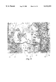
- FIG. 8 is a map of Salt Lake City and the surrounding region
- FIG. 9 is an illustration of an example of a driver's daily log as used in the present invention.
- FIG. 10 is an algorithm or instruction set for producing a precise air quality forecast.
- FIG. 1 there is shown a pictorial representation of a communication network for emission control 10 employing the teachings of the present invention. It will become evident to those skilled in the art that the advantages of the invention may be realized with wireless communication equipment as well as with a simple telephone link and other embodiments of well known telecommunications methods. Further, although a single vehicle is shown in FIG. 1 for simplicity, it will be understood that a network incorporating the invention will typically serve multiple vehicles, as well as stationary plants such as power generating facilities. Therefore, when referring to "vehicle” or "apparatus” in this detailed description, it shall be understood that these terms refer to engines on vehicles or in stationary plants located in a large geographical region, nationally or internationally.
- the network 10 comprises a network management center 12 that sends an emission control signal to a communications satellite 14 which relays the signal to a vehicle 16 having a mobile communications terminal 18 that also receives a signal from a global positioning satellite 20 as well as a time signal from the GPS or a clock within the mobile communications terminal 18.
- the mobile communications terminal 18 records received data and a time signal and then sends an emission control command 48 (FIG. 2) to an emission control device 52 (FIG. 3) on board the vehicle 16.
- the network management center 12 communicates with: a photochemical assessment monitoring station 22 to receive an ozone precursor, ozone and meteorology data set 30; a local air quality management district office 24 to receive an air quality forecast 32; an aerometric information retrieval system office 26 to receive additional air quality data 34; and a weather data office 28 to receive weather forecast data 36.
- an interpretive algorithm 42 defines the data to provide, in accordance with the invention, a more precise metro area forecast 44 which is sent to selected vehicles 16, by a service provider in a metro area of current operation, giving the time and location when an engine should be switched from a primary operating mode defined by having an ultra-low carbon dioxide exhaust fraction to an alternate operating mode defined by having an ultra-low exhaust fraction of ozone precursors in order to meet the environmental needs of each metro area, with a first objective of clean air attainment in the local metro area, and a second objective of reduced emission of global warming gases.
- the primary operating mode as described above is determined by the requirements specified in the Federal Clean Air Act and the amendment thereto.
- the algorithm 42 utilizes geographic data 38 and air quality historical data 40 to produce a precise metro area forecast 44 which is combined with selected 46 fleet vehicle addresses 45 which are appropriate recipients of an emission control command 48 communicated by the network management center 12 through the communications satellite 14 to an integrated communications terminal 18 installed on the vehicle 16.
- a vehicle electronic control system 49 includes a satellite dish 50 and a mobile communications terminal 18 which receives the emission control command 48 for further relay to an engine control module 52 for implementation by a vehicle control 58.
- the emission control command 48 can be posted on the dash display for driver actuation of a manual pollution control device (not shown).
- Emission compliance information can be stored on the vehicle data logger 56 for off-loading of emission compliance certification to a hand-held device 60 or a desk-top computer 62 etc.
- the engine data system supports interfaces common to heavy-duty vehicles, including but not limited to SAE J1708, SAE J1587, and SAE J1939.
- the emission control command 48 can be implemented on an engine equipped with an electronic control system 63 by providing a new timing command for the injector drivers 64 which activate the fuel control solenoid 66 (or, alternatively, by a piezoelectric actuator) to achieve a new beginning of injection of fuel by the injector nozzle 68, relative to the top dead center position of a piston 72 and crankshaft 74 relative to the cylinder 70 as determined by a crank position sensor 76.
- FIG. 5 shows a graphic representation of an injector driver memory 64 which stores digital data for one or more injection timing maps 81, 82, 83 having data sets that include a top dead center position 84.
- the timing map 81 shows one prior art pollution-control injector driver timing relative to the top dead center position 84 for a 49-state EPA emission compliance certification.
- the beginning of injection 88 of fuel occurs during the latter part of the compression stroke and before the top dead center position 84, although other timing positions for the beginning of injection would be obvious to a person skilled in the art.
- the end of injection 120 in this example occurs early in the power stroke and after top dead center 84, although other positions for timing for the end of injection would be obvious to those skilled in the art.
- a second timing map 82 shows typical prior art pollution-control injector driver timing relative to the top dead center position 84 for EPA very low emission compliance certification for sale in a clean air non-attainment area, such as California.
- the beginning of injection 122 of fuel occurs during the very early part of the power stroke and just after the top dead center position 84, although other timing positions for the beginning of injection would be obvious to a person skilled in the art.
- the end of injection 124 in this example occurs later in the power stroke and well after top dead center 84, although other timing positions for the end of injection would be obvious to those skilled in the art.
- This mode of operation usually has a higher emission of carbon dioxide than the first described injection timing, with a commensurate loss of economic value and an increase in emission of global warming gases.
- a third timing map 83 shows the prior art as disclosed in U.S. Pat. No. 5,265,562 and U.S. Pat. No. 5,460,128 as well as U.S. Pat. No. 5,566,650 as issued to the present inventor.
- This timing map shows the utilization of a triple injection process to limit combustion chamber pressure and also to limit combustion chamber temperature, which is a proven pollution control method for reduced creation rate of oxides of nitrogen, an ozone precursor.
- This injection timing can be utilized in metro areas with a severe clean air non-attainment status as an early introduction of advanced clean air technology for ultra-low emissions.
- the pollution-control injector driver timing for the beginning 126 of the first injection 127 of fuel occurs during the latter part of the compression stroke and just before the top dead center position 84, although other timing positions for the beginning of the first injection would be obvious to a person skilled in the art.
- the end of the first injection 128 in this example occurs later in the compression stroke and just before top dead center 84, although other timing positions for the end of the first injection would be obvious to those skilled in the art.
- the injector driver timing for the beginning 132 of the second injection 130 of fuel occurs during the very early part of the power stroke and just after the top dead center position 84, although other timing positions for the beginning of the second injection would be obvious to a person skilled in the art.
- the end of the second injection 130 in this example occurs somewhat later in the power stroke, although other timing positions for the end of the second injection would be obvious to those skilled in the art.
- the injector driver timing for the beginning 140 of the third injection 138 of fuel occurs during the later part of the power stroke after the end of the second injection 136, although another timing for the beginning of the third injection would be obvious to a person skilled in the art.
- the end 142 of the third injection 138 in this example occurs an additional time later in the power stroke, and is, in this example, approximately equal to the end of the single injection 124 of the late injection timing of the second timing map 82.
- Other timing positions for the end of the third injection would be obvious to those skilled in the art.
- the multiple injection process utilizes an early beginning 126 of the first injection 127.
- Other combinations of two or more injections, including four or more, and as many as 100 separate injections, accomplished by use of a piezoelectric actuator in place of a solenoid actuator, will be obvious to a person skilled in the art.
- One or more of the multiple injection timings will produce ultra-low emission of ozone precursors in combination with low carbon dioxide emissions, while a different set of multiple injection timings will enable engine operation with low emission of ozone precursors in combination with very low carbon dioxide emissions.
- the engine control module 52 uses one multiple injection timing map 83 for low emission operation in a clean air metro area and then, on receiving a pollution control command 48, switches to a different multiple injection timing map 83 for ultra-low emission operation in clean air non-attainment metro area 95, FIG. 7.
- This method of operation enables early attainment of compliance with the National Ambient Air Quality Standards as compared with the prior art, while providing national economic benefits as well achieving global environmental objectives.
- FIG. 6 is a map 55 of the United States showing numerous metro areas 56 classified as Ozone Non-attainment Areas by the EPA.
- a vehicle 16, first sold in Utah, and operating according to the present invention between Sacramento, Calif. and Chicago, Ill. utilizes injector timing map 83 while in the Sacramento Metro Area when that location is under a forecast of a clean air non-attainment day.
- the engine control unit 52 switches the operation of the injectors to injector timing map 81.
- the engine continues to operate according to the injector timing map 81, achieving significant reduction in emission of carbon dioxide and an economic a benefit from reduced fuel use.
- a similar vehicle 16 first sold in California would operate in with injector timing map 82 when driving in California on a clean air day.
- injector timing map 83 When an emission control command 48 is received by this vehicle the operator switches to injector timing map 83 while in the Metro Area under a forecast of a clean air non-attainment day.
- FIG. 7 is a map 88 of Utah, showing the Salt Lake City metro area 90, two longitude lines 92, and two latitude lines 94 that define a control zone 95 where ultra-low emission compliance rewards engine operation according to injector timing map 83 on a day that has a forecast for clean air non-attainment in the Salt Lake City metro area 90.
- a vehicle operating according to the present invention has a pollution control command 48 stored in the memory of the engine control unit 52 as a result of the daily air quality forecast.
- a command is sent to the engine control unit 52 causing the microcontroller 53 to switch to injector timing map 83, with said mode of operation continuing until a new location signal is received that indicates departure from the control zone 95.
- another exemplary method of putting the invention into practice utilizes a standard road map 89 of the Salt Lake City area in conjunction with a pollution control command 48 communicated by telephone message, facsimile message, pager message or other simple communication means.
- the mode-switching command 48 is accomplished by a device as simple as a mechanical or electronic control to actuate an exhaust gas recirculation valve, which is readily understood and implemented by a person skilled in the art.
- a compliance recording means 102 can be as simple as a standard Department of Transportation approved Driver's Daily Log, with a time-based pollution control command 48 shown to be acted on by the markings 105 at 6 AM on the Driver's Daily Log and a location-based pollution control command 48 recorded 106 when the vehicle exits the control zone 95.
- the remarks area 107 of the Driver's Daily Log is shown to contain notations by the driver confirming the beginning 108 and the end 109 of the ultra-low emission engine operation.
- the invention utilizes an apparatus comprising a means for producing energy by the combustion of fuel, the energy producing means is enabled by an air breathing and combustion products exhausting process such as in an internal combustion engine, and is further enabled wherein said process is adjustable between at least two distinct modes of operation, primarily by dynamically adjusting engine timing; one said mode resulting in low emission of carbon dioxide and ultra-low emission of ozone precursors, ozone and other atmospheric pollutants, and another said mode resulting in ultra-low emission of carbon dioxide and low emission of ozone precursors, ozone and other atmospheric pollutants; the energy producing means engaged for control by an engine control module providing a switching means enabled for operating the energy producing means in any one of the at least two, but potentially more, distinct modes of operation; the apparatus further comprising a time and location recording means enabled for automatically recording time of day and geographic location of the mobile apparatus at each change of said mode.
- the engine control module is enabled through an algorithm, for control by a wave energy signal of remote origin and in accordance with a pollution control protocol adapted in accordance with an air quality forecast.
- the method of the present invention is enabled by an interpretive algorithm enablement in creating a precise metro area forecast and further enabled by a definitive time and location of said mode switching; said algorithm comprising: receiving an air quality forecast of peak ozone value (POV fcst ); determining the pollution standard index number (PSI) corresponding to the POV fcst ; transmitting the remote wave energy comprising data based upon the PSI to the apparatus; implementing a primary appropriate operating mode if PSI ⁇ X; implementing an alternate appropriate operating mode if PSI>X; repeating the algorithm at each successive time increments; wherein "X" corresponds to a number estimated to provide the highest probability of operating in ultra-low emission mode when necessary.
- POV fcst peak ozone value
- PSI pollution standard index number
Abstract
Description
Claims (14)
Priority Applications (1)
| Application Number | Priority Date | Filing Date | Title |
|---|---|---|---|
| US09/264,488 US6112151A (en) | 1999-03-08 | 1999-03-08 | Adaptive emission control with communication network |
Applications Claiming Priority (1)
| Application Number | Priority Date | Filing Date | Title |
|---|---|---|---|
| US09/264,488 US6112151A (en) | 1999-03-08 | 1999-03-08 | Adaptive emission control with communication network |
Publications (1)
| Publication Number | Publication Date |
|---|---|
| US6112151A true US6112151A (en) | 2000-08-29 |
Family
ID=23006291
Family Applications (1)
| Application Number | Title | Priority Date | Filing Date |
|---|---|---|---|
| US09/264,488 Expired - Fee Related US6112151A (en) | 1999-03-08 | 1999-03-08 | Adaptive emission control with communication network |
Country Status (1)
| Country | Link |
|---|---|
| US (1) | US6112151A (en) |
Cited By (69)
| Publication number | Priority date | Publication date | Assignee | Title |
|---|---|---|---|---|
| US6260539B1 (en) * | 1993-12-28 | 2001-07-17 | Hitachi, Ltd. | Control apparatus and a control method for a vehicle |
| US20020073000A1 (en) * | 2000-05-05 | 2002-06-13 | Mike Sage | System and method for implementing a wireless network in a service center for generating a repair order |
| US6411888B1 (en) * | 2000-06-12 | 2002-06-25 | Detroit Diesel Corporation | Gauging driving efficiency |
| US20020189564A1 (en) * | 2001-01-31 | 2002-12-19 | Biess Lawrence J. | Locomotive and auxiliary power unit engine controller |
| US6636798B2 (en) | 2001-01-31 | 2003-10-21 | Csxt Intellectual Properties Corporation | Locomotive emission reduction kit and method of earning emission credits |
| US6665606B2 (en) * | 2001-02-20 | 2003-12-16 | Cummins, Inc. | Distributed engine processing system |
| US20040035618A1 (en) * | 2000-09-27 | 2004-02-26 | Georg Grassl | Drivetrain controller for a motor vehicle with at least two power units and a gear-box |
| US20040084232A1 (en) * | 2000-12-28 | 2004-05-06 | Denso Corporation | Vehicular power supply apparatus and engine-drive-regulation supporting apparatus |
| WO2004048911A2 (en) * | 2002-11-26 | 2004-06-10 | Agcert International, Llc | System and method for tracking environmental emission reductions |
| US20040128058A1 (en) * | 2002-12-30 | 2004-07-01 | Andres David J. | Engine control strategies |
| WO2005052344A1 (en) * | 2003-11-27 | 2005-06-09 | Siemens Aktiengesellschaft | Method and device for optimising the operation of an internal combustion engine embodied with a direct fuel injection system |
| US20050120904A1 (en) * | 2002-02-28 | 2005-06-09 | Ajith Kumar | Configurable locomotive |
| US20050149248A1 (en) * | 2004-01-07 | 2005-07-07 | Polen Jerry V. | Location-sensitive engine emission control system and method |
| US20050192724A1 (en) * | 2004-02-26 | 2005-09-01 | Jason Hendry | Method and apparatus for importing weather data from source external to vehicle |
| US6945207B2 (en) | 2001-01-31 | 2005-09-20 | Csx Transportation, Inc. | System and method for supplying auxiliary power to a large diesel engine |
| US20060041370A1 (en) * | 2004-08-19 | 2006-02-23 | General Motors Corporation | Method and system for providing location specific fuel emissions compliance for a mobile vehicle |
| US20060195334A1 (en) * | 2004-11-17 | 2006-08-31 | Reeb Shayne A | Integrated environmental emission reduction data management system and method |
| US20060243788A1 (en) * | 2005-04-04 | 2006-11-02 | David Waco | Method and apparatus for wireless PC tablet presentation process |
| US20070090937A1 (en) * | 2005-10-21 | 2007-04-26 | Stabler Francis R | Method for alerting a vehicle user to refuel prior to exceeding a remaining driving distance |
| US20070143007A1 (en) * | 2005-12-20 | 2007-06-21 | Caterpillar Inc. | Exhaust control system implementing fuel quality detection |
| US20070175459A1 (en) * | 2006-02-02 | 2007-08-02 | Williams Rodger K | Fuel control system and associated method |
| US20070192012A1 (en) * | 2006-02-14 | 2007-08-16 | Detroit Diesel Corporation | Method and system of enhanced vehicle road speed limiting |
| US20070240687A1 (en) * | 2006-04-10 | 2007-10-18 | Payne Edward A | Fuel control system and associated method |
| US20070277794A1 (en) * | 2006-05-21 | 2007-12-06 | Payne Edward A | Alternate Fuel Storage System and Method |
| US20080109122A1 (en) * | 2005-11-30 | 2008-05-08 | Ferguson Alan L | Work machine control using off-board information |
| US20080262701A1 (en) * | 2007-04-18 | 2008-10-23 | Williams Rodger K | Alternate fuel blending system and associated method |
| US20090171549A1 (en) * | 2007-12-31 | 2009-07-02 | Hyde Roderick A | Condition-sensitive exhaust control |
| US20090171555A1 (en) * | 2007-12-31 | 2009-07-02 | Searete Llc, A Limited Liability Corporation Of The State Of Delaware | System and method for remotely modifying vehicle operations |
| US20090171547A1 (en) * | 2007-12-31 | 2009-07-02 | Hyde Roderick A | Traffic-sensitive engine control |
| US20090171548A1 (en) * | 2007-12-31 | 2009-07-02 | Searete Llc, A Limited Liability Corporation Of The State Of Delaware | System and method for operating a vehicle |
| WO2009088437A1 (en) * | 2007-12-31 | 2009-07-16 | Searete Llc | System and method for remotely modifying vehicle operations |
| US20090240388A1 (en) * | 2008-03-19 | 2009-09-24 | Zero Emission Systems, Inc. | Data acquisition for operation of a vehicle |
| US20100082225A1 (en) * | 2008-09-30 | 2010-04-01 | International Business Machines Corporation | System and process for adapting vehicle emissions to surrounding pollution level: the "green compliance module" |
| US20100088016A1 (en) * | 2008-10-02 | 2010-04-08 | International Business Machines Corporation | Environmentally aware travel routing |
| US20100187030A1 (en) * | 2009-01-26 | 2010-07-29 | Chris Conway Gearhart | Energy Management System and Method for Hybrid Electric Vehicles |
| US20110029182A1 (en) * | 2009-07-29 | 2011-02-03 | Searete Llc, A Limited Liability Corporation Of The State Of Delaware | Vehicle system for varied compliance benefits |
| US20110029192A1 (en) * | 2009-07-29 | 2011-02-03 | Searete Llc | Selective implementation of an optional vehicle mode |
| US20110029171A1 (en) * | 2009-07-29 | 2011-02-03 | Searete Llc, A Limited Liability Corporation Of The State Of Delaware | Selective control system for vehicle operating parameters |
| US20110029358A1 (en) * | 2009-07-29 | 2011-02-03 | Searete Llc, A Limited Liability Corporation Of The State Of Delaware | Promotional incentives based on hybrid vehicle qualification |
| US20110029188A1 (en) * | 2009-07-29 | 2011-02-03 | Searete Llc, A Limited Liability Corporation Of The State Of Delaware | Remote processing of selected vehicle operating parameters |
| US20110029181A1 (en) * | 2009-07-29 | 2011-02-03 | Searete Llc., A Limited Liability Corporation Of The State Of Delaware | Selective control of an optional vehicle mode |
| US20110029356A1 (en) * | 2009-07-29 | 2011-02-03 | Searete Llc, A Limited Liability Corporation Of The State Of Delaware | Selective control of an optional vehicle mode |
| US20110029357A1 (en) * | 2009-07-29 | 2011-02-03 | Searete Llc, A Limited Liability Corporation Of The State Of Delaware | Promotional correlation with selective vehicle modes |
| US20110029170A1 (en) * | 2009-07-29 | 2011-02-03 | Searete LLC, a limited liability corporation on the State of Delaware | System for selective vehicle operation modes |
| US20110029189A1 (en) * | 2009-07-29 | 2011-02-03 | Searete Llc, A Limited Liability Corporation Of The State Of Delaware | Promotional correlation with selective vehicle modes |
| US20110056185A1 (en) * | 2009-09-03 | 2011-03-10 | Clean Emissions Technologies, Inc. | Vehicle Reduced Emission Deployment |
| US20110077805A1 (en) * | 2009-09-29 | 2011-03-31 | Searete Llc, A Limited Liability Corporation Of The State Of Delaware | Selective implementation of an optional vehicle mode |
| US20110077807A1 (en) * | 2009-07-29 | 2011-03-31 | Searete Llc, A Limited Liability Corporation Of The State Of Delaware | Vehicle system for varied compliance benefits |
| US20110077806A1 (en) * | 2009-09-29 | 2011-03-31 | Searete Llc, A Limited Liability Corporation Of The State Of Delaware | Selective implementation of an optional vehicle mode |
| US20110087399A1 (en) * | 2009-07-29 | 2011-04-14 | Searete Llc, A Limited Corporation Of The State Of Delaware | Promotional correlation with selective vehicle modes |
| AU2005267004B2 (en) * | 2004-07-23 | 2012-03-15 | Ge Global Sourcing Llc | System and method for managing emissions from mobile vehicles |
| US20130124033A1 (en) * | 2011-11-10 | 2013-05-16 | Horiba, Ltd. | Test System |
| US8509991B2 (en) | 2010-03-31 | 2013-08-13 | Honda Motor Co., Ltd. | Method of estimating an air quality condition by a motor vehicle |
| US8571791B2 (en) | 2009-07-29 | 2013-10-29 | Searete Llc | Remote processing of selected vehicle operating parameters |
| US9123049B2 (en) | 2009-07-29 | 2015-09-01 | The Invention Science Fund I, Llc | Promotional correlation with selective vehicle modes |
| CN104884305A (en) * | 2012-12-27 | 2015-09-02 | 冷王公司 | Geographic specific controlling of a transport refrigeration system |
| US9151232B2 (en) | 2001-03-27 | 2015-10-06 | General Electric Company | Control system and method |
| CN105026740A (en) * | 2012-11-28 | 2015-11-04 | 冷王公司 | Methods and systems to control an engine of a transport refrigeration unit |
| US9243581B2 (en) | 2010-09-24 | 2016-01-26 | Cummins Inc. | Engine control system and method based on fuel quality |
| US9457792B2 (en) | 2006-03-14 | 2016-10-04 | Clean Emissions Technologies, Inc. | Retrofitting a vehicle drive train |
| US20170127220A1 (en) * | 2015-11-04 | 2017-05-04 | Scepter Incorporated | Atmospheric sensor network and analytical information system related thereto |
| US9758146B2 (en) | 2008-04-01 | 2017-09-12 | Clean Emissions Technologies, Inc. | Dual mode clutch pedal for vehicle |
| US20180045095A1 (en) * | 2016-08-09 | 2018-02-15 | Caterpillar Inc. | Emission control with switchability between emission standards |
| US9919715B2 (en) * | 2016-04-30 | 2018-03-20 | Ford Global Technologies, Llc | Vehicle mode scheduling with learned user preferences |
| US9964054B2 (en) | 2014-10-08 | 2018-05-08 | Immixt, LLC | Alternate fuel blending systems and associated methods |
| CN111779580A (en) * | 2019-04-04 | 2020-10-16 | 现代自动车株式会社 | Control system and method for controlling exhaust emissions of a motor vehicle |
| US11085383B2 (en) * | 2017-03-08 | 2021-08-10 | Bayerische Motoren Werke Aktiengesellschaft | Control unit for adapting the emission of a vehicle |
| US11204271B2 (en) | 2015-12-08 | 2021-12-21 | Gilbarco Inc. | Systems and methods for alternative fuel life-cycle tracking and validation |
| US20220055611A1 (en) * | 2020-08-20 | 2022-02-24 | Toyota Jidosha Kabushiki Kaisha | Engine starter |
Citations (10)
| Publication number | Priority date | Publication date | Assignee | Title |
|---|---|---|---|---|
| US4883034A (en) * | 1987-07-31 | 1989-11-28 | Mazda Motor Corporation | Engine idling speed control system |
| US5315295A (en) * | 1991-01-18 | 1994-05-24 | Mazda Motor Corporation | Vehicle speed control system |
| US5446665A (en) * | 1993-03-18 | 1995-08-29 | John B. Adrain | Automotive multiple memory selector apparatus |
| US5638790A (en) * | 1993-12-28 | 1997-06-17 | Hitachi, Ltd. | Control apparatus and a control method for a vehicle |
| US5769051A (en) * | 1996-05-29 | 1998-06-23 | Bayron; Harry | Data input interface for power and speed controller |
| US5983156A (en) * | 1997-09-03 | 1999-11-09 | Cummins Engine Company | System for controlling engine fueling according to vehicle location |
| US5995879A (en) * | 1997-01-24 | 1999-11-30 | Caterpillar Inc. | Engine command selector and method of operating same |
| US5999876A (en) * | 1998-04-01 | 1999-12-07 | Cummins Engine Company, Inc. | Method and system for communication with an engine control module in sleep mode |
| US6012013A (en) * | 1995-03-31 | 2000-01-04 | Trimble Navigation Limited | Vehicle position reporting in user defined uni-dimensional coordinate system |
| US6021371A (en) * | 1997-04-16 | 2000-02-01 | Trimble Navigation Limited | Communication and navigation system incorporating position determination |
-
1999
- 1999-03-08 US US09/264,488 patent/US6112151A/en not_active Expired - Fee Related
Patent Citations (10)
| Publication number | Priority date | Publication date | Assignee | Title |
|---|---|---|---|---|
| US4883034A (en) * | 1987-07-31 | 1989-11-28 | Mazda Motor Corporation | Engine idling speed control system |
| US5315295A (en) * | 1991-01-18 | 1994-05-24 | Mazda Motor Corporation | Vehicle speed control system |
| US5446665A (en) * | 1993-03-18 | 1995-08-29 | John B. Adrain | Automotive multiple memory selector apparatus |
| US5638790A (en) * | 1993-12-28 | 1997-06-17 | Hitachi, Ltd. | Control apparatus and a control method for a vehicle |
| US6012013A (en) * | 1995-03-31 | 2000-01-04 | Trimble Navigation Limited | Vehicle position reporting in user defined uni-dimensional coordinate system |
| US5769051A (en) * | 1996-05-29 | 1998-06-23 | Bayron; Harry | Data input interface for power and speed controller |
| US5995879A (en) * | 1997-01-24 | 1999-11-30 | Caterpillar Inc. | Engine command selector and method of operating same |
| US6021371A (en) * | 1997-04-16 | 2000-02-01 | Trimble Navigation Limited | Communication and navigation system incorporating position determination |
| US5983156A (en) * | 1997-09-03 | 1999-11-09 | Cummins Engine Company | System for controlling engine fueling according to vehicle location |
| US5999876A (en) * | 1998-04-01 | 1999-12-07 | Cummins Engine Company, Inc. | Method and system for communication with an engine control module in sleep mode |
Cited By (132)
| Publication number | Priority date | Publication date | Assignee | Title |
|---|---|---|---|---|
| US6260539B1 (en) * | 1993-12-28 | 2001-07-17 | Hitachi, Ltd. | Control apparatus and a control method for a vehicle |
| US20020073000A1 (en) * | 2000-05-05 | 2002-06-13 | Mike Sage | System and method for implementing a wireless network in a service center for generating a repair order |
| US6411888B1 (en) * | 2000-06-12 | 2002-06-25 | Detroit Diesel Corporation | Gauging driving efficiency |
| US7017692B2 (en) * | 2000-09-27 | 2006-03-28 | Siemens Aktiengesellschaft | Drivetrain controller for a motor vehicle with at least two power units and a gear-box |
| US20040035618A1 (en) * | 2000-09-27 | 2004-02-26 | Georg Grassl | Drivetrain controller for a motor vehicle with at least two power units and a gear-box |
| US20040084232A1 (en) * | 2000-12-28 | 2004-05-06 | Denso Corporation | Vehicular power supply apparatus and engine-drive-regulation supporting apparatus |
| US6986398B2 (en) * | 2000-12-28 | 2006-01-17 | Denso Corporation | Vehicular power supply apparatus and engine-drive-regulation supporting apparatus |
| US20020189564A1 (en) * | 2001-01-31 | 2002-12-19 | Biess Lawrence J. | Locomotive and auxiliary power unit engine controller |
| US6636798B2 (en) | 2001-01-31 | 2003-10-21 | Csxt Intellectual Properties Corporation | Locomotive emission reduction kit and method of earning emission credits |
| US6945207B2 (en) | 2001-01-31 | 2005-09-20 | Csx Transportation, Inc. | System and method for supplying auxiliary power to a large diesel engine |
| US6928972B2 (en) | 2001-01-31 | 2005-08-16 | Csxt Intellectual Properties Corporation | Locomotive and auxiliary power unit engine controller |
| US6665606B2 (en) * | 2001-02-20 | 2003-12-16 | Cummins, Inc. | Distributed engine processing system |
| US9151232B2 (en) | 2001-03-27 | 2015-10-06 | General Electric Company | Control system and method |
| US7302895B2 (en) | 2002-02-28 | 2007-12-04 | General Electric Company | Configurable locomotive |
| US20050120904A1 (en) * | 2002-02-28 | 2005-06-09 | Ajith Kumar | Configurable locomotive |
| US20070265897A1 (en) * | 2002-11-26 | 2007-11-15 | Mcmorris John A Iii | System and Method of Creating, Aggregating, and Transferring Environmental Emission Reductions |
| WO2004048911A3 (en) * | 2002-11-26 | 2005-02-17 | Agcert International Llc | System and method for tracking environmental emission reductions |
| US20050021495A1 (en) * | 2002-11-26 | 2005-01-27 | Mcmorris John A. | System and method for tracking environmental emission reductions |
| US20040230443A1 (en) * | 2002-11-26 | 2004-11-18 | Mcmorris John A. | System and method of creating, aggregating, and transferring environmental emisssion reductions |
| WO2004048911A2 (en) * | 2002-11-26 | 2004-06-10 | Agcert International, Llc | System and method for tracking environmental emission reductions |
| US6965826B2 (en) | 2002-12-30 | 2005-11-15 | Caterpillar Inc | Engine control strategies |
| WO2004061284A1 (en) * | 2002-12-30 | 2004-07-22 | Caterpillar Inc. | Engine control strategies |
| US20040128058A1 (en) * | 2002-12-30 | 2004-07-01 | Andres David J. | Engine control strategies |
| WO2005052344A1 (en) * | 2003-11-27 | 2005-06-09 | Siemens Aktiengesellschaft | Method and device for optimising the operation of an internal combustion engine embodied with a direct fuel injection system |
| US20050149248A1 (en) * | 2004-01-07 | 2005-07-07 | Polen Jerry V. | Location-sensitive engine emission control system and method |
| US20050192724A1 (en) * | 2004-02-26 | 2005-09-01 | Jason Hendry | Method and apparatus for importing weather data from source external to vehicle |
| AU2005267004B2 (en) * | 2004-07-23 | 2012-03-15 | Ge Global Sourcing Llc | System and method for managing emissions from mobile vehicles |
| US7062371B2 (en) * | 2004-08-19 | 2006-06-13 | General Motors Corporation | Method and system for providing location specific fuel emissions compliance for a mobile vehicle |
| US20060041370A1 (en) * | 2004-08-19 | 2006-02-23 | General Motors Corporation | Method and system for providing location specific fuel emissions compliance for a mobile vehicle |
| US20060195334A1 (en) * | 2004-11-17 | 2006-08-31 | Reeb Shayne A | Integrated environmental emission reduction data management system and method |
| US20060243788A1 (en) * | 2005-04-04 | 2006-11-02 | David Waco | Method and apparatus for wireless PC tablet presentation process |
| US20070090937A1 (en) * | 2005-10-21 | 2007-04-26 | Stabler Francis R | Method for alerting a vehicle user to refuel prior to exceeding a remaining driving distance |
| US20080109122A1 (en) * | 2005-11-30 | 2008-05-08 | Ferguson Alan L | Work machine control using off-board information |
| US7522994B2 (en) * | 2005-12-20 | 2009-04-21 | Caterpillar Inc. | Exhaust control system implementing fuel quality detection |
| US20070143007A1 (en) * | 2005-12-20 | 2007-06-21 | Caterpillar Inc. | Exhaust control system implementing fuel quality detection |
| US20110224884A1 (en) * | 2006-02-02 | 2011-09-15 | Williams Rodger K | Fuel control system and associated method |
| US9458772B2 (en) | 2006-02-02 | 2016-10-04 | Immixt, LLC | Fuel control system and associated method |
| US8006677B2 (en) | 2006-02-02 | 2011-08-30 | Immixt, LLC | Fuel control system and associated method |
| US20070175459A1 (en) * | 2006-02-02 | 2007-08-02 | Williams Rodger K | Fuel control system and associated method |
| US8726893B2 (en) | 2006-02-02 | 2014-05-20 | Immixt, LLC | Fuel control system and associated method |
| US20070192012A1 (en) * | 2006-02-14 | 2007-08-16 | Detroit Diesel Corporation | Method and system of enhanced vehicle road speed limiting |
| US9457792B2 (en) | 2006-03-14 | 2016-10-04 | Clean Emissions Technologies, Inc. | Retrofitting a vehicle drive train |
| US8485165B2 (en) | 2006-04-10 | 2013-07-16 | Immixt, LLC | Fuel control system and associated method |
| US20070240687A1 (en) * | 2006-04-10 | 2007-10-18 | Payne Edward A | Fuel control system and associated method |
| US7721720B2 (en) | 2006-04-10 | 2010-05-25 | Payne Edward A | Fuel control system and associated method |
| US20100161200A1 (en) * | 2006-04-10 | 2010-06-24 | Payne Edward A | Fuel control system and associated method |
| US8893691B2 (en) | 2006-04-10 | 2014-11-25 | Immixt, LLC | Fuel control system and associated method |
| US8640678B2 (en) | 2006-05-21 | 2014-02-04 | Immixt, LLC | Alternate fuel storage system and method |
| US8256401B2 (en) | 2006-05-21 | 2012-09-04 | Immixt, LLC | Alternate fuel storage system and method |
| US20070277794A1 (en) * | 2006-05-21 | 2007-12-06 | Payne Edward A | Alternate Fuel Storage System and Method |
| US7913664B2 (en) | 2007-04-18 | 2011-03-29 | Williams Rodger K | Alternate fuel blending system and associated method |
| US20110029219A1 (en) * | 2007-04-18 | 2011-02-03 | Williams Rodger K | Alternate fuel blending system and associated method |
| US7841317B2 (en) | 2007-04-18 | 2010-11-30 | Williams Rodger K | Alternate fuel blending system and associated method |
| US20080262701A1 (en) * | 2007-04-18 | 2008-10-23 | Williams Rodger K | Alternate fuel blending system and associated method |
| WO2009088437A1 (en) * | 2007-12-31 | 2009-07-16 | Searete Llc | System and method for remotely modifying vehicle operations |
| US8335636B2 (en) * | 2007-12-31 | 2012-12-18 | The Invention Science Fund I, Llc | System and method for remotely modifying vehicle operations |
| US20090171549A1 (en) * | 2007-12-31 | 2009-07-02 | Hyde Roderick A | Condition-sensitive exhaust control |
| US7957892B2 (en) | 2007-12-31 | 2011-06-07 | The Invention Science Fund I, Llc | Condition-sensitive exhaust control |
| US20090171555A1 (en) * | 2007-12-31 | 2009-07-02 | Searete Llc, A Limited Liability Corporation Of The State Of Delaware | System and method for remotely modifying vehicle operations |
| US20090171547A1 (en) * | 2007-12-31 | 2009-07-02 | Hyde Roderick A | Traffic-sensitive engine control |
| US8335635B2 (en) * | 2007-12-31 | 2012-12-18 | The Invention Science Fund I, Llc | System and method for operating a vehicle |
| US8386148B2 (en) | 2007-12-31 | 2013-02-26 | The Invention Science Fund I, Llc | Traffic-sensitive engine control |
| US20090171548A1 (en) * | 2007-12-31 | 2009-07-02 | Searete Llc, A Limited Liability Corporation Of The State Of Delaware | System and method for operating a vehicle |
| US20090240388A1 (en) * | 2008-03-19 | 2009-09-24 | Zero Emission Systems, Inc. | Data acquisition for operation of a vehicle |
| US9707861B2 (en) * | 2008-03-19 | 2017-07-18 | Clean Emissions Technologies, Inc. | Data acquisition for operation of a vehicle |
| US9758146B2 (en) | 2008-04-01 | 2017-09-12 | Clean Emissions Technologies, Inc. | Dual mode clutch pedal for vehicle |
| US20100082225A1 (en) * | 2008-09-30 | 2010-04-01 | International Business Machines Corporation | System and process for adapting vehicle emissions to surrounding pollution level: the "green compliance module" |
| US20100088016A1 (en) * | 2008-10-02 | 2010-04-08 | International Business Machines Corporation | Environmentally aware travel routing |
| US8151916B2 (en) | 2009-01-26 | 2012-04-10 | Ford Global Technologies, Llc | Energy management system and method for hybrid electric vehicles |
| US20100187030A1 (en) * | 2009-01-26 | 2010-07-29 | Chris Conway Gearhart | Energy Management System and Method for Hybrid Electric Vehicles |
| US9123049B2 (en) | 2009-07-29 | 2015-09-01 | The Invention Science Fund I, Llc | Promotional correlation with selective vehicle modes |
| US9073554B2 (en) * | 2009-07-29 | 2015-07-07 | The Invention Science Fund I, Llc | Systems and methods for providing selective control of a vehicle operational mode |
| US20110087399A1 (en) * | 2009-07-29 | 2011-04-14 | Searete Llc, A Limited Corporation Of The State Of Delaware | Promotional correlation with selective vehicle modes |
| US20110029171A1 (en) * | 2009-07-29 | 2011-02-03 | Searete Llc, A Limited Liability Corporation Of The State Of Delaware | Selective control system for vehicle operating parameters |
| US8301320B2 (en) | 2009-07-29 | 2012-10-30 | The Invention Science Fund I, Llc | Vehicle system for varied compliance benefits |
| US8326485B2 (en) | 2009-07-29 | 2012-12-04 | The Invention Science Fund I, Llc | Selective control system for vehicle operating parameters |
| US8332099B2 (en) | 2009-07-29 | 2012-12-11 | The Invention Science Fund I, Llc | Selective implementation of an optional vehicle mode |
| US20110077807A1 (en) * | 2009-07-29 | 2011-03-31 | Searete Llc, A Limited Liability Corporation Of The State Of Delaware | Vehicle system for varied compliance benefits |
| US20110029358A1 (en) * | 2009-07-29 | 2011-02-03 | Searete Llc, A Limited Liability Corporation Of The State Of Delaware | Promotional incentives based on hybrid vehicle qualification |
| US8352107B2 (en) | 2009-07-29 | 2013-01-08 | The Invention Science Fund I, Llc | Vehicle system for varied compliance benefits |
| US20110029192A1 (en) * | 2009-07-29 | 2011-02-03 | Searete Llc | Selective implementation of an optional vehicle mode |
| US8392101B2 (en) | 2009-07-29 | 2013-03-05 | The Invention Science Fund I Llc | Promotional correlation with selective vehicle modes |
| US8396624B2 (en) | 2009-07-29 | 2013-03-12 | The Invention Science Fund I, Llc | Remote processing of selected vehicle operating parameters |
| US8412454B2 (en) * | 2009-07-29 | 2013-04-02 | The Invention Science Fund I, Llc | Selective control of an optional vehicle mode |
| US20110029182A1 (en) * | 2009-07-29 | 2011-02-03 | Searete Llc, A Limited Liability Corporation Of The State Of Delaware | Vehicle system for varied compliance benefits |
| US8452532B2 (en) * | 2009-07-29 | 2013-05-28 | The Invention Science Fund I, Llc | Selective control of an optional vehicle mode |
| US8457873B2 (en) | 2009-07-29 | 2013-06-04 | The Invention Science Fund I, Llc | Promotional incentives based on hybrid vehicle qualification |
| US20110029189A1 (en) * | 2009-07-29 | 2011-02-03 | Searete Llc, A Limited Liability Corporation Of The State Of Delaware | Promotional correlation with selective vehicle modes |
| US20110029188A1 (en) * | 2009-07-29 | 2011-02-03 | Searete Llc, A Limited Liability Corporation Of The State Of Delaware | Remote processing of selected vehicle operating parameters |
| US8571731B2 (en) | 2009-07-29 | 2013-10-29 | Searete Llc | Hybrid vehicle qualification for preferential result |
| US8571791B2 (en) | 2009-07-29 | 2013-10-29 | Searete Llc | Remote processing of selected vehicle operating parameters |
| US8571740B2 (en) | 2009-07-29 | 2013-10-29 | Searete Llc | Vehicle system for varied compliance benefits |
| US20110029170A1 (en) * | 2009-07-29 | 2011-02-03 | Searete LLC, a limited liability corporation on the State of Delaware | System for selective vehicle operation modes |
| US20110029357A1 (en) * | 2009-07-29 | 2011-02-03 | Searete Llc, A Limited Liability Corporation Of The State Of Delaware | Promotional correlation with selective vehicle modes |
| US20110029181A1 (en) * | 2009-07-29 | 2011-02-03 | Searete Llc., A Limited Liability Corporation Of The State Of Delaware | Selective control of an optional vehicle mode |
| US9008956B2 (en) | 2009-07-29 | 2015-04-14 | The Invention Science Fund I, Llc | Promotional correlation with selective vehicle modes |
| US20110029356A1 (en) * | 2009-07-29 | 2011-02-03 | Searete Llc, A Limited Liability Corporation Of The State Of Delaware | Selective control of an optional vehicle mode |
| US9631528B2 (en) | 2009-09-03 | 2017-04-25 | Clean Emissions Technologies, Inc. | Vehicle reduced emission deployment |
| US20110056185A1 (en) * | 2009-09-03 | 2011-03-10 | Clean Emissions Technologies, Inc. | Vehicle Reduced Emission Deployment |
| US8751059B2 (en) | 2009-09-29 | 2014-06-10 | The Invention Science Fund I, Llc | Selective implementation of an optional vehicle mode |
| US8751058B2 (en) | 2009-09-29 | 2014-06-10 | The Invention Science Fund I, Llc | Selective implementation of an optional vehicle mode |
| US20110077805A1 (en) * | 2009-09-29 | 2011-03-31 | Searete Llc, A Limited Liability Corporation Of The State Of Delaware | Selective implementation of an optional vehicle mode |
| US20110077806A1 (en) * | 2009-09-29 | 2011-03-31 | Searete Llc, A Limited Liability Corporation Of The State Of Delaware | Selective implementation of an optional vehicle mode |
| WO2011062620A1 (en) * | 2009-11-20 | 2011-05-26 | Searete Llc | System for selective vehicle operation modes |
| US8509991B2 (en) | 2010-03-31 | 2013-08-13 | Honda Motor Co., Ltd. | Method of estimating an air quality condition by a motor vehicle |
| US9938915B2 (en) | 2010-09-24 | 2018-04-10 | Cummins Inc. | Engine control system and method based on fuel quality |
| US11280283B2 (en) | 2010-09-24 | 2022-03-22 | Cummins Intellectual Property, Inc. | Engine control system and method based on fuel quality |
| US9243581B2 (en) | 2010-09-24 | 2016-01-26 | Cummins Inc. | Engine control system and method based on fuel quality |
| US9140675B2 (en) * | 2011-11-10 | 2015-09-22 | Horiba, Ltd. | Test system |
| US20130124033A1 (en) * | 2011-11-10 | 2013-05-16 | Horiba, Ltd. | Test System |
| CN105026740A (en) * | 2012-11-28 | 2015-11-04 | 冷王公司 | Methods and systems to control an engine of a transport refrigeration unit |
| US10682897B2 (en) | 2012-11-28 | 2020-06-16 | Thermo King Corporation | Methods and systems to control an engine of a transport refrigeration unit |
| EP2925989A4 (en) * | 2012-11-28 | 2016-10-12 | Thermo King Corp | Methods and systems to control an engine of a transport refrigeration unit |
| US20150338858A1 (en) * | 2012-12-27 | 2015-11-26 | Thermo King Corporation | Geographic specific controlling of a transport refrigeration system |
| CN104884305A (en) * | 2012-12-27 | 2015-09-02 | 冷王公司 | Geographic specific controlling of a transport refrigeration system |
| US10353410B2 (en) * | 2012-12-27 | 2019-07-16 | Thermo King Corporation | Geographic specific controlling of a transport refrigeration system |
| US10316769B2 (en) | 2014-10-08 | 2019-06-11 | Immixt, LLC | Alternate fueling systems and associated methods |
| US9964054B2 (en) | 2014-10-08 | 2018-05-08 | Immixt, LLC | Alternate fuel blending systems and associated methods |
| US11829691B2 (en) | 2015-11-04 | 2023-11-28 | Scepter Incorporated | Atmospheric sensor network and analytical information system related thereto |
| EP3374805A4 (en) * | 2015-11-04 | 2019-05-29 | Scepter Incorporated | Atmospheric sensor network and analytical information system related thereto |
| US9959374B2 (en) * | 2015-11-04 | 2018-05-01 | Scepter Incorporated | Atmospheric sensor network and analytical information system related thereto |
| US10642943B2 (en) | 2015-11-04 | 2020-05-05 | Scepter Incorporated | Atmospheric sensor network and analytical information system related thereto |
| US20170127220A1 (en) * | 2015-11-04 | 2017-05-04 | Scepter Incorporated | Atmospheric sensor network and analytical information system related thereto |
| US11281822B2 (en) | 2015-11-04 | 2022-03-22 | Scepter Incorporated | Atmospheric sensor network and analytical information system related thereto |
| US11204271B2 (en) | 2015-12-08 | 2021-12-21 | Gilbarco Inc. | Systems and methods for alternative fuel life-cycle tracking and validation |
| US9919715B2 (en) * | 2016-04-30 | 2018-03-20 | Ford Global Technologies, Llc | Vehicle mode scheduling with learned user preferences |
| US20180045095A1 (en) * | 2016-08-09 | 2018-02-15 | Caterpillar Inc. | Emission control with switchability between emission standards |
| US11085383B2 (en) * | 2017-03-08 | 2021-08-10 | Bayerische Motoren Werke Aktiengesellschaft | Control unit for adapting the emission of a vehicle |
| US10975783B2 (en) * | 2019-04-04 | 2021-04-13 | Hyundai Motor Company | Control system and method for controlling exhaust gas emission of a motor vehicle |
| CN111779580A (en) * | 2019-04-04 | 2020-10-16 | 现代自动车株式会社 | Control system and method for controlling exhaust emissions of a motor vehicle |
| CN111779580B (en) * | 2019-04-04 | 2023-01-20 | 现代自动车株式会社 | Control system and method for controlling exhaust emissions of a motor vehicle |
| US20220055611A1 (en) * | 2020-08-20 | 2022-02-24 | Toyota Jidosha Kabushiki Kaisha | Engine starter |
Similar Documents
| Publication | Publication Date | Title |
|---|---|---|
| US6112151A (en) | Adaptive emission control with communication network | |
| US6564127B1 (en) | Data collection via a wireless communication system | |
| US20060064232A1 (en) | System and method for controlling vehicle performance | |
| Vestreng et al. | Evolution of NO x emissions in Europe with focus on road transport control measures | |
| US7062371B2 (en) | Method and system for providing location specific fuel emissions compliance for a mobile vehicle | |
| CA2513032C (en) | System and method of fuel map selection | |
| US7774111B2 (en) | Method and system for providing vehicle emissions data to an authorized recipient | |
| WO2017149281A1 (en) | Vehicle emission control | |
| CN105835887A (en) | Route-based propulsion mode control for multimodal vehicles | |
| US20130231798A1 (en) | Method to operate a powertrain by comparing historical to actual ambient operating conditions | |
| CN201653697U (en) | GPS remote diagnosis and control system of electronic-controlled engine | |
| KR20100122224A (en) | Eco drive support system and method | |
| US20050149248A1 (en) | Location-sensitive engine emission control system and method | |
| Sturm et al. | Determination of traffic emissions—intercomparison of different calculation methods | |
| CN111159634A (en) | Method for calculating ship atmospheric pollutant emission and spatial distribution based on AIS data | |
| KR19990044864A (en) | Remote cooperative engine control with remote data processing | |
| Agyemang-Bonsu et al. | Traffic-data driven modelling of vehicular emissions using COPERT III in Ghana: A case study of Kumasi | |
| CN111583689A (en) | Voice reminding device for green light switching of signal lamp | |
| CN103578285B (en) | Mobile unit and the phonetic prompt method of mobile unit | |
| Eichlseder et al. | Zero impact–objective and significance for vehicle powertrains and air quality | |
| Kim Oanh et al. | Assessment of urban passenger fleet emissions to quantify climate and air quality co-benefits resulting from potential interventions | |
| Bertelsen | The US motor vehicle emission control programme | |
| FR2848609B1 (en) | FUEL CONSUMPTION INFORMATION MANAGEMENT SYSTEM OF A MOTOR VEHICLE ENGINE | |
| Oanh et al. | Assesment of Urban Passenger Fleet Emissions to Quantify Climate and Air Quality Co-Benefits Resulting from Potential Interventions | |
| JP2000038938A (en) | Operating method and device of dual fuel type engine |
Legal Events
| Date | Code | Title | Description |
|---|---|---|---|
| FEPP | Fee payment procedure |
Free format text: PETITION RELATED TO MAINTENANCE FEES FILED (ORIGINAL EVENT CODE: PMFP); ENTITY STATUS OF PATENT OWNER: SMALL ENTITY |
|
| REMI | Maintenance fee reminder mailed | ||
| LAPS | Lapse for failure to pay maintenance fees | ||
| FP | Lapsed due to failure to pay maintenance fee |
Effective date: 20040829 |
|
| REFU | Refund |
Free format text: REFUND - SURCHARGE, PETITION TO ACCEPT PYMT AFTER EXP, UNINTENTIONAL (ORIGINAL EVENT CODE: R2551); ENTITY STATUS OF PATENT OWNER: SMALL ENTITY Free format text: REFUND - SURCHARGE FOR LATE PAYMENT, SMALL ENTITY (ORIGINAL EVENT CODE: R2554); ENTITY STATUS OF PATENT OWNER: SMALL ENTITY |
|
| LAPS | Lapse for failure to pay maintenance fees |
Free format text: PATENT EXPIRED FOR FAILURE TO PAY MAINTENANCE FEES (ORIGINAL EVENT CODE: EXP.) |
|
| STCH | Information on status: patent discontinuation |
Free format text: PATENT EXPIRED DUE TO NONPAYMENT OF MAINTENANCE FEES UNDER 37 CFR 1.362 |