US6097303A - Modular input/output system with redundancy and testing - Google Patents
Modular input/output system with redundancy and testing Download PDFInfo
- Publication number
- US6097303A US6097303A US08/846,400 US84640097A US6097303A US 6097303 A US6097303 A US 6097303A US 84640097 A US84640097 A US 84640097A US 6097303 A US6097303 A US 6097303A
- Authority
- US
- United States
- Prior art keywords
- electronics
- terminals
- module
- electronics module
- modules
- Prior art date
- Legal status (The legal status is an assumption and is not a legal conclusion. Google has not performed a legal analysis and makes no representation as to the accuracy of the status listed.)
- Expired - Lifetime
Links
- 238000012360 testing method Methods 0.000 title claims abstract description 44
- 238000004891 communication Methods 0.000 claims abstract description 16
- 238000012546 transfer Methods 0.000 claims description 12
- 239000004020 conductor Substances 0.000 claims description 7
- 238000012545 processing Methods 0.000 abstract description 9
- 230000003750 conditioning effect Effects 0.000 description 4
- 238000010586 diagram Methods 0.000 description 4
- 238000012544 monitoring process Methods 0.000 description 3
- 238000004886 process control Methods 0.000 description 3
- 239000007787 solid Substances 0.000 description 3
- 230000003321 amplification Effects 0.000 description 2
- 238000001914 filtration Methods 0.000 description 2
- 238000002955 isolation Methods 0.000 description 2
- 238000003199 nucleic acid amplification method Methods 0.000 description 2
- 238000007493 shaping process Methods 0.000 description 2
- 238000004458 analytical method Methods 0.000 description 1
- 238000012993 chemical processing Methods 0.000 description 1
- 238000006243 chemical reaction Methods 0.000 description 1
- 230000001143 conditioned effect Effects 0.000 description 1
- 230000009977 dual effect Effects 0.000 description 1
- 238000003780 insertion Methods 0.000 description 1
- 230000037431 insertion Effects 0.000 description 1
- 230000003993 interaction Effects 0.000 description 1
- 238000012423 maintenance Methods 0.000 description 1
- 230000007257 malfunction Effects 0.000 description 1
- 238000000034 method Methods 0.000 description 1
- 238000012986 modification Methods 0.000 description 1
- 230000004048 modification Effects 0.000 description 1
Images


Classifications
-
- H—ELECTRICITY
- H05—ELECTRIC TECHNIQUES NOT OTHERWISE PROVIDED FOR
- H05K—PRINTED CIRCUITS; CASINGS OR CONSTRUCTIONAL DETAILS OF ELECTRIC APPARATUS; MANUFACTURE OF ASSEMBLAGES OF ELECTRICAL COMPONENTS
- H05K7/00—Constructional details common to different types of electric apparatus
- H05K7/14—Mounting supporting structure in casing or on frame or rack
- H05K7/1438—Back panels or connecting means therefor; Terminals; Coding means to avoid wrong insertion
- H05K7/1447—External wirings; Wiring ducts; Laying cables
- H05K7/1451—External wirings; Wiring ducts; Laying cables with connections between circuit boards or units
-
- G—PHYSICS
- G05—CONTROLLING; REGULATING
- G05B—CONTROL OR REGULATING SYSTEMS IN GENERAL; FUNCTIONAL ELEMENTS OF SUCH SYSTEMS; MONITORING OR TESTING ARRANGEMENTS FOR SUCH SYSTEMS OR ELEMENTS
- G05B23/00—Testing or monitoring of control systems or parts thereof
- G05B23/02—Electric testing or monitoring
- G05B23/0205—Electric testing or monitoring by means of a monitoring system capable of detecting and responding to faults
- G05B23/0208—Electric testing or monitoring by means of a monitoring system capable of detecting and responding to faults characterized by the configuration of the monitoring system
- G05B23/0213—Modular or universal configuration of the monitoring system, e.g. monitoring system having modules that may be combined to build monitoring program; monitoring system that can be applied to legacy systems; adaptable monitoring system; using different communication protocols
-
- G—PHYSICS
- G05—CONTROLLING; REGULATING
- G05B—CONTROL OR REGULATING SYSTEMS IN GENERAL; FUNCTIONAL ELEMENTS OF SUCH SYSTEMS; MONITORING OR TESTING ARRANGEMENTS FOR SUCH SYSTEMS OR ELEMENTS
- G05B9/00—Safety arrangements
- G05B9/02—Safety arrangements electric
- G05B9/03—Safety arrangements electric with multiple-channel loop, i.e. redundant control systems
-
- H—ELECTRICITY
- H05—ELECTRIC TECHNIQUES NOT OTHERWISE PROVIDED FOR
- H05K—PRINTED CIRCUITS; CASINGS OR CONSTRUCTIONAL DETAILS OF ELECTRIC APPARATUS; MANUFACTURE OF ASSEMBLAGES OF ELECTRICAL COMPONENTS
- H05K7/00—Constructional details common to different types of electric apparatus
- H05K7/14—Mounting supporting structure in casing or on frame or rack
- H05K7/1462—Mounting supporting structure in casing or on frame or rack for programmable logic controllers [PLC] for automation or industrial process control
- H05K7/1465—Modular PLC assemblies with separable functional units
-
- H—ELECTRICITY
- H05—ELECTRIC TECHNIQUES NOT OTHERWISE PROVIDED FOR
- H05K—PRINTED CIRCUITS; CASINGS OR CONSTRUCTIONAL DETAILS OF ELECTRIC APPARATUS; MANUFACTURE OF ASSEMBLAGES OF ELECTRICAL COMPONENTS
- H05K7/00—Constructional details common to different types of electric apparatus
- H05K7/14—Mounting supporting structure in casing or on frame or rack
- H05K7/1462—Mounting supporting structure in casing or on frame or rack for programmable logic controllers [PLC] for automation or industrial process control
- H05K7/1484—Electrical diagrams relating to constructional features, e.g. signal routing within PLC; Provisions for disaster recovery, e.g. redundant systems
Definitions
- This invention relates to input/output apparatus for interfacing field wiring with an electronic control or monitoring system. More particularly, it relates to a modular system with redundancy and a built-in test capability.
- I/O input/output
- the signals pass through the I/O can be analog or digital.
- the I/O includes signal processing circuitry which, for example, can limit the range of analog signals, provide filtering, amplification or attenuation, surge protection, isolation, pulse shaping for digital signals, analog to digital or digital-to-analog conversion and other signal conditioning.
- I/O redundancy requires the capability to diagnose that a problem has occurred with an I/O signal and then to be able to switch the field connections to back-up I/O circuitry of the same type for signal processing.
- On-line testability functions require the capability to disconnect the field connections from an I/O circuit and substitute simulated test signals.
- redundancy and testing capabilities are commonly required in nuclear and chemical processing industries. These functions typically add significant cost to I/O sub-systems and require specialized hardware and software.
- the invention is directed to a modular input/output (I/O) system providing modular redundancy and test functions. More particularly the invention is directed to a modular I/O system which includes a plurality of electronics module mounted in bases, terminal means associated with each module, including terminals mounted on the bases to which the field wiring can be connected, and electrical conductors in the bases connecting the electronics module to the associated terminal means.
- the modular system further includes a plug-in personality or switching module associated with at least one of the electronics module.
- the switching module has switching means connecting with the electrical conductors in the base for effecting selectable connections between the at least one electronics module and the terminal means.
- One of the electronics module is a control module which generates a control signal controlling the switch means of the switching module for effecting the selectable connections for the at least one electronics module.
- a second electronics module which is redundant to the first electronics module.
- Transfer means connect the terminal means associated with the first electronics module with the terminal means of the second electronics module.
- the switching module associated with the first electronics module selectively switches the terminals associated with the first module to the first electronics module and alternatively to the second electronics module, so that the second electronics module can serve as a back-up for the first electronics module.
- the control electronics module provides the control signals for effecting switching of terminals associated with the first electronics module to those associated with the second electronics module.
- the second electronics module can provide redundancy for a number of first electronics modules, each of which has a switching module which selectively switches associated terminals to the second or back-up module so that the second module serves as a back-up for a number of electronics modules.
- the control module provides the control signals effecting the switching which determines which one of the first modules will have its inputs switched to the back-up module.
- one of the electronics modules is a test module which generates test signals.
- the terminal means associated with the first electronics module includes field terminals to which the field wiring is connected and test terminals to which the test signals are applied.
- the switching module associated with the first electronics module then selectively connects the first electronics module to the field terminals and alternatively to the test terminals.
- another electronics module serves as a control module generating the control signal which controls the selective switching of the switching module.
- the test module can generate test signals for a plurality of the electronics modules each of which has a switching module to alternatively connect the test terminals to the electronics module in place of the field terminals.
- the test signals can be supplied by separate test equipment.
- the base members support communications buses which connect all of the electronics modules with a controller.
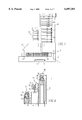
- FIG. 1 is exploded isometric view of a modular I/O unit in accordance with the invention.
- FIG. 1a is a partially exploded isometric view showing the interconnection of modules with a backplane within the modular I/O unit.
- FIG. 2 is a top view of the housing of the modular I/O unit of FIG. 1 with the electronics and personality modules removed.
- FIG. 3 is a side view of the I/O modular unit of FIG. 1 shown assembled.
- FIG. 4 is a sectional view through the terminals which form part of the modular I/O unit taken along the line 4--4 in FIG. 1.
- FIG. 5 is a schematic circuit diagram illustrating redundancy provided as one aspect of the invention.
- FIG. 6 is a schematic diagram illustrating implementation of a test function in accordance with another aspect of the invention.
- FIG. 7 is a front elevation view of a process control system incorporating a controller and a number of modular I/O units incorporating the invention.
- the modular input/output (I/O) system 1 of the invention includes as its basic components a base 3 in which a backplane 5 and a bank 7 of electrical terminals 9 are permanently mounted, and a pair of interchangeable electronics modules 11 and personality modules 13.
- Base 3 includes a bottom member 15 and top member 17 between which the backplane 5 is clamped.
- the backplane 5 has a pattern 19 of electrical conductors, to be described in more detail below, which selectively connect terminals 9 to the electronics modules 11 and personality module 13.
- the housing 3 supports dual arrangements of terminals 9, electronics modules 11 and personality modules 13.
- FIG. 3 It will be understood that other arrangements could include a housing or base mounting a single set of a bank of terminals, an electronics module and a personality module, or three or more sets of these components.
- the base 3 is secured to a mounting rail 12 such as a standard DIN rail by a clamp 14, as seen in FIG. 3. This clamp is actuated by a screw 16 accessible through the top member 17 of the base, as shown in FIG. 2.
- each of the terminals 9 of each bank of terminals 7, are conveniently arranged in three tiers which can be labeled A, B and C for a three-phase electrical system.
- each of the terminals includes a contact 21 which extends downward and terminates in a pointed end which engages holes ss (see FIGS. 1 and 1a) in the backplane 5 where it is connected to the circuitry 19.
- Terminal screws 23 engaged in clamps 25 secure the contacts 21 to field wiring 27.
- the electronics module 11 includes a housing 29 in which are mounted a pair of circuit cards 31 and 33.
- the circuit card 31 contains the I/O signal processing circuitry 35.
- signal processing circuitry 35 performs one or more functions which can include filtering, amplification or attenuation, surge protection, isolation, range limiting or scaling, and pulse shaping or other signal conditioning.
- the second card 33 in the electronics module housing 29 is the communications card through which signals are transmitted between the signal conditioning circuitry 35 and the processing system for which the I/O is provided.
- Mounted on the signal processing card 31 and the communications card 33 adjacent an opening 39 in the bottom in the housing 29 are electrical connectors 41 and 43, respectively.
- the personality module 13 is a switching module. It includes a housing 45 containing a circuit card 47 having switching circuitry 49, which as will be seen. can have a plurality of configurations. An electrical connector 51 is provided on the bottom edge of the circuit card 47 adjacent an opening 53 in the housing 45.
- the top member 17 of the base 3 has an opening 55 which forms side-by-side sockets 57 and 59 for plug in of the electronics module 11 and personality or switching module 13, respectively.
- Mounted on the backplane 5 in alignment with the socket 57 are electrical connectors 61 and 63 which mate with the connectors 41 and 43 in the electronics module.
- the connector 61 electrically connects the signal processing card 31 with the I/O circuits 19 on the backplane while the connector 63 connects the communications circuitry on the communications card 33 with communication busses indicated at 65 on the backplane.
- Connectors 67 on each end of the backplane connect the communication busses 65 with adjacent I/O units 1 or a controller in a manner to be discussed.
- the connectors 67 and communications bus 65 provide power to the electronics module 11 in addition to routing signals to and from the modules.
- the connector 51 on the circuit card 47 of the personality or switching module 13 mates with a connector 69 on the backplane 5 to connect to the switching circuitry 49 with the circuits 19 as the personality module 13 is plugged into the socket 59.
- octagonal keys on the backplane 5 assure that only an electronics module of a given type having a matching key (not shown) can be plugged into the socket 57.
- FIG. 5 is a schematic diagram illustrating application of the invention to provide redundancy for the electronics modules 11.
- the circuitry 35 1 of electronics module 11 1 has two channels A and B, each with an analog to digital (A/D) converter 71 1a and 71 1b connected through back plane circuitry 19 1 and switching module 13 1 to associated terminals 9 1a and 9 1b connected to the field wiring 27.
- the A/D converters 71 convert the analog field signals on the field wiring 27 into digital signals for input to signal conditioning circuits 73 1 in the module 11 1 .
- the conditioned digital signals are transmitted to a controller 75 over communications bus 65.
- the personality module 13 1 includes switch 79 1 .
- the switch 79 1 may be a relay as shown or solid state switching.
- the relay 79 has contacts 81 1a and 81 1b which in an unactuated position (not as shown in FIG. 5) connect the terminals 9 1a and 9 1b and the field wiring 27 to the associated electronics module 11 1 .
- the contacts 81 1a and 81 1b connect the field wiring to leads 83 1a and 83 1b in the module 13 1 .
- the leads 83 1a and 83 2b are connected through terminals 85 to transfer leads 87, which are connected through similar terminals 85 to leads 83 2a and 83 2b in an adjacent personality module 13 2 .
- the personality module 13 2 also includes a switch 79 2 which may be a solid state switch or, as shown, a relay. Contacts 81 2a and 81 2b of the relay 79 2 are shown in their unactuated position in which they connect field wiring 27 through the associated terminals 9 2a and 92 2b to A/D converters 71 2a and 71 2b in the electronics module 11 2 .
- the third personality module 13 3 which is connected to the third electronics module 11 3 does not contain any switching but connects the transfer leads 87 through leads 83 3a and 83 3b to the backplane wiring 19 connected to the A/D converters 71 3a and 71 3b of the electronics module 11 3 .
- a fourth electronics module 11 4 serves as a control module which generates control signals for actuating the switches 79 1 and 79 2 in the switching or personality modules 13 1 and 13 2 , respectively.
- the electronics module 11 4 has digital output circuits DO 89 1 and 89 2 generating contact output signals which are passed by the circuity 19 4 on the backplane to the associated terminals 9 4 .
- Control leads 91 1 and 91 2 are connected between these terminals 9 4 and the switches 79 1 and 79 2 .
- the personality module 13 4 does not provide any switching. With neither of the switches 79 1 or 79 2 actuated, the electronics modules 11 1 and 11 2 are connected through the associated field terminals 9 1 and 9 2 to their assigned field wiring 27.
- the redundant electronics module 11 3 is in a stand-by status. If the controller 75 detects a malfunction in one of the electronics modules 11 1 or 11 2 or if it is desired to take one of these electronics modules out of service such as for maintenance or testing, a signal is transmitted over the communications bus 65 to the control electronics module 11 4 to activate the appropriate digital output 89 1 or 89 2 . For example, if the electronics module 11 1 has failed in either channel, the DO 89 1 is actuated to generate a control signal which energizes the switch 79 1 .
- the transfer leads 87 can be connected to the leads 83 through them, and the additional terminals 85 are not required.
- the redundant electronics modules such as the module 11 3 can serve as a back-up for just one module 11 1 for two electronics modules 11 1 and 11 2 as shown, or for any number of electronics modules 11.
- FIG. 6 is a circuit diagram illustrating an application of the invention for implementing the test function.
- the electronics module 11 5 serves as a test module which generates test signals under control from the controller 75 through communications bus 65.
- the digital test signals are received by receiving circuit 92 and are converted to analog signals in the digital to analog (D/A) converters 93 1 and 93 2 for the two channels of the module 11 5 .
- the personality module 13 5 performs no switching functions so that the backplane circuits 19 5 deliver the test signals to the terminals 9 5 .
- Transfer leads 87 provide the test signals to terminals 85 on the personality modules 13 6 and 13 7 .
- the terminals 85 are connected to leads 83 6 and 83 7 in the switching modules 13 6 and 13 7 , respectively.
- Switches 79 6 and 79 7 which again may be solid state switches or relays as shown, switch either the test signals on the leads 83 6 and 86 7 or field signals from the field wiring 27 provided through the terminals 9 6 and 9 7 and the backplane circuits 19 6 and 19 7 .
- the contacts 81 6a and 81 6b apply the test signals to the A/D converters 71 6a and 71 6b of the electronics module 11 6 when the switch 79 6 is actuated.
- the test signals are processed by the signal processing circuits 73 6 and returned to the controller 75 for analysis over the communications bus 65.
- the contacts 81 7a and 81 7b apply the test signals to the appropriate channels of the electronics module 11 7 when the corresponding switch 79 7 is actuated.
- the electronics module 11 4 again serves as a control module which generates control signals through the DOs 89 1 and 89 2 when commanded by the controller 75.
- the transfer leads 87 can be connected to the switching modules 13 6 and 13 7 through these terminals and leads in the backplane 19 6 and 19 7 , instead of through the separate connectors 85.
- the control signals for the switches 79 can also be applied through these additional terminals and backplane wiring 19. In such a case, the switching module makes all the necessary connections through insertion in the socket in the base member.
- test equipment can be used to supply the test signals which are selectively switched by the switches 79, or the switches 79 can be used to disconnect the field signals while test signals are injected through test points (not shown).
- the modular I/O units 1 may be arranged in branches 95 1 and 95 2 which are connected to the controller such as the single/redundant controller 75'.
- the communications buses 65 and adjacent modular I/O units 1 are interconnected by the connectors 67 to connect each of modules to the controller 75'.
Abstract
Description
Claims (7)
Priority Applications (1)
| Application Number | Priority Date | Filing Date | Title |
|---|---|---|---|
| US08/846,400 US6097303A (en) | 1997-04-30 | 1997-04-30 | Modular input/output system with redundancy and testing |
Applications Claiming Priority (1)
| Application Number | Priority Date | Filing Date | Title |
|---|---|---|---|
| US08/846,400 US6097303A (en) | 1997-04-30 | 1997-04-30 | Modular input/output system with redundancy and testing |
Publications (1)
| Publication Number | Publication Date |
|---|---|
| US6097303A true US6097303A (en) | 2000-08-01 |
Family
ID=25297823
Family Applications (1)
| Application Number | Title | Priority Date | Filing Date |
|---|---|---|---|
| US08/846,400 Expired - Lifetime US6097303A (en) | 1997-04-30 | 1997-04-30 | Modular input/output system with redundancy and testing |
Country Status (1)
| Country | Link |
|---|---|
| US (1) | US6097303A (en) |
Cited By (16)
| Publication number | Priority date | Publication date | Assignee | Title |
|---|---|---|---|---|
| US6517358B2 (en) * | 2000-12-12 | 2003-02-11 | Hewlett-Packard Company | Method and system for directly interconnecting storage devices to controller cards within a highly available storage system |
| US6631076B2 (en) * | 1997-10-06 | 2003-10-07 | Phoenix Contact Gmbh & Co. | Switch cabinet |
| US6748474B1 (en) * | 2000-02-25 | 2004-06-08 | Telica, Inc. | Midplane apparatus |
| US20040252469A1 (en) * | 2003-06-10 | 2004-12-16 | Campbell Robert G. | Card guide for expansion circuit card |
| CN103336425A (en) * | 2013-07-04 | 2013-10-02 | 北京新航智科技有限公司 | Actively-abandoning type undisturbed switching method applied to industrial automation redundancy analog output equipment |
| US20140149630A1 (en) * | 2006-09-19 | 2014-05-29 | Fisher-Rosemount Systems, Inc. | Apparatus and methods to communicatively couple field devices to controllers in a process control system |
| CN104714406A (en) * | 2014-12-31 | 2015-06-17 | 重庆川仪自动化股份有限公司 | Redundancy switching method of input and output module |
| USD735667S1 (en) | 2013-09-27 | 2015-08-04 | Abb Technology Ag | Industrial control system module |
| EP3051370A1 (en) * | 2011-07-08 | 2016-08-03 | Rockwell Automation Technologies, Inc. | Industrial control using a high availability backplane |
| US9411769B2 (en) | 2006-09-19 | 2016-08-09 | Fisher-Rosemount Systems, Inc. | Apparatus and methods to communicatively couple field devices to controllers in a process control system |
| USD765031S1 (en) | 2015-01-30 | 2016-08-30 | Abb Technology Ag | Distributed control system module |
| CN106462131A (en) * | 2014-06-02 | 2017-02-22 | 凤凰通讯发展及制造股份有限公司 | Universal I/O signal interposer system |
| US9711886B2 (en) * | 2015-03-30 | 2017-07-18 | Honeywell International Inc. | SD card access door |
| CN109634895A (en) * | 2018-12-10 | 2019-04-16 | 浪潮(北京)电子信息产业有限公司 | A kind of IO card |
| EP3798769A1 (en) * | 2019-09-26 | 2021-03-31 | Rockwell Automation Technologies, Inc. | Distributed modular i/o device with configurable single-channel i/o submodules |
| DE102020101085A1 (en) | 2020-01-17 | 2021-07-22 | Phoenix Contact Gmbh & Co. Kg | Device for processing signals between a controller and field devices |
Citations (7)
| Publication number | Priority date | Publication date | Assignee | Title |
|---|---|---|---|---|
| US4574068A (en) * | 1982-12-14 | 1986-03-04 | General Electric Company | Universal logic card |
| US4774510A (en) * | 1986-05-09 | 1988-09-27 | Electrocon, Inc. | Monitoring annunciator apparatus |
| EP0489163A1 (en) * | 1990-06-22 | 1992-06-10 | Fanuc Ltd. | Printed board for branching signal lines from numeric controller |
| US5159534A (en) * | 1991-01-22 | 1992-10-27 | Johnson Service Company | Electronic/electromechanical packaging arrangement for facility management system |
| US5202822A (en) * | 1990-09-26 | 1993-04-13 | Honeywell Inc. | Universal scheme of input/output redundancy in a process control system |
| US5210756A (en) * | 1990-09-26 | 1993-05-11 | Honeywell Inc. | Fault detection in relay drive circuits |
| US5472347A (en) * | 1993-09-17 | 1995-12-05 | Allen-Bradley Company, Inc. | System for interconnecting I/O modules for data communications over a common backplane |
-
1997
- 1997-04-30 US US08/846,400 patent/US6097303A/en not_active Expired - Lifetime
Patent Citations (7)
| Publication number | Priority date | Publication date | Assignee | Title |
|---|---|---|---|---|
| US4574068A (en) * | 1982-12-14 | 1986-03-04 | General Electric Company | Universal logic card |
| US4774510A (en) * | 1986-05-09 | 1988-09-27 | Electrocon, Inc. | Monitoring annunciator apparatus |
| EP0489163A1 (en) * | 1990-06-22 | 1992-06-10 | Fanuc Ltd. | Printed board for branching signal lines from numeric controller |
| US5202822A (en) * | 1990-09-26 | 1993-04-13 | Honeywell Inc. | Universal scheme of input/output redundancy in a process control system |
| US5210756A (en) * | 1990-09-26 | 1993-05-11 | Honeywell Inc. | Fault detection in relay drive circuits |
| US5159534A (en) * | 1991-01-22 | 1992-10-27 | Johnson Service Company | Electronic/electromechanical packaging arrangement for facility management system |
| US5472347A (en) * | 1993-09-17 | 1995-12-05 | Allen-Bradley Company, Inc. | System for interconnecting I/O modules for data communications over a common backplane |
Cited By (23)
| Publication number | Priority date | Publication date | Assignee | Title |
|---|---|---|---|---|
| US6631076B2 (en) * | 1997-10-06 | 2003-10-07 | Phoenix Contact Gmbh & Co. | Switch cabinet |
| US6748474B1 (en) * | 2000-02-25 | 2004-06-08 | Telica, Inc. | Midplane apparatus |
| US6517358B2 (en) * | 2000-12-12 | 2003-02-11 | Hewlett-Packard Company | Method and system for directly interconnecting storage devices to controller cards within a highly available storage system |
| US20040252469A1 (en) * | 2003-06-10 | 2004-12-16 | Campbell Robert G. | Card guide for expansion circuit card |
| US7187555B2 (en) * | 2003-06-10 | 2007-03-06 | Hewlett-Packard Development Company, L.P. | Card guide for expansion circuit card |
| US9495313B2 (en) * | 2006-09-19 | 2016-11-15 | Fisher-Rosemount Systems, Inc. | Apparatus and methods to communicatively couple field devices to controllers in a process control system system |
| US20140149630A1 (en) * | 2006-09-19 | 2014-05-29 | Fisher-Rosemount Systems, Inc. | Apparatus and methods to communicatively couple field devices to controllers in a process control system |
| JP2014209380A (en) * | 2006-09-19 | 2014-11-06 | フィッシャー−ローズマウント システムズ,インコーポレイテッド | Apparatus and methods to communicatively couple field devices to controllers in process control system |
| US9411769B2 (en) | 2006-09-19 | 2016-08-09 | Fisher-Rosemount Systems, Inc. | Apparatus and methods to communicatively couple field devices to controllers in a process control system |
| EP3051370A1 (en) * | 2011-07-08 | 2016-08-03 | Rockwell Automation Technologies, Inc. | Industrial control using a high availability backplane |
| CN103336425B (en) * | 2013-07-04 | 2016-02-10 | 北京新航智科技有限公司 | A kind of formula of initiatively abandoning no-harass switch method being applied to industrial automation redundancy analog output equipment |
| CN103336425A (en) * | 2013-07-04 | 2013-10-02 | 北京新航智科技有限公司 | Actively-abandoning type undisturbed switching method applied to industrial automation redundancy analog output equipment |
| USD735667S1 (en) | 2013-09-27 | 2015-08-04 | Abb Technology Ag | Industrial control system module |
| CN106462131A (en) * | 2014-06-02 | 2017-02-22 | 凤凰通讯发展及制造股份有限公司 | Universal I/O signal interposer system |
| CN106462131B (en) * | 2014-06-02 | 2019-01-25 | 凤凰通讯发展及制造股份有限公司 | General purpose I/O signal inserter system |
| CN104714406A (en) * | 2014-12-31 | 2015-06-17 | 重庆川仪自动化股份有限公司 | Redundancy switching method of input and output module |
| CN104714406B (en) * | 2014-12-31 | 2017-06-09 | 重庆川仪自动化股份有限公司 | Input/output module redundancy switching method |
| USD765031S1 (en) | 2015-01-30 | 2016-08-30 | Abb Technology Ag | Distributed control system module |
| US9711886B2 (en) * | 2015-03-30 | 2017-07-18 | Honeywell International Inc. | SD card access door |
| CN109634895A (en) * | 2018-12-10 | 2019-04-16 | 浪潮(北京)电子信息产业有限公司 | A kind of IO card |
| EP3798769A1 (en) * | 2019-09-26 | 2021-03-31 | Rockwell Automation Technologies, Inc. | Distributed modular i/o device with configurable single-channel i/o submodules |
| US11243504B2 (en) | 2019-09-26 | 2022-02-08 | Rockwell Automation Technologies, Inc. | Distributed modular I/O device with configurable single-channel I/O submodules |
| DE102020101085A1 (en) | 2020-01-17 | 2021-07-22 | Phoenix Contact Gmbh & Co. Kg | Device for processing signals between a controller and field devices |
Similar Documents
| Publication | Publication Date | Title |
|---|---|---|
| US5984734A (en) | Modular input/output system with flexible interface with field wiring | |
| US6097303A (en) | Modular input/output system with redundancy and testing | |
| US6275881B1 (en) | Device for inherently safe signal matching | |
| JP3786455B2 (en) | Modular terminal block device for control equipment | |
| US5222166A (en) | Aircraft fiber optic data distribution system | |
| US4179172A (en) | Modular hardware packaging apparatus | |
| US5495584A (en) | SCSI bus concatenator/splitter | |
| EP1643608A2 (en) | Individually and redundantly addressable solid-state power controllers on multiple modules in a power distribution assembly | |
| JPH056411B2 (en) | ||
| JP2505437B2 (en) | Power supply circuit | |
| US3953797A (en) | Electronic equipment assembly comprising plug-in modules and test bars | |
| US4384755A (en) | Electrical harness interface system | |
| US5282112A (en) | Backplane having a jumper plug to connect socket connections to a bus line | |
| JPH02170377A (en) | Integrated input/output interface device and connector module | |
| US6033268A (en) | Modular I/O system with two-way connectors between units and a common lock for multiple plug-in modules | |
| KR100676579B1 (en) | Control apparatus for controlling a machine | |
| US7032135B2 (en) | Equipment protection using a partial star architecture | |
| US4871324A (en) | Backplane for supporting removable modular | |
| US4970505A (en) | Three stage switching apparatus | |
| US5638255A (en) | Power protection and distribution module | |
| GB2329074A (en) | Electrical distribution system for a vehicle | |
| EP1012913A1 (en) | A set of devices for transferring electric signals | |
| US5395257A (en) | Fault-tolerant connector | |
| US4875869A (en) | Backplane with associated handling means | |
| CN213303666U (en) | Modular control equipment for safety level of nuclear power station |
Legal Events
| Date | Code | Title | Description |
|---|---|---|---|
| AS | Assignment |
Owner name: WESTINGHOUSE ELECTRIC CORPORATION, PENNSYLVANIA Free format text: ASSIGNMENT OF ASSIGNORS INTEREST;ASSIGNORS:LUNZ, KENNETH GEORGE;SIMON, DANIEL LOUIS;REEL/FRAME:008552/0775;SIGNING DATES FROM 19970328 TO 19970416 |
|
| AS | Assignment |
Owner name: WESTINGHOUSE PROCESS CONTROL, INC., A DELAWARE COR Free format text: ASSIGNMENT OF ASSIGNORS INTEREST;ASSIGNOR:CBS CORPORATION, FORMERLY KNOWN AS WESTINGHOUSE ELECTRIC CORPORATION;REEL/FRAME:009827/0525 Effective date: 19981116 |
|
| STCF | Information on status: patent grant |
Free format text: PATENTED CASE |
|
| AS | Assignment |
Owner name: EMERSON PROCESS MANAGEMENT POWER & WATER SOLUTIONS Free format text: CHANGE OF NAME;ASSIGNOR:WESTINGHOUSE PROCESS CONTROL, INC.;REEL/FRAME:014108/0946 Effective date: 20020729 |
|
| FPAY | Fee payment |
Year of fee payment: 4 |
|
| FPAY | Fee payment |
Year of fee payment: 8 |
|
| FPAY | Fee payment |
Year of fee payment: 12 |